MENG 411 Capstone Team Project Eastern Mediterranean...
57
MENG 411 Capstone Team Project Eastern Mediterranean University Faculty of Engineering Department of Mechanical Engineering Design and construction of Heat Exchanger for a Solar Parabolic Dish Collector Course Coordinator Assist. Prof. Dr. Mostafa Ranjbar Supervisor Prof. Dr. Uğur Atikol Team Members Joel Ikechukwu David 118305 Mayowa Familade 118648 Abdullah Awad 138942 Group Name: Parabolas CAPSTONE TEAM PROJECT FALL 2015-2016 1
Transcript of MENG 411 Capstone Team Project Eastern Mediterranean...

MENG 411 Capstone Team Project
Eastern Mediterranean University
Faculty of Engineering
Department of Mechanical Engineering
Design and construction of Heat Exchanger for a Solar Parabolic DishCollector
Course Coordinator
Assist. Prof. Dr. Mostafa Ranjbar
SupervisorProf. Dr. Uğur Atikol
Team Members Joel Ikechukwu David 118305
Mayowa Familade 118648
Abdullah Awad 138942
Group Name: Parabolas
CAPSTONE TEAM PROJECT FALL 2015-2016
1

JURY MEMBERS
Prof. Dr. Uğur Atikol (Supervisor)
Assoc. Prof. Dr. Qasim Zeeshan
Assist. Prof. Dr. Murat Özdenefe
2

ABSTRACTThe present project is concerned with the design and construction for a heat exchanger to
be used in the focal point of a solar parabolic dish collector. The main aim of the project is to use
solar radiation that will shine on the solar parabolic dish to heat the working fluid (such as water)
to generate hot water or steam. Among the many application this system can be used are heating
processes, generating electricity and absorption chillers. The project utilized a solar parabolic
dish which was covered with Aluminum foil which is a good reflective material and the heat
exchanger is made up of copper because copper is a good conductor of heat. After the design and
manufacturing of the system, the experiment was carried out during fall season on two separate
days which had a solar intensity reaching a maximum of 1152.59 W /m ² . Both the inlet and
outlet of the heat exchanger was measured with a K-type thermocouple. The experiment was
performed at a constant flow rate of 0.4L/min for the flowing water and it was checked at
intervals of 5minutes and the temperature increases from 17 ℃ to about 69 ℃ in 30
minutes.
3

TABLE OF CONTENTS
ABSTRACT iii
LIST OF FIGURES vii
LIST OF TABLES viii
NOMENCLATURES ix
CHAPTER 1 Introduction
1.1 Background 1
1.2 Problem definition 2
1.3 Objective of project 2
1.4 Limitations and span 3
1.5 Report organization 3
CHAPTER 2 Literature Review
2.1 Information 4
2.2 Previous researches 4
2.3 Solar engine one power plant 1913 5
2. Augustine Bernard Truncated Cone Solar Energy (1825-1912 5
CHAPTER 3 Design and Manufacturing
4

3.1 Overview of system 8
3.2 Alternative design 9
3.3 Initial design consideration 10
3.4 New design development 11
3.5 System breakdown structure 13
3.6 Functional block diagram 13
3.7 Solar Analysis of Famagusta 14
3.8 Theoretical background 14
3.9a Proposed design 16
3.9b Material selection 18
CHAPTER 4 Manufacturing, Assembly and Testing
4.1 Manufacturing procedures 20
4.2 Method of assembly 21
4.3 Testing 23
4.1 Cost analysis 24
CHAPTER 5 Results and Discussion
5.1 Results 26
5.2 Technical difficulties encountered31
5.3 Design improvement 32
5

CHAPTER 6 Conclusion and Future Work 33
REFERENCES 34
APPENDICES
Appendix A 37
Appendix B 43
Appendix C 44
Appendix D 50
6

LIST OF FIGURES
Figure 2.1 Mouchot design 6
Figure 2.2 Solar Parabolic dish 7
Figure 3.1 Parabolic trough collector 9
Figure 3.2 Initial heat exchanger design 10
Figure 3.3 Heat exchanger 11
Figure 3.4 Heat exchanger of a parabolic collector 12
Figure 4.1 20mm copper winding 20
Figure 4.2 Soldering process for the heat exchanger 22
Figure 4.3 Performance of experiment 23
Figure 4.4 Thermocouple testing 24
Figure 5.1 useful thermal energy vs time of day 27
Figure 5.2 Thermal efficiency vs time of day 28
Figure 5.3 Temperature outlet vs time of day 28
Figure 5.4 useful thermal energy vs time of day 30
Figure 5.5 Thermal efficiency vs time of day 31
Figure 5.6 Temperature outlet vs time of day 31
7

LIST OF TABLES
Table 2.1 Countries company project 7
Table 3.1 Properties of aluminum and copper 19
Table 4.1 Cost analysis 25
Table 5.1 Results on 9th January 201627
Table 5.2 Results on 10th January 2016 29
8

NOMENCLATURE
Aa :aperture area ( m2)
|¿|A ¿
: absorber area m2
¿ )
C :concentration ratio
Cpw :specific heat capacity of water at constant pressure (J/kg.k)
Da :aper turediameter (m)
FR :heat removal factor
F : focal length (m)
I b:beam radiation (W/ m2)
ID : longterm averagedirect radiation (W/ m2)
h :height of the dish (m)
mw :rate of heating water (kg/s)
|¿|:rate of energyabsorbed by the absorberP¿
(W)
Q :useful thermal energydeliverd (W)
T1 : temperature of heat transfer fluid entering thecollector ( ℃ )
T2 : temperature of heat transfer fluid leaving the collector ( ℃ )
T a:ambient temperature ( ℃ )
9

T w : temperature of water ( ℃ )
t : time is second (s)
t x : thickness of absorber wall (m)
U L :overallheat loss coefficient (W/m2K)
V w : volumeof water (L)
Ƞ : instaneous thermal efficiency ( ) / Ƞo: opticalefficiency ( ) /
Ψ rim :rimangle
10

CHAPTER 1
INTRODUCTION
1.1 Background
Solar energy is for sure the most ancient source of energy since the beginning of time. It
is the radiant light and heat energy emitted by the sun and harnessed using a wide range of new
evolving technologies. It is of a truth an important source of renewable energy and its related
technologies are widely characterized as either passive solar or active solar depending on the
way the energy is being captured, distributed or converted into solar power. For the past
centuries, solar energy has been increasingly used to either to produce electricity or to satisfy
various human wants. The distance between the earth and the sun is about 1.496∗108 km yet
the earth receives 175000 terawatts (TW) of incoming solar radiation at the upper part of the
atmosphere despite the distance apart from the sun [2]. Roughly 30% of this radiation is reflected
back to space while the remaining is absorbed by land masses, clouds and oceans [2]. The energy
absorbed by land masses and oceans keeps the surface at a mean temperature of 17ºC. Through
photosynthesis, green plants metamorphose solar energy into chemical energy which produces
food, biomas from which fossils fuels are derived and woods. Without the energy from the sun
all life on earth will end. A simple example of the power of the sun can be seen by using a
magnifying glass to focus the sun rays on a small amount of water. Before long the water begins
to heat. This is one way of using the suns energy but it is not efficient enough to boil water
unless by applications of many numbers of magnifying glasses. A more practical and reliable
way is by using a solar parabolic dish collector.
Solar parabolic dish collectors are the most powerful type of collectors because they are
one of the concentrated solar thermal collectors used for energy conversion and power generation
by concentrating sunlight radiation at a single point known as the Focal point. Parabolic dish
systems comprises of a parabolic shaped point focus concentrator that is in the form of a dish
that reflects sun rays onto a receiver (heat exchanger or generator) stationed on the focal point
where all energy is concentrated. In order to avoid confusion of the phraseology, the term
collector will be applied to the total system, including the receiver and the concentrator. The
1

receiver is an element of the system where the heat radiation is absorbed and then converted to
another form of energy; it includes the absorber, its associated covers and insulators. The
concentrator, or optical system, is that part of the collector that directs radiation onto the receiver.
The opening of the concentrator is the gap through which the solar radiation enters the
concentrator.
1.2 Problem definition
As stated above, the aim of this project is to design a heat exchanger which will function
as a medium to heat water into steam. However, there seems to be a problem in the design of this
project. The related problem is to design and construct a small and light weight heat exchanger at
the focus of the parabolic dish collector. This is because the total area of all the concentrated
energy from the sun to the focus is not so large and as a result the concentrated energies at the
focus will not completely encompass the heat exchanger.
1.3 Objective of project
The ultimate purpose of this research is to design and construct a small and concise heat
exchanger for a solar parabolic dish concentrator that heats fluid (such as water) to a high
temperature at a high flow rate
2

1.4 Limitations and span
In as much as solar energy is beneficial to this project there are also related limitations,
notwithstanding the fact that they are not so plentiful. The initial cost of purchasing and
installing solar parabolic dish collectors always become the first disadvantage. Despite the fact
that allocation programs, tax initiatives and rebate incentives are given by the government to
promote the use of parabolic collectors we are still way behind in making full and efficient use of
solar energy. As new technologies show up, the cost of parabolic collectors is likely to decrease.
Implementing this project on a full scale in rural areas will require more than just one parabolic
dish collector. As a matter of fact, multiple parabolic dish collectors will bring about more
electricity but at the same time it will require large land mass region to mount the dishes
(installation area) which can be a bit costly. Location of parabolic collectors is of a major
importance in generating electricity, areas which remains mostly cloudy and foggy will produce
electricity but at a reduced rate and this may also be a reason to install more parabolic collectors
to generate enough electricity.
Availability of the sun is usually not constant for 24hours here on earth therefore solar energy
proves to be useless during the night and another limitation is the fact of tracking the sun during
the day in order to get optimum heat radiation.
This project will deliberate about the topic of solar parabolic dish collector by first giving
information of other research work done on the subject-literature review, afterwards explaining
the methodology, design manufacturing, calculation and then ends with a conclusion and
discussion.
1.5 Report organization
The Chapter 2 of this report will discuss the literature review of the previous studies done
by the past scientist. The Chapter 3 will contain the design analysis of the system such as
equations. The Chapter 4 and 5 will elaborate on the manufacturing, assembly, testing, results
and discussion, and also the design improvement. Chapter 6 focuses on the conclusion and future
work as regards to the project while the references and appendices comes after
3
CHAPTER 2
LITERATURE REVIEW
2.1 Information
The use of solar energy is not widely spread until the 18th century where it is been used
for many applications like solar water heater, burning mirrors to light torches, renewable energy,
generating electricity. A solar parabolic dish collector is used to gather together rays from the
sunlight. The shape of the device is parabola because the sun rays falling on the dish are parallel
to one another and the parabolic dish will reflect the rays back at a focal point. This will only
happen if and only if there is a reflector on the dish, like glass or aluminum plate. Meanwhile,
losses reflected sun rays in any solar parabolic dish collector are due to imperfections of the dish
shape. The glass and aluminum are both materials that have the ability to reflect sun rays just
because of the way they gloom. At the focal point where the light rays are been concentrated is
been used for some things like putting a heat exchanger for boiling water, cooking pot for
cooking food or a turbine for generating electricity.
2.2 Previous researches
The second research titled Heat Exchanger Market by Type (Shell & Tube, Plate &
Frame, Air Cooled, Printed Circuit), by Application (Chemical, Petrochemical, Oil & Gas,
HVACR, Food & Beverage, Pulp & Paper, Power Generation), Classifications (MoC,
Temperature Range & Fluid Type) and Geography, Trends & Forecast to 2019 says European
region is the biggest market of heat exchangers, accounting for more than one-third of the total
heat exchangers demand [3]. Currently, Europe acquires more than 30.0% of the total global
market. Heat exchanger consumption in the region is estimated to grow at a CAGR of around
4.81% from 2014 to 2019. There is a lot of scope in the Asia-Pacific heat exchanger market due
to the surging demand for energy in the region. With the emerging technological developments
and innovations in the region, the demand for heat exchangers may further augment at a higher
pace. It is estimated to grow at a CAGR of 10.70% for the next five years [3].
4

2.3 Solar energy one power plant 1913
The Concentrated Solar Power (CSP) plant is the first documented Solar Engine [4]. In the
year 1912 the building of the solar parabolic trough collector started for the irrigation pumping
station. The location of the place for the construction of the concentrated solar power plant lies
on the River Nile south of Cairo, a water mineral resort town. The Solar engine had a capacity of
100 brake HP. The solar engine one was developed by a USA inventor called Frank Shuman [5].
Five parabolic concentrating reflectors were builds then, each of these collectors was 62m long,
4m wide, with 7.6m spacing facing the sun from east to west. This project or construction was
supported by a man called Lord Kitchener who offered 12000 hectares of land for cotton
plantation in Sudan.
2.4 Augustin Bernard Muochot (1825- 1912) truncated one solar engine
Augustin Bernard is best known as a mathematics lecturer in France, Lychee de Tour
to be precise [6]. He was the one that built a solar engine using a truncated cone dish. As a
mathematician, he thinks about the future that coal which was an industrial fuel at that time
would run out as time goes on. Is fear that time was that if there is no more coal, what would
happen to all the industries. In the year 1860 he performed an experiment which was his first
experiment with a solar cooking device. Initially he used Iron cauldron surrounded with a glass
of which solar radiation goes through it and boil the water. However, the pressure and amount of
steam were not that good. He realized that the addition of reflector could produce more steam to
operate the steam engine. Later on he constructed a solar engine in the form of a truncated cone
and he refined the reflector for a better the improvement in capacity. The steam engine powered a
water pump and on a sunny day produced a power of half HP (1/2 HP).
5

Figure 2.1 Mouchot design [6]
In figure 2.1 above shows the design of the great mathematician whose project was supported the
French Government.
The Government (French) also share in the view that coal might finish anytime soon. They
decided to sponsor Augustin’s project by constructing a larger boiler seventy liters of water and
thirty liters of steam boiler for a whole city called Constantine in Algeria. The project was
improved with the use of multi-tube boiler which makes it for larger heat transfer water which
yields a high amount of steam pressure and good performance.
Other countries and companies also built the solar parabolic dish collector for the help of the
people and the nation at large. In table 2.1 below it shows the some other review on the past
projects as far as solar parabolic dish collector is concerned. There are many others that are really
efficient however few have been mentioned below.
6

Table 2.1 Countries company project
PROJECT LOCATION(MWe)
CAPACITY(MWe)
TOTAL CAPACITY COMPANY AGENCIES
Parabolic dish Egypt 127 29 GEF grant
Parabolic dish Greece 50 50 OADYK EU
Parabolic dish Israel 100 100 Israel ministry of National Infrastructure
Parabolic dish Italy 40 40 ENEA
Parabolic dish India 140 35 GEF grant
Parabolic dish Algeria 140 35 New Energy
In conclusion, there has been improvement in the solar parabolic dish collector compared
to the old ways of doing it, improvement in the type of material to be used for the reflector and
the dish itself, and improvement in the efficiency of the dish which gives better performance.
Figure 2.2 Solar parabolic dish [7]
In figure 2.2 above shows examples of solar parabolic dish collector used for cooking and
heating metals respectively. This same invention could be used to generate electricity.
7

CHAPTER 3
DESIGN AND ANALYSIS
3.1 Overview of system
In order to victoriously design and develop a functional solar parabolic dish collector,
certain major components must be made available. The major components of this system are the
solar parabolic concentrator which is mainly used for the collection of sunlight from a large
region by focusing it on a single point and the heat exchanger which is placed at the focus.
The reflective material used in reflecting the sun rays off the parabolic dish is the
aluminum reflector. Aluminum appears to be a non-ferrous metal, it is quite easy to shape and
suitably perfect for all types of machining. After bending, stamping, treatment of surface, process
of machining and shaping, its performance can be better to meet the production of different
aluminum products. Aluminum is recognized for its low density and ability to withstand
corrosion. Aluminum reflector is one of the most reflective metals in the world due to the fact
that it has a mirror like surface and is made from very high purity aluminum with photometric
qualities to control light.
Heat exchangers are devices that enhances the transfer of heat between two fluids (gas or
liquid) that are at separate temperatures while keeping them from contacting each other. Heat
exchangers are usually used in practice in a vast range of applications, from air-conditioning
systems and heating in a household, to power production in large plants and chemical processing.
Majority of heat exchangers can either exists as parallel flow heat exchangers or counter-flow
heat exchangers. In the case of the parallel flow heat exchangers, the two fluids move in the
same direction while for the counter-flow heat exchangers the two fluids move opposite in
direction.
8

3.2 Alternative design
An alternative design can be a solar parabolic trough collector. This is a type of solar
thermal collector that is straight in one dimension and curved as a parabola in the other two,
lined with a polished metal mirror. The energy of sunlight which enters the mirror parallel to its
plane of symmetry is focused along the focal line, where objects are positioned that are intended
to be heated. Parabolic trough concentrators have a simple geometry, but their concentration is
about 1/3 of the theoretical maximum for the same acceptance angle, that is, for the same overall
tolerances of the system to all kinds of errors [7]. The theoretical maximum is better achieved
with more elaborate concentrators based on primary-secondary designs using non imaging
optics which may nearly double the concentration of conventional parabolic troughs and are used
to improve practical designs such as those with fixed receivers. An elaborate depiction of a
parabolic trough is shown in the figure 3.1 below.
Figure 3.1 Parabolic trough collector [7]
9

3.3 Initial design consideration
Having chosen a parabolic collector over a trough collector was due to the fact that a
parabolic collector is more powerful and it focuses all the energies from the sun at a single point.
The initial design proposal of the heat exchanger that is designed for this system was neither a
parallel nor counter flow heat exchanger. The design of the heat exchanger was based on having
series of in-line copper tubes were both ends of the tubes will be connected to two semi-circular
copper tubes. Water goes in through one of the semi-circle tube and flows through the straight
tubing’s then leaving out from the other semi-circle tube. This heat exchanger will be placed at
the focus of the parabolic dish collector were all the heat energy is reflected to. Figure 3.2 below
depicts the geometry and design.
Figure 3.2 Initial heat exchanger design
10

3.4 New design development
The new design of the heat exchanger is based on having series of wound up spiral
copper tubes as this is to increase the surface area compared to the previous design as well as
increasing the time for the water to exit the system thereby giving room for a higher temperature
of water at exit. Both ends of the spiral tubes will be connected to two semi-circle copper tubes.
Water goes in through one the semi-circle tube and flows through the spiral tubing’s then leaving
out from the other semi-circle tube. This heat exchanger will be placed at the focus of the
parabolic dish collector were all the heat energy is reflected to. The copper heat exchanger
becomes hot quickly due to its high rate of conductivity which results to heating up cold water
that flows in from the inlet of the system before exit.
Figure 3.3 Heat exchanger
The above figure 3.3 illustrates a cylindrical heat exchanger and a water tubing that will be
passed through it.
11

Figure 3.4 Heat exchanger of a parabolic collector
The above figure 3.4 illustrates how the system will be designed. As you can see, the heat
exchanger is placed at the focus of the parabolic dish collector where all the incident rays from
the sun is directed to.
12

3.5 System breakdown structures
3.6 Functional block diagram
13
HEAT EXCHANGER FOR A SOLARPARABOLIC DISH COLLECTOR
Aluminum sheetreflector and
aluminum dish
Parabolic dishreflector
Heat exchanger
Copper Spiralpipes and elbows
HEATABSORPTION
PARABOLICREFLECTOR
RADIATION
HOT WATER HEATEXCHANGER
SUN

3.6 Solar analysis of localization (Famagusta)
To adequately design our system to create the required output some basic factors have to
be put in place. These factors include, the intensity of radiation of sunlight in our locality
Famagusta, Turkish Republic of Northern Cyprus, materials to be used and their properties, these
will all be discussed shortly.
First of all, Famagusta is situated at the longitude and latitude coordinates of 33.95 and 35.125
[8]. Famagusta has a typical Mediterranean climate- warm dry summers and mild winters. The
typical Mediterranean climate has a temperature in excess of 22.0 °C average monthly to be the
warmest period and an average in the coldest month between 18 to -3 °C. Since the sun’s
radiation on earth is a function of the geometry of the receiving surface relative to the sun, it is
important therefore to notice several geometric angles that show the sun-earth surface relations.
The declination of the sun for any given day can be calculated approximately with the equation:
δ = 23.45 sin [(360/365)* (284+n)]; Where n is the day of the year. In engineering
calculations, this declination is considered to be constant for any given day [9].
3.7 Theoretical background
Several parameters are used to describe solar concentrating collectors. Given below are
brief descriptions of some of these parameters: The aperture area Aa is the area of the collector
that intercepts solar radiation. The Acceptance angle is defined as the angle through which a
source of light can be moved and still converge at the receiver [10]. A concentrator with small
acceptance angle is required to track the sun continuously while a concentrator with large
acceptance angle needs only seasonal adjustment. The absorber area Aabs is the total area of the
absorber surface that receives the concentrated solar radiation. It is also the area from where
useful energy can be gained. The Concentration ratio C is defined as the ratio of the aperture
area to the absorber area i.e.
A|¿|
C=Aa
¿ [13] 1
14

Where Aa=¿ Aperture area, |¿|A¿ = Absorber area
The optical efficiency is defined as the ratio of the energy absorbed by the absorber to the energy
incident on the concentrator aperture (Garg and Prakash, 2000). It includes the effect of
mirror/lens surface, shape and reflection/transmission losses, tracking accuracy, shading,
receiver-cover transmittance, absorptance of the absorber and solar beam incidence effects. The
optical efficiency is given as:
P|¿|
Aa . IDoȠ =¿
[13] 2
Where |¿|P¿ = rate of energy absorbed by the absorber (W), ID=¿ direct radiation(W/ m2
)
The optical efficiency of most solar concentrators lies between 0.6 and 0.7. In a thermal
conversion system a working fluid is used to extract energy from the absorber. The thermal
performance of solar concentrator is determined by their thermal efficiency.
The thermal efficiency is defined as the ratio of the useful energy delivered to the energy incident
at the concentrator aperture:
T ₂−T ₁¿
ρV CPF ¿
Ƞ=¿ [13] 3
The incident solar radiation consists of beam (direct) and diffuse radiation. However, the
majority of concentrating collectors can utilize only beam radiation. The instantaneous thermal
efficiency of a solar concentrator may be calculated from an energy balance on the absorber. The
useful thermal energy delivered by a concentrator is given by:
|¿|−T a
T¿
¿|¿|
Q= oȠ . I b . Aa.−U L¿
[13] 4
15

Therefore, the instantaneous thermal efficiency may be written as:
|¿|−T a
T ¿
¿UL¿
Ƞ=qu
I b . Aa
= oȠ −¿
[13] 5
At higher operating temperatures the radiation loss term dominates the convection losses and the
energy balance equation may be written as:
Q = o. Ƞ I b . Aa−U L (T|¿|
4
¿ - T a4
)|¿|A ¿ [13] 6
Instead of Eq. (4). In Eq. (6) U L takes into account the accompanying convection and
conduction losses also. The instantaneous thermal efficiency η is now given by:
T|¿|4−Ta
4
¿¿
UL¿
Ƞ= oȠ −¿
[13] 7
Since the absorber surface temperature is difficult to determine, it is convenient to express the
efficiency in terms of the inlet fluid temperature by means of heat removal factor FR as:
−¿T a
T L¿
¿Ƞo−U L¿
¿Ƞ=FR¿
[13] 8
The instantaneous thermal efficiency is dependent on two types of quantities, namely the
concentrator design parameters and the parameters characterizing the operating conditions. The
optical efficiency, heat loss coefficient and heat removal factor are the design dependent
parameters while the solar flux, inlet fluid temperature and the ambient temperature define the
operating conditions.
16

3.8 Proposed design
Now we will count for area of the aperture: Aa=π (Da )
2
4
We will take the diameter of the aperture: Da=1.22m ; Aa=π (Da )
2
4=1.2m 2
Also we take the absorber to be a half cylinder with {r=0.085m} ; height (0.16m)
The effective surface area of the absorber is given by: |¿|=π rh
A¿
|¿|A ¿
= π (0.085 )(0.16) =0.04272 m ²
The half-acceptance angle is given by:
C=1
sin ²ø≫ø=sin−1√ 1
C ; Where C is concentration ratio?
Recall that C=AaAabs
=28
ø=sin−1√ 128
=10.8933⁰
The optimum rim angle is: Ψ rim=90−ø
The focal length, f, of the dish is obtained from [12]: F= Da2
/16h ; h=height of dish
F=1.222/16(0.2) =0.46m
Expected or assumed thermodynamic performance of the system
The estimated useful energy of the designed heat exchanger of parabolic collector is given by:
Q =Ƞ I b Aa ; Where I b=¿ beam radiation, Ƞ =thermal efficiency
The efficiency range of most solar concentrators is 40% - 60% [13].
17

I b=ID=750W /m ² (Average of 400-2500 in Cyprus)
Ƞ=0.5 (Average of 0.4 and 0.6)
Q=0.6×750×1.2=540W
The useful energy is also given by:
Q=mwCpw (T w−T a )=Ƞ . ID . Aa 9
Where mw is the rate of heating the water and Cpw is the specific heat capacity at constant
pressure of the water is obtained from tables of properties of water 4185J/kgK (at 15⁰C) [14]. We
have (m= 0.4kg), also the estimated time for water to exit the heat exchanger is t =60s. The time
was estimated by filling a bottle of water which is 0.4L, the same volume with the volume of the
heat exchanger. When the time was turned on, it took 60s to fill the bottle up. The volume of the
water can be easily calculated by dividing the mass which is measured above and divide it by the
density of the water at given temperature.
The density of the water at 15 Celsius is 999.1 kg/ m3.
So, V=mρw
=0.4kg999.1
=4×10⁻⁴m3
= 0.4 L
V =0.4L/min
mw=mt=
0.4 kg60 s
=0.006 kg/s
We have the equation to find the exit temperature as follow:
Q=mwCpw (T exit−T inlet ) 540=0.006kgs.4185
jkgk
. (T exit−15 ) T exit=36.5 ⁰C
18
The energy, Pabs, absorbed by the absorber is obtained from Eq. (2):
Ƞ0=0.65 (Is the average of 0.6 and 0.7) and the bracketed term is same as qu
|¿|=0.65×1.2×750=585WP¿
3.9 Material selection
Material used for the body of dish:
Aluminum was chosen over steel due its low cost, energy effectiveness, lightness, and
easy fabrication of material for the body of the dish. Due to its lightweight the overall weight of
the system is reduced, and it also tends to reduce the degree of work to be done by the super-jack
from west to east and vice versa.
Material used for the heat exchanger:
Copper was chosen due to its high level of thermal conductivity, energy effectiveness.
This mean that by heating one end of a piece of copper, the other end will quickly reach the same
temperature. Most metals are pretty good conductors; however, apart from silver, copper happens
to be the best. It is used in many heating applications because it doesn’t corrode and has a high
melting point, therefore it is used in the application of a heat exchanger. Copper can be joined
easily by soldering or brazing. This is important for pipework’s and for making sealed copper
vessels. The overall weight of the heat exchanger is reduced due to the light weight of copper
and also the work done in turning the dish about its horizontal axis by the super-jack is reduced.
Surface coating material for the heat exchanger:
Black paint was picked out for the coating of the heat exchanger. It is chosen over other
coating materials due to the fact that it has a higher level of absorptivity at angles other than
normal incidence, constancy and durability when exposed to weathering, cost effectiveness and
protection to the heat exchanger, sunlight and high stagnation temperature.
Material used for the base of the parabolic dish collector:
19

Angular and flat steel bars were selected for the base which support the whole solar
parabolic dish system. Flat and angular bars were chosen to create solid and rigid supports for
the rectangular, vertical axis steel bar which supports the parabolic dish.
TABLE 3.1 Properties of aluminum and copper
Property Copper(Cu-ETP) Aluminum(1350) Units
Electrical-conductivity 101 61 %IACS
Electrical resistivity(annealed) 1.72 2.83 mOhm-cm
Thermal conductivity at 20°C 397 230 W/mK
Coefficient of expansion 17 x 10-6 23 x 10-6 /°C
Tensile strength (annealed) 200-250 50-60 N/mm2
Tensile strength (half-hard) 260-300 85-100 N/mm2
0.2% proof strength (annealed) 50-55 20-30 N/mm2
0.2% proof strength (half-hard) 170-200 60-65 N/mm2
Elastic modulus 116-130 70 N/mm2
Fatigue Strength (annealed) 62 35 N/mm2
Fatigue Strength (half hard) 117 50 N/mm2
Specific heat 385 900 J/kgK
Density 8.91 2.70 g/cm3
Melting Point 1083 660 °CThe table 3.1 illustrates the different physical or characteristics of both aluminum and
copper.
CHAPTER 4
MANUFACTURING, ASSEMBLY and TESTING
4.1 Manufacturing Procedure
20

Different manufacturing processes were used in the production of our project. The
processes includes winding, drilling, soldering, use of sandpaper, welding. Firstly, a hollow 13cm
steel cylinder is being held stationary upward by the use of a bench vise to avoid movement. The
straight 20mm copper tube is filled with dry beach sand and then closed at both ends as this is to
prevent it from compressing during winding process. This tube is clamped to the hollow cylinder
by the use of a G-clamp and then wounded round the cylinder severally to form spirals. As it is
known that spirals are circular, a single circle was picked and then cut into to two semi-circles.
After the accomplishment of this process, the sand was evacuated from the semi-circle tubes and
a total of eight holes were drilled round the tube.
Figure 4.1 20mm copper winding
The above Figure 4.1 depicts the winding process of the 20mm copper tube done around the
hollow cylinder with the use of a bench vice and G-clamp and also the drilling process.
Next step is winding the 8mm copper tube to also form series of spirals. A cylindrical
steel rod of 22mm is placed immobile upward on a bench vice. The 8mm tube is filled with sand
also in order to prevent compression during winding. The tube is clamped to the steel rod by the
use of a smaller G-clamp and then wounded round the steel rod multiple times to form a spiral,
21

after which the sand is removed by using compressed air and a total of five different spirals were
made. Two tubes were wounded to form a single spiral having made three sets, and a single tube
is wounded also to form a single spiral having made two sets making a total of five different
spirals. This then amounts to having a total of eight passes of spirally wounded 8mm copper tube
connected to the two 20mm semi-circle tube.
4.2 Method of assembly
The methods of assembly used for the project were done manually and also performed in
the workshop of mechanical engineering department excluding the soldering which was done in
another workshop located outside the department. The major processes involved here is screwing
and soldering. For the assembly of the heat exchanger, both ends of the sets of copper spiral
tubes were attached to the semi-circle tubes by mode of soldering as welding cannot be used for
this kind of joining. Copper elbows were connected to the semi-circle copper tubes for the inlet
an outlet of the fluid flow. The figure 4.2 shows how the soldering is carried out to for the
connections of the spiral tubes and the elbows.
Figure 4.2 Soldering process for the heat exchanger
22

Next, surface cleaning of the parabolic dish is done with the use of sand paper to eliminate
uneven surfaces before an adhesive aluminum reflector is placed on the parabolic dish. This
process requires careful assembly in order to avoid air bubbles while installation is carried out.
Furthermore, in order to keep the heat exchanger at the focus of the parabolic reflector, long
screws were attached with nuts from the base of the dish up to the focus so as to hold the heat
exchanger there.
4.3 Testing
The testing was done during mid-day and the weather conditions was quite favorable
despite the fact that the experiments was done in fall season when there is little sunshine.
Recording and data was collected for just one day as it was forecasted in the news that there is
little sunshine. These data and results will be discussed in the following chapter. For the testing
to be carried out, the heat exchanger was placed at the focus of the parabolic reflector as
aforementioned before. The system was taken outside of the mechanical engineering department
and was faced to the sun so as to get the incident rays of the sun. For the measurement of the
inlet and outlet temperatures, a K-type thermocouple was used as shown in figure 4.4. The figure
4.3 below shows how the experiment was done during mid-day by facing the parabolic dish
towards the sun.
23

Figure 4.3 Performance of experiment
24

Figure 4.4 Thermocouple testing
The above figure 4.4 shows the use of a k-type thermocouple to measure both the outlet and inlettemperature
4.4 Cost analysis
Our heat exchanger and parabolic reflector is designed having in mind the viable nature
of the project, therefore cost effective measures were considered when selecting the materials to
be used. This is notable from the pre-mentioned materials that is used in the project. Steel is
readily available in our locality (Famagusta TRNC) at an affordable price rate, but copper is
quite rear and expensive.
Getting an aluminum reflector was not so much of a big deal even if the price is high,
while the parabolic dish was gotten at an expensive rate though fairly used. The table below
illustrates the price rate of each material used in this project.
25

TABLE 4.1 Cost analysis
ITEMS AMOUN
T
COST(TL
)
SOURCES
1 Cylindrical steel bar 1 80 Ilkay Genc2 Aluminum reflector 1 69 Deniz Plaza3 8mm diameter copper tube 5 150 Ibo Can4 20mm diameter copper tube & elbows 8 250 Ibo Can5 Parabolic dish 1 250 Industrial
workshop6 Transportation 300
Total 1099
CHAPTER 5
RESULTS AND DISCUSSION
26

5.1 Results
The temperatures important for the performance are the inlet temperatures and outlet
temperatures. The k-type thermocouples was placed in two points within the system to obtain the
necessary temperatures. The system was tested in a weather condition quite favorable for the
experiment to produce increased heat radiation with a solar radiation intensity of ranging from
735W/m2 to 1513W/m2. The experiments was done on 9th and 10th January.
9th January:
Q=mwCpw (T w−T a )=Ƞ . ID . Aa
Where
mw = masstime =
0.460 = 0.006kg/s
V =0.4L/min
Temperature inlet= 17⁰C
Temperature outlet= 45.6⁰C
Temperature average= 31.3⁰C
Cpw average= 4178 (J /kgK )
Aa=¿ 1.2 m2
ID @12:38pm=920.5025cos 37⁰ =1152.59( W /m ² )
Q=mwCpw (T w−T a ) = 0.006 × 4178 × (45.6-17)= 716.9W
Q = Ƞ . ID . Aa
Ƞ=Q
I D . Aa= 51.8( )
27

The table below illustrates the results performed on the 9th of January 2016 during mid-day
Table 5.1 Results
Time Tempinlet (⁰C)
Tempoutlet(⁰C)
Aa
(m2)
Cpw averag
e
(J /kgK )
θ
(°)
ID
(W /m ²
)
Q
(W)
Ƞ
( )
12:13 17.0 31.7 1.2 4180.0 32 2128.5 368.7 14.4
12:18 17.0 36.0 1.2 4179.0 33 2152.3 476.4 18.5
12:23 17.0 39.2 1.2 4179.0 35 2203.5 556.6 21.1
12:28 17.0 42.3 1.2 4178.0 36 1137.8 634.2 47.1
12:33 17.0 43.0 1.2 4178.0 36.5 1145.1 651.8 47.4
12:38 17.0 45.6 1.2 4178.0 37 1152.5 716.9 51.8
12:07 12:14 12:21 12:28 12:36 12:430
200
400
600
800
Useful thermal energy vs Time of day
Time of day
Useful thermal energy�
(W)
28
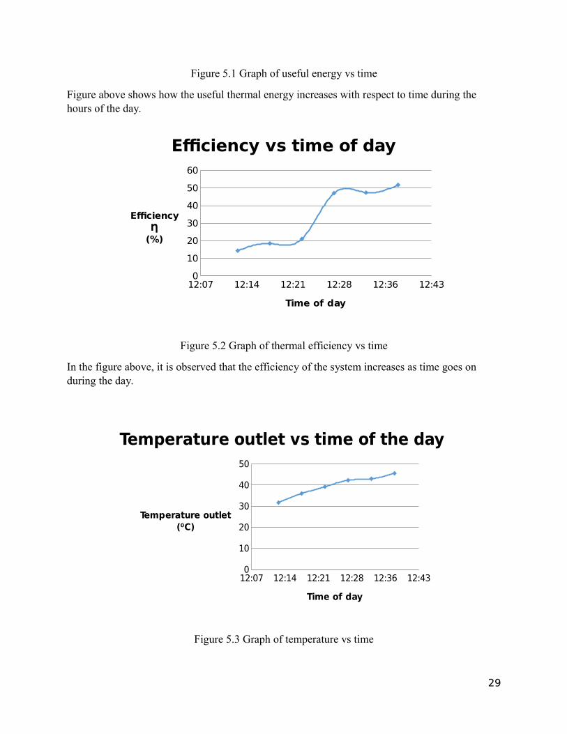
Figure 5.1 Graph of useful energy vs time
Figure above shows how the useful thermal energy increases with respect to time during the hours of the day.
12:07 12:14 12:21 12:28 12:36 12:430
10
20
30
40
50
60
Efficiency vs time of day
Time of day
EfficiencyȠ
(%)
Figure 5.2 Graph of thermal efficiency vs time
In the figure above, it is observed that the efficiency of the system increases as time goes on during the day.
12:07 12:14 12:21 12:28 12:36 12:430
10
20
30
40
50
Temperature outlet vs time of the day
Time of day
Temperature outlet(⁰C)
Figure 5.3 Graph of temperature vs time
29

The above graph shows the relation between temperature and time, as the time increases during the day with a constant flow rate, the temperature of the water increases as well.
10th January:
Calculations for the constant flow of water
Q=mwCpw (T w−T a )=Ƞ . ID . Aa
Where
mw = 0.004kg/s
V =0.4L/min
Temperature inlet= 20⁰C
Temperature outlet= 68.6⁰C
Temperature average= 44.3⁰C
Cpw average= 4181 (J /kgK )
Aa=¿ 1.2 m2
ID @12:20pm =920.5025cos 37 ⁰ = 1145.1
W /m ²¿ )
Q=mwCpw (T w−T a ) = 0.004 × 4178 × (68.6-20)= 812.6W
Q = Ƞ . ID . Aa
Ƞ=Q
I D . Aa= 59.1( )
The table below illustrates the results performed on the 10th of January 2016 during mid-day
Table 5.2 Results
Time Tempinlet (⁰C)
Tempoutlet(⁰C)
Aa Cpw avera
ge
θ(° ) ID
(
Qu
(W)
Ƞ
( )
30

(m2) (J /kgK ) W /m ²
)12:00 20 38.2 1.2 4179 32 2128.5 304.2 11.9
12:05 20 49.8 1.2 4179 33 2152.3 498.1 19.3
12:10 20 60.6 1.2 4179 35 2203.5 678.7 25.7
12:15 20 62.2 1.2 4179 36 1137.8 705.4 51.7
12:20 20 68.6 1.2 4180.0 36.5 1145.1 812.6 59.1
11:52 12:00 12:07 12:14 12:210
200
400
600
800
1000
Useful thermal energy vs Time of day
Time of day
Useful thermal energy � (W)
Figure 5.4 Useful energy vs time
Figure above depicts how the thermal energy increases with respect to time during the day as the sun shines..
31

11:5712:0012:0212:0512:0812:1112:1412:1712:2012:230
10
20
30
40
50
60
70
Efficiency vs Time of day
Time of day
EfficiencyȠ (%)
Figure 5.5 Thermal efficiency vs time
In the figure above, it is observed that the efficiency of the system increases as time goes on during the day.
11:52 12:00 12:07 12:14 12:210
20
40
60
80
Temperature outlet vs Time of day
Time of day
Temperature outlet(⁰C)
Figure 5.6 Temperature vs time
The above graph illustrates temperature vs time, the temperature increases with respect to time ofthe day.
32

5.4 Technical difficulties encountered
There were a few impediments to the effective conduct of the project, these included
workshop machining and operations. Most times the workshop was not always available at our
free periods but we managed to skip some classes and get the job done. Other difficulties
includes the machining of the different work parts we had to work with, it was not so easy as we
even got injured on some occasions but still the job had to be done. More so, during the testing/
experiment days we had difficulties in positioning the collector at the best possible point to
maximize power radiation intensity. And because also this had to be done outside of the
department with no shades provided we were sun-burnt most times but we are happy to have
gotten the job done.
5.5 Design improvement
After series of experiments and observations, the project had some errors which led to not having
good results at the end. Errors like reading the values, heat losses due to reflection on the heat
exchanger and calculation errors. To improve the project, insulation can be made with an
insulated cover on the heat exchanger so that when the sun rays reflects to the focal point where
the heat exchanger located there will be less heat loss to the environment.
33

CHAPTER 6
CONCLUSION AND FUTURE WORK
In conclusion, the main purpose of the project is to concentrate solar radiations at the
focus point of a parabolic dish reflector where the heat exchanger is located. To achieve this
goal, it was essential to get a uniform concentration so as to get the desired outlet temperature of
the water flowing through the heat exchanger. Written in this project is the mathematical
modeling of the system as well as equations to aid one to know how heat is generated and
dissipated through the system.
Nevertheless, this project can be modified in the future by applying some adjustments in the
system. Flat mirrors can be installed to be in front of the parabolic reflector and this intention
will aid the increase of concentration of solar radiation at the focus point. This is because the
reflected sun rays coming to the parabolic reflector are parallel to the principal axis. This type of
model is called on-axis model. The advantage of this system is that the absorber of the system
will not shade the parabolic reflector.
34

The temperatures generated in this project is high enough to be used in solar cooking
applications. Also, high water temperature from the heat exchanger can be used for heat systems
as well as to produce electricity using the organic Rankine cycle. Since this is a moving trend
around the globe in our today’s world, and bearing in mind that Cyprus has a huge amount of
sunlight radiation, these applications have to be reviewed in the nearest future to create a more
renewable means of generating energy.
REFERENCES
[1]A.C.Yunus. Heat Transfer a Practical Approach International edition. New York:
McGraw-Hill, 2002
[2]http://www.algebra.com/algebra/homework/word/travel/Travel_Word_Problems.faq.question.506661.html
[3]https://www.youtube.com/results?search_query=Roughly+30%25+of+this+radiation+is+reflected+back+to+space+
[4]http://www.egy.com/maadi/solar-energy.pdf
[5]https://en.wikipedia.org/wiki/Frank_Shuman
[6]https://en.wikipedia.org/wiki/Augustin_Mouchot
[7]https://www.google.com.tr/search?q=solar+parabolic+dish+collector&source=lnms&tbm=isch&sa=X&ved=0ahUKEwjbjtP8y6fKAhVlEXIKHaeDDoQQ_AUIBygB&biw=1517&bih=741&dpr=0.9#imgrc=VjX96g354k9FaM%3A
35

[8]http://www.newstrackindia.com/information/locations/Cyprus/518096-city-famagusta.htm
[9]http://www.pveducation.org/pvcdrom/properties-of-sunlight/declination-angle
[10]https://books.google.com.cy/books?id=R5slur_hdfEC&pg=PA132&lpg=PA132&dq=acceptance+angle+hsieh+1986&source=bl&ots=zX9mcEL0J1&sig=cuieaeiqOu-i-PLJHMJDcq9762Y&hl=en&sa=X&ved=0ahUKEwilgP3Hi6rKAhVD7XIKHaKVBxIQ6AEIIjAB#v=onepage&q=acceptance%20angle%20hsieh%201986&f=false
[11]https://books.google.com.cy/books?id=v_LfcIdJxIC&pg=PA126&lpg=PA126&dq=optical+efficiency+garg+and+prakash&source=bl&ots=3SLvsMsmYK&sig=Vpyy79qRQYDmlcZl9zOAsCc-8-4&hl=en&sa=X&ved=0ahUKEwiyiNjPjKrKAhXivHIKHR8RD-kQ6AEIJzAB#v=onepage&q=optical%20efficiency%20garg%20and%20prakash&f=false
[12]http://www.satsig.net/focal-length-parabolic-dish.htm
[13]http://www.ijera.com/papers/Vol2_issue1/EF021822830.pdf
[14]http://www.slideshare.net/SGhallab/steam-tables-fifth-edition-by-rogers-and-mayhew
[15]"ISO 9806-1:1994 - Test methods for solar collectors -- Part 1: Thermal performance of glazed liquid heating collectors including pressure drop". iso.org. 2012. Retrieved September 17, 2012.
[16]ISO 9806-2:1995. Test methods for solar collectors -- Part 2: Qualification test procedures. International Organization for Standardization, Geneva, Switzerland
[17]Julio Chaves, Introduction to Nonimaging Optics, CRC Press, 2008 [ISBN 978-1420054293]
[18]J.S.Hsieh. Solar Energy Engineering. Prentice Hall, 1986
[19]J.P.Holman. Heat Transfer 10th edition. New York: McGraw-Hill, 2010
[20]Kalogirou S. Solar Energy Engineering. California: Elsevier Inc. 2009. P.31-32
[21]Mojiri, Spectral beam splitting for efficient conversion of solar energy — A review,Renewable and Sustainable Energy Reviews Volume 28, December 2013, Pages 654–663,http://www.sciencedirect.com/science/article/pii/S1364032113005662
[22]Pol Duwez (1998). The Caltech Solar furnace. Retrieved December 16, 2014 from the World
[23]Wide Web: caltechs.library.caltech.edu/1597/1/Duwez.pdf
36
[24]"Solar Thermal Collectors in Polymeric Materials: A Novel Approach towards Higher Operating Temperatures - Springer". Springerlink.com. Retrieved 2013-08-20.
[25]Sandia (2005). Solar furnace in United States of America. Retrieved November 10, 2014 From the World Wide Web: http://www.sandia.gov/renewable_energy
[25]Tom Lane, Solar Hot Water Systems, Lessons Learned 1977 to Today p7
[26]"The Solar Keymark, The main quality label for solar thermal". estif.org. 2012.
Retrieved September 17, 2012.
[27]Wikipedia (2014). Solar furnace. Retrieved October 5, 2014 from the World Wide Web:
http://en.wikipedia.org/wiki/solar_furnace
[28]Vijaypratap R Singh et al Int. Journal of Engineering Research and Applications ISSN: 2248-
9622, Vol. 4, Issue 1(Version 1), January 2014, pp.216-220
[29] Wikipedia (2014). Solar furnace. Retrieved October 5, 2014 from the World Wide Web: http://en.wikipedia.org/wiki/solar_furnace
37
APPENDICES
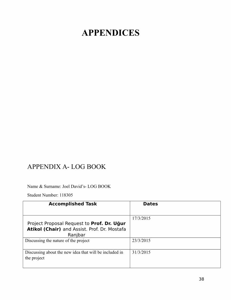
APPENDIX A- LOG BOOK
Name & Surname: Joel David’s- LOG BOOK
Student Number: 118305
Accomplished Task Dates
Project Proposal Request to Prof. Dr. UğurAtikol (Chair) and Assist. Prof. Dr. Mostafa
Ranjbar
17/3/2015
Discussing the nature of the project 23/3/2015
Discussing about the new idea that will be included in the project
31/3/2015
38

Conversing about the objective and scope of our project,learning more information’s on parabolic dish collectors
17/4/2015
Exchanging views on the measurements of the project devices
22/4/2015
Explanation on the preliminary design and methods of production
23/4/2015
Talking about the different sources to gather informationfrom
15/5/2015
Deliberating on material selections 21/5/2015
Completing design on solid works 18/6/2015
Finalizing thermal analysis and design calculations 20/6/2015
Selecting of dish and heat exchanger material 05/10/2015
Material analysis 10/10/2015
Manufacturing of first dish 17/10/2015
Manufacturing of the second dish 02/11/2015
Drawing of the heat exchanger with solid works 05/11/2015
Heat exchanger material selection and design 08/11/2015
39

Manufacturing of the heat exchanger 10/11/2015
Bending, drilling and soldering of copper pipes 05/12/2015
Putting aluminum foil on dish 08/12/2015
Joining heat exchanger to parabolic dish 23/12/2015
Writing of report 25/12/2015
Testing and result 06/01/2016
Reviewing all works 06/01/2016
MAYOWA’S LOG-BOOK
Student number: 118648
ACCOMPLISHED TASK DATES
PROJECT PROPOSAL REQUEST TO ASSIST. PROF. DR. TAHIR ABDUL HUSSAIN AND ASSIST PROF. DR. NERIMAN OZADA (VICE CHAIR)
17/03/2015
MEETING WITH THE SUPERVISOR 18/03/2015
ANALYZING THE PROJECT WITH TEAM MEMBERS
23/03/2015
EXCHANGING VIEWS ON THE DIMENSION OF THE PROJECT PARTS
30/04/2015
40

LITERATURE REVIEW 30/04/2015
WORKING ON THE GANTT CHART 20/06/2015
PREPARING MY LOG BOOK 20/06/2015
Selecting of dish and heat exchanger material 05/10/2015
Material analysis 10/10/2015
Manufacturing of first dish 17/10/2015
Manufacturing of the second dish 02/11/2015
Drawing of the heat exchanger with solid works 05/11/2015
Heat exchanger material selection and design 08/11/2015
Manufacturing of the heat exchanger 10/11/2015
Bending, drilling and soldering of copper pipes 05/12/2015
Putting aluminum foil on dish 08/12/2015
Joining heat exchanger to parabolic dish 23/12/2015
Writing of report 25/12/2015
Testing and result 06/01/2016
Reviewing all works 06/01/2016
41

Abdullah Awad log book
Student number: 138942
Choose the idea of the project with Assist.Prof. Dr. Tahir Abdul Hussain and Assist. Prof. Dr. Neriman Özada.
17/3/2015
Studying the main idea of the project and it goals. 20/3/2015
Get advises about how to work together to finish the project.
23/3/2015
Get some useful resources to gather information to clear any confusing in our mind.
25/3/2015
Asking some friends who are expert in solar power tostart well and avoid mistakes.
29/3/2015
Gathering what I got from all of previous resources and start work.
1/4/2015
Meeting with my group mates and each of us took his own chapter to do, we decide for me to work withcalculations.
3/4/2015
I searched for useful equations and give them to my advisor to check them and took the acceptance.
6/4/2015
I searched for different types of heat exchanger and put my assumption for designing the heat exchangerand the parabolic dish after that calculating the equations.
7/4/2015
I checked my first part for designing with my advisor and he accepted them with some modification about liquids and mass flow rate.
9\4\2015
I worked with second part of heat transfer and thermodynamic equations.
10/4/2015
I checked them with my advisor and take the acceptance.
13/4/2015
I met with my group mate to check what each of us has been done with his work.
20/4/2015
I searched for some resources to help me with drawing on solidworks.
7/5/2015
I draw the parabolic dish and check it with my group mate
10/5/2015
I draw the heat exchanger and facing some problemsand I took help with my solid works assistance.
15/5/2015
I checked all previous drawing with my advisor 18/5/2015
42
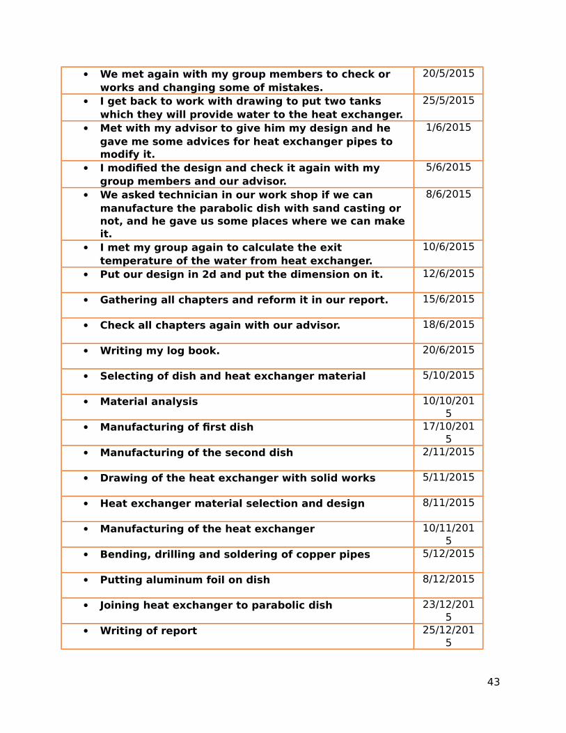
We met again with my group members to check or works and changing some of mistakes.
20/5/2015
I get back to work with drawing to put two tanks which they will provide water to the heat exchanger.
25/5/2015
Met with my advisor to give him my design and he gave me some advices for heat exchanger pipes to modify it.
1/6/2015
I modified the design and check it again with my group members and our advisor.
5/6/2015
We asked technician in our work shop if we can manufacture the parabolic dish with sand casting or not, and he gave us some places where we can make it.
8/6/2015
I met my group again to calculate the exit temperature of the water from heat exchanger.
10/6/2015
Put our design in 2d and put the dimension on it. 12/6/2015
Gathering all chapters and reform it in our report. 15/6/2015
Check all chapters again with our advisor. 18/6/2015
Writing my log book. 20/6/2015
Selecting of dish and heat exchanger material 5/10/2015
Material analysis 10/10/2015
Manufacturing of first dish 17/10/2015
Manufacturing of the second dish 2/11/2015
Drawing of the heat exchanger with solid works 5/11/2015
Heat exchanger material selection and design 8/11/2015
Manufacturing of the heat exchanger 10/11/2015
Bending, drilling and soldering of copper pipes 5/12/2015
Putting aluminum foil on dish 8/12/2015
Joining heat exchanger to parabolic dish 23/12/2015
Writing of report 25/12/2015
43

Testing and result 6/1/2016
Reviewing all works 6/1/2016
APPENDIX B-GANTT CHART
44

Selecting structural material
Material analysis
first dish manufacture
mnufacturing of second dish
solid works
heat exchanger andfinishing
continuation of heat exchanger
writing of report
testing and results
0 5 10 15 20 25
Start date
Days to complete
45
APPENDIX C
ENGINEERING DRAWING
46

Appendix D
http://students.emu.edu.tr/118305/
47