UAV = Unmanned Aerial Vehicle UAS = Unmanned Aircraft System
i
MENG 411 - Capstone Team Project
Eastern Mediterranean University
Faculty of Engineering
Department of Mechanical Engineering
Design and Fabrication of Solar UAV
Course Coordinator
Assist. Prof. Dr. Mostafa Ranjbar
Supervisor
Assoc. Prof. Dr. Qasim Zeeshan
Team Members
David Dangana 127341
Mazen Abdulrazik 127534
Yehia Jamaoui 138037
Group Name: Solarine
Capstone Team Project Spring 2015-2016
Date of Submission: 29-06-2016

ii
Jury Members
Names of jury members Signature
Assoc. Prof. Dr. Qasim Zeeshan (Supervisor)
Assist. Prof. Dr. Davut Solyalı
Assist. Prof. Dr. Murat Özdenefe

iii
Abstract
This report is about solar UAVs in general and the manufacturing of a small solar UAV as
Capstone team project in Eastern Mediterranean University. Engineers design solar UAVs for
many different purposes, and they have different classifications. The purpose of this report is to
give information about solar UAVs and the method used to make the design intended for the
project. There are three main sections in this report introduction, literature review including
information about solar energy, UAVs, solar UAVs, history and classifications of UAVs, and the
design and configuration of the solar UAV required for the project.
Key words: Solar powered UAV, Solar Energy, Solar Airplane

iv
Table of Content
List of Figures………………………………………………………………………………...vii
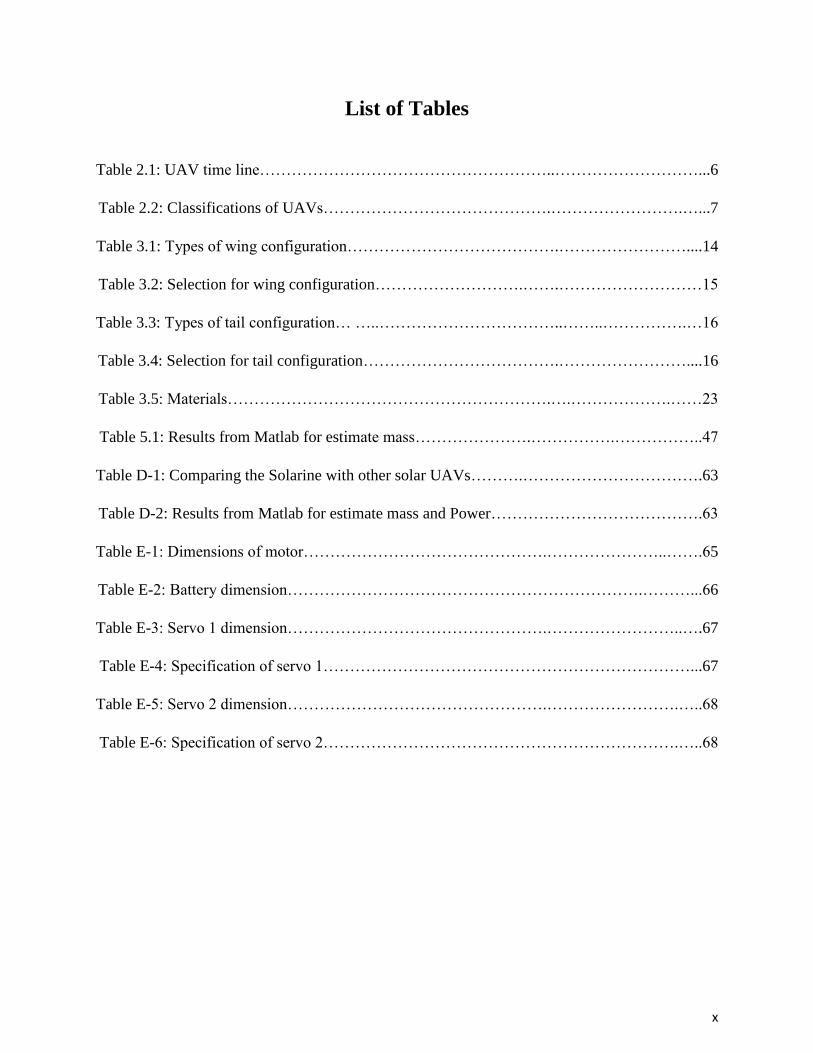
List of Tables……………………………………………………………………………………x
List of symbols……………………………………………………………………………..…..xi
1 Introduction………………………………………………………………………………..1
1.1 Importance of Solar UAVs…………………………………………………………….1
1.2 Summary of the Problem………….………..………………………………………….1
1.3 Objective…………………….….……………………..……………………………….2
1.4 Report Organisation…………………………………..………………………………..2
2 Literature Review………………………………………………………………………….3
2.1 Solar Power…………………………………………………………………………......3
2.2 Photovoltaic Cell………………………………………………………………………..3
2.3 Unmanned Aerial Vehicle (UAV)………..…………………………………………….5
2.4 History of UAV and Timeline…………………………………………………………5
2.5 Classification of UAV………………………………………………………………….7
2.5.1 Micro and Mini UAVs………………………………………………............….8
2.5.2 Tactical UAVs……………………………………………………………….….8
2.5.3 Strategic UAVs…………………………………………………………………9
2.6 Solar Flight……………………………………………………………………….……10
2.6.1 Large and Medium Solar Aircraft……………………………………………….10
2.6.2 Small Solar Aircrafts…………………………………………………………….12
3 Design and Configuration…………………………………………………………………14
3.1 Configuration…………………………………………………………………………..14
3.1.1 Wing Configuration……………………………………………………………..14
3.1.2 Tail Configuration………………………………………………………………15
3.2 Solar Irradiation………………………………………………………………………..17
3.3 System Breakdown Structure……….………………………………………………....19
3.4 Power and Mass Estimates……………………..……………………………………...20
3.4.1 The Power Available…………………………………………………………...20
3.4.2 Fixed Mass……………………………………………………………………...20

v
3.4.3 Mass of Airframe……………………………………………………………….20
3.4.4 Mass of Solar Cells…………………………………………………………........21
3.4.5 Mass of Batteries………………………………………………………………….21
3.4.6 Mass of Propeller……….…………………………………………………..…….21
3.5 Design Methodology and Application………………………………………...................22
3.6 Air Frame Structure……………………………………………………….…………....23
3.6.1 Structural Materials………………………………………………….…………....23
3.6.2 Structural Mass………………………………………………………………..….23
3.7 Airfoil Selection……………………………………………………………………….....24
3.7.1 Airfoil Analysis with XFLR5…………………………………………....…….....24
3.8 Empennage Configuration………………………………………………………….…....27
3.8.1 Empennage Analysis with XFLR5…………………………………………….....28
3.9 Fuselage Design………………………………………………………………….....…....30
3.10 Electrical Components………………………………………………….…….....31
3.10.1 The Propeller……………………………………………………………….…......31
3.10.2 Motor……………………………………………………………………………...31
3.10.3 Electric Speed Controllers (ESC)...…………………………………………….....31
3.10.4 Servos……………………………………………………………………………..32
3.10.5 Batteries……………………………………………………………………….….32
3.10.6 Solar panels………………………………………………………………….…....33
3.10.7 Transmitters……………………………………………………………………....33
3.10.8 Cost analysis……………………………………………………………………...35
4 Manufacturing and Testing…………………………....…………………………………....36
4.1 Model 1 Manufacturing Process…………………………………………………………36
4.1.1 The Wing……………………………………………………………………….…36
4.1.2 The fuselage……………………………………………………………………....38
4.1.3 The Tail………………………………………………………………………...…39
4.2 Model 2 Manufacturing Process………………………………………………… ……...40
4.3 Solar Cells……..…………………………………………………………………………41
4.4 Assembly Process………………...………………………………………………………42
4.5 Testing……………………………………………………………………………………44
4.5.1 Electrical Components Testing…………………………………………………..44
4.5.2 Flight Test for Model 1…………………………………………………………..46
4.5.3 Flight Test for Model 2…………………………………………………………..47

vi
5 Results and Discussion...……………………………………………………………………....48
6 Conclusion…………………………………………….……...………………………………..50
APPENDICES………………………………………………………………………………..51
APPENDIX A- Log Books (Individual Contribution…..…………………………………....51
APPENDIX B- GANTT CHART………………………………………………………..…..57
APPENDIX C- DESIGN………………………………………………………………….…58
APPENDIX D…………………..............................................................................................64
APPENDIX E – Equipment List and code...............................................................................65
REFERENCES…………………………………………………………………………….…80

vii
List of Figures
Figure 2.1: Photovoltaic cell solar panel …………..…...……………………………………...….4
Figure 2.2: Black Widow mini UAV …………….……..………………………………………...8
Figure 2.3: Bayraktar tactical UAV …….………………....…………………………...…………9
Figure 2.4: Global Hawk Strategic UAV …..………………....………………………...................9
Figure 2.5: Pathfinder solar UAV ………...………………….…..…………………….…….….10
Figure 2.6: Helios solar UAV……………….………………….….……………………….…....11
Figure 2.7: Sky-Sailor small solar UAV …………...………….….…………………………..…12
Figure 2.8: Sun Surfer small solar UAV….…………...………….…..…………...……………..13
Figure 3.1: The irradiation horizontal global map of Cyprus.....…….….….……..……………..17
Figure 3.2: Global horizontal radiation map Cyprus………….…..……….……..……………….18
Figure 3.3: Continuous monthly global horizontal radiation map of Cyprus...................………19
Figure 3.4: System breakdown structure……………………………………………...…………19
Figure 3.5: Conceptual design graphs for different aspect ratios……………………….......…...22
Figure 3.6: Total mass of solar aircraft against wingspan………………………………...……..22
Figure 3.7: NACA0015 Aerofoil ……………………………………………………………......24
Figure 3.8: XFLR5 Reynolds numbers ………………………………………………….…........24
Figure 3.9: Lift-to-Drag Ratio against Angle of Attack for NACA001………………...……….25
Figure 3.10: Lift Coefficient against Angle of Attack for NACA0015..………………..…….....25
Figure 3.11: Lift Coefficient against Drag Coefficient for NACA0015…....................................26
Figure 3.12: Moment Coefficient against Angle of Attack for NACA0015.................................26
Figure 3.13: XFLR5 Reynolds numbers…………………………………...…….…....................28
Figure 3.14: Lift Coefficient against Drag Coefficient for NACA0008……................................28
Figure 3.15: Lift Coefficient against Angle of Attack for NACA0008……………………..…...29
Figure 3.16: Moment Coefficient against Angle of Attack for NACA0008…………..………...29

viii
Figure 3.17: Lift-to-Drag Ratio against Angle of Attack for NACA0008..……………..………30
Figure 3.18: Electric speed controller…………………………………………………...………32
Figure 3.19: Tx mode 1………...………………………………………………………...………33
Figure 3.20: Tx mode 2……………………………………………...………………………...…34
Figure 3.21: Tx mode 3……………………………………………...………………………...…34
Figure 3.22: Tx mode 4………………………………………………...……………………...…34
Figure 3.23: Cost analysis………………………………………………………...…………………………….35
Figure 4.1: Ribs from balsa wood………………………………………………………………..36
Figure 4.2: Cut ribs for placing spar……………………………………………………………..36
Figure 4.3: Spacing of ribs……………………………………………….………………………37
Figure 4.4: Leading edge……………………………………………………………………...…37
Figure 4.5: Installed ailerons……………………………………………………..………………37
Figure 4.6: Fuselage structure…………………………………………………….……………...38
Figure 4.7: Fuselage and carbon fiber pipe…………………………………….……………...…38
Figure 4.8: Stabilize, fin and carbon fiber pipe………………………………………………….39
Figure 4.9: Installation of elevator and rudder………………………………….………………..39
Figure 4.10: Model 2……………………………………………………………………………..40
Figure 4.11: Connected solar cells…………………………………………………..…………...41
Figure 4.12: Assembly tree………………………………………………………...…………….42
Figure 4.13: Mounting of motor………………………………………………………………...42
Figure 4.14: Installation of electrical components in fuselage……………………..…………....43
Figure 4.15: Motor testing………………………………………………………….……………44
Figure 4.16: Servos to ailerons………………………………………………………….……….44
Figure 4.17: Solar cells in series and parallel………………………….………………………...45
Figure 4.18: Solar unmanned vehicle………………………………….………………………...45
Figure 4.19: Flight take-off………………………………………………………………………46
Figure 4.20: Failed take-off…..………………………………………………………………….46
Figure 4.21: 2nd model flight take-off……………………………………………………………47

ix
Figure 4.22: Flight stall in the second model…………………………………………………….47
Figure C-1: Full assembled model……………………………………………………………….62
Figure C-2: Individual parts for assembly……………………………………………………….62
Figure D-1 Specifications of Cyanoacrylate Glue ……………………….……………………...63
Figure E-1: Motor………………………………………………………………….…………….64
Figure E-2: Motor dimension…………………………………………………………….……...65
Figure E-3: Propeller………………………………………………………………….…………65
Figure E-4: Battery…………………………………………………………………….………...66
Figure E-5: Battery Dimension………………………………………………………………….66
Figure E-6: Electronic speed controller…………………………………………………………66
Figure E-7: Servo 1 dimension……………………………………………................………….67
Figure E-8: Servo 2 dimension………………………………………………………………….68
Figure E-9: Solar cell…………………………………………………………………………....69
x
List of Tables
Table 2.1: UAV time line………………………………………………..………………………...6
Table 2.2: Classifications of UAVs…………………………………….…………………….…...7
Table 3.1: Types of wing configuration………………………………….……………………....14
Table 3.2: Selection for wing configuration……………………….…….………………………15
Table 3.3: Types of tail configuration… …..……………………………..……..…………….…16
Table 3.4: Selection for tail configuration……………………………….……………………....16
Table 3.5: Materials…………………………………………………….….……………….……23
Table 5.1: Results from Matlab for estimate mass………………….…………….……………..47
Table D-1: Comparing the Solarine with other solar UAVs……….…………………………….63
Table D-2: Results from Matlab for estimate mass and Power………………………………….63
Table E-1: Dimensions of motor……………………………………….…………………..…….65
Table E-2: Battery dimension………………………………………………………….………...66
Table E-3: Servo 1 dimension………………………………………….……………………..….67
Table E-4: Specification of servo 1……………………………………………………………...67
Table E-5: Servo 2 dimension………………………………………….…………………….…..68
Table E-6: Specification of servo 2………………………………………………………….…..68

xi
List of symbols
Aspect Ratio AR
Area of solar cell Asc
Wingspan b
Wing Drag Coefficient CD
Wing Lift Coefficient CL
Chord Length c
Propeller Diameter Dp
BEC (Step-down) Efficiency ɳbec
Efficiency of Cambered ɳcbr
Efficiency of Battery Charging ɳchrg
Efficiency of Motor Controller ɳctrl
Efficiency of Battery Discharging ɳdchrg
Efficiency of Gearbox ɳgrb
Efficiency of Motor ɳmot
Efficiency of Maximum Power Point Tracker ɳmppt
Efficiency of Propeller ɳplr
Efficiency of Solar Cell ɳsc
Efficiency of Weather ɳwthr
Fuselage Length FL
Acceleration due to Gravity g
Energy Density of Battery kbat
Mass/Power Ratio of Propulsion Group kprop
Solar Cell Mass Density ksc
Airframe Constant kaf
Total Mass of Aircraft m
Total Mass of Airframe maf
Total Mass of Avionics mavc

xii
Total Mass of Batteries mbat
Fixed Mass mfixed
Total Mass of Payload mpld
Total Mass of Propulsion Group mprop
Total Electrical Power Available Pelectot
Power Required for Steady Level Flight Plevel
Density of Air p
Total Empennage Side Area St
Tail Aperture α
Total Day Time Tday
Total Night Time Tnight
Aircraft Velocity V

1
Chapter 1
Introduction
The aviation industries are continuously developing from the invention of the first plane till
today. There are different types of aircraft present to which could include airplane, helicopters,
unmanned aerial vehicles(UAV) etc. this various aircrafts have moved from the stage of being
driven by a human inside them to the stage of being controlled by a controller device outside them,
and in some cases by developed program to help them control themselves. They have also
diversified to have more than one power source that includes solar energy and an electrical source;
these kinds of aircrafts are called hybrids. This capstone project would be capitalizing on the
modern development on the hybrid energy sources to develop a UAV.
1.1 Importance of Solar UAVs
The ability for an aircraft to fly for a long period of time has become an important issue and
a target of research. The UAVs have been of important use for both civilian and military
applications. The required endurance is in the range of a couple of hours in the case of law
enforcement, border surveillance and forest fire fighting. However, other applications require high
altitudes, such as communication platform for mobile devices, weather research and forecast,
environmental monitoring, would require remaining airborne during, weeks or even months. The
only way possible currently to reach such endurances is through solar powered UAVs.
1.2 Summary of the Problem
The ability of an UAV to fly for long periods of time has become an important issue and
target of research. These researches are increasingly taking importance in our society and world,
for civilian and military applications. In case of military application the required endurance is just
a couple of hours where it ca be used for border surveillance, forest fire fighting or power line
inspection. However, other applications at high altitudes, such as communication platform for
mobile devices, weather research and forecast, environmental monitoring, would require
remaining airborne during days, weeks or even months. Until this moment, the only possible way

2
to reach these kind of goals is using solar powered UAVs. Solar cells which are integrated into
one panel is used to collect energy from the sun and power the propulsion unit and other
instruments, the other part being stored for the night time. In order to reach the target endurance,
the design of the airplane has to be thought very carefully, as a system composed of many
subsystems that are continuously exchanging energy. Due to these relationships, each part has to
be sized accordingly to all the others.
1.3 Objectives
The objective of this project is to develop an RC unmanned aerial vehicle, which is powered
by solar energy in conjunction with a battery system, using flexible solar photovoltaic cells as the
main source of electric energy generation in the UAV and also with an aim of developing a cost
efficient design of the hybrid unmanned aerial vehicle.
1.4 Report Organistaion
The report would give information about solar energy and unmanned aerial vehicle in the
2nd chapter and in the 3rd chapter; information such as dimensioned drawing, cost analysis,
materials and manufacturing methodology would be discussed. In the 4th chapter a step by step
manufacturing process and assembling will be explained and the testing process of the final model
would be discussed. The 5th chapter includes the results of testing and discussion of the project
and will contain ideas to make the project more efficient of sustainable. The last chapter includes
the conclusion and future work. In conclusion the project would be achieved with the theoretical
knowledge and basic skills obtained by the students all through their educational life in the field
of mechanical engineering.

3
Chapter 2
Literature Review
2.1 Solar Power
Solar power is energy from the sun that is converted into thermal or electrical energy. Solar
energy is the cleanest and most abundant renewable energy source available. Using the technology
present this energy can be harnessed for many uses such as generating electricity, providing light
and heating water for domestic, commercial or industrial use. Solar energy can be harnessed using
photovoltaic, solar heating and cooling, concentrating solar power and passive solar. The first three
forms are called active solar systems and they use mechanical or electrical devices to convert the
sun light into other useful forms. Passive solar buildings are designed and oriented to collect, store,
and distribute the heat energy from sunlight to maintain the comfort of the occupants without the
use of moving parts or electronics. Solar power plants can be built as distributed generation located
at or near the point of use, or as a central-station [2].
2.2 Photovoltaic Cell
Photovoltaic (PV) cells are made up of at least 2 semi-conductor layers. As shown in figure
2.1 the first layer contains the positive charge, and the second the negative charge. Sunlight
contains little particles of solar energy called photons. As a photovoltaic cell comes in contact with
sunlight, many of the photons are reflected, passes through, or immersed into the solar cell. When
adequate amount of photons are absorbed into the negative layer of the photovoltaic cell, electrons
are released from the negative semiconductor material. Owing to the manufacturing procedure of
the positive layer, the released electrons migrate to the positive layer generating a voltage
differential, similar to a household battery. When the two layers are connected to a load, the
electrons flow through the circuit generating electricity. All individual solar energy cell produces
only 1-2 watts. In other increase power output, cells are jointed in a weather-tight package called
a solar module. These modules, from one to hundreds or thousands are then connected in series or

4
parallel to one another, which are then called a solar array, to create the anticipated voltage and
amperage output required by the given project [3].
Figure 2.1: Photovoltaic cell solar panel adapted from [32]
Negative layer
Positive layer

5
2.3 UAV
The UAV is an abbreviation for Unmanned Aerial Vehicle, it is an aircraft without a pilot.
UAVs are also remote controlled aircraft (e.g. usually flown by a pilot from a control station) or
can fly by itself based on flight programmed plans or more autopilot systems [4]. Unmanned aerial
vehicle have has been in existence since the early 1900s, the first unmanned aerial vehicles built
were used by the military during wars to pick and drop bombs on targets, but the unmanned aerial
vehicle made had flaws such and missing the target or in controlling them.
Modern day unmanned aerial vehicle have advanced to more sophisticated machines which
are both used by military and civilian, they have become very important in areas such as
surveillance, military defense, news broadcasting etc. and in the future they would become of more
importance to the world.
2.4 History of UAV and Time line
Unmanned aerial vehicles (UAVs) were first used during the American Civil War, an inventor
patented an unmanned balloon that carried explosives that could be dropped after a time-delay fuse
mechanism triggered the basket to overturn its contents. Air currents and weather patterns made it
difficult to estimate for how long to set the fuse, and the balloon was never successfully deployed.
In 1883, the first aerial photograph was taken using a kite, a camera and a very long string attached
to the shutter-release of the camera. In 1898, this technology was put to use in the Spanish-
American War, resulting in the first military aerial reconnaissance photos.
World war I was when the first radio controlled unmanned aerial vehicle were developed
but unfortunately where not used until the end of the war [5]. A time line of the various unmanned
aerial vehicle developed from the table given below:

6
Table 2.1: UAV Time Line adapted from [6]
Time line Description Inventions
1910s
The first UAV took flight in the U.S. The success of
UAVs in test flights was huge. Armistice arrived
before the prototype UAVs could be deployed in
earnest.
Sperry Aerial
Torpedo (USA).
Kettering Aerial
Torpedo (USA).
1930s
For more than a decade after the end of World War I,
development of pilotless aircraft in the U.S. and
abroad declined sharply. By the mid-to-late 1930s,
new UAVs emerged as an important combat training
tool.
DH.82B Queen Bee
(UK).
Radio Planes (USA).
1940s
During World War II, Nazi Germany's innovative V-1
demonstrated the formidable threat a UAV could pose
in combat. America's attempts to eliminate the V-1
laid the groundwork for post-war UAV programs in
the U.S.
V-1 (Germany).
PB4Y-1 and BQ-7
(USA).
1960s
From their early use as target drones and remotely
piloted combat vehicles, UAVs took on a new role
during the Vietnam War: stealth surveillance.
AQM-34 Ryan
Firebee (USA)
D-21 (USA)
1970s
The success of the Firebee continued through the end
of the Vietnam War. In the 1970s, while other
countries began to develop their own advanced UAV
systems, the U.S. set its sights on other kinds of
UAVs.
Ryan SPA 147
(USA)
1980s
During the late 1970s and throughout the 1980s, the
Israeli Air Force, an aggressive UAV developer,
pioneered several important new UAVs, versions of
which were integrated into the UAV fleets of many
other countries, including the U.S.
Scout (ISRAEL)
Pioneer(ISRAEL)
1990s to Present day
UAVs command a permanent and critical position in
high-tech military arsenals today, from the U.S. and
Europe to Asia and the Middle East. They also play
peaceful roles as monitors of our Earth's environment.
Darkstar (USA).
Pathfinder (USA).
Helios (USA). Etc.
7
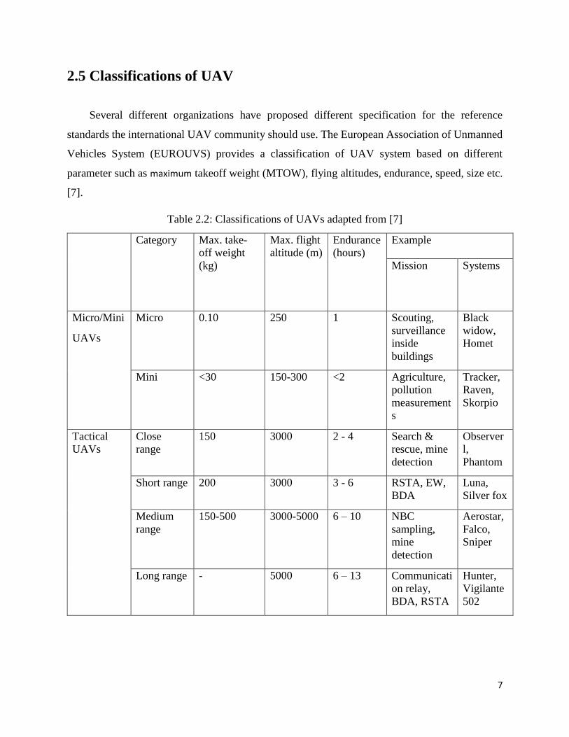
2.5 Classifications of UAV
Several different organizations have proposed different specification for the reference
standards the international UAV community should use. The European Association of Unmanned
Vehicles System (EUROUVS) provides a classification of UAV system based on different
parameter such as maximum takeoff weight (MTOW), flying altitudes, endurance, speed, size etc.
[7].
Table 2.2: Classifications of UAVs adapted from [7]
Category Max. take-
off weight
(kg)
Max. flight
altitude (m)
Endurance
(hours)
Example
Mission Systems
Micro/Mini
UAVs
Micro 0.10 250 1 Scouting,
surveillance
inside
buildings
Black
widow,
Homet
Mini <30 150-300 <2 Agriculture,
pollution
measurement
s
Tracker,
Raven,
Skorpio
Tactical
UAVs
Close
range
150 3000 2 - 4 Search &
rescue, mine
detection
Observer
l,
Phantom
Short range 200 3000 3 - 6 RSTA, EW,
BDA
Luna,
Silver fox
Medium
range
150-500 3000-5000 6 – 10 NBC
sampling,
mine
detection
Aerostar,
Falco,
Sniper
Long range - 5000 6 – 13 Communicati
on relay,
BDA, RSTA
Hunter,
Vigilante
502

8
2.5.1 Micro and Mini UAVs
Small aircrafts include micro and mini UAVs that fly at a low altitude of 300m. These types
of UAVs can be used for surveillance inside buildings or flying in small areas, they can also be
used for recording and listening. Example of micro and mini UAVs are BlackWidow (figure 2.2),
Carina-Mini ARF etc.
Figure 2.2: Black Widow Mini UAV obtained from [21]
2.5.2 Tactical UAVs
This kind of UAVs are more bigly compared to the micro and mini UAVs, they also fly at a
higher altitude ranging for from 3,000 to 8,000 meters. They are used by the military in the
following applications
Border patrol
Surveillance high value assets
Target Acquisition

9
Examples of Tactical UAVs includes Bayraktar (figure2.3), Shadow, etc
Figure 2.3: Bayraktar Tactical UAV obtained from [22]
2.5.3 Strategic UAVs
They are UAVs with high endurance and maximum high altitudes of about 20,000 meters,
they are usually fully automated which includes its landing and takeoff. This type of UAVs are
usually controlled from the ground know as ground control station (GCS). They are you in different
fields one of which is airport security, examples includes Global Hawk (figure2.4), Raptor etc.
Figure 2.4: Global Hawk Strategic UAV obtained from [23]

10
2.6 Solar Flight
The concept of the solar flight is flying the aircraft with solar energy as a source of generating
power. From the first invention of a solar aircraft in 1974 many other solar aircrafts has been made,
they vary is shapes and sizes but all having same concept. Based on their sizes we can categorize
them into two
2.6.1 Large and medium solar aircraft
They are solar aircraft with very large wingspan and mass, they also operate on high altitude
some examples are
a) Pathfinder
The pathfinder is a project of NASA which could produce a maximum of 8,000W from its solar
cells, it weighed 286lb and had a wingspan of 98ft. In 1995 the pathfinder sets first altitude record
for solar powered aircraft at 50,000ft during 12hours of flight. Its configuration is as that of a flying
wing with six propellers, three on the right and on the left of the aircraft which uses an LA2573A
airfoil [8].
Figure 2.5: Pathfinder solar UAV obtained from [23]

11
b) Helios
The Helios was the largest solar powered aircraft made by NASA it has a wing span of 247ft
weight over 2,000lb and photovoltaic array capturing of about 42KW of solar power, it also had
a maximum altitude of 96,500ft in 2001. But unfortunately for the project during its flight test in
2003 it crashed into the Pacific Ocean and was destroyed. It has a better version of the pathfinder
with almost similar configuration but differed in the number of propellers, it had 10 propellers
five on the right and on the left [9].
Figure 2.6: Helios solar UAV obtained from [24]

12
2.6.2 Small solar aircrafts
They differ from the large and medium UAV because of their small sizes and lower flying
altitudes examples includes
a) Sky-Sailor
It is a small solar UAV designed by Andre Noth, it has a wing span of 3240mm and a width
of 1818mm and a flying altitude of 500m. It has a configuration of a v-tail and its wings above
the fuselage (high wing). The solar cell are placed on the wing because of its area, the aircraft is
made up of balsa wood and some composite materials, the wing was designed while the tail uses
an NACA0008 airfoil.
Figure 2.7: Sky-sailor small solar UAV obtained from [12]

13
b) Sun-Surfer:
The sun surfer MAV was designed with the purpose of carrying 20 grams of payload
and be able of flying continuously in good weather conditions. The sun Surfer has a wing
span of 0.8m and a total mass of 0.126kg. It has a T-tail configuration and an airfoil similar
to that of the Sky-Sailor.
Figure 2.8: Sun Surfer small solar UAV obtained from [13]

14
CHAPTER 3
Design and Configuration
3.1 CONFIGURATION
3.1.1 Wing Configuration
The configurations of UAV’s may differ from one to another, but choosing the best
configuration would be based on some factors such as stability, robustness of the structure,
design simplicity, weight, maximum lift. There are different types of wing configurations,
Table 3.1 Types of wing configuration adapted from [10]
Type of wing Configuration
High wing
A high wing is typically any plane that has the
main wing mounted on the top of the fuselage.
This configuration is favored for training
purposes because it offers more stability at
slower speeds and a tendency to right itself,
allowing a beginner more room for error manufacturing difficulty: Easy
Mid wing
Mid-wing planes are typically very well
balanced and offer much bigger control
surfaces makes them highly maneuverable
and predictable in their flight characteristic manufacturing difficulty: medium
Low wing
Generally the wing has a more pronounced
dihedral to give it more stability in turns and
help prevent stalling at slower speeds. They
do show more of a tendency to want to lose
altitude in a turn, requiring more coordinated
elevator
manufacturing difficulty: hard
Flying wing
With the lack of a rear stabilizer, flying wings
are very quick to change pitch and can also
roll very fast. Not for the typical beginner
manufacturing difficulty: hard

15
For the design of the solar UAV we would be selecting the high wing configuration
because of its simplicity.
Evaluation Scale for Pugh’s matrices
+ = strongly meets selection criteria
0 = neutrally meets selection criteria
- = does not meet selection criteria
Table 3.2: Selection criteria for wing configuration
High Wing Mid Wing Low Wing Flying Wing
Stability + + + -
Manufacturing + 0 - -
Assembly + 0 - +
Sum + 3 1 1 1
Sum 0 0 0 0 0
Sum - 3 0 -2 -2
Net 3 1 -1 -1
Rank T1 T2 T3 T3
Continue? Yes Yes No No
3.1.2 Tail Configuration
The tail is a vital part of the aircraft its selection is based on deferent parameters
including stability, weigh etc. There are also different tail configurations which are
16
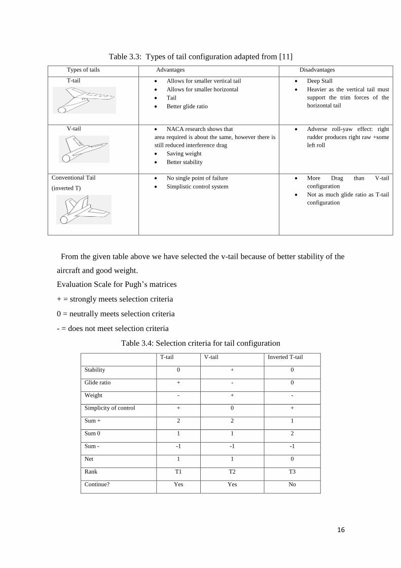
Table 3.3: Types of tail configuration adapted from [11]
Types of tails Advantages Disadvantages
T-tail
Allows for smaller vertical tail
Allows for smaller horizontal
Tail
Better glide ratio
Deep Stall
Heavier as the vertical tail must
support the trim forces of the
horizontal tail
V-tail
NACA research shows that
area required is about the same, however there is
still reduced interference drag
Saving weight
Better stability
Adverse roll-yaw effect: right
rudder produces right raw +some
left roll
Conventional Tail
(inverted T)
No single point of failure
Simplistic control system
More Drag than V-tail
configuration
Not as much glide ratio as T-tail
configuration
From the given table above we have selected the v-tail because of better stability of the
aircraft and good weight.
Evaluation Scale for Pugh’s matrices
+ = strongly meets selection criteria
0 = neutrally meets selection criteria
- = does not meet selection criteria
Table 3.4: Selection criteria for tail configuration
T-tail V-tail Inverted T-tail
Stability 0 + 0
Glide ratio + - 0
Weight - + -
Simplicity of control + 0 +
Sum + 2 2 1
Sum 0 1 1 2
Sum - -1 -1 -1
Net 1 1 0
Rank T1 T2 T3
Continue? Yes Yes No

17
3.2 Solar Irradiation
The irradiation horizontal global map of Cyprus is based on the data obtained from
April 2004 to March 2010 on a year’s average sunshine provided by solarGIS database
[26] shown in figure 3.1.
Figure 3.1: The irradiation horizontal global map of Cyprus is based on the data
obtained from April 2004 to march 2010. Adapted from [26]
Solar radiation on the horizontal surface received annually in Cyprus is 1725KWh/m2
per year. About 69% direct solar radiation reaches the surface which give a value of
1188KWh/m2, and a diffuse radiation of 31% equaling the value of 537KWh/m2 [27].

18
Cyprus global horizontal radiation weather data is shown in figure 3.2. It identifies the
global radiation all through the year per hour of all days of the month. As shown in the
figure, in the summer the global radiation peaks during midday with a radiation of
1000W/m2 [25].
Figure 3.2: Global horizontal radiation map Cyprus obtained from [25]
From figure 3.3 we can notice the global horizontal radiation has its lowest values at
the winter period of about 450W/m2 and continuously increase towards the summer and
reaches the maximum during June and July to about 950W/m2. Also shown in figure 3.3
the drop in irradiance during the winter and autumn periods the sky becomes cloudier
causing shadows which would lead to a drop of efficiencies of the solar cells. We are
going to consider two parameters in the model, the maximum irradiance Imax and Tday the
duration of the day. The area under the curve is the daily solar energy per square meter
which would be calculated using the equation (3.0). ɳwthr is a constant for cloudy days
with values 1 for a clear day and 0 for darkness [12].

19
Figure 3.3: Continuous monthly global horizontal radiation map of Cyprus obtained
from [25]
Eday density = 𝐼𝑚𝑎𝑥𝑇𝑑𝑎𝑦
𝜋2⁄
ɳwthr (3.0)
The values of Imax and Tday are obtained from the figures above, that gives information
about our location which is Cyprus.
3.3 System Breakdown Structure
Figure 3.4: System breakdown structure

20
3.4 Power and Mass Estimation model
Mass model estimation is a good means to calculate the total mass m of the aircraft,
we would also perform some calculations which would allow us obtain estimate of the
power required for flight and finally achieve an estimate of the total area occupied by the
solar cells on the aircraft the various equations need would be obtained from A. Noth’s
design of solar powered airplane for continuous flight [12].
3.4.1 Power Available
For the power available we have to consider the lift and drag force which are the
most important forces for calculation we use the equation
L = CL 1
2 pV2 S (3.1)
D = CD 1
2 pV2 S (3.2)
The lift force is also equal to the weight and the drag to thrust. In a steady air flight
the velocity can be then calculated using the equation
V = √2mg
𝑝𝑆𝐶𝑙 (3.3)
For the power Plevel = TV
Plevel = CD
CL3
2⁄ √
2AR𝑔3
𝑝 𝑚
32⁄
𝑏 (3.4)
3.4.2 Fixed Mass
From Noth’s mass prediction model the fixed mass can be calculated
mfixed = mav + mpld (3.5)
3.4.3 Mass of Airframe
Noth uses a statistical analysis to show how the airframe mass depends on the aspect
ratio and wingspan of the aircraft. He then chooses constants
maf = kaf ARx2bx1 (3.6)

21
The constants x1 and x2 will remain the same as in Noth’s models
3.4.4 Mass of Solar Cells
To obtain the mass of solar cells we first have to determine the area of the solar cells
on the aircraft by using the Noth’s equation below
Asc= 𝜋
2ɳ𝑠𝑐ɳ𝑐𝑏𝑟ɳ𝑚𝑝𝑝𝑡I𝑚𝑎𝑥ɳ𝑤𝑡ℎ𝑟(1 +
T𝑛𝑖𝑔ℎ𝑡
T𝑑𝑎𝑦
1
ɳ𝑐ℎ𝑟𝑔ɳ𝑑𝑐ℎ𝑟𝑔
) Pelectot (3.7)
To calculate for
Pelectot = 1
ɳ𝑐𝑡𝑟𝑙ɳ𝑚𝑜𝑡ɳ𝑔𝑟𝑏ɳ𝑝𝑖𝑟 Plevel +
1
ɳ𝑏𝑒𝑐 ( Pav + Ppld ) (3.8)
Then collecting the values of irradiation we can calculate the mass by
msc = Asc ( ksc + kenc ) (3.9)
3.4.5 Mass of Batteries
mbat = 𝑇𝑛𝑖𝑔ℎ𝑡
ɳ𝑑𝑐ℎ𝑟𝑔𝑘𝑏𝑎𝑡 Pelectot (3.10)
3.4.6 Mass of Propeller
It consists of various parts and could be obtained using the below equation
mprop = kprop Plevel (3.11)
22
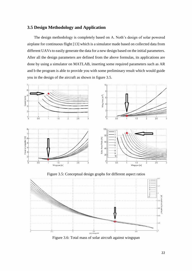
3.5 Design Methodology and Application
The design methodology is completely based on A. Noth’s design of solar powered
airplane for continuous flight [13] which is a simulator made based on collected data from
different UAVs to easily generate the data for a new design based on the initial parameters.
After all the design parameters are defined from the above formulas, its applications are
done by using a simulator on MATLAB, inserting some required parameters such as AR
and b the program is able to provide you with some preliminary result which would guide
you in the design of the aircraft as shown in figure 3.5.
Figure 3.5: Conceptual design graphs for different aspect ratios
Figure 3.6: Total mass of solar aircraft against wingspan

23
The above graph results from the matlab software which was analyzed to
determine the final design concept. From the combination of all the results which includes
speed, wing area, power of propulsion etc. the most suitable wingspan ranges from 0.6m
to 1.3m which is in the range of a small wing. A problem related to small wingspan is that
the solar area ratio would be large, making it more complex compared to large wingspan
aircraft. The most suitable aspect ratios lies between 5 and 8. Below 5 the wing area
becomes significantly larger while above 12 it requires a high percentage of solar cell.
3.6 Air frame structure
3.6.1 Structural materials
The materials used for the fabrication of the UAV would depend on factors such as
weight, strength, production possibilities etc. Some popular materials used in UAV
manufacturing includes plastics, Styrofoam, balsa wood etc. this materials all have their
various ups and downs but our selection would be based on the availability of this
materials in north Cyprus and also on the cost. The table below shows the different
characters of some materials which can be used
Table 3.5: Materials adapted from [13]
Plastic Balsa wood Styrofoam Carbon fiber
Strength Good Reasonable Not good Excellent
Specific weight High Low Low Low
Repairable Yes Yes Yes No
Attachable Good Good Preferable in one
piece
Bad
Cost High Low Low High
3.6.2 Structural mass
The structural mass of the aircraft in another important facture to consider in
designing because we have to obtain a minimum weight which affects the lift of the
aircraft and also the drag force which affects the thrust. From Noth R. siegwart’s design
of solar powered airplanes for continues flight which shows the weight of the airframe as
a function of the wingspan and aspect ratio AR of the aircraft in the equation below [28].
maf = Kaf b3.1 AR-0.25 (3.5)

24
Kaf is the structural weight constant. It was found that, in order to belong to the
best 5% of sailplane structures worldwide, the airframe should have a Kaf value below
0.44N/m3. In this project we would be use the estimated value from obtained from the sun
surfer design report which sets its Kaf as 0.75N/m3 [13].
3.7 Airfoil Selection
The wing is a very important part of the aircraft not just because of its aerodynamic
characteristics in this case, but also for the placing of the solar panels on them which
would generate power to the aircraft. We have selected a National Advisory Committee
for Aeronautics (NACA) category of airfoil which is NACA0015, based on the Design
and Fabrication of Solar R/C Model Aircraft by Prof. Alpesh Mehta, Chirag Joshi,
Kuldeepsinh Solanki, Shreekant Yadav. It is a symmetric type of airfoil as shown in figure
3.7 with a thickness of 15% to chord length and 0% camber. The reason for this selection
was the wing would be handmade so the development on cambers would be difficult.
Figure 3.7: NACA0015 Airfoil obtained from [31]
XFLR5 software is used to calculate the aerodynamic properties of an airfoil. We
downloaded the airfoil data in inserted it into the software. We were required to input a
range of Reynolds number which was 30000 to 100000 and angle of attacks in which the
analysis would be done. After providing the necessary information the simulator run and
generate the graphs shown figure 3.8 to 3.12.
3.7.1 Airfoil Analysis with XFLR5
Figure 3.8: XFLR5 Reynolds numbers obtained using XFLR

25
Figure 3.9: Lift-to-Drag Ratio against Angle of Attack for NACA0015 obtained using
XFLR5
Figure 3.10: Lift Coefficient against Angle of Attack for NACA0015 obtained using
XFLR5

26
Figure 3.11: Lift Coefficient against Drag Coefficient for NACA0015 obtained using
XFLR5
Figure 3.12: Moment Coefficient against Angle of Attack for NACA0015 obtained
using XFLR5

27
3.8 Empennage Configuration
The tail configuration selected was a v-tail and would be using an NACA0007 airfoil,
the airfoil selection was based on the manufacturing process, which would be easy since
the NACA007 has 0% chamber and 7% thickness. For the tail calculation we use Raymer
[14] suggestion that the tail arm should be 60% of the fuselage length
Lvt = Lht = 0.6(67.5) = 40.5cm (3.12)
To calculate the tail area, the total horizontal and vertical areas are calculated
using. For the horizontal and vertical tail volume coefficients we will use that of Roskam
for sailplanes [15]
Svt= 𝐶𝑣𝑡𝑏𝑆
𝐿𝑣𝑡 (3.13)
Sht= 𝐶ℎ𝑡𝑐𝑆
𝐿ℎ𝑡 (3.14)
We use Raymer’s methods to determine the angle of the v-tail
α = arctan(√𝑆𝑣𝑡
𝑆ℎ𝑡 ) (3.15)
For the calculation of the area of one side the v-tail
St = 𝑆ℎ𝑡/2
cos (𝛼𝑡𝑑) (3.16)
Therefore the calculations for the following equations are given below
Svt= 𝐶𝑣𝑡𝑏𝑆
𝐿𝑣𝑡 =
(0.02)(0.9)(0.135)
0.405 = 0.006m2
Sht= 𝐶ℎ𝑡𝑐𝑆
𝐿ℎ𝑡 =
(0.5)(0.15)(0.135)
0.405 = 0.025m2
α = arctan(√𝑆𝑣𝑡
𝑆ℎ𝑡 ) = arctan(√
0.6
2.5 ) =26 o
St = 𝑆ℎ𝑡/2
cos (𝛼𝑡𝑑) =
0.025/2
cos (26) = 0.0139m2

28
From comparison with other similar UAVs the tail chord is said to be 60% of the
wing chord.
Ct = 9cm
3.8.1 Empennage Airfoil Analysis
The v-tail empennage an NACA 0008 airfoil would be used for simplicity and
controllability, its analysis would be done using XFLR5 and the results obtained are
shown from figure 3.13 to3.17.
Airfoil analysis results XFLR5
Figure 3.13: XFLR5 Reynolds numbers obtained using XFLR5
Figure 3.14: Lift Coefficient against Drag Coefficient for NACA0008 obtained using
XFLR5

29
Figure 3.15: Lift Coefficient against Angle of Attack for NACA0008 obtained using
XFLR5
Figure 3.16: Moment Coefficient against Angle of Attack for NACA0008 obtained
using XFLR5

30
Figure 3.17: Lift-to-Drag Ratio against Angle of Attack for NACA0008 obtained using
XFLR5
3.9 Fuselage Design
The main components that will be placed into the fuselage will be the autopilot
computer, batteries, servos etc. For size the fuselage, comparing with similar aircraft such
as the Sun-Sailor and Sky-Sailor designs were most appropriate for this assessment. A
comparison of the fuselage length and wingspan was made for the two aircraft and the
relationship that was found is shown below [16]
FL = b0.5289 (3.16)
The fuselage would be in a cylindrical shaped of two different diameters which
would be specified in the CAD drawing.

31
3.10 Electrical Components
3.10.1 Propeller
For propeller selection, the size is the main factor to consider because it determines
some important parameters such as speed and torque. For larger propellers they spin at a
slower speed, produce more torque making it easier to take off, quieter, fly slower while
for smaller propellers they spin at a higher speed, produce less torque making it harder to
take off, louder, fly faster. To select the correct motor for the propeller we have to consider
the voltage constant (kV), different motor will have a specific kV listed which could range
from roughly 1,000 to 4,000. Without getting into all the specifics the lower the motor’s
kV the slower the motor is going to spin and the higher the motor’s kV the faster it will
spin [17]. In relation to the efficiency the larger the propeller the better the efficiency.
Various blade sizes are available for selection the motor selected.
3.10.2 Motor
There are different elements to consider when selecting a motor for your aircraft. The
first step in selecting a motor is to determine how the motor will be mounted. If the motor
will be fixed in an enclosed area and cannot rotate, an in-runner should be used as all the
moving parts of the aircraft except the propeller shaft are internal. An out-runner should
be used, if the motor is intended to be placed in an area where it is free to turn [17]. We
would be selecting brushless out-runner for the design because this arrangement gives
much higher torque
3.10.3 Electric Speed Controllers (ESC)
Electric speed controllers are used to control the electric motor speed. An electronic
speed controllers which is specially designed for the brushless motors, converts the
battery's DC voltage into three pulsed voltage line that are out of phase by 120 degrees.
The Electronic Speed Controller is based on Pulse Width Modulation (PWM) system,
which means that the motor's rpm is regulated by varying the pulses' duty-cycle according
to the throttle position of the transmitter's [18].

32
Figure 3.18: Electric speed controller [30]
The connection of the ESC is shown in (figure 3.18), it shows that it has three
connections; the first one is to the battery or solar panel. The function of the electric speed
controller is to distribute the required amount of current to the required needs of the other
parts such as motors and receivers, the second connection is to the receiver which sends
signal to the ESC and the third is to the motor. The ESC receives the signal from the
receiver which is used to determine the power to be used by the motor to maintain a certain
speed.
3.10.4 Servos
They are devices you to control certain parts of the aircraft, parts such as the
elevators and ailerons. They receive pulse from the receiver on what direction to turn the
elevators or aileron, the servos are able to control this parts by the connection of a push
rod from the servos to the various parts.
All RC-servos have a three wire connector. One wire supplies positive DC voltage
– usually 5 to 6 volts. The second wire is for voltage ground, and the third wire is the
signal wire. The receiver “talks” to the servo through this wire by means of a simple on/off
pulsed signal [19]
3.10.5 Batteries
To select a battery few characteristics should be taken into consideration, one of
which is the mAh. It can be referred to as the fuel of a car, when the tank is full it makes
the car drive for longer distances but it adds to weight to the car. Another characteristic is
the discharge rate which is the maximum rate your battery is capable of discharging. The
last of these characteristics would be the voltage, it is the most important part of the battery

33
and if the selection is done wrongly the ESC and the motor might get damaged, and when
a given voltage of the battery has been chosen it is recommended not to exceed it.
3.10.6 Solar Cells
They are used to convert solar energy into electrical energy. The type of solar cells
chosen was manufactured by Lemo-solar, and they are Polycrystalline. The cells were
soldered using copper wire. To be able charge the battery a voltage of 7.4V and an
amperage of 1 amp was needed. This was achieved by connecting 2 arrays of 13 cells in
series, then connecting them in parallel. The surface area of the panel was calculated to
be 0.0703m^2. It was calculated by multiplying the surface area of each cell by the number
of cells used which is 26. Since the surface area of the wing is 0.135m^2 the solar cells
can be easily integrated into the wing.
3.10.7 Transmitters
They are used to control the aircraft through radio signals. It operates by sending
signals to the receiver located in the aircraft. The transmitters are usually given
abbreviation ‘Tx’, there are four different modes of control for the aircraft shown below
in figures 3.19 to 3.22.
a) Tx Mode 1
Stick controls: right stick controls throttle and ailerons, left stick controls elevator and
rudder.
Figure 3.19: Tx mode 1 obtained from [20]

34
b) Tx Mode 2
Stick controls: right stick operates elevator and ailerons, left stick operates throttle and
rudder.
Figure 3.20: Tx mode 2 obtained from [20]
c) Tx Mode 3
Stick controls are: left stick operates elevator and ailerons, right stick operates throttle and
rudder.
Figure 3.21: Tx mode 3 obtained from [20]
d) Tx Mode 4
Stick controls: right stick operates elevator and rudder, left stick controls throttle and
ailerons.
Figure 3.22: Tx mode 4 obtained from [20]
All RC transmitter mode are equivalent, the various configuration depends on the
controller [20]

35
3.10.8 Cost Analysis
1 = total material cost 2= shipping cost 3 = extra expenses 4 = transportation cost
Figure 3.23: Cost analysis
45%
36%
11%8%
Cost Analysis
1
2
3
4

36
CHAPTER 4
Manufacturing and Testing
4.1 Model 1 Manufacturing Process
4.1.1 The wing
The wing was fabricated from balsa wood. First the ribs of the wings where cut to
the airfoil shape from flat sheet of balsa wood as shown in figure 4.1, holes are made on
the ribs to reduce the weight of the wing and also add the spar.
Figure 4.1: Ribs from balsa wood
Figure 4.2: Cut ribs for placing spar
The top of the rib is cut as shown in figure 4.2 so the leading edge is attached to
while the back is also cut to attach the trailing edge which are both made from balsa wood.
The ribs are then places on a spar made of balsa with spacing of about 5 – 8cm apart as
shown in figure 4.3.

37
Figure 4.3: Spacing of ribs
The leading edge is attached and sanded to have the shape of the airfoil and the
trailing edge is attached to accommodate the ailerons of the unmanned vehicle shown in
figure 4.4.
Figure 4.4: Leading edge
The ailerons are also made of balsa wood and are shaped in a triangular form in
other for better control of the unmanned vehicle during takeoff. Hinges blocks are also
made to place the servos in the wing which connects to the ailerons.
Figure 4.5: Installed ailerons

38
4.1.2 The fuselage
The fuselage was the second part of the unmanned vehicle to be made it is made
of balsa wood with an integration of a carbon fiber pipe at the end to connect to the tail.
Circular shapes were cut out of the balsa sheet to get a guide in building the
fuselage structure, hole were made through the circular shapes to create space for the
components such as battery, servos, ESC etc. which would be placed in the fuselage.
Figure 4.6: Fuselage structure
After the structure was completed the bottom half was covered with balsa so the
electrical components would be placed inside. Next a carbon fiber pipe was attached to
the end of the fuselage, the pipe was used to connect the tail and the fuselage together
shown in figure 4.7.
Figure 4.7: Fuselage and carbon fiber pipe

39
4.1.3 The Tail
The tail configuration was changed from the initial configuration from a v-tail to
an inverted t-tail as it was easier to be produced and fixed on the carbon rod, since the
circumference of the carbon rod is small the v-tail would not fit on to it. It is the last part
needed to complete the structure of the unmanned aerial vehicle.
The stabilizer and fin was cut from balsa wood to the new dimensions, then they
were attached using glue. A small space was provided to allow the carbon fiber pipe fit
into the tail as shown in figure 4.8.
Figure 4.8: Stabilizer, fin and carbon fiber pipe
The rudder and the elevator where the next parts made which are installed in the
end of the fin and stabilizer. The rudder and elevator where also made from balsa wood,
the installation of this parts where done using a thin wire to connect the holes made on the
stabilizer to elevator and fin to rudders as shown in figure 4.9.
Figure 4.9: Installation of elevator and rudder

40
Finally all the structural part where assembled together to obtain the design of the
solar unmanned aerial vehicle
4.2 Model 2 Manufacturing Process
During testing the first model crashed and was destroyed so a second model was
needed. Due to the time constraints the model was made from Styrofoam because of ease
of manufacturing.
The wing was built flat without an airfoil. The fuselage was rectangular instead of
circular and the same tail configuration was used for the manufacturing of the model and
it’s shown below in figure 4.10.
Figure 4.10: Model 2
41
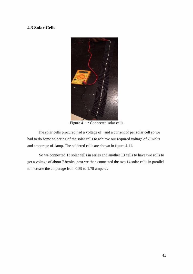
4.3 Solar Cells
Figure 4.11: Connected solar cells
The solar cells procured had a voltage of and a current of per solar cell so we
had to do some soldering of the solar cells to achieve our required voltage of 7.5volts
and amperage of 1amp. The soldered cells are shown in figure 4.11.
So we connected 13 solar cells in series and another 13 cells to have two rolls to
get a voltage of about 7.8volts, next we then connected the two 14 solar cells in parallel
to increase the amperage from 0.89 to 1.78 amperes

42
4.4 Assembly of the Solar UAV
Figure 4.12: Assembly tree
Figure 4.12 shows the assembly tree. After the structural part was manufactured,
the next step was the installation of all the electronical parts in the unmanned aerial
vehicle.
The motor was the first electronic component to be installed, it was mounted in
the front of the fuselage as shown in figure 4.13. First the motor mount was glued and
then the motor was screwed to the motor mount, next the propellers were fixed to the
motor while the motor wires was passed into the fuselage
Figure 4.13: Mounting of motor

43
The next electrical component installed was the ESC (electronic speed controller),
it had a different head from that of the motor so we cut the different heads and connected
the wires together. The ESC was also connected to the receiver and to the battery, while
the receiver was connected to the transmitter. After all the connection the receiver, ESC
and battery were all fitted into the fuselage as shown in figure 4.14.
Figure 4.14: Installation of electrical components in fuselage
The servos were the next electrical components installed on the wings and the
fuselage, for the wings two servos were mounted close to the ailerons and was connected
to the ailerons using short push rods. While two more servos were installed in the fuselage
what connected to the elevator and rudder by long push rods, all the servos were then
connected to the receiver which enables us control then with the use of the transmitter
The next installation done was connecting the solar cell, the solar cells were
connected in parallel and series to achieve the required output for the battery. The solar
cell were placed on the top of the wing using glue to hold them at some points to prevent
them from falling, the solar cell were then connected to the batteries using a voltage step
down to prevent the battery from blowing up.
Finally all the parts were jointed together using glue in some necessary places such
as connecting the wing to the fuselage, before the gluing of the various components the
parts were all wrapped with thin plastic sheets to ensure smoothness of the surface an also
make the aircraft look good.

44
4.5 Testing
4.5.1 Electrical Components Testing
The electrical parts were tested outside the unmanned aerial vehicle. The first part
tested was the motor, after connecting it to the ESC and the ESC to the receiver the motor
was mounted on balsa wood to test if the was working properly. Figure 4.15 shows the
connection and the motor rotating.
Figure 4.15: Motor testing
The servos where tested when they were all connected to the ailerons, rudder
and elevator using the transmitter. They were connected to different channels of the
receiver to check for oscillatory movement. The installed servos are shown in figure 4.16
Figure 4.16: Servos to ailerons
Another component tested was the solar cells, after the connection a voltmeter
was used to check the output voltage of the solar cells connected in series and then the

45
amperage when connected in parallel. Figure 4.17 shows the solar panel produced and
used to charge the battery.
Figure 4.17: Solar cells in series and parallel
Finally after all the parts were ready, a flight test was done for the solar unmanned
aerial vehicle.
Figure 4.18: Solar unmanned vehicle

46
4.5.2 Flight Test for First Model
After the assembly of the various components of the first model, the flight test was
carried out on the 15th of June 2016. The flight test was unsuccessful because of some
reasons
One of the many problems we faced was that the aircraft was not statically stable.
After inserting the batteries into the electronic box. The UAV became nose heavy which
caused it to crash immediately after launching into the air, so we inserted the battery into
the system and performed a balancing test which was placing the center of gravity of the
UAV on a pointed surface. Another was that the servos and ESC where all placed into
different channel on the receivers cause the control of the different component very
difficult.
Also the mode of launch was also wrong due to inexperience with UAVs, we hand
launched the UAV into the air without regarding the angle of attack on the wing structure,
which causes the plane to immediately stall after takeoff. After all the trial on the first
model as a result of the impacts it received when crashing the fuselage was destroyed and
a second model was made to correct the flight mistakes from the first model.
Figure 4.19: Flight take-off
Figure 4.20: Failed take-off
47
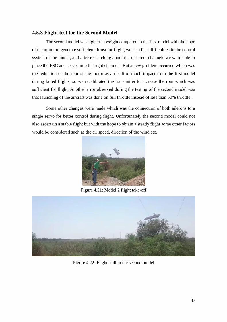
4.5.3 Flight test for the Second Model
The second model was lighter in weight compared to the first model with the hope
of the motor to generate sufficient thrust for flight, we also face difficulties in the control
system of the model, and after researching about the different channels we were able to
place the ESC and servos into the right channels. But a new problem occurred which was
the reduction of the rpm of the motor as a result of much impact from the first model
during failed flights, so we recalibrated the transmitter to increase the rpm which was
sufficient for flight. Another error observed during the testing of the second model was
that launching of the aircraft was done on full throttle instead of less than 50% throttle.
Some other changes were made which was the connection of both ailerons to a
single servo for better control during flight. Unfortunately the second model could not
also ascertain a stable flight but with the hope to obtain a steady flight some other factors
would be considered such as the air speed, direction of the wind etc.
Figure 4.21: Model 2 flight take-off
Figure 4.22: Flight stall in the second model

48
CHAPTER 5
Discussion and Result
Table 5.1 shows the results we obtained using the Matlab code from Andre north.
The value differed a bit from the actual values obtained during the manufacturing process
Table 5.1: Results from Matlab for estimate mass

49
The manufacturing of the Solarine was simple and it was made of widely available
material which is balsa wood. It gave a good strength and was easy to shape, but it needed
a little care of handling as its brittle when in sheets. The biggest problem faced in the
project was the brittleness of the solar cells. It was intended to use flexible solar cells
which are more efficient but it was costly. A more advanced transmitter and receiver was
needed to know more information about the situation of the battery.
During the flight test we observed that the stability of the models where greatly
affected by the battery in the UAV. Also we took note that to attain more stability in flight
the ailerons should be connected to a single servo, because of our inexperience with the
use of the transmitter in controlling the UAV.

50
CHAPTER 6
Conclusion
This report has discussed solar UAV's and the design and manufacturing
methodology. This report has shown the different classification and types of UAV's with
a history timeline of already made UAV's. The design and the methodology used was the
most important challenge in this project. A high wing configuration was used as it is
easier, it enhances stability and it gives some room for error for beginners. A V-tail
configuration was used for its simplicity but was changed to a conventional tail because
of stability problems in the unmanned vehicle. For the mass and power estimation of the
RC plane various equations were used from A. Noth's design of solar powered airplane
for continuous design. At the end there was the material selection where the most suitable
and cost efficient motor, propeller, ESC and material used to make the airframe were
selected. We think that our design is really suitable for a cost efficient solar powered UAV
as it is simple to manufacture.

51
APPENDIX A
David Dangana 127342
11/10/2015
Meeting with the supervisor to talk about the selected capstone
project
13/10/2015
Meeting with group members to gadder information about capstone
project
13/11/2015
Preparing Chapter 1, the introduction of the project
18/11/2015
Meeting with supervisor to discuss the introduction and literature
review
18/11/2015
Meeting with group members to select a design and name for the
project
20/11/2015
Choosing and Airfoil for the wing configuration and selecting the
length of the wing chord to calculate the dimensions for the wing,
25/11/2015
Performing the wing analysis on XFLR with group members
2/11/2015
Selecting the required formulas to calculate the mass and power
estimate of the aircraft
7/12/2015
Meeting with supervisor to show our progress on the project
11/12/2015
Selecting the tail configuration and Airfoil and calculating the
required dimensions. Also performing the tail analysis on XFLR
software with group members

52
12/12/2015
Running MATLAB code from Andre Noth. And later inputting our
initial parameters to obtain the mass and power estimates
13/12/2015
Designing of the wing, tail and fuselage on solidworks
15/12/2015
Meeting with supervisor to show progress and get more information
about the project
15/12/2015
Selection of materials needed and preparation of bill of materials
for the project with group members
15/12/2015
Preparing chapter 3 with all information obtained
1/1/2016 Meeting with group members to discuss manufacturing process
8/2/2016 Manufacturing of ribs and spar
15/3/2016 Assembly of wing
15/5/2016 Installation of servos and push rods
Mazen Abdulrazik 125534

53
5/10/2015
Choosing the project desired with the group
11/10/2015
Meeting with the supervisor to understand the requirements of the project
13/10/2015
Gathering information about solar energy and UAVs
15/10/2015
Writing the Solar Energy part in Chapter 1
18/10/2015
Meeting with the Supervisor to know our next step
18/10/2015-
25/10/2015
Gathering information about different types of UAVs and their classification
26/10/2015-
1/11/2015
Meeting with my group member on daily basis to finish Literature review chapter
2/11/2015
Meeting with group members to select a design and name for the project
5/11/2015
Performing the wing analysis on XFLR with group members
9/11/2015
Meeting with supervisor to show our progress on the project
11/11/2015
Performing the tail analysis on XFLR software with group members
13/11/2015-
20/11/2015
CAD/CAM drawings
21/11/2015
30/11/2015
Selecting and ordering electrical components according to the results obtained
from MATLAB
5/12/2015
Selecting the solar cells to be used and contacting the manufacturer
7/12/2015
Meeting with the supervisor to check our progress

54
7/12/2015
15/12/2015
Meeting with the group member to start writing chapter 3
1/1/2016 Meeting with group members to discuss manufacturing process
8/1/2016 Working on the wing group members in the workshop
15/1/2016 Working on the fuselage with group members in the workshop
23/1/2016 Working on the tail with group members in the workshop

55
Yehia Jamaoui 138037
5/10/2015
Choosing the desired project with the group
11/10/2015
Meeting with the supervisor to discuss the selected capstone project
13/10/2015
Gathering information about solar energy and UAVs
15/10/2015
Preparing chapter 1, the introduction
18/10/2015
Meeting with the group to assign weights
18/10/2015-
25/10/2015
Gathering information about different types of UAVs and their classification
26/10/2015-
1/11/2015
Meeting with my group member on daily basis to finish Literature review chapter
2/11/2015
Meeting with the supervisor to discuss the next step
5/11/2015
Performing the wing analysis on XFLR with group members
11/11/2015
Performing the tail analysis on XFLR software with group members
13/11/2015-
20/11/2015
CAD/CAM drawings
21/11/2015
30/11/2015
Selecting and ordering electrical components according to the results obtained
from MATLAB
5/12/2015
Selecting the solar cells to be used and contacting the manufacturer
7/12/2015
Meeting with the supervisor to show our progress on the project

56
7/12/2015
15/12/2015
Discussing the project’s progress among the group and putting plan for the next
step
3/1/2016 Meeting with group members to discuss manufacturing process
8/1/2016 Working on the wing group members in the workshop
15/1/2016 Working on the fuselage with group members in the workshop
23/1/2016 Working on the tail with group members in the workshop

57
APPENDIX B

58
APPENDIX C
59
60

61

62

63
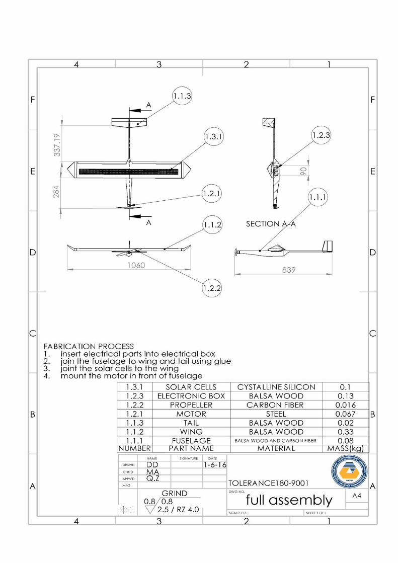
Figure C-1: Full assembled model
Figure C-2: Individual parts for assembly

64
APPENDIX D
Table D-1: Comparing the Solarine with other solar UAVs
Figure D-1 Specifications of Cyanoacrylate Glue
Table D-2: Results from Matlab for estimate mass and Power
Solar Solitude Solar Excel Sun Sailor 1/2 The Solarine
Weight (kg) 2 0.72 3.6 0.723
Range (km) 38.84 48.31 139 10
Endurance (hrs) - 11.5 - 1
Aspect ratio 13.3 12.8 13.15 6
Wing span (m) 2.7 2.1 4.2 0.9
Wing area
(m^2)
0.55 0.35 1.35 0.135
Altitude (m) 1283 2065 200 400
Mass 0.2145kg
Total Electric Power 13.3W
Power for Level Flight 1.097W
Max. Solar Electric Power 4.6432W
Level flight speed 5.69m/s
Total Drag 0.1926
Wing surface Area 0.1350m2
65
APPENDIX E All information about the electrical parts a were obtained from hobbyking.com
Electrical Components Selection and specification
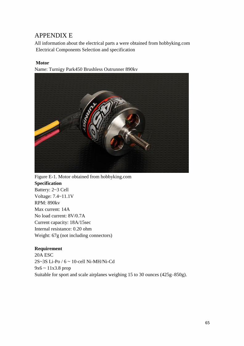
Motor
Name: Turnigy Park450 Brushless Outrunner 890kv
Figure E-1. Motor obtained from hobbyking.com
Specification
Battery: 2~3 Cell
Voltage: 7.4~11.1V
RPM: 890kv
Max current: 14A
No load current: 8V/0.7A
Current capacity: 18A/15sec
Internal resistance: 0.20 ohm
Weight: 67g (not including connectors)
Requirement
20A ESC
2S~3S Li-Po / 6 ~ 10-cell Ni-MH/Ni-Cd
9x6 ~ 11x3.8 prop
Suitable for sport and scale airplanes weighing 15 to 30 ounces (425g–850g).
66
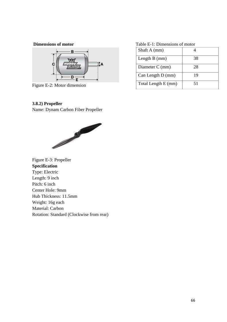
Dimensions of motor Table E-1: Dimensions of motor
Figure E-2: Motor dimension
3.8.2) Propeller
Name: Dynam Carbon Fiber Propeller
Figure E-3: Propeller
Specification
Type: Electric
Length: 9 inch
Pitch: 6 inch
Center Hole: 9mm
Hub Thickness: 11.5mm
Weight: 16g each
Material: Carbon
Rotation: Standard (Clockwise from rear)
Shaft A (mm) 4
Length B (mm) 38
Diameter C (mm) 28
Can Length D (mm) 19
Total Length E (mm) 51

67
Batteries
Name: Turnigy nano-tech
Figure E-4: Battery
Specification
Capacity: 1000mAh
Voltage: 2S1P / 2 Cell / 7.4V
Discharge: 25C Constant / 50C Burst
Weight: 60g (including wire, plug & case)
Dimensions: 71x35x12mm
Balance Plug: JST-XH
Discharge Plug: XT60
Battery Dimension Table E-2: Battery dimension
Figure E-5: Battery Dimension
Electronic speed controllers
Name: Turnigy Multistar 20A V2 Slim BLHeli Multi-Rotor Brushless ESC 2-6S
Figure E-6: Electronic speed controllers
Specifications
Constant Current: 20A
Input Voltage: 2-6 cell Lipoly
Length-A(mm) 71
Height-B(mm) 35
Width-C(mm) 12

68
BEC: Yes (linear) [Remove middle wire to disable]
BEC Output: 5V/3A
PWM: 8 KHz
Max RPM: 240,000rpm for 2 Pole Brushless Motor
PCB Size: 62mm x 13mm
Discharge Plugs: Male 3mm Bullet Connector
Motor Plugs: Female 3mm Bullet Connector
Weight: 20.3g
A cable is required to connect the ESC to the batter since the have different connection
types which are bullet and XT60
Servos
Two servos are selected one for the aileron and the other for the ruddervator
Servo 1 is for ruddervator and servo 2 for aileron
Figure E-7: Servo 1 dimension
Table E-3: Servo 1 dimension
Table E-4: Specification of servo 1
A(mm) 33
B(mm) 36
C(mm) 30
D(mm) 15
E(mm) 50
F(mm) 20
Weight (g) 8.4
Torque (kg) 1.5
Speed (Sec/60deg) 0.12

69
Servo 2
Figure E-8: Servo 2 dimension
Table E-5: Servo 2 dimension
Table E-6: specification of servo 2
A(mm) 30
B(mm) 25
C(mm) 26
D(mm) 12
E(mm) 34
F(mm) 15
Weight (g) 25
Torque (kg) 2.3
Speed (Sec/60deg) 0.08
70
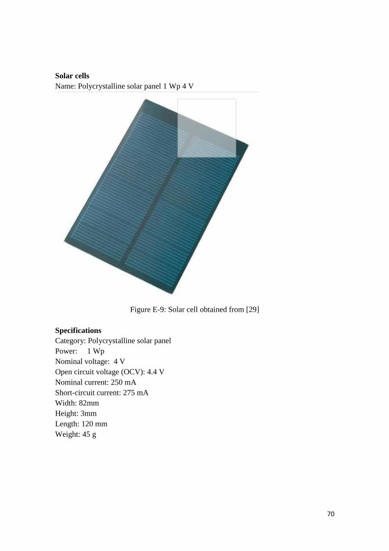
Solar cells
Name: Polycrystalline solar panel 1 Wp 4 V
Figure E-9: Solar cell obtained from [29]
Specifications
Category: Polycrystalline solar panel
Power: 1 Wp
Nominal voltage: 4 V
Open circuit voltage (OCV): 4.4 V
Nominal current: 250 mA
Short-circuit current: 275 mA
Width: 82mm
Height: 3mm
Length: 120 mm
Weight: 45 g

71
Bill of materials
*excluding payment for shipping of various parts from www.hobbyking.com and
www.conrad.com/ce

72
DESIGN specifications
Wing chord (cm) = 15 Tail Aperture (α) = 26
Wingspan (cm) = 90 Tail span (cm) = 30
Wing Area (cm2) = 1350 Ruddervator Chord (cm) = 3.2
Fuselage (cm) = 67.5 Total Ruddervator Surface Area (cm2) = 96
Aileron (cm) = 1.9 Tail area (cm2) = 270
Aspect ratio = 6 Ruddervator Length (cm) = 30

73
Matlab code by Andre North
%========================================================================== %=== Global Design of Relay UAV %=== - Initialization of Parameters - %=== May, 2010 %=== %=== This code initialize parameters for the design program of Relay UAV %=== (or other solar airplane in general) %==========================================================================
%AR = 6; % Aspect Ratio g=9.81; % Gravitational acceleration [m/s^2] alt=200; % Initial altitude [m] alt_array=[0, 1000, 2000, 4000, 6000, 10000, 15000, 20000 ]; rho_array=[1.224, 1.11, 1.006, 0.819, 0.659, 0.413, 0.192, 0.087, 0.039,
0.017]; rho=spline(alt_array,rho_array,200); % Airdensity at 500m [kg/m^3]
%=========== Irradiance conditions ============== I_max=900; % Maximum irradiance [W/m^2] T_day=13.2*3600; % Duration of the day [s] n_wthr=0.7; % Margin factor <1 take clouds into account [-]
%================ Aerodynamics ================== C_L=0.8; % Airfoil lift coefficient [-] C_D_afl=0.04; % Airfoil drag coefficient [-] C_D_par=0.007; % Fuselage drag coefficient [-] e=0.9; % Constant depending on wing shape [-]
%======= Wing & fuselage Structure ============== k_af=0.75/9.81; % Constant [~Kg/m3] x1=3.1; % Scaling exponent for b [-] x2=-0.25; % Scaling exponent for AR [-]
%============= Propulsion group ================= n_ctrl=0.95; % Efficiency of motor controller [-] n_mot=0.85; % Efficiency of motor [-] n_grb=0.97; % Efficiency of gearbox [-] n_plr=0.60; % Efficiency of propeller [-] k_prop=0.008; % Mass/Power ration of propulsion group [kg/W]
%======= Battery and Stepdown converter ========= n_chrg=0.95; % Efficiency of charge process [-] n_dschrg=0.95; % Efficiency of discharge process [-] n_bec=0.65; % Efficiency of bec (5V stepdown) [-] k_bat=190*3600; % Energy density of LiPo [J/Kg]
%================ Solar cells =================== k_sc=0.32; % Mass density of solar cells [Kg/m2] k_enc=0.26; % Mass density of encapsulation [Kg/m2] k_mppt=1/2386; % Mass/Power ratio of mppt [kg/W] n_sc=0.169; % Efficiency of solar cells [-] n_cbr=0.9; % Efficiency of cambered configuration [-] n_mppt=0.97; % Efficiency of mppt [-]
%============== Avionics & Payload ============== m_av=0.15; % Mass of controler and electronics [kg]

74
m_pld=0.05; % Mass of payload [kg] p_av=1.5; % Power required for control [W] p_pld=0.6; % Power required for payload [W]
%============== End of File =====================

75
%========================================================================== %=== Global Design of Sky-Sailor Airplane %=== - Evaluation of the solution - %=== May 2010 %=== %=== This code evaluates, based on given parameters, the feasibility of a %=== certain configuration of solar airplane. In one sentence, the main %=== problem is to balance weight/lift and obtained/required power. %========================================================================== C_D_ind = C_L^2/(e*pi*AR); % Induced drag coefficient [-] C_D=C_D_afl+C_D_ind+C_D_par; % Total drag coefficient [-]
C_D_afl= Airfoil drag coefficient
a0=C_D/(C_L^1.5)*sqrt(2*AR*(g^3)/rho); % Eq 3.5 a1=1/(n_ctrl*n_mot*n_grb*n_plr); % Eq 3.6 a2=1/(n_bec)*(p_av+p_pld); % Eq 3.6 a3=m_av+m_pld; % Eq 3.10 a4=k_af*AR^x2; % Eq 3.25 a5=k_sc+k_enc; % Eq 3.27 a6=k_mppt*I_max*n_sc*n_cbr*n_mppt; % Eq 3.28 a7=T_night/(n_dschrg*k_bat); % Eq 3.30 a8=k_prop; % Eq 3.32 a9=pi/(2*n_sc*n_cbr*n_mppt*n_wthr)*... % Eq 3.26 (1+T_night/(T_day*n_chrg*n_dschrg))*1/I_max; a10=a0*a1*(a7+a8+a9*(a5+a6)); % Eq 3.34 a11=a2*(a7+a9*(a5+a6))+a3; % Eq 3.34 a12=a10*1/b; % Eq 3.35 a13=a11+a4*b^x1; % Eq 3.35
z=roots([a12 -1: 0 a13]); % Solving equation to find
mass Sol_m = min(z)^2; % It can be 2 masses, we take
the smallest one
if (isnan(Sol_m)==0) % If a solution is found, we compute
... Sol_P_level = a0*Sol_m^1.5/b; % Eq 3.5 level flight power Sol_m_af = a4*b^x1; % Eq 3.25 airframe mass Sol_P_elec_tot = a1*Sol_P_level+a2; % Eq 3.6 total electric power (level
flight) Sol_m_bat = a7*Sol_P_elec_tot; % Eq 3.30 battery mass Sol_A_sc=a9*Sol_P_elec_tot; % Eq 3.26 solar panels area Sol_m_sc = a5*Sol_A_sc; % Eq 3.27 solar panels mass Sol_m_mppt = a6*Sol_A_sc; % Eq 3.28 mppt mass Sol_P_sc = a6*Sol_A_sc/k_mppt; % Eq 3.28 solar electrical power max Sol_m_prop = a8*a1*Sol_P_level; % Eq 3.32 propulsion group mass Sol_v = sqrt(2*Sol_m*g/(C_L*rho*b*b/AR)); % Eq 3.3 level flight speed Sol_D = Sol_m*g/C_L*C_D; % Eq 3.1-2 total drag Sol_A = b^2/AR; % wing surface end
if ((isnan(Sol_m)==1 || (Sol_A_sc > b*b/AR))) % If no solution, Nan is
returned
Sol_P_level = NaN; Sol_m_af= NaN; Sol_P_elec_tot= NaN; Sol_m_bat= NaN; Sol_A_sc= NaN; Sol_m_sc= NaN; Sol_m_mppt= NaN;

76
Sol_P_sc= NaN; Sol_m_prop= NaN; Sol_v= NaN; Sol_D= NaN; Sol_A= NaN; end
%=========================End of File===========================%

77
%========================================================================== %=== Global Design of Sky-Sailor Airplane %=== - Plot Example for Unmanned Aerial Vehicle - %=== May 2010 %=== %=== This code tries different combinations of wingspan and aspect ratio %=== and then evaluates the feasibility or not of the solution. It uses the %=== technological & mission parameters from Initparameters. The results %=== are plotted on graph where one can also see the mass distribution. %========================================================================== clc;clear;clf; cmap=colormap(gray(100)); j=0;
InitParameters; % Parameters are initialized T_night=24*3600-T_day; % Duration of the night [s]
for AR = [1,2,3,4,5,6,7,8,9,10] % For different aspect ratios... j=j+1; col=cmap(floor(((100-10)-0)/(10-1)*(AR-1))+1,:);
%=============================================== %=== CALCULATION ==== %===============================================
i=0; b_max=3; b_step=0.1;
for b=b_step:b_step:b_max % And different wingspans... EvaluateSolution; % ... the solution feasibiliy is computed i=i+1; m(i)=Sol_m; P_level(i)=Sol_P_level; m_af(i)=Sol_m_af; P_elect_tot(i)=Sol_P_elec_tot; m_bat(i)=Sol_m_bat; A_sc(i)=Sol_A_sc; m_sc(i)=Sol_m_sc; m_mppt(i)=Sol_m_mppt; P_sc(i)=Sol_P_sc; m_prop(i)=Sol_m_prop; v(i)=Sol_v; D(i)=Sol_D; A(i)=Sol_A; end
%=============================================== %=== PLOTS === %===============================================
width=2; b=b_step:b_step:b_max;
figure(1);
set(gcf,'Position',[1056 204 560 420]); hold on; plot(b,m,'Color',col,'LineWidth',width); % Plot total mass wrt to AR and
b [m_min.m(j),index]=min(m); m_min.b(j)=b(index); grid on; xlabel('Wingspan [m]'); ylabel('Total Mass of Solar Airplane [Kg]');
figure(2);

78
set(gcf,'Position',[487 704 800 420]);
subplot (2,2,1);
hold on; plot(b,v,'Color',col,'LineWidth',width); % Plot speed wrt to AR and b [v_min.v(j),index]=min(v); v_min.b(j)=b(index); grid on; ylabel('Speed [m/s]')
subplot(2,2,3);
hold on; plot(b,P_level,'Color',col,'LineWidth',width) % Plot the propeller power wrt
to AR and b grid on; ylabel('Power at propeller [W]'); xlabel('Wingspan [m]');
subplot(2,2,2);
hold on; plot(b,A,'Color',col,'LineWidth',width); % Plot wing area wrt to AR and b grid on; ylabel('Wing Area [m^2]'); Subplot(2,2,4); hold on;
plot(b,A_sc./A*100,'Color',col,'LineWidth',width); % Plot solar area wrt to AR
and b
[ratio_area_min.ratio_area(j), index]=min(A_sc./(b.^2/AR)*100); ratio_area_min.b(j)=b(index); grid on; xlabel('Wingspan [m]'); ylabel('Solar Area Ratio [%]');
if (AR == 13) figure(3);set(gcf,'Position',[487 204 560 420]); area(b,[m./m*m_pld;m./m*m_av;m_af;m_bat;m_sc;m_mppt;m_prop]'); legend('Payload','Avionics','Airframe','Batteries','Solar Panels','Mppt',... 'Propulsion group','Location','NorthWest'); xlabel('Wingspan [m]'); ylabel('Mass [kg]'); colormap(gray(100)); end end figure(1);
plot(m_min.b,m_min.m,'xk','MarkerSize',4); legend('1','2','3','4','5','6','7','8','9','10','Location','NorthWest');
figure(2);
subplot(2,2,1); plot(v_min.b,v_min.v,'xk','MarkerSize',4); subplot(2,2,4); plot(ratio_area_min.b,ratio_area_min.ratio_area,'xk','MarkerSize', 4); legend('1','2','3','4','5','6','7','8','9','10','Location','NorthWest');

79
References
[1] James Bratley. (19 June 2013). Additional Information On Solar Energy. Retrieved
from http://www.clean-energy-ideas.com/energy/energy-dictionary/solar-energy-
definition on 8/11/2015
[2] Solar Energy. Retrieved from http://www.seia.org/about/solar-energy on 9/11/2015
[3] How Photovoltaic Cells Work. Retrieved from
http://solarenergy.net/solar-power-resources/how-photovoltaic-cells-work/on
10/11/2015
[4] Definition of UAV. Retrieved from http://www.theUAV.com/ on 9/11/2015
[5] Tom Scheve. How the MQ-9 Reaper Works Retrieved from
http://science.howstuffworks.com/reaper1.htm/ on 11/11/2015
[6] Time Line of UAVs. Retrieved from
http://www.pbs.org/wgbh/nova/spiesfly/UAVs.html 9/11/2015
[7] Maria De Fatima Bento. Unmanned Aerial Vehicle An Overview Retrieved on
9/11/2015
[8] D. Alemayehu, E. Eaton, I. Faruque. HALE: Aerovironment Pathfinder
[9] Thomas E. Noll. Investigation of helios prototype Aircraft mishap. NASA Langley
Research Center
[10] Wing configuration. Retrieved from
http://2bfly.com/knowledgebase/airplanes/wing-configuration/ on 29/11/2015
[11] Rohan S. Sharma. (2014). Symposium on Undergraduate Research & Creative
Expression:
Light aircraft solar extended rang. America Iowa State University of Science and
Technology.
[12] André Noth. (2008). Design of Solar Powered Airplanes for Continuous Flight.
Switzerland ETH Zürich.

80
[13] Niels Diepeveen. (2007). The Sun-Surfer: Design and construction of a solar powered
MAV.
Switzerland ETH Zurich.
[14] D.P. Raymer. (1992). Aircraft Design: A Conceptual Approach. (2nd Ed). America
Ohio.
AIAA Education Series
[15] J. Roskam. (1985-1990).Airplane Design Part I-VIII. Kansas, University of
Lawrence Kansas
[16] Christopher J. Hartney. (2011). Design of a small solar-powered unmanned aerial
vehicle.
California, San José State University
[17] Motor Selection Guide. (2012). Retrieved from http://rcmentor.com/helloworld/ on
20/11/2015
[18] Prof. A Mehta. A, Joshi. C, Solanki. K, Yadav. S. (2013). Design and Fabrication of
Solar
R/C. Model Aircraft. International Journal of Modern Engineering Research
(IJMER). 3(2),
752-758
[19] Understanding rc servos digital, analog coreless, brushless. Retrieved from
http://www.rchelicopterfun.com/rc-servos.html on 30/11/2015
[20] RC transmitter modes for airplanes. Retrieved from
http://www.rc-airplane-world.com/rc-transmitter-modes.html on 12/10/2015
[21] Black Widdow Micro UAV (2014) Retrieved from http://defense-
update.com/20040604_black-widdow.html Retrieved on 23/12/2015 on 23/12/2015
[22] Milestones Retrieved from http://baykarmakina.com/about-us/milestones/?lang=en
on 23/12/2015
[23] NASA Pathfinder Retrieved from https://en.wikipedia.org/wiki/NASA_Pathfinder
on 23/12/2015

81
[24] Helios Retrieved from from https://www.avinc.com/uas/adc/helios/ on 23/12/2015
[25] Davut Solyalı. (2013). An investigation into integration of renewable energy source
for electricity generation A case study of Cyprus. England, University of Bath
[26] SolarGIS © 2011 GeoModel Solar s.r.o., Maps of Global horizontal irradiation (GHI)
of Cyprus, Available at: http://solargis.info/doc/_pics/freemaps/1000px/ghi/SolarGIS-
Solar-map-Cyprus-en.png Retrieved on 23/12/2015
[27] L. Hadjioannou, Three years of operation of the radiation center in Nicosia, Cyprus.
Meteorological Note Series No. 2, March 1987, Meteorological Service of South Cyprus
[28] Noth, A., Siegwart, R., (2006) Design of an Ultra-Lightweight Autonomous Solar
Airplane
for Continuous Flight, Aircraft & Spacecraft Systems Design Lecture Notes, Zurich,
Switzerland
[29] Solar cell retrieved from
http://www.conrad.com/ce/en/product/110455/Polycrystalline-solar-panel-1-Wp-4-
V?ref=list on 23/12/2015
[30] Electronic Speed Controller Basics retrieved from
http://www.hooked-on-rc-airplanes.com/Electronic-speed-controller.html on 27/12/2015
[31] UIUC Airfoil Coordinates Database. Retrieved from
http://m-selig.ae.illinois.edu/ads/coord_database.html on 27/12/2015
[32] Solar Energy. Retrieved from http://cockroach-boat.weebly.com/energy.html on
27/12/2015
[33] Motor parts. Retrieved from https://grabcad.com/ on 28/12/2015