MEMS-IC Common Platform MEMS+ · MEMS+IC Challenge System, IC and layout designers require a MEMS...
34
MEMS-IC Common Platform MEMS+ 2012
Transcript of MEMS-IC Common Platform MEMS+ · MEMS+IC Challenge System, IC and layout designers require a MEMS...

MEMS-IC Common Platform
MEMS+
2012
Slide 2
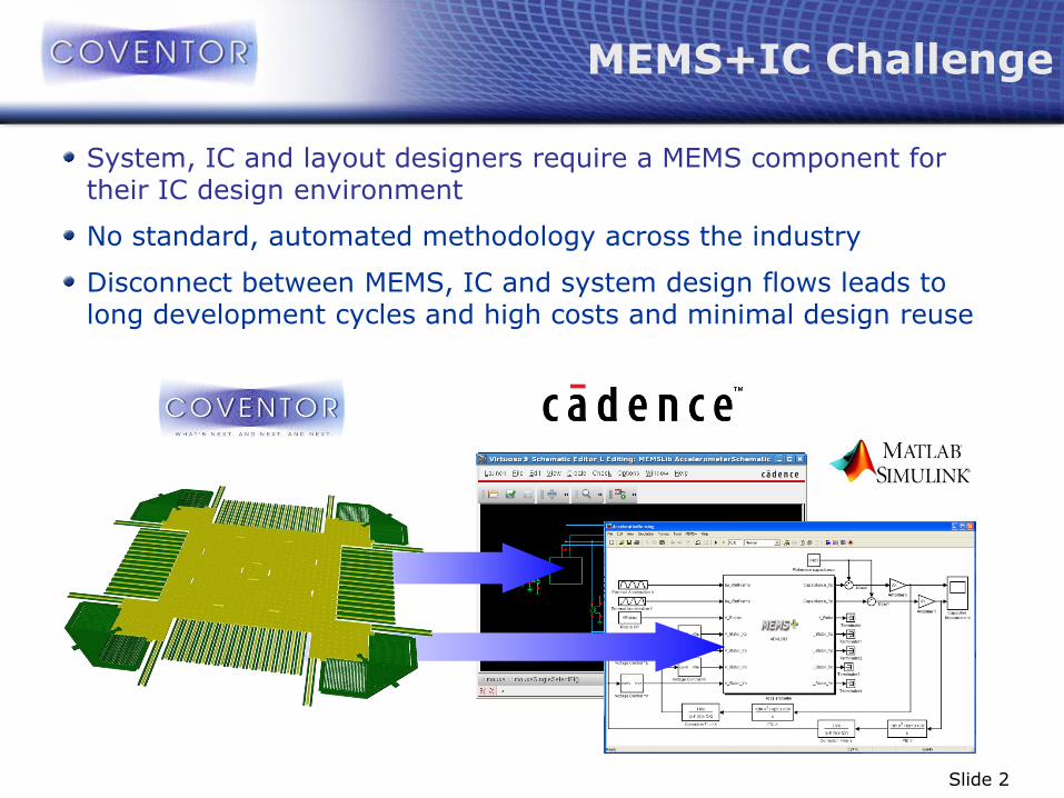
MEMS+IC Challenge
System, IC and layout designers require a MEMS component for their IC design environment
No standard, automated methodology across the industry
Disconnect between MEMS, IC and system design flows leads to long development cycles and high costs and minimal design reuse
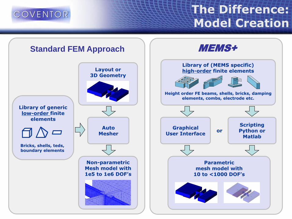
Standard FEM Approach MEMS+
Layout or 3D Geometry
Auto Mesher
Non-parametric Mesh model with 1e5 to 1e6 DOF’s
Library of generic low-order finite
elements
The Difference: Model Creation
Bricks, shells, teds, boundary elements
Library of (MEMS specific) high-order finite elements
Parametric mesh model with
10 to <1000 DOF’s
Graphical User Interface
Scripting Python or
Matlab
Height order FE beams, shells, bricks, damping elements, combs, electrode etc.
or
Slide 4
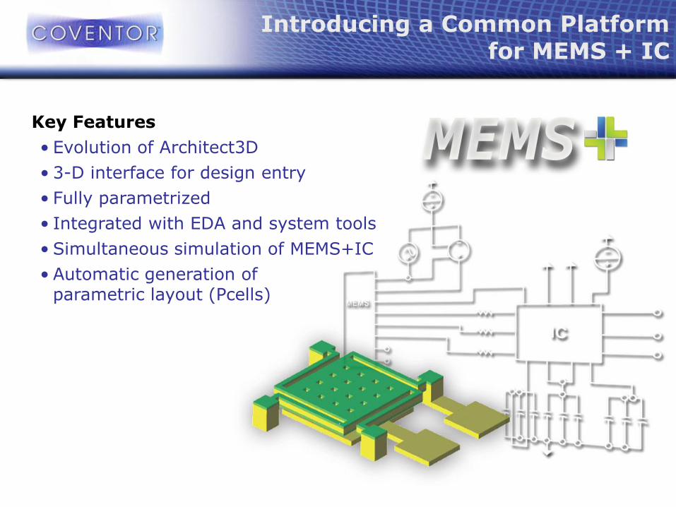
Introducing a Common Platform for MEMS + IC
Key Features
• Evolution of Architect3D
• 3-D interface for design entry
• Fully parametrized
• Integrated with EDA and system tools
• Simultaneous simulation of MEMS+IC
• Automatic generation of parametric layout (Pcells)
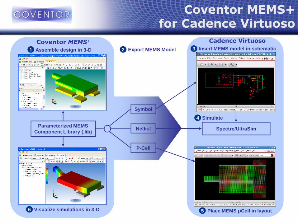
Parameterized MEMS
Component Library (.lib)
Coventor MEMS+
Assemble design in 3-D 1
Coventor MEMS+ for Cadence Virtuoso
Visualize simulations in 3-D 6
Export MEMS Model 2
P-Cell
Netlist
Symbol
Cadence Virtuoso
Insert MEMS model in schematic 3
Place MEMS pCell in layout 5
Spectre/UltraSim
Simulate 4
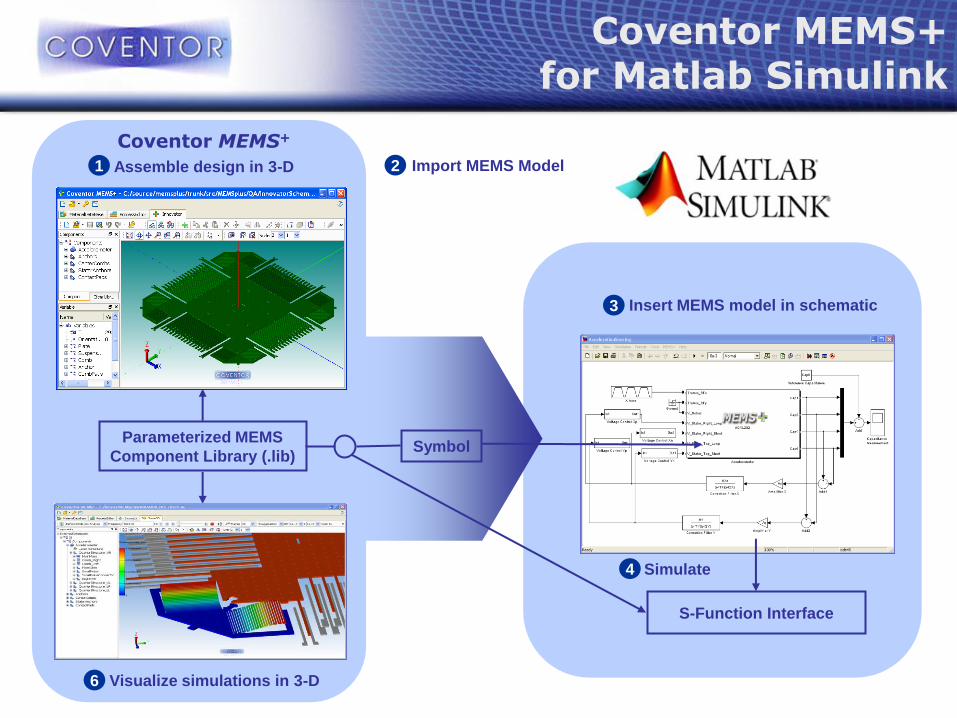
Parameterized MEMS
Component Library (.lib)
Coventor MEMS+
Assemble design in 3-D 1
Visualize simulations in 3-D 6
Coventor MEMS+ for Matlab Simulink
Insert MEMS model in schematic 3
Import MEMS Model 2
Symbol
S-Function Interface
Simulate 4
Slide 7
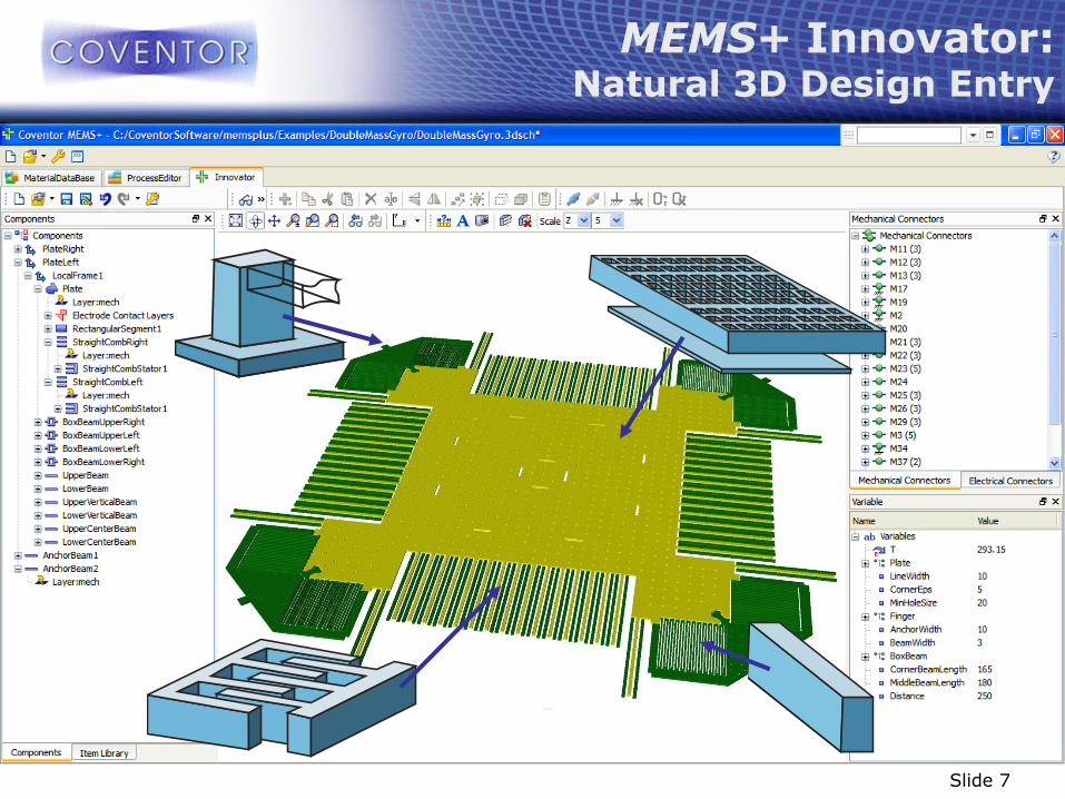
MEMS+ Innovator: Natural 3D Design Entry
Slide 8
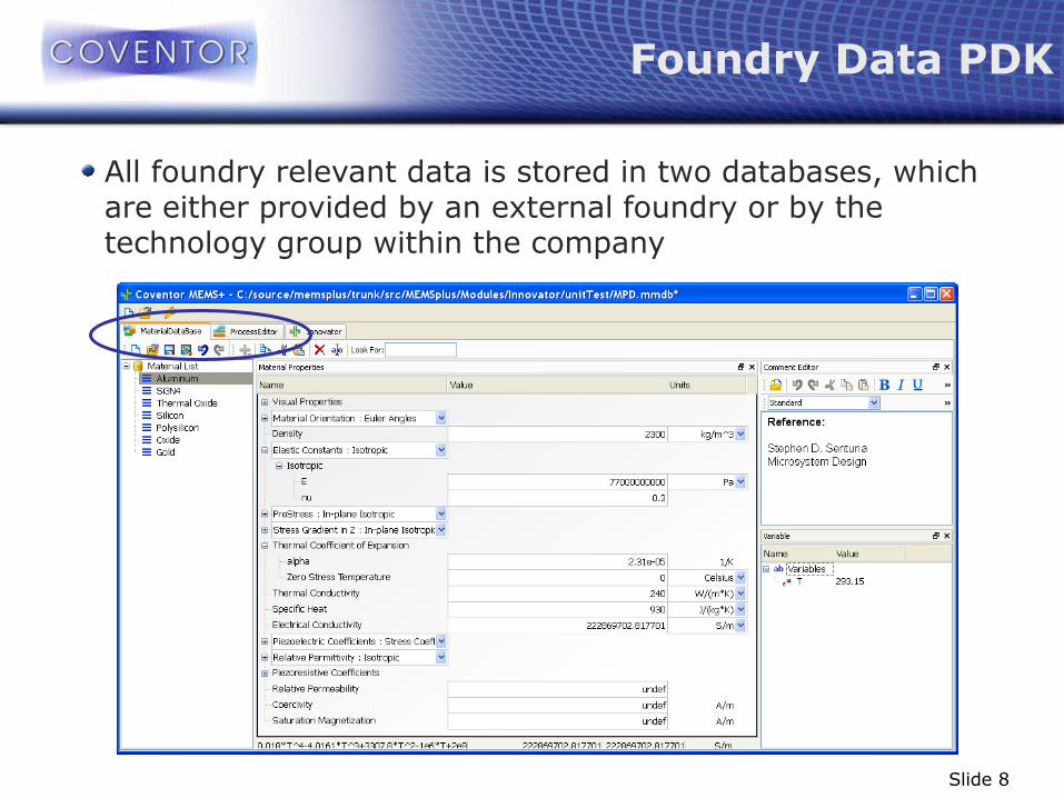
All foundry relevant data is stored in two databases, which are either provided by an external foundry or by the technology group within the company
Foundry Data PDK

Slide 9
Material properties can be defined as values, variables or algebraic equations
Variable Assignment
Slide 10
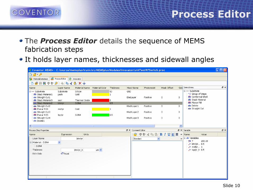
The Process Editor details the sequence of MEMS fabrication steps
It holds layer names, thicknesses and sidewall angles
Process Editor
Slide 11
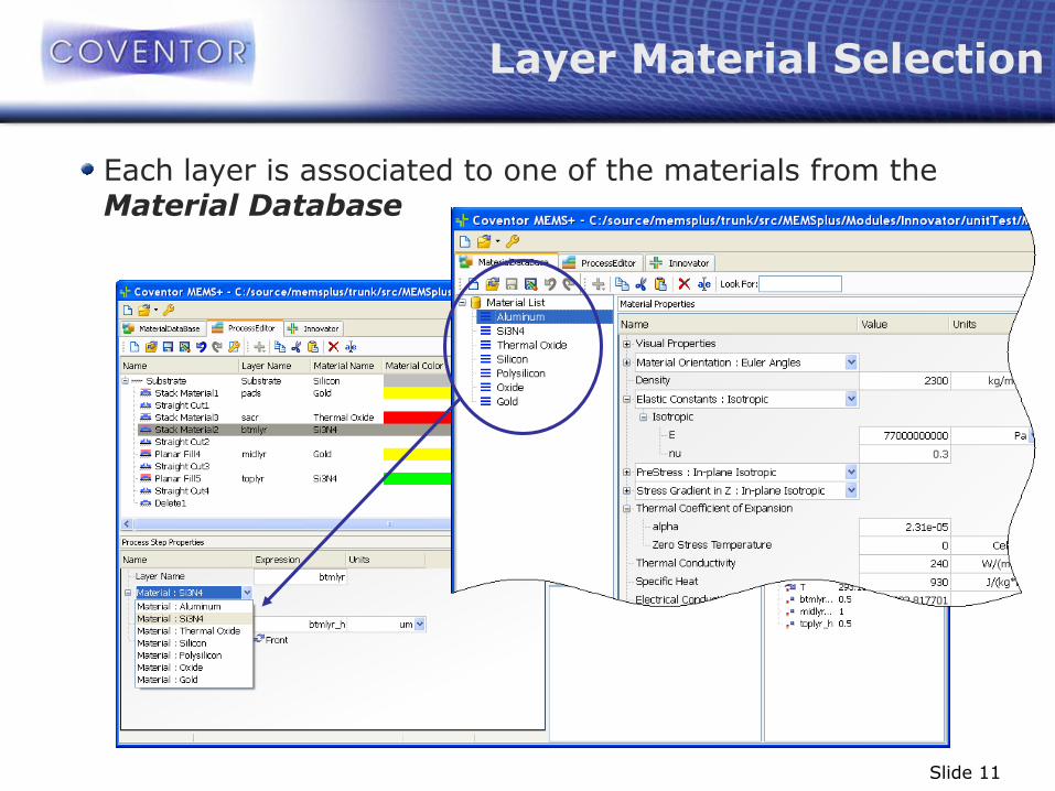
Each layer is associated to one of the materials from the Material Database
Layer Material Selection
Slide 12
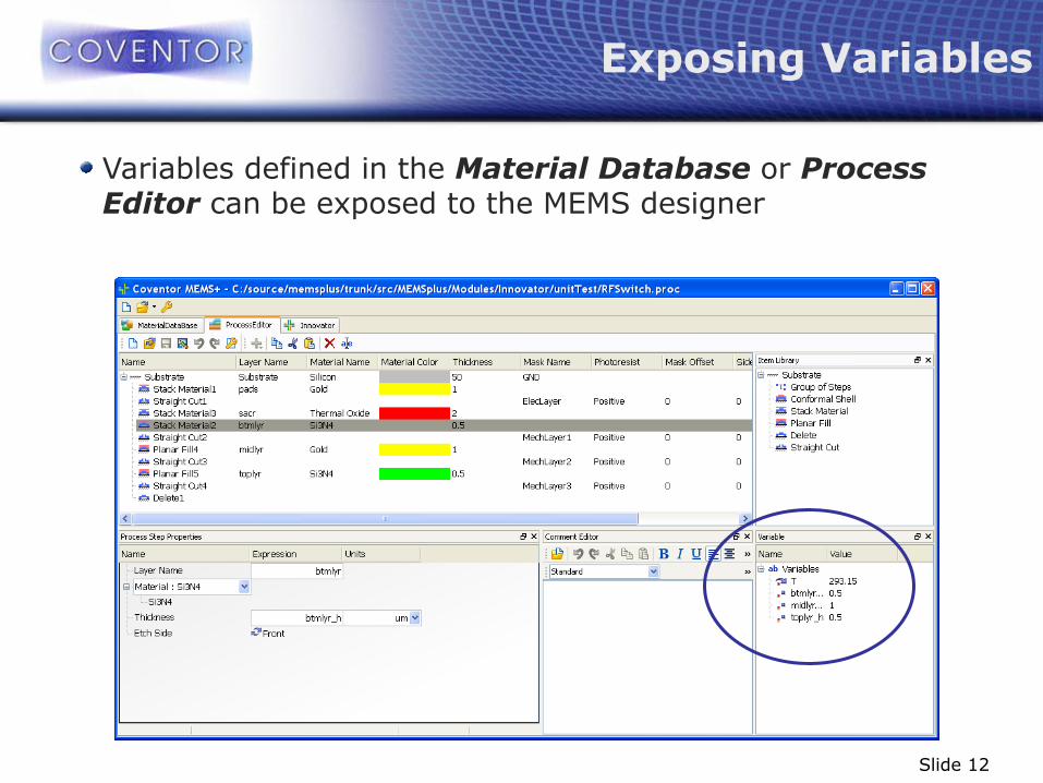
Variables defined in the Material Database or Process Editor can be exposed to the MEMS designer
Exposing Variables

Slide 13
Why Process Variables?
MEMS versus IC Design
Customized or semi-customized processes are common; e.g., MEMS designer might be able to change a structural layer thickness within limits
MEMS component models like suspensions, combs and electrodes are not foundry specific
Varying process and material data are key for PDK development and yield analysis

Slide 14
The MEMS designer starts with a blank, 3-D canvas on the Innovator tab
Innovator
Slide 15
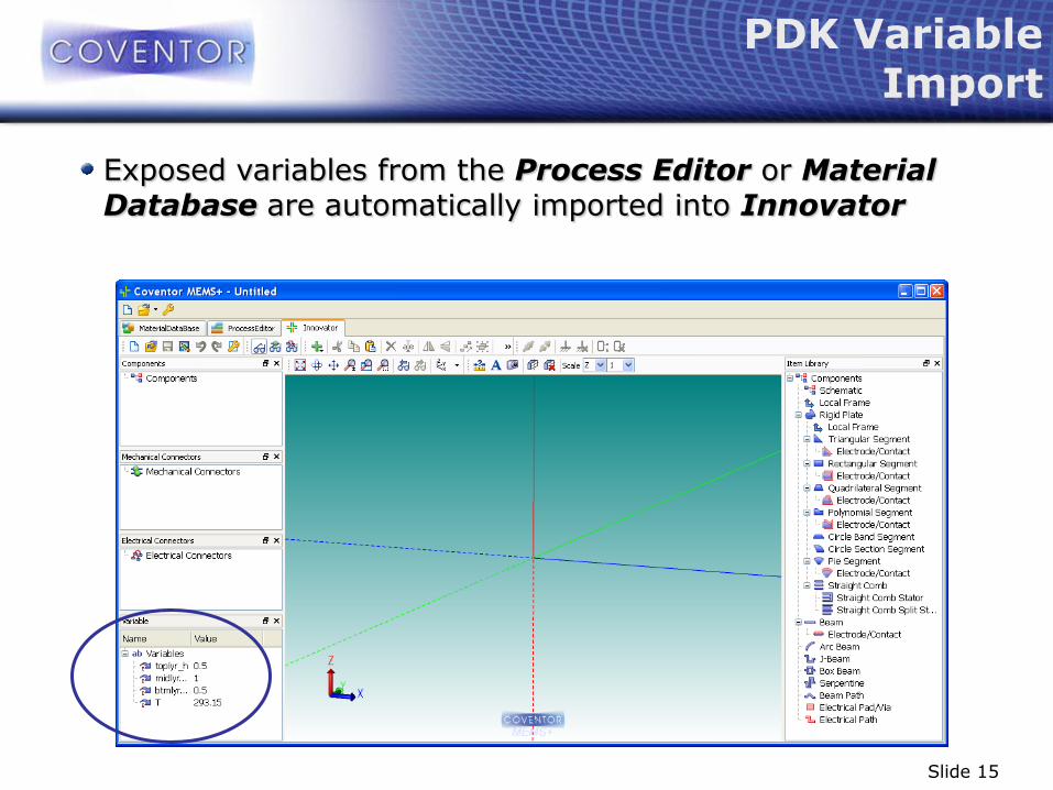
Exposed variables from the Process Editor or Material Database are automatically imported into Innovator
PDK Variable Import

Slide 16
MEMS device models are created with a library of parametric component generators for suspensions, plates, combs and electrical pads
Parametric Component Library
Slide 17
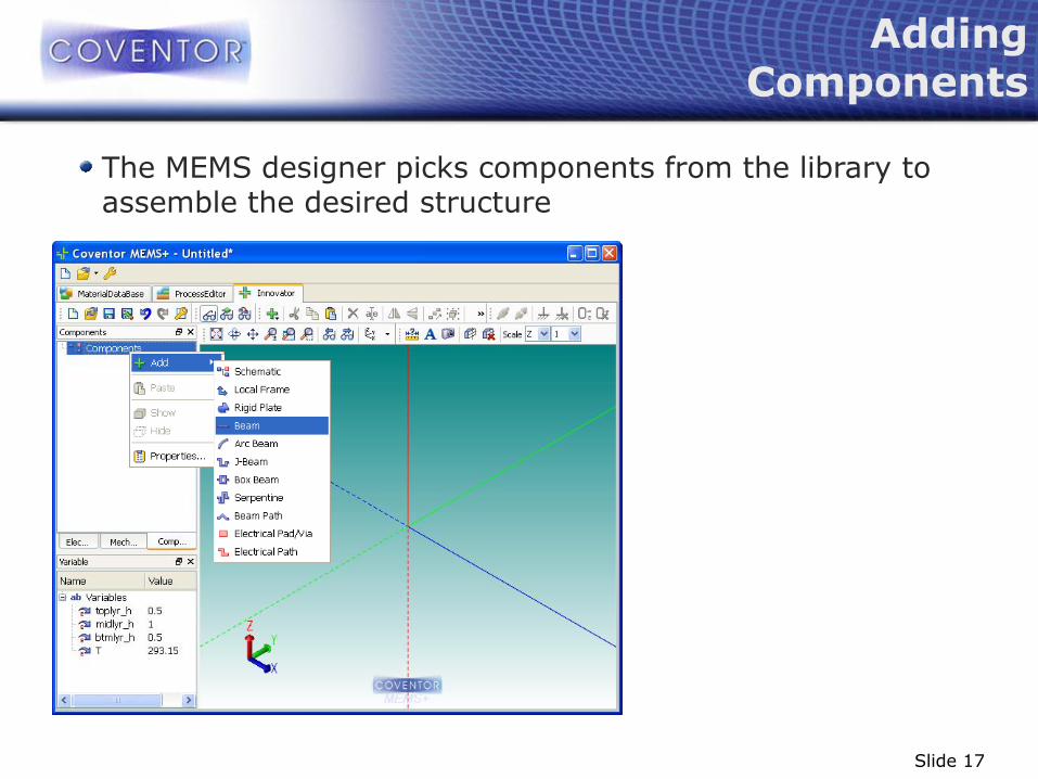
The MEMS designer picks components from the library to assemble the desired structure
Adding Components

Slide 18
Each component can be assigned to one or multiple layers of the corresponding process file
Layer Assignment

Slide 19
Component parameters can be defined as values, variables or algebraic equations
Component Parameters
Slide 20
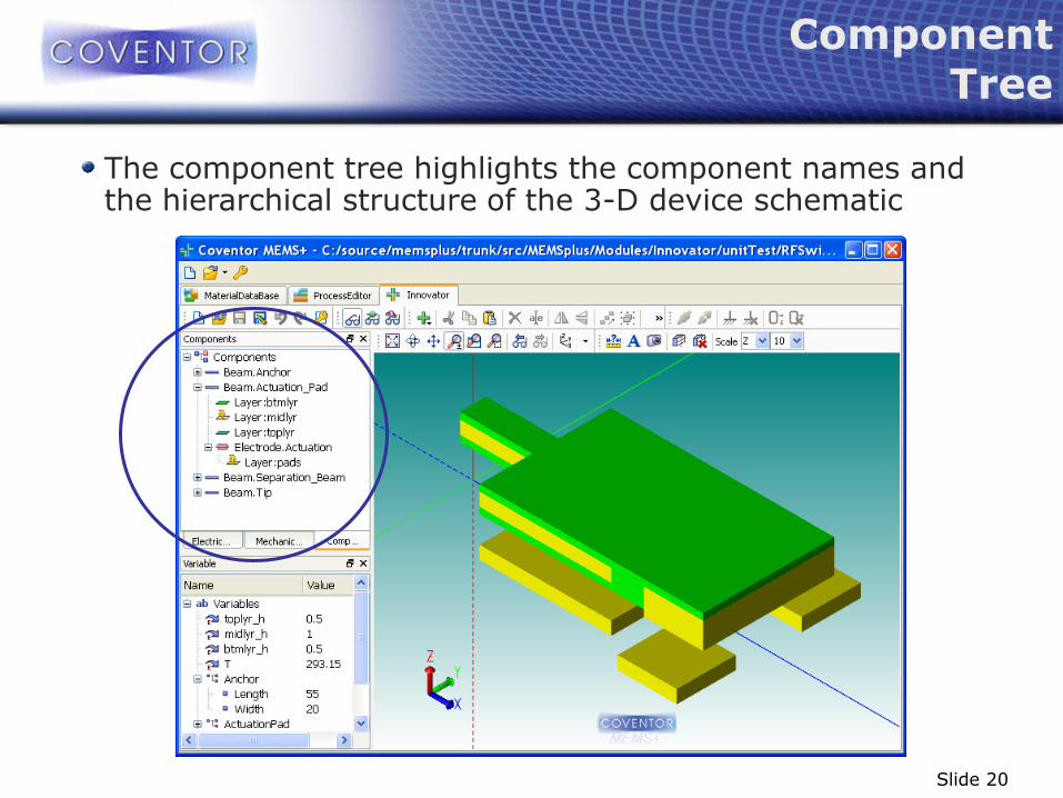
Component Tree
The component tree highlights the component names and the hierarchical structure of the 3-D device schematic

Slide 21
Mechanical Connector View
The mechanical connector tree and viewing mode highlights which components are linked together
Slide 22
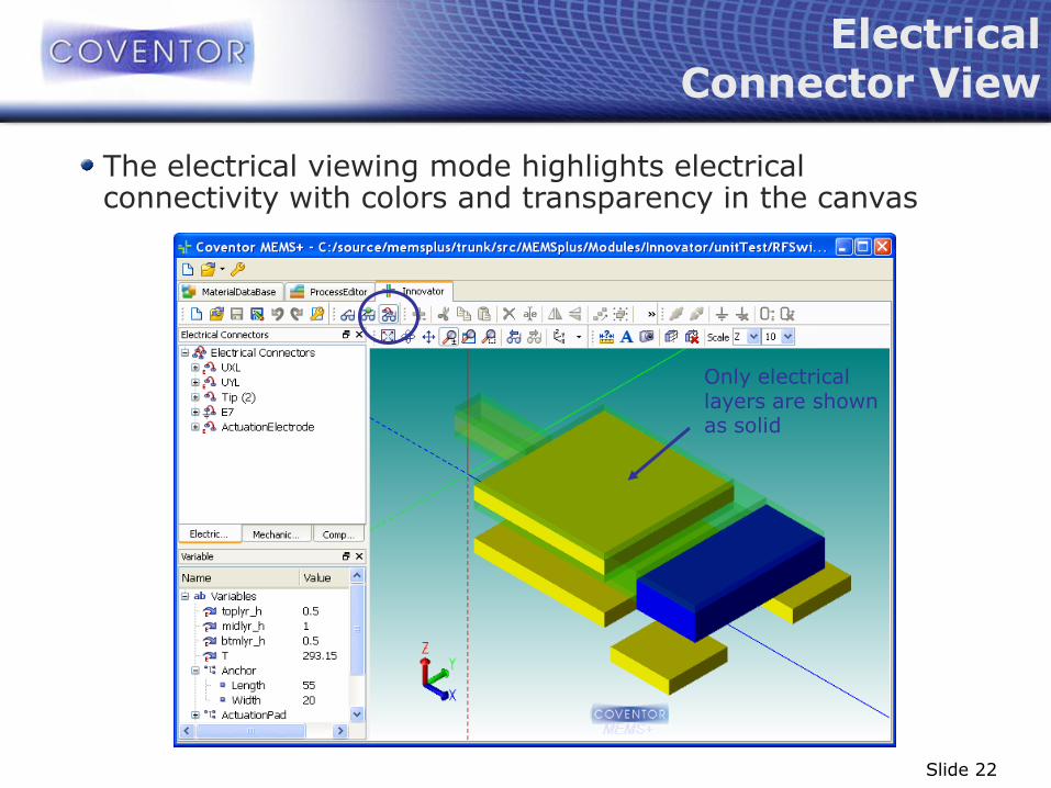
Electrical Connector View
The electrical viewing mode highlights electrical connectivity with colors and transparency in the canvas
Only electrical layers are shown as solid

Slide 23
3D Innovator designs can be imported into the Cadence Library Manager …
Cadence Virtuoso Cell Generation

Slide 24
3D Innovator designs can be imported into the Cadence Library Manager using the MEMS+ import tool
Cadence Virtuoso Cell Generation
Slide 25
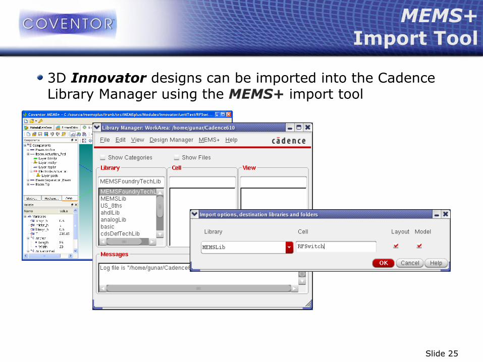
3D Innovator designs can be imported into the Cadence Library Manager using the MEMS+ import tool
MEMS+ Import Tool

Slide 26
The MEMS+ import tool automatically creates a parametric layout and schematic view
Parametric Cell Views

Slide 27
The MEMS device cell in Virtuoso features all parameters that were exposed in MEMS+
Virtuoso Cell Parameters
Slide 28
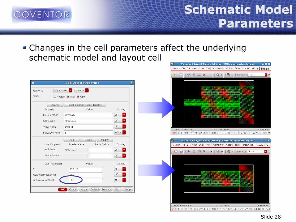
Schematic Model Parameters
Changes in the cell parameters affect the underlying schematic model and layout cell
Schematic Model Parameters

Slide 29
The symbol view features all exposed electrical and mechanical ports
Electrical Pins

Slide 30
The symbol view features all exposed electrical and mechanical ports
Mechanical Pins

Slide 31
The MEMS designer adds electrical and mechanical boundary conditions to the exposed model pins
MEMS Device Schematic

Slide 32
The MEMS designer confirms the device performance running DC, AC and transient simulations
MEMS Device Simulation
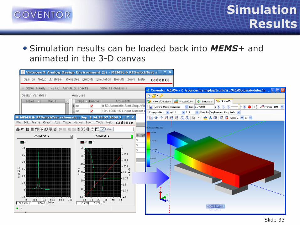
Slide 33
Simulation results can be loaded back into MEMS+ and animated in the 3-D canvas
Simulation Results
Slide 34
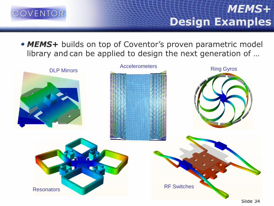
MEMS+ Design Examples
DLP Mirrors Ring Gyros
RF Switches Resonators
Accelerometers
MEMS+ builds on top of Coventor’s proven parametric model library and can be applied to design the next generation of …