mems assign
9
MICROMECHANICAL FILTERS The basic principles described so far for mechanical filters can be used in the design their micro-sized counterparts. However, the accuracy of these formulations is plausible at the micro scale for reasons such as the structural dimensions being not large enough compared with wavelength, nonidealities of boundary conditions and other nonlinear effects. Non etheless the se for mul ati ons are def inite ind icators for und ers tan din g the operational principles of these micro devices. The goal is to fabricate devices such as filters so small that they can be integrated into rest of the circuit in a single chip leading to a ‘system-on-a-chip’. Conventional filters using crystal oscillators are not amenable to such miniat uri zat ion . Hen ce a la rge r emp has is has bee n put on min iat uri zat ion of mechanical filters, using standard IC fabrication techniques, so that they can be integrated with other circuits easily. The per for mance for mic romach ine d fil ter s is enh anc ed by usi ng a ser ies of resonator tanks connected together with coupling networks. In general, the number of such tanks used is equal to the (order of filter is the order of its polynomial transfer function). The higher this number the better the frequency selectivity for the filter. But the insertion loss is simultaneously degraded, which can, however, be improved by designing the filter with very large Q factors. Only electrostatically actuated devices are discussed in this section, although the possibility of using other schemes may not be ruled out. A parallel plate capacitor configuration is common for such large electromechanical filters. However, an additional possibility exists for micro devices, where electrostatic comb drives vibrating in a plane parallel to the substrate can be fabricated 1.Electrostatic comb drive An electrostatically driven parallel plate actuator has a clamped-clamped beam configuration. This configuration has nonlinear response characteristics. This nonlinearity can cause frequency instability in the filter operation . Hence another electrostatically actuated structure is preferred at the microscale.
Transcript of mems assign

8/7/2019 mems assign
http://slidepdf.com/reader/full/mems-assign 1/9
MICROMECHANICAL FILTERS
The basic principles described so far for mechanical filters can be used in the
design their micro-sized counterparts. However, the accuracy of these formulations
is plausible at the micro scale for reasons such as the structural dimensions being
not large enough compared with wavelength, nonidealities of boundary conditionsand other nonlinear effects.
Nonetheless these formulations are definite indicators for understanding the
operational principles of these micro devices.
The goal is to fabricate devices such as filters so small that they can be integrated
into rest of the circuit in a single chip leading to a ‘system-on-a-chip’.
Conventional filters using crystal oscillators are not amenable to such
miniaturization. Hence a larger emphasis has been put on miniaturization of
mechanical filters, using standard IC fabrication techniques, so that they can beintegrated with other circuits easily.
The performance for micromachined filters is enhanced by using a series of
resonator tanks connected together with coupling networks. In general, the number
of such tanks used is equal to the (order of filter is the order of its polynomial
transfer function).
The higher this number the better the frequency selectivity for the filter. But the
insertion loss is simultaneously degraded, which can, however, be improved by
designing the filter with very large Q factors.
Only electrostatically actuated devices are discussed in this section, although thepossibility of using other schemes may not be ruled out. A parallel plate capacitor
configuration is common for such large electromechanical filters. However, an
additional possibility exists for micro devices, where electrostatic comb drives
vibrating in a plane parallel to the substrate can be fabricated
1.Electrostatic comb drive
An electrostatically driven parallel plate actuator has a clamped-clamped beam
configuration.
This configuration has nonlinear response characteristics. This nonlinearity can
cause frequency instability in the filter operation . Hence another electrostatically
actuated structure is preferred at the microscale.

8/7/2019 mems assign
http://slidepdf.com/reader/full/mems-assign 2/9
The layout of such a laterally driven electrostatic resonant structure is shown in
Figure
Two resonator configurations are possible with this structure
In the first, a two-port configuration, the structure is driven on one of the comb
structures and sensed at the other, for capacitance variations. In the second
configuration, both comb structures are used to drive differentially, while sensing
is achieved by monitoring shift in impedance at resonance.
The folded beam truss suspension has large compliance and is capable of
reducing the residual strain in the structural film.
In the two-port configuration, the driving force and the sensitivity of the output are
both proportional to the variation of capacitance with lateral displacement ∂C/∂x.
static displacement at the drive port, for an applied drive voltage vD,
x=Fx/k s=(1/2 k s) vD2(∂C/∂x.)
Lateral electrostatic comb actuator
where Fx is the x component of
the electrostatic force and k s is
the spring constant of the
system. Assuming the trusses
that join the folded beam are
rigid, the spring constant is
obtained analytically a
To ensure stability, the drive voltage consists of an ac voltage of amplitude vd
superimposed on a dc bias V P such that
vD = V P + vd sin ωt
It may be mentioned at this point that realization of a small interelectrode gap is
essential to reduce the drive voltage requirements of this actuation mechanism. A

8/7/2019 mems assign
http://slidepdf.com/reader/full/mems-assign 3/9
fabrication technique using combination of oxidation machining with a suitable
post-release positioning has been developed to address this issue
Submicron gaps can be achieved by this approach.
time derivative, we get
∂x/∂t = (1/2k s) (∂C/∂x) ( 2V Pvdω cos ωt + v2dω sin 2ωt)
For ac voltages much smaller than the dc bias, the second harmonic term on the
right-hand side can be neglected. At resonance, the magnitude is multiplied by the
quality factor, to get the magnitude of the electromechanical transfer function
which relates the phasor displacement X to the phasor drive voltage V d:
The quality factor for this structure is estimated to be
The sensed current is at the output port is
The resonant frequency of the structure is determined by Rayleigh method as
Their fabrication uses a single mask for most of the critical features; this eases the
process design and can potentially reduce cost.
The parasitic capacitive coupling between the input and output ports is minimized

8/7/2019 mems assign
http://slidepdf.com/reader/full/mems-assign 4/9
by including a grounded planar electrode, which also helps suppress excitation of
undesired modes
2.Micromechanical filters using comb drives
A number of resonant structures can be coupled together in either series or parallel
configuration to obtain high-quality filter characteristics. Schematics for these
configurations are shown . In the series filter, a square truss coupling
spring connects the two resonators. In the parallel configuration of band pass filter,
the input and output terminals of the resonators are connected in parallel such that
the output
(a) Series and (b) parallel combination of resonators
(b)currents are added up. A notch filter can also be realized in a similar way, by
adding the
(c) currents in opposite phases.
(d)In this analysis, mass of the coupling beam is assumed negligible. The
bandwidth
(e) of the filter depends on the ratio of stiffness of the coupling beam (k sij ) to
that of the(f) resonator beam (k r).
Bandwidth=f L k sij/ k nij k r

8/7/2019 mems assign
http://slidepdf.com/reader/full/mems-assign 5/9
where f L is the filter center frequency and k nij is the normalized coupling
coefficient used in filter design. These resonators are designed to have slightly
different resonan frequencies such that their difference is related to the Q factor
f 2 − f 1=f1/Q1
This ensures flat and symmetrical band pass characteristics, provided the
individual resonators have identical 3-dB bandwidths and resonance amplitudes. In
other words, the difference in frequencies is equal to the 3-dB bandwidth of the
filter. To obtain a steep roll-off and flat pass band characteristics, a large number
of resonators should be connected in parallel. In terms of the highest and lowest
resonant frequencies, f u and f L,
respectively, the number of resonators is obtained as
N = Q(f u – f L)/f L
filter with n resonators coupled in series, the overall transfer function
A mechanical model and the corresponding electrical equivalent circuit for the
filter configuration. The equivalent mass, spring constant and dampingconstant for ith resonator in the mechanical model are expressed in terms of the
physical parameters
where M pi is the mass of the plate and M bi is that of the folded beams at the ith
resonator; wi and Li are, respectively, the width and length of the folded
suspension in the ith resonator; h is the thickness of the polysilicon structures and

8/7/2019 mems assign
http://slidepdf.com/reader/full/mems-assign 6/9
E p is its Young’s modulus. The stiffness of the coupling spring is similarly
obtained as:
Making use of the electromechanical mobility analogy described in
parameters in the electrical equivalent circuits are related to the above mechanical
parameters

8/7/2019 mems assign
http://slidepdf.com/reader/full/mems-assign 7/9
Photograph and (b) equivalent circuits of micromechanical filters
where the transformation parameter η for the filter is defined as
The amplification factor in the electrical equivalent circuit
To avoid the problems associated with stiction and deterioration of electrodes
during operation, an electrostatic repulsive actuator has been recently developed
The repulsive force in this is generated by the asymmetry of the in-plane electric
field causing the movable electrode to slide in the direction shown. The
8/7/2019 mems assign
http://slidepdf.com/reader/full/mems-assign 8/9
force generated, resonant frequency and quality factor of this configuration are
generally derived using finite elements analysis
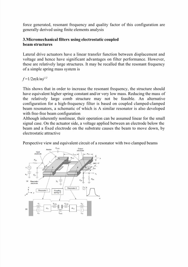
3.Micromechanical filters using electrostatic coupled
beam structures
Lateral drive actuators have a linear transfer function between displacement and
voltage and hence have significant advantages on filter performance. However,
these are relatively large structures. It may be recalled that the resonant frequency
of a simple spring mass system is
f =1/2π(k/m)1/2
This shows that in order to increase the resonant frequency, the structure should
have equivalent higher spring constant and/or very low mass. Reducing the mass of the relatively large comb structure may not be feasible. An alternative
configuration for a high-frequency filter is based on coupled clamped-clamped
beam resonators, a schematic of which is A similar resonator is also developed
with free-free beam configuration
Although inherently nonlinear, their operation can be assumed linear for the small
signal case. On the actuator side, a voltage applied between an electrode below the
beam and a fixed electrode on the substrate causes the beam to move down, by
electrostatic attractive
Perspective view and equivalent circuit of a resonator with two clamped beams

8/7/2019 mems assign
http://slidepdf.com/reader/full/mems-assign 9/9
This movement of the beam is coupled towards the next beam, which operates as
a capacitive transducer that senses the displacement of the beam.
The dynamic analysis of clamped-clamped beam presented earlier in this chapter is
valid for these micro structures as well. The input voltage consists of dc bias V P
and a dynamic ac signal vd.
The resonant frequency can be obtained
The quality factor of the resulting filter is
The dynamic spring constant k c of the beam varies with distance from anchor
points.
Thus to improve the quality factor of the filter, the coupling beam is not attached at
the center of the beams. Instead it is attached at a point closer to the anchor point,
where the dynamic spring constant is higher and thus the filter Q factor. As with
the previous case, the length of the coupling beam is taken as quarter acoustic
wavelength. The coupling in this case is therefore modeled as: