Memory Layout and SLC500™ System Addresses - …engineering.richmondcc.edu/Courses/ELC … · PPT...
60
Memory Layout and Memory Layout and SLC500™ System SLC500™ System Addresses Addresses
Transcript of Memory Layout and SLC500™ System Addresses - …engineering.richmondcc.edu/Courses/ELC … · PPT...

Memory Layout and Memory Layout and SLC500™ System SLC500™ System
AddressesAddresses

Processor Memory Processor Memory DivisionDivision• An SLC 500 processor's memory is An SLC 500 processor's memory is
divided into two storage areas. Like divided into two storage areas. Like two drawers in a filing cabinet, one two drawers in a filing cabinet, one area is for data files and the other area is for data files and the other for program files. Processor memory for program files. Processor memory division and file capacity are shown division and file capacity are shown in the following graphic:in the following graphic:

Program FilesProgram Files
• Program files contain processor Program files contain processor information, the main ladder information, the main ladder program, and other ladder files. An program, and other ladder files. An SLC 500 processor can contain up to SLC 500 processor can contain up to 256 program files. Program files are 256 program files. Program files are located in the Program Files folder located in the Program Files folder of the RSLogix 500 project tree, as of the RSLogix 500 project tree, as shown in the following graphic:shown in the following graphic:


• Program files are assigned as follows:Program files are assigned as follows:• File 0 always contains system File 0 always contains system
information.information.• File 1 is reserved.File 1 is reserved.• File 2 contains the main ladder file.File 2 contains the main ladder file.• File 3-255 contains other ladder files File 3-255 contains other ladder files
(subroutines).(subroutines).

Data FilesData Files
• DataData files contain the status files contain the status information associated with external information associated with external I/O and all other instructions used in I/O and all other instructions used in the main and subroutine ladder the main and subroutine ladder program files. Data files are located program files. Data files are located in the Data Files folder of the in the Data Files folder of the RSLogix 500 project tree, as shown RSLogix 500 project tree, as shown in the following graphic:in the following graphic:

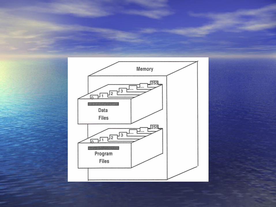
• Data files are assigned as follows:Data files are assigned as follows:• File O0 stores the state of output terminals.File O0 stores the state of output terminals.• File II stores the state of input terminals.File II stores the state of input terminals.• File S2 stores processor operation data.File S2 stores processor operation data.• File B3 stores internal relay logic.File B3 stores internal relay logic.• File T4 stores the timer accumulator and preset values and status File T4 stores the timer accumulator and preset values and status
bits.bits.• File C5 stores the counter accumulator and preset values and File C5 stores the counter accumulator and preset values and
status bits.status bits.• File R6 stores the length, pointer position, and status bits for File R6 stores the length, pointer position, and status bits for
specific instructions such as shift registers.specific instructions such as shift registers.• File N7 stores whole number values, both negative and positive or File N7 stores whole number values, both negative and positive or
bit-level information.bit-level information.• File F8 stores positive and negative numbers that include aFile F8 stores positive and negative numbers that include a
decimal point.decimal point. ,,• Files 9-255 store user-defined data.Files 9-255 store user-defined data.

SLC 500 Processor Data SLC 500 Processor Data Storage Units:Storage Units:
• The SLC 500 processor stores data in the following units The SLC 500 processor stores data in the following units of memory:of memory:
• Bit:Bit: A digit in the binary radix (0 or 1). A bit may A digit in the binary radix (0 or 1). A bit may represent the state, on or off, of a discrete I/O device.represent the state, on or off, of a discrete I/O device.
• WordWord: : A sequence of 16 bits that is treated as a unit. For A sequence of 16 bits that is treated as a unit. For example, the 16 bits representing the 16 points of an I/O example, the 16 bits representing the 16 points of an I/O module comprise one word.module comprise one word.
• ElementElement: : A word or group of words that work together as A word or group of words that work together as a unit.a unit.
• Sub-elementSub-element: : Individual words within an element.Individual words within an element.TypeType: : A group of words or elements with a common A group of words or elements with a common usage usage
• FileFile: A consecutive array of words addressable as a unit.: A consecutive array of words addressable as a unit.

SLC 500 Software Address SLC 500 Software Address Characteristics:Characteristics:
• SLC 500 software addresses (internal storage SLC 500 software addresses (internal storage addresses) are used for processor and addresses) are used for processor and program control. A software address is a program control. A software address is a value stored within a processor's data file that value stored within a processor's data file that is not directly connected to real-world inputs is not directly connected to real-world inputs or outputs.or outputs.
• The following SLC 500 software address The following SLC 500 software address format is used for bits stored in status, binary, format is used for bits stored in status, binary, timer, counter, control, integer and floating timer, counter, control, integer and floating point data table files:point data table files:

SLC 500 Hardware Address SLC 500 Hardware Address Characteristics:Characteristics:
• The address for a real-world device (input or output) is The address for a real-world device (input or output) is directly determined by the module slot number and directly determined by the module slot number and terminal to which the hardware device is wired.terminal to which the hardware device is wired.
• Slot numbers are assigned from left to right, beginning Slot numbers are assigned from left to right, beginning with 0. The SLC 500 processor is in slot 0.with 0. The SLC 500 processor is in slot 0.
• A hardware address contains the following information:A hardware address contains the following information:• The module type, either an input (I) or an output (O) The module type, either an input (I) or an output (O)
modulemodule• The slot number (numbered in decimal from 1 to 30)The slot number (numbered in decimal from 1 to 30)• The terminal number (numbered in decimal from 0 to 15)The terminal number (numbered in decimal from 0 to 15)

I/O Addresses:I/O Addresses:
• The input and output data tables store the states of The input and output data tables store the states of input and output devices. The two files have the input and output devices. The two files have the following characteristics:following characteristics:
• Each I/O module terminal point is represented by a Each I/O module terminal point is represented by a bit stored in either the input or output data tables.bit stored in either the input or output data tables.
• The bits in the input data table store data from input The bits in the input data table store data from input modules; bits in the output data table store data modules; bits in the output data table store data going to the output modules.going to the output modules.
• If a bit has a value of 1, it means the terminal point If a bit has a value of 1, it means the terminal point it represents is "on." If a bit has a value of 0, it it represents is "on." If a bit has a value of 0, it means the terminal point it represents is "off."means the terminal point it represents is "off."


The following graphic illustrates the relationship between a The following graphic illustrates the relationship between a 16-point input module and the input data table: For modules 16-point input module and the input data table: For modules with more than 16 terminal points, a ".1" is added to the slot with more than 16 terminal points, a ".1" is added to the slot number column of the data table to indicate the row number column of the data table to indicate the row containing terminals 16 and beyond.containing terminals 16 and beyond.

Determine SLC 500 Determine SLC 500 Hardware Addresses:Hardware Addresses:
• The following graphic shows an SLC The following graphic shows an SLC 500 hardware address for terminal 500 hardware address for terminal number 10 of an input module in slot number 10 of an input module in slot 3. In the example, note the position 3. In the example, note the position and order of the module type, slot and order of the module type, slot number, and terminal number:number, and terminal number:


Example of Input addressingExample of Input addressing

Example of Output Example of Output addressingaddressing

Example of I/O addressingExample of I/O addressing

Example of Output Example of Output addressingaddressing

Determine SLC 500 Determine SLC 500 Software Addresses:Software Addresses:
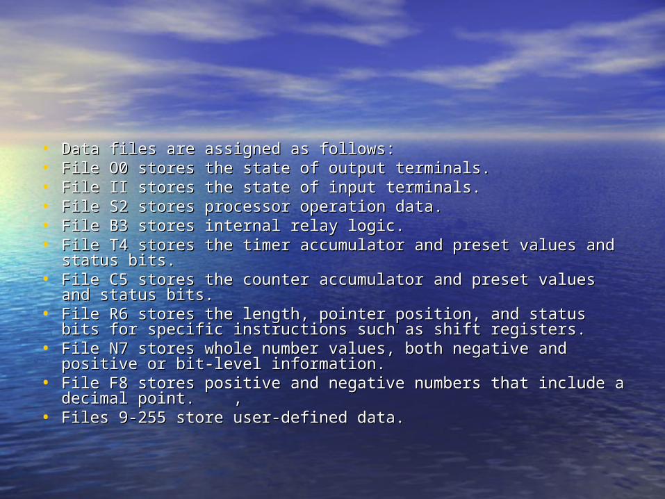
• The following graphic shows an SLC The following graphic shows an SLC 500 software address for the 2nd bit 500 software address for the 2nd bit in the 3rd word in binary file 15. In in the 3rd word in binary file 15. In the example, note the position and the example, note the position and order of the file type, file number, order of the file type, file number, word or element, and bit number:word or element, and bit number:
Example of Bit addressingExample of Bit addressing
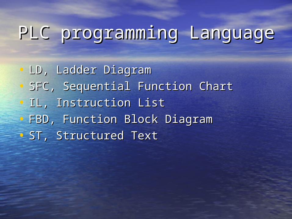
PLC programming LanguagePLC programming Language• LD, Ladder DiagramLD, Ladder Diagram• SFC, Sequential Function ChartSFC, Sequential Function Chart• IL, Instruction ListIL, Instruction List• FBD, Function Block DiagramFBD, Function Block Diagram• ST, Structured TextST, Structured Text

SLC 500 Processor Operating SLC 500 Processor Operating CycleCycle
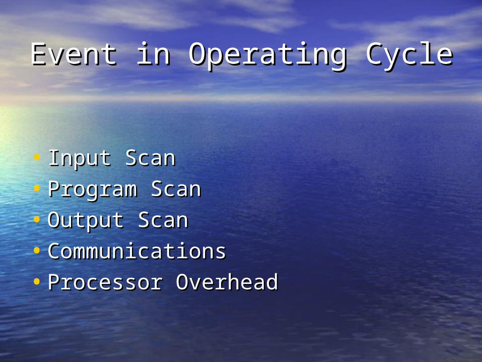
Event in Operating CycleEvent in Operating Cycle
• Input ScanInput Scan• Program ScanProgram Scan• Output ScanOutput Scan• CommunicationsCommunications• Processor OverheadProcessor Overhead

Drafting RLLDrafting RLL

• The status of each input module is read, and the input The status of each input module is read, and the input image table in the processor is image table in the processor is updated with the updated with the information.information.
• The ladder program is executed. The input image table is The ladder program is executed. The input image table is evaluated to see which conditions are met. Resulting evaluated to see which conditions are met. Resulting information is written to the output table; however, no information is written to the output table; however, no information is transferred to the output information is transferred to the output module until all module until all rungs have been read. rungs have been read. The output image table information The output image table information is transferred to the output module affecting is transferred to the output module affecting real-world real-world outputs.outputs.
• Communications with computer and other Communications with computer and other network devices network devices takes place.takes place.
• Internal housekeeping in the processor takes place, Internal housekeeping in the processor takes place, including updates of the status file and internal time base.including updates of the status file and internal time base.
• Important:Important:• Data concerning outputs is only written to the data table Data concerning outputs is only written to the data table
during the program scan. Outputs are not actually during the program scan. Outputs are not actually updated until the output scan.updated until the output scan.
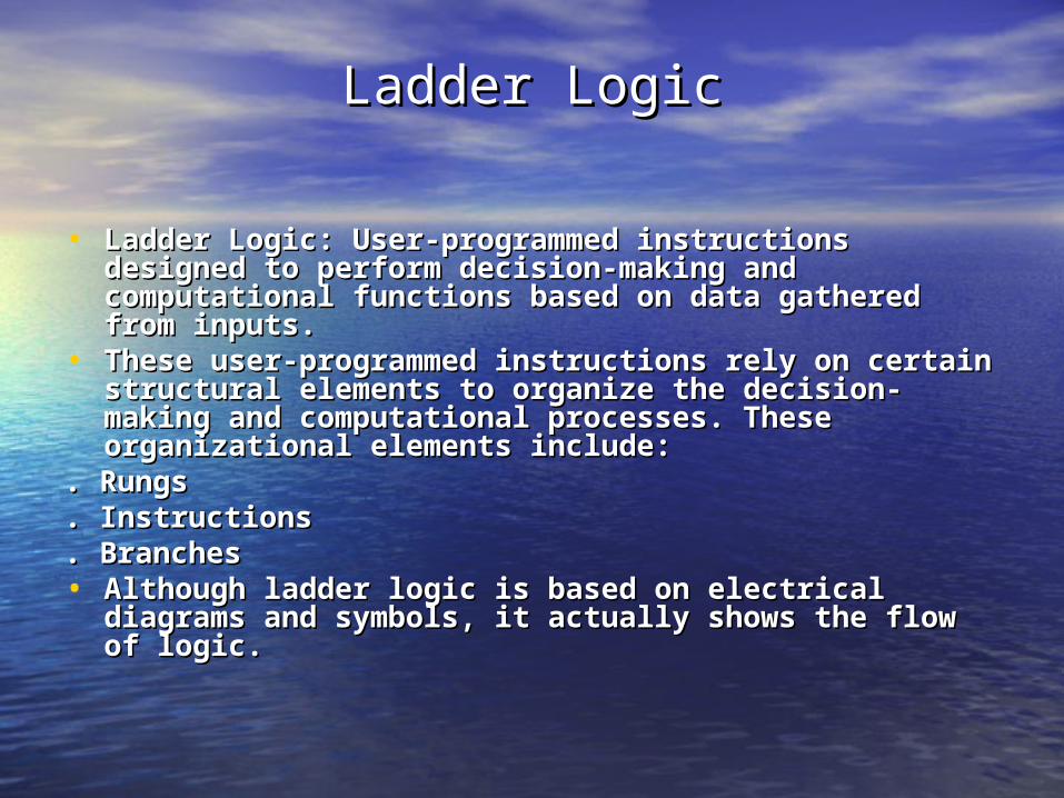
Ladder LogicLadder Logic
• Ladder Logic: User-programmed instructions Ladder Logic: User-programmed instructions designed to perform decision-making and designed to perform decision-making and computational functions based on data gathered computational functions based on data gathered from inputs.from inputs.
• These user-programmed instructions rely on certain These user-programmed instructions rely on certain structural elements to organize the decision-making structural elements to organize the decision-making and computational processes. These organizational and computational processes. These organizational elements include:elements include:
. Rungs. Rungs
. Instructions. Instructions
. Branches. Branches• Although ladder logic is based on electrical diagrams Although ladder logic is based on electrical diagrams
and symbols, it actually shows the flow of logic.and symbols, it actually shows the flow of logic.
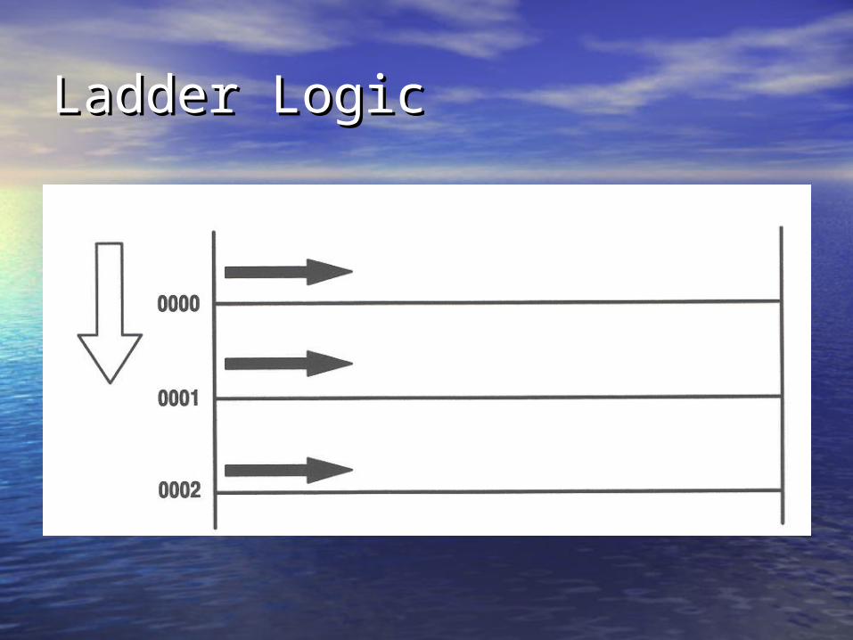
Ladder LogicLadder Logic

Electromechanical Relay Ladder Electromechanical Relay Ladder DiagramDiagram

Drafting Ladder LogicDrafting Ladder Logic


BranchesBranches• When placing branches in ladder logic, keep these key points When placing branches in ladder logic, keep these key points
in mind:in mind:• Branches are read from left to right, top to bottom.Branches are read from left to right, top to bottom.• A branch can be used to create a different path for reading A branch can be used to create a different path for reading
inputs. inputs. • A branch can be used to program multiple outputs.A branch can be used to program multiple outputs.• A branch must start and end on the same level.A branch must start and end on the same level.• A parallel branch has the same start and same end point as A parallel branch has the same start and same end point as
thethe branch it is below:branch it is below:• Parallel branches are evaluated faster than nested branches. Parallel branches are evaluated faster than nested branches.
The number of parallel branches is limited by the processor The number of parallel branches is limited by the processor memory.memory.
• A nested branch starts and ends inside the same branch.A nested branch starts and ends inside the same branch.• Nested branches are limited to fourNested branches are limited to four


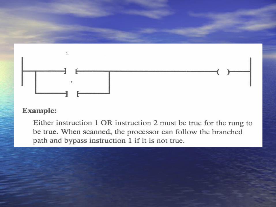

AND with OR logicAND with OR logic

OutputsOutputs

Last Rung RuleLast Rung Rule•When programming an output on more When programming an output on more than one rung, be careful tokeep the than one rung, be careful tokeep the following rule in mind:following rule in mind:
•Data concerning the state of an output is Data concerning the state of an output is written to the data table after rungs are written to the data table after rungs are evaluated. However, the actual outputs are evaluated. However, the actual outputs are not updated until the output scan. Because not updated until the output scan. Because of this, the last state of the output in the of this, the last state of the output in the data table will be the state of the output.data table will be the state of the output.

OutputOutput• Multiple OutputsMultiple Outputs• If one condition determines one or If one condition determines one or
more outputs, do not program them more outputs, do not program them on separate rungs. Use parallel on separate rungs. Use parallel branches to program multiple branches to program multiple outputs as shown in the following outputs as shown in the following example:example:


Outputs that Require Separate Outputs that Require Separate Inputs:Inputs:
If outputs share common inputs, enter the If outputs share common inputs, enter the common inputs once. Use a branch to place common inputs once. Use a branch to place any additional condition(s):any additional condition(s):

ExampleExample
• Both outputs require instruction A and B to be Both outputs require instruction A and B to be true; however, thetrue; however, the
• path to output Y also requires instruction C to be path to output Y also requires instruction C to be true.true.

Example of sealing circuit (logic)Example of sealing circuit (logic)
• When A and B are true, the rung is true. Once the rung is true, itWhen A and B are true, the rung is true. Once the rung is true, it• will remain true until condition B goes false and breaks the seal.will remain true until condition B goes false and breaks the seal.• This type of seal-in logic is used often in programming. For This type of seal-in logic is used often in programming. For
example, if a momentary push button is used to turn X on, X will example, if a momentary push button is used to turn X on, X will remain on even if the operator releases the push button.remain on even if the operator releases the push button.

General Tips for Drafting General Tips for Drafting Ladder LogicLadder Logic
• Ladder logic rarely goes directly Ladder logic rarely goes directly from the programmer's head to the from the programmer's head to the computer without causing rework. computer without causing rework. Try to write out your ladder logic Try to write out your ladder logic first.first.

ExamplesExamplesX = A(BC+D)EX = A(BC+D)E


X=Y=ABCX=Y=ABC

X =(AB+D)CX =(AB+D)C

X=A+BCX=A+BCY=(A+BC)DY=(A+BC)D

X=(A+B+C+D)(E+F)X=(A+B+C+D)(E+F)

X=(A+C)BX=(A+C)B


ExamplesExamples1. 1. Conditions A or B or C or Conditions A or B or C or D, D, and E or F turn on and E or F turn on
output X.output X.2. Condition A and condition B, or state of output X, and 2. Condition A and condition B, or state of output X, and
condition B, turns on output X.condition B, turns on output X.3. Condition A turns on output X. Conditions A and B 3. Condition A turns on output X. Conditions A and B
and C and D turn on output Y. Conditions A and B, and C and D turn on output Y. Conditions A and B, and E turn on output Z.and E turn on output Z.
4. Conditions A and B and C, or D and B and C, or E and 4. Conditions A and B and C, or D and B and C, or E and F, turn on output X.F, turn on output X.

Efficient Instruction Efficient Instruction Arrangement on Rungs and Arrangement on Rungs and BranchesBranches• Rule: When the processor Rule: When the processor
encounters a false instruction on encounters a false instruction on a rung, ita rung, it
• stops scanning the rung and stops scanning the rung and moves to the next rung of logic:moves to the next rung of logic:
• For best performance: Sequence For best performance: Sequence series instructions from the most series instructions from the most likely to be false (at left) to least likely to be false (at left) to least likely to be false (at right).likely to be false (at right).

Efficient Arrangement of Efficient Arrangement of Multiple BranchesMultiple Branches• Rule: As soon as the processor Rule: As soon as the processor
finds a true path, it will stopfinds a true path, it will stop• scanning and will not read any scanning and will not read any
remaining branches:remaining branches:
• For best performance: If your For best performance: If your rung contains parallel rung contains parallel branches, place the path that branches, place the path that is most often true on the top.is most often true on the top.