Memorie Sinterizzazione Direct Metal Laser Sintering… · Sinterizzazione Direct Metal Laser...
10
La Metallurgia Italiana - n. 10/2013 15 Sinterizzazione Direct Metal Laser Sintering: an additive manufacturing technology ready to produce lightweight structural parts for robotic applications D. Manfredi, F. Calignano, E. P. Ambrosio, M.Krishnan, R. Canali, S. Biamino, M. Pavese, E. Atzeni, L. Iuliano, P. Fino, C. Badini Keywords: Additive manufacturing (AM) - Direct metal laser sintering (DMLS) - Aluminium alloy - Mechanical properties - Electron microscopy - Lightweight structures D. Manfredi, F. Calignano, E. P. Ambrosio, M.Krishnan, R. Canali Center for Space Human Robotics @Polito, Istituto Italiano di Tecnologia, Corso Trento, 21, 10129 Torino, Italy (corresponding author: tel.: 011 0903406; fax.: 011 0903401; e-mail address: [email protected]) S. Biamino, M. Pavese, P. Fino, C. Badini Dipartimento Scienza Applicata e Tecnologia, Politecnico di Torino, Corso Duca degli Abruzzi 24, 10129, Torino, Italy E. Atzeni, L. Iuliano Dipartimento di Ingegneria Gestionale e della Produzione, Politecnico di Torino, Corso Duca degli Abruzzi 24, 10129, Torino, Italy Memorie Direct metal laser sintering (DMLS) is an additive manufacturing (AM) technology for the fabrication of near net- shaped parts directly from computer-aided design (CAD) data by melting together different layers with the help of a laser source. Its application for manufacturing three- dimensional objects represents one of the promising directions to solve challenging industrial problems. This approach permits to extend significantly the freedom of design and manufacture by allowing, for example, to create an object with desired shape and internal structure in a single fabrication step. The design of the part can be tailored to meet specific functions and properties (e.g. physical, mechanical, chemical, biological, etc.) using different materials. In this paper a DMLS machine was used for robotic lightweight components fabrication in an aluminium alloy. It was observed that DMLS technology not only achieved very interesting mechanical properties thanks to the very fine microstructure, but also can easily promote the development and study of lightweight lattice structures. In addition, it is envisaged to develop new custom materials, such as light metal matrix composites, suitable for the DMLS process, broadening the range of applications in different fields like space, aviation, automotive and other industries. INTRODUCTION AND GENERAL OVERVIEW Near net shape manufacturing technologies for metals produce components close to the finished size and shape, requiring a minimum amount of finishing processes. Such processes include Closed Die Forging, Investment Cast- ing, metal injection moulding (MIM) and, more recently, additive manufacturing (AM). According to the Wohlers [1], the interest in AM systems for metal part production is still growing, with an increasing attraction for a wide range of fields of applications. Using AM production techniques can lead to significant business benefits, such as time and cost savings due to tooling reduction, virtually unlimited geometric complexities, new design freedom, and less pro- duction of waste with respect to traditional manufacturing processes. The development of new energy sources was fundamental for bringing the potential of the processes to fruition, capable now of obtaining fully dense metal parts that rival those of wrought materials: as an example, se- lective laser melting (SLM) has taken over selective laser sintering (SLS) due to the availability of fiber laser tech- nologies (powder particles can now be fully melted and not only sintered) and it is constantly developing through vigorous in-house and university-based research [2,3]. The first SLM system was introduced by Fockele and Schwarze (F&S) from Germany in 1999: this was a stainless steel powder-based system, developed in collaboration with the Fraunhofer Institute for Laser Technology. Considering the laser as an energy source, also the direct laser fabrica- tion (DLF) processes could be considered AM techniques to produce metal parts: in the well-known Blown Powder method [4], 3D components are built-up layer-by-layer us-
-
Upload
nguyenkhanh -
Category
Documents
-
view
212 -
download
0
Transcript of Memorie Sinterizzazione Direct Metal Laser Sintering… · Sinterizzazione Direct Metal Laser...

La Metallurgia Italiana - n. 10/2013 15
Sinterizzazione
Direct Metal Laser Sintering: an additive manufacturing technology ready to produce
lightweight structural parts for robotic applications
D. Manfredi, F. Calignano, E. P. Ambrosio, M.Krishnan, R. Canali, S. Biamino, M. Pavese, E. Atzeni, L. Iuliano, P. Fino, C. Badini
Keywords: Additive manufacturing (AM) - Direct metal laser sintering (DMLS) - Aluminium alloy -Mechanical properties - Electron microscopy - Lightweight structures
D. Manfredi, F. Calignano, E. P. Ambrosio, M.Krishnan, R. Canali
Center for Space Human Robotics @Polito, Istituto Italiano di Tecnologia, Corso Trento, 21, 10129 Torino, Italy
(corresponding author: tel.: 011 0903406; fax.: 011 0903401; e-mail address: [email protected])
S. Biamino, M. Pavese, P. Fino, C. Badini
Dipartimento Scienza Applicata e Tecnologia, Politecnico di Torino, Corso Duca degli Abruzzi 24,
10129, Torino, Italy
E. Atzeni, L. Iuliano
Dipartimento di Ingegneria Gestionale e della Produzione, Politecnico di Torino, Corso Duca degli
Abruzzi 24, 10129, Torino, Italy
Memorie
Direct metal laser sintering (DMLS) is an additive manufacturing (AM) technology for the fabrication of near net-shaped parts directly from computer-aided design (CAD) data by melting together different layers with the help of a laser source. Its application for manufacturing three- dimensional objects represents one of the promising directions to solve challenging industrial problems. This approach permits to extend significantly the freedom of design and manufacture by allowing, for example, to create an object with desired shape and internal structure
in a single fabrication step. The design of the part can be tailored to meet specific functions and properties (e.g. physical, mechanical, chemical, biological, etc.) using different materials. In this paper a DMLS machine
was used for robotic lightweight components fabrication in an aluminium alloy. It was observed that DMLS technology not only achieved very interesting mechanical properties thanks to the very fine microstructure, but also can easily promote the development and study of lightweight lattice structures. In addition, it is envisaged
to develop new custom materials, such as light metal matrix composites, suitable for the DMLS process, broadening the range of applications in different fields like space, aviation, automotive and other industries.
INTRODUCTION AND GENERAL OVERVIEW
Near net shape manufacturing technologies for metals produce components close to the finished size and shape, requiring a minimum amount of finishing processes. Such processes include Closed Die Forging, Investment Cast-ing, metal injection moulding (MIM) and, more recently,
additive manufacturing (AM). According to the Wohlers [1], the interest in AM systems for metal part production is still growing, with an increasing attraction for a wide range of fields of applications. Using AM production techniques can lead to significant business benefits, such as time and cost savings due to tooling reduction, virtually unlimited geometric complexities, new design freedom, and less pro-duction of waste with respect to traditional manufacturing processes. The development of new energy sources was fundamental for bringing the potential of the processes to fruition, capable now of obtaining fully dense metal parts that rival those of wrought materials: as an example, se-lective laser melting (SLM) has taken over selective laser sintering (SLS) due to the availability of fiber laser tech-nologies (powder particles can now be fully melted and not only sintered) and it is constantly developing through vigorous in-house and university-based research [2,3]. The first SLM system was introduced by Fockele and Schwarze (F&S) from Germany in 1999: this was a stainless steel powder-based system, developed in collaboration with the Fraunhofer Institute for Laser Technology. Considering the laser as an energy source, also the direct laser fabrica-tion (DLF) processes could be considered AM techniques to produce metal parts: in the well-known Blown Powder method [4], 3D components are built-up layer-by-layer us-

La Metallurgia Italiana - n. 10/201316
Memorie
ing powder fed to the laser focal point, where it is melted and solidified. In this case the path of the laser beam is defined by a CAD file, controlling the movement along x, y and z axes. The main difference is that in the Laser Powder Bed Manufacturing techniques, such as SLM, the powder itself is deposited in thin layers (about 20-30 μm) and se-lectively melted on a substrate to build 3D components from the CAD model.In the last decade, many companies have put machines based on these different systems for the direct melting of a metal powder bed onto the European market: EOS GmbH (Germany) [5,6], MTT Technologies Ltd (UK) [7], Concept Laser GmbH (Germany) and Phenix System (France) [8]. In addition a Swedish company, Arcam AB, has commer-cialized a machine based on a high energy Electron Beam (EBM), high enough to melt a great variety of metals or al-loys like stainless and tool steels, Ni-based and Co-based superalloys, hardmetals, intermetallic compounds, alumi-num, beryllium and niobium [9-11]. In this study a DMLS machine from EOS GmbH, able to process reactive materials such as cobalt–chromium, ti-tanium [12] and even aluminum alloys thanks to its laser power and to the inert atmosphere in the building chamber, was used to fabricate lightweight structures for robotic ap-plications. In fact, one of the main focuses at the Istituto Italiano di Tecnologia Center for Space Human Robotics, is on the development of an exoskeleton to overcome the EVA (Extra Vehicular Activities) glove stiffness of an as-tronaut and help him keep its strength, endurance, and dexterity [13-15]. The device shall be lightweight, reliable, and have minimal bulk and power consumption. Many engineering aspects and skills are required just only for the design and fabrication of the structure, and the DMLS technique seems promising for several reasons:
it allows the fast production of many different proto- –types in a lightweight structural material such as an aluminum alloy, which need to be tested to give feed-back to designers;it involves a new and different method of thinking for –designing, without the compromises imposed by proc-ess limitations: for example, it could be interesting to create complex internal lattice structures within a 3D part, so reducing material volume and weight;many materials extensively used in modern manufac- –turing like lightweight metal matrix composites with enhanced wear resistance [16,17], are now under re-search for the DMLS process, due to its potential in the freeform fabrication of intricate parts in a reduced production cycle [18-20].
This paper deals with the DMLS production of parts and components for a first finger exoskeleton in a commercial AlSiMg alloy (nominally Al, 10 wt% Si, 0.3 wt% Mg) that could meet the main requirements for structural robotics, like high specific strength and stiffness, high fatigue resist-ance and a low friction coefficient. To be confident about designing with this technological process and the material selected, the evaluation of the effect of the laser sintering
parameters on the surface, microstructural and mechani-cal properties of the final components is fundamental. All these aspects have been investigated by a 3D scanner, by optical and electron microscopy, by microhardness and tensile tests. In addition a finger exoskeleton prototype and two lightweight cellular lattice structures were fabricated to demonstrate the wide scenarios that the DMLS tech-nology opens for manufacture complex, multi-functional products of custom developed metal alloys with very fine microstructure.
PRODUCTION AND CHARACTERIZATION OF ALUMINI-UM SAMPLES BY DMLS
Process and Equipment DescriptionIn recent literature there are several papers on DMLS, mainly focused on the technology which is undergoing a change from the original idea of a rapid prototyping ap-proach to the rapid manufacturing philosophy [21,22]. A scheme with the main steps involved in the process is shown in Figure 1: it deals with the production of key-holders with IIT@Polito brand in AlSiMg alloy. The process involves the use of a 3D CAD model whereby a .stl file is created; then the required support structures are gen-erated with the help of a dedicated software like Magics (from Materialise). The main functions of the supports are to hold unsupported geometries in place and to prevent the distortion of the part during fabrication, to fix the part to the building platform and to conduct excess heat away from the part. The complete built file, including parts and supports, is then sliced into layers with a chosen thick-ness (30 μm) and sent to the DMLS software, in this case PSW of EOS. In an early stage the powders are sieved and put inside the dispenser in the building chamber filled with inert gas (Ar) in order to reach a level of oxygen lower than 0.1%. Once the process has started, the metallic powder is deposited with a stainless steel recoater blade on a building platform of similar material, preheated at 35°C. The high-powered 200 Watt Yb-fiber optic laser of the EOSINT® M270 Xtended fully melts the powder particles of the sliced CAD data at each layer. The substrate plat-form then drops one layer thickness in the z axis before the material is recoated, and the process is repeated until the entire build is complete. At the end, the building plat-form with the parts is removed from the building chamber and it is put into a furnace for a stress relieving treatment: for the Al alloy employed in this work this means 2 hours at 300°C. Only after this the supports can be removed and the parts detached and subjected to the final surface finish treatments, like shot-peening.
Materials and ExperimentsThe aluminum powder alloy used in this study is a gas at-omized one produced by EOS Gmbh (Germany), and its nominal composition is reported in Table 1. It can be as-sumed that this alloy is similar to an A360.2 alloy [23]: thanks to its near eutectic composition in the Al-Si phase

La Metallurgia Italiana - n. 10/2013 17
Sinterizzazione
Fig. 1 – All the steps involved in the production of Al alloy pieces by DMLS at IIT@Polito Center.
Fig. 1 – Fasi di processo per la produzione di pezzi in lega di Al per DMLS presso il Centro IIT@Polito.
diagram it is often used in casting, having a melting tem-perature around 570 °C. This alloy offers good strength and hardness and is therefore used for parts with thin walls and complex geometry subjected to high loads, as in the aerospace and automotive industries. The experi-mental investigation started with the as-received powders characterization by means of a field emission scanning electron microscope (FESEM, Zeiss SupraTM 40) in order to evaluate their shape, size and distribution.The powder was then sieved with a grid of 63 μm and proc-essed on the DMLS machine described above: samples of rectangular shape and 50 x 10 x 3 mm size were produced with standard machine parameters and different geomet-ric orientations on the building platform (xy-plane) as re-ported in Figure 2, to analyze the different microstructures and properties that could arise in this additive process. The z axis is also called the building direction. The area on the part layer, above which there is no area to be exposed is called up-skin. An area is termed as in-skin, where there is above and below exposed areas [24]. Different param-eters were assigned for these areas as shown in Figure 2.Prototypes made by AM technology are widely used in product development as they can be used for product test-
Elements Si Fe Cu Mn Mg Ni Zn Ti Al
% wt 9-11 ≤0.55 ≤0.05 ≤0.45 0.2–0.45 ≤0.05 ≤0.1 ≤0.15 remainder
Tab. 1 – Nominal chemical composition of the AlSiMg powder.
Tab. 1 – Composizione chimica nominale della polvere AlSiMg.
Fig. 2 – Different orientations of samples on the building platform and DMLS process parameters used.
Fig. 2 – Le diverse orientazioni dei campioni sulla piattaforma di costruzione insieme ai parametri del processo DMLS utilizzati.
ing. The surface finish of the samples was analyzed though a 3D scanner ATOS Compact Scan 2M (GOM GmbH) and a MarSurf M 300C (Mahr GmbH) mobile roughness measur-ing instrument before and after post-processing.Two types of density were measured: bulk density, which is the weight for unit volume of a solid material, and Archimedes or apparent density, by electronic balance equipped for density measurement with displacement method. This latter is the most used and employed in lit-erature to evaluate the density of metal samples made by AM processes. Bulk density keeps into account the contri-bution of all pores, both open and closed; apparent density is the ratio between the mass of the dry specimen and its apparent volume, so that only the closed pores are consid-ered. From apparent density and bulk density it is possible to derive the closed and open pore fraction, following the equations:
popen = 1 – dbulk/dapp ptot = 1 – dbulk/dtheor pclos = ptot − popen
where popen, pclos, ptot are respectively the open, closed and total porosity, and dbulk, dapp, dtheor are respectively the bulk, apparent and theoretical densities. For our calcula-tions theoretical density was considered 2.68 g/cm3.For microstructure, the samples were cross-sectioned perpen-dicularly and parallel to the building platform, polished down to silica suspension (0.5 μm) and then etched with Weck’s reagent (KMnO4 and NaOH in distilled water) for 15 seconds. After that they were observed by an optical microscope (Re-ichert Young MF3) and by the FESEM described above.

La Metallurgia Italiana - n. 10/201318
Memorie
The composition was assessed by X-ray diffraction (Philips PW3040, equipped with a monochromator, Cu Kα radia-tion) on polished un-etched samples and by EDS meas-urements (Oxford 7353), but these latter did not give sig-nificant indications due to the extremely fine microstruc-tures.To determine the mechanical properties, tensile and hard-ness tests were conducted. Vickers microhardness meas-urements (load 100 g) were performed by a Leitz instru-ment on the DMLS samples on cross-sections perpendicu-lar and parallel to the building platform. Tensile tests specimens were machined from cylinders af-ter DMLS, built in the xy-plane and along z axis, according to the standard ASTM-E8 as shown in Figure 3: with 56 mm gage length and 8 mm gage diameter. They were then tested in air at room temperature with a constant cross-head speed of 0.1 mm/min, using an MTS servohydraulic
Fig. 3 – Tensile specimens geometry after machining.
Fig. 3 – Geometria dei campioni di trazione dopo lavorazione all’utensile.
test machine. For every condition at least 5 samples have been tested in order to evaluate also the data scattering.
Results and discussion Powders analysis FESEM observations reported in Figure 4 of the as-received gas atomized aluminum powder revealed that the particles are spherical and quite regular in shape, ranging in dimen-sions from 0.5 to 40 μm, with a mean size of 25 μm. The smallest particles tend to agglomerate on the surface of the bigger ones, creating some clusters of 50 to 80 μm, and this could affect the layer deposition and melting behavior, thus the quality of the final part. In fact, if the powder par-ticle sizes are less than the layer thickness, then powder will be uniformly laid in the layer. Large particles stay inside the layer if layer thickness is large and they could entrap porosities and gas bubbles around them. Large particles could exhibit local shrinkage after solidifications and form voids, small cracks and layer separations at grain bounda-ries. When layer thickness is small, only small particles are allowed and big particles will be excluded by the moving blade. Small particles have better compaction and lower tendency for porosity which explains the higher density. For this reason it is fundamental to sieve the powder before starting the DMLS process.
Fig. 4 – FESEM image of the as-received AlSiMg powder.
Fig. 4 – Immagine FESEM della polvere AlSiMg allo stato di fornitura.
DMLS samples surface morphologyTo investigate the surface morphology after DMLS proc-ess, the samples were analyzed by means of a 3D scanner, a roughness measuring instrument and FESEM.Figure 5 and Table 2 show the surface roughness of a sam-ple after the DMLS process and then after the shot-peening post processing treatment. Surface topography is classical-ly characterized by surface profiles obtained via electronic contact profilometry. Different roughness parameters are then extracted from the acquired surface profile. Among all the parameters for quantifying surface roughness based on tactile profile sections, Ra, the arithmetical mean devia-tion of the assessed profile, is by far the most extensive and most used parameter. Another well-recognized surface parameter that is commonly used in studies is Rz, maximum height of the profile, defined as sum of the largest profile peak height and the largest profile valley depth within a sampling length, known also as peak to valley.However, a single roughness value may not be so informa-tive to describe the topography of a surface and additional parameters shall be used to characterize the surface state. Thanks to the use of a 3D scanner is possible to analyze the entire surface and define the deviation of these from the best-fit 3D plane. The deviation of the sample before and after shot-peening is of 0.17mm and 0.07mm respectively. Finally, the surface of the sample as it appears at the FES-EM is shown in Figure 6. From the figures and the data (Ta-ble 2) is evident the improvement in the surface roughness after shot-peening. The process of shot-peening involves a mechanical surface treatment whereby small balls im-pinge on the surface of the component. The repeated im-pacts not only induce compressive residual stress but also refine the microstructure at the surface and sub-surface region (typically a few hundred micrometers in depth) [25,26]. The near surface compressive residual stress field reduces the effective applied stresses of the component during application, which results in delayed crack initiation and retarded early crack propagation. Therefore, it is im-portant that shot-peening method is optimized to improve

La Metallurgia Italiana - n. 10/2013 19
Sinterizzazione
Fig. 5 – 3D scan surface roughness of a DMLS AlSiMg sample (a) before and (d) after shot-peening; deviation color maps respect to best fit plane (b) before and (e) after shot-peening; roughness profile of the sample
(c) before and (f) after shot-peening.
Fig. 5 – Scansione tridimensionale della rugosità superficiale di un campione AlSiMg da DMLS (a) prima e (d) dopo micro pallinatura; mappa di deviazione rispetto al piano di fitting (b) prima e (e) dopo micro pallinatura;
profilo di rugosità del campione (c ) prima e (f) dopo micro pallinatura.
Parameter Value [μm]
As-built After shot-peening
Ra 23 3
Rz 153 32
Tab. 2 – Roughness values of the DMLS sample considered in Figure 5.
Tab. 2 – Valori di rugosità del campione considerato in Figura 5 dopo DMLS.
Fig. 6 – FESEM images of surface roughness of a DMLS AlSiMg sample (a) before and (b) after shot-peening.
Fig. 6 – Immagini al FESEM della rugosità superficiale di un campione in lega AlSiMg da DMLS (a) prima e (b) dopo
micro pallinatura.
After DMLS After Shot Peening
After Polishing
Bulk Dens. [g/cm3]
2.59 2.63 2.65
App. Dens. [g/cm3]
2.63 2.65 2.66
Total Porosity [%]
3.3 2.0 1.1
Closed Porosity [%]
1.6 1.1 0.7
Tab. 3 – Average densities of the AlSiMg samples in different post processing conditions.
Tab. 3 – Valori medi di densità dei campioni AlSiMg ottenuti per DMLS a diversi livelli di finitura.

La Metallurgia Italiana - n. 10/201320
Memorie
the depth of favorable compressive residual stress fields while minimizing surface roughening [27,28].
DMLS samples microstructureThe measured average densities of the AlSiMg regular sam-ples after DMLS process, after shot peening and after polish-ing are summarized in Table 3. As mentioned before, the cal-culations to estimate the total and closed porosity are made taking into account a theoretical value of 2.68 g/cm3. The optical microscope images were taken in a plane parallel to the building direction (z axis) and in a plane parallel to the building platform (xy-plane), as reported in Figures 7 and 8 respectively. At low magnifications (Figures 7a and 8a) it can be seen that the remaining porosity is indeed low. Both irreg-ular and spherical pores can be detected. Irregular pores are located at melt pool boundaries, and their maximum dimen-sion is around 30 μm. It could be assumed that these pores formed due to un-melted powder or insufficient overlapping between scan tracks. On the other hand, spherical pores, al-
Fig. 7 – Optical micrographs of a cross section of a sample along z axis indicated by the white arrow (a): the borders of the melt pools are all oriented in the same direction, due to the superimposition of the different layers.
Fig. 7 – Micrografie di una sezione di un campione lungo l’asse z indicato dalla freccia bianca (a): i contorni dei pozzetti di fusione sono tutti orientati nella stessa direzione, che è quella di crescita data dalla sovrapposizione dei diversi strati.
Fig. 8 – Optical micrographs of a cross section of a sample parallel to the building plane (XY plane): the melt pools borders create figures with irregular geometries.
Fig. 8 – Micrografie di una sezione di un campione parallela al piano di costruzione (piano xy): i contorni dei pozzetti di fusione creano figure dalle geometrie irregolari.
Fig. 9 – Optical micrograph magnification of melt pools of a cross section along z axis.
Fig. 9 – Ingrandimento al microscopio ottico di pozzetti di fusione in una sezione lungo l’asse z (direzione di crescita).

La Metallurgia Italiana - n. 10/2013 21
Sinterizzazione
Fig. 10 – FESEM micrographs at progressive increase magnifications (from a to d); elongated submicrometric grains in the melt pools borders (c-d).
Fig. 10 – Micrografie al FESEM ad ingrandimenti crescent (dalla a alla d); grani submicrometrici allungati nella regioni di contorno dei pozzetti di fusion (c-d).
ways under 25 μm, are generally a consequence of entrapped gasses. They are located within the melt pools, which are the regions delimited by the dark lines easily distinguishable in the micrographs thanks to the etching with Weck’s reagent. As observed by Murr et al. [27] because the melting occurs in layers of alloyed metal powders forming small melt volumes or melt pools which rapidly solidify, the resulting solid compo-nent microstructures can achieve unique, directional growth features far from equilibrium in a more conventional thermo-dynamic sense. The laser beam intensity is modulated in such a way as to ensure that the new powder layer is melted and lightly penetrates the previous layer, to accomplish a good connection of the layers (wetting of the layer underneath) at the same time.The melt pools borders of Fig. 7 are all oriented in the same direction, along the z axis as indicated by the arrow, due to the superimposition of the different layers during the fabrica-tion of the sample. It can be assumed that the melt pools are half-cylindrical in shape.The dimensions of the melt pools (width and depth) depend on the laser power and scan spacing (also called hatching distance) parameters employed, and also on the so called scanning strategy: in this study the direction of scanning is rotated of 67° between consecutive layers. It is reasonable to
suppose that a certain degree of rotation between the layers leads to a better overlapping of these. Moreover this should make the properties of the parts obtained more isotropic in comparison with more conventional scanning strategies made of layers with unidirectional vectors or at least with a cross-ply pattern. On the other hand, with this scanning strat-egy it is not possible to measure the melt pool dimensions: in Figure 7b it could be noted the variation in depth and shape of the melt pools.In Figure 8 are reported the micrographs related to the sec-tion parallel to the powder deposition plane: in this case the melt pool contour lines create irregular geometric figures. The reason could be ascribed to the rotated pattern of the laser and to the partial re-melting of the different layers, which are then cross-sectioned at different heights (or widths). To better understand the very fine microstructure that form, due to the extremely rapid solidification after the laser local melting, so very high heating and subsequent cooling rates, it is necessary to go to higher magnifications, as shown in Fig-ure 9. As reported in a previous study by Brandl et al. [28] the as-built microstructure is characterized by cellular dendrites of α-Al and the interdentritic Si-particles.A closer look into the microstructure of the same sample with the FESEM in Figure 10 reveals the very fine size of

La Metallurgia Italiana - n. 10/201322
Memorie
the cellular–dendritic solidification structure, smaller than 1 μm. The grey cellular features are primary Al, in agree-ment with Thijs et al. [29]: in their very interesting and ac-curate study, they assume that a morphological and crys-tallographic texture is present in the parts after SLM. Inside the melt pools, the cellular-dendrites are more regular in shape, while in the melt pool borders they are elongated, indicating the heat thermal fluxes involved in this process. As shown in Figure 10c-d, these are thick 100-200 of nanometers, while the spacing between them ranges from 400 to 600 nm. Although this alloy can precipitate out Mg2Si, this phase could not be detected by EDS analyses. DMLS process melts a very small amount of material at a time: rapid solidification will take place, resulting in a uniform micro-structure through the part, but above all in microstructures that have never been seen before after standard casting. For metal alloys some segregation of the alloying elements takes place, but on a very smaller scale. To investigate the different phases present in the AlSiMg DMLS samples, XRD analyses were performed on cross sections of pol-
Fig. 11 – XRD pattern of an AlSiMg sample after DMLS.
Fig. 11 – Spettro XRD di un campione in AlSiMg da DMLS.
Yield Strength [MPa] Ultimate Tensile Strength [MPa]
Elongation at break [%]
HV
DMLS xy-plane 252 ± 11 348 ± 5 6.6 ± 0.3 105 ± 2
DMLS z axis 240 ± 5 347 ± 6 5.1 ± 0.3 108 ± 1
Conventional cast and aged [23,30]
170 300-317 3.6 86
High pressure die casting F*[23,31]
300-350 3-5 95-105
High pressure die casting T6*[23,31]
330-365 3-5 130-133
Table 4 – Mechanical properties of the AlSiMg samples obtained by DMLS, compared to literature values.
Tabella 4 – Proprietà mecchaniche dei campioni in AlSiMg ottenuti tramite DMLS e paragonati con valori di letteratura di una lega di composizione simile.
ished un-etched samples and the typical pattern obtained is reported in Figure 11. It is possible to identify the peaks that correspond to the Mg2Si phase, but their intensity is very low compared to Al and Si. It is interesting to note the presence of some mixed metal oxides (indicated by MOx), in which M could be Al or Mg or both of them.
Mechanical propertiesMechanical properties obtained from the tensile and hard-ness tests done on parts produced in two different direc-tions: along z axis and in the xy-plane, are summarized in Table 4. As a reference, properties for conventional casted and high pressure die casted AlSi10Mg are also shown.A first observation shows that AlSi10Mg DMLS parts have mechanical properties higher or at least comparable to the casted AlSi10Mg material. The Vickers hardness of the as built DMLS parts is much higher (almost 30HV) than the hardness of the high pressure die casted (HPDC) AlSi10Mg in the as-cast condition and almost as high as the HPDC Al-Si10Mg in the aged condition.The ultimate tensile strength of the as built aluminium DMLS parts is always higher than those of the HPDC in both conditions. The elongation of the as-built parts in the z direction is comparable to the HPDC parts, while the elongation for parts built in xy-plane is almost 1.6% higher. The high hardness and strength in cast parts is reached by the formation of Mg2Si precipitates during the heat treatment. In DMLS parts, significantly higher hardness and strengths are already reached in the as-built state, i.e. non heat treated condition. These result from the very fine microstructure and fine distribution of the Si phase in alu-minium DMLS parts due the rapid cooling and solidifica-tion, and probably also from the presence of Mg2Si as ob-served by XRD analysis. However, from these tensile test results, it can also be seen that the SLM samples show anisotropy in their properties: it is well known in literature that the building direction (z axis) is the weakest direction for samples produced by DMLS [32]. However, the elonga-tion at break is only slightly lower with respect to the one obtained on the xy-plane.
*For the high pressure die casting AlSi10Mg parts, the properties for as-cast (F) as well as for the aged (T6) condition are given.
La Metallurgia Italiana - n. 10/2013 23
Sinterizzazione
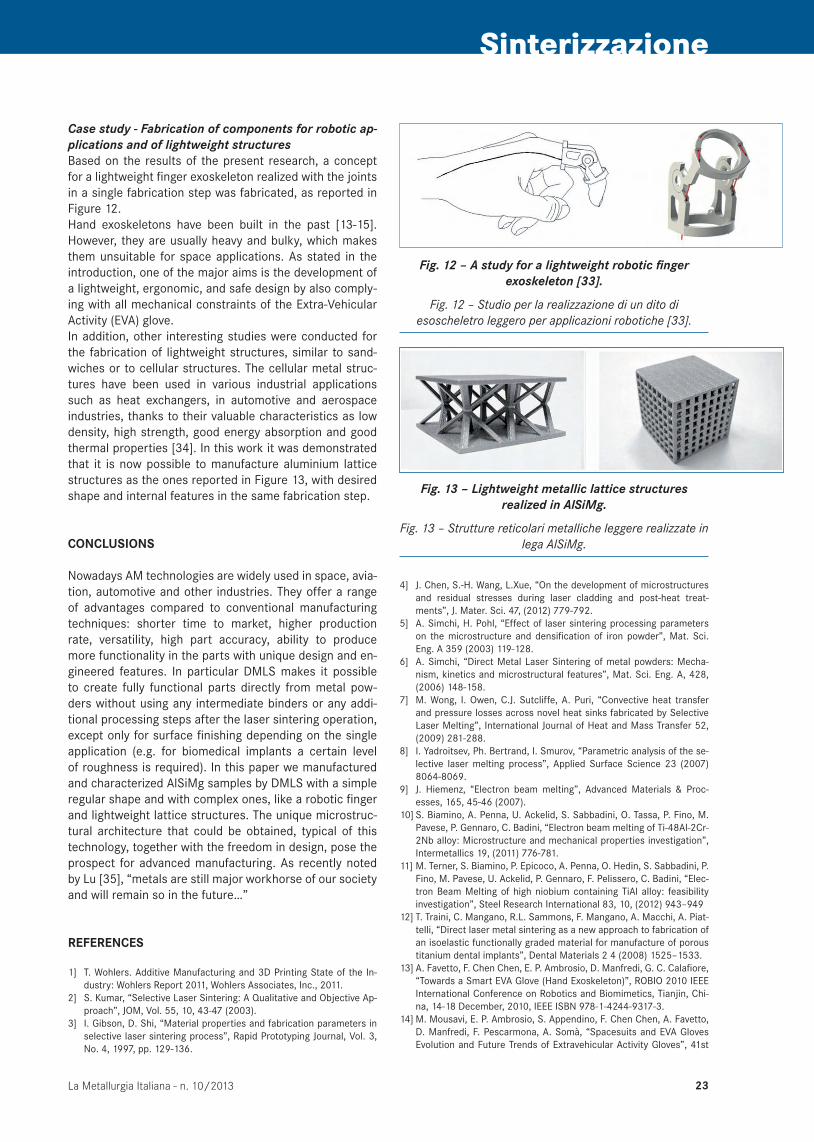
Fig. 12 – A study for a lightweight robotic finger exoskeleton [33].
Fig. 12 – Studio per la realizzazione di un dito di esoscheletro leggero per applicazioni robotiche [33].
Case study - Fabrication of components for robotic ap-plications and of lightweight structuresBased on the results of the present research, a concept for a lightweight finger exoskeleton realized with the joints in a single fabrication step was fabricated, as reported in Figure 12.Hand exoskeletons have been built in the past [13-15]. However, they are usually heavy and bulky, which makes them unsuitable for space applications. As stated in the introduction, one of the major aims is the development of a lightweight, ergonomic, and safe design by also comply-ing with all mechanical constraints of the Extra-Vehicular Activity (EVA) glove. In addition, other interesting studies were conducted for the fabrication of lightweight structures, similar to sand-wiches or to cellular structures. The cellular metal struc-tures have been used in various industrial applications such as heat exchangers, in automotive and aerospace industries, thanks to their valuable characteristics as low density, high strength, good energy absorption and good thermal properties [34]. In this work it was demonstrated that it is now possible to manufacture aluminium lattice structures as the ones reported in Figure 13, with desired shape and internal features in the same fabrication step.
CONCLUSIONS
Nowadays AM technologies are widely used in space, avia-tion, automotive and other industries. They offer a range of advantages compared to conventional manufacturing techniques: shorter time to market, higher production rate, versatility, high part accuracy, ability to produce more functionality in the parts with unique design and en-gineered features. In particular DMLS makes it possible to create fully functional parts directly from metal pow-ders without using any intermediate binders or any addi-tional processing steps after the laser sintering operation, except only for surface finishing depending on the single application (e.g. for biomedical implants a certain level of roughness is required). In this paper we manufactured and characterized AlSiMg samples by DMLS with a simple regular shape and with complex ones, like a robotic finger and lightweight lattice structures. The unique microstruc-tural architecture that could be obtained, typical of this technology, together with the freedom in design, pose the prospect for advanced manufacturing. As recently noted by Lu [35], “metals are still major workhorse of our society and will remain so in the future…”
REFERENCES
1] T. Wohlers. Additive Manufacturing and 3D Printing State of the In-dustry: Wohlers Report 2011, Wohlers Associates, Inc., 2011.
2] S. Kumar, “Selective Laser Sintering: A Qualitative and Objective Ap-proach”, JOM, Vol. 55, 10, 43-47 (2003).
3] I. Gibson, D. Shi, “Material properties and fabrication parameters in selective laser sintering process”, Rapid Prototyping Journal, Vol. 3, No. 4, 1997, pp. 129-136.
Fig. 13 – Lightweight metallic lattice structures realized in AlSiMg.
Fig. 13 – Strutture reticolari metalliche leggere realizzate in lega AlSiMg.
4] J. Chen, S.-H. Wang, L.Xue, “On the development of microstructures and residual stresses during laser cladding and post-heat treat-ments”, J. Mater. Sci. 47, (2012) 779-792.
5] A. Simchi, H. Pohl, “Effect of laser sintering processing parameters on the microstructure and densification of iron powder”, Mat. Sci. Eng. A 359 (2003) 119-128.
6] A. Simchi, “Direct Metal Laser Sintering of metal powders: Mecha-nism, kinetics and microstructural features”, Mat. Sci. Eng. A, 428, (2006) 148-158.
7] M. Wong, I. Owen, C.J. Sutcliffe, A. Puri, “Convective heat transfer and pressure losses across novel heat sinks fabricated by Selective Laser Melting”, International Journal of Heat and Mass Transfer 52, (2009) 281-288.
8] I. Yadroitsev, Ph. Bertrand, I. Smurov, “Parametric analysis of the se-lective laser melting process”, Applied Surface Science 23 (2007) 8064-8069.
9] J. Hiemenz, “Electron beam melting”, Advanced Materials & Proc-esses, 165, 45-46 (2007).
10] S. Biamino, A. Penna, U. Ackelid, S. Sabbadini, O. Tassa, P. Fino, M. Pavese, P. Gennaro, C. Badini, “Electron beam melting of Ti-48Al-2Cr-2Nb alloy: Microstructure and mechanical properties investigation”, Intermetallics 19, (2011) 776-781.
11] M. Terner, S. Biamino, P. Epicoco, A. Penna, O. Hedin, S. Sabbadini, P. Fino, M. Pavese, U. Ackelid, P. Gennaro, F. Pelissero, C. Badini, “Elec-tron Beam Melting of high niobium containing TiAl alloy: feasibility investigation”, Steel Research International 83, 10, (2012) 943–949
12] T. Traini, C. Mangano, R.L. Sammons, F. Mangano, A. Macchi, A. Piat-telli, “Direct laser metal sintering as a new approach to fabrication of an isoelastic functionally graded material for manufacture of porous titanium dental implants”, Dental Materials 2 4 (2008) 1525–1533.
13] A. Favetto, F. Chen Chen, E. P. Ambrosio, D. Manfredi, G. C. Calafiore, “Towards a Smart EVA Glove (Hand Exoskeleton)”, ROBIO 2010 IEEE International Conference on Robotics and Biomimetics, Tianjin, Chi-na, 14-18 December, 2010, IEEE ISBN 978-1-4244-9317-3.
14] M. Mousavi, E. P. Ambrosio, S. Appendino, F. Chen Chen, A. Favetto, D. Manfredi, F. Pescarmona, A. Somà, “Spacesuits and EVA Gloves Evolution and Future Trends of Extravehicular Activity Gloves”, 41st

La Metallurgia Italiana - n. 10/201324
Memorie Sinterizzazione
International Conference on Environmental Systems (ICES), Portland, Oregon, 17-21 July 2011, AIAA (American Institute of Aeronautics and Astronautics) 2011-5147.
15] S. Appendino, E. P. Ambrosio, F. Chen Chen, A. Favetto, D. Manfredi, M. Mousavi and F. Pescarmona, “Effects of EVA Glove on Hand Per-formance”, 41st International Conference on Environmental Systems (ICES), Portland, Oregon, 17-21 July 2011, AIAA (American Institute of Aeronautics and Astronautics) 2011-5085.
16] C. Badini, G.M. La Vecchia, P. Fino, T. Valente, “Forging of 2124/SiCp Composite: preliminary studies of the effect on microstructure and strength”, J. of Materials Processing Technology 116, (2001), 289-297.
17] D. Manfredi, M. Pavese, S. Biamino, A. Antonini, P. Fino, C. Badini, “Microstructure and mechanical properties of co-continuous metal/ceramic composites obtained from reactive metal penetration of commercial aluminium alloys into cordierite”, Compos. Part A Appl. S., vol. 41/5 (2010), 639-645.
18] A. Simchi, D. Godlinski, “Effect of SiC particles on the laser sintering of Al-7Si-0.3Mg alloy”, Scripta Mater. 59, (2008) 199-202.
19] S. Kumar, J.P. Kruth, “Composites by rapid prototyping technology”, Materials and Design 31, (2010) 850-856.
20] D. Manfredi, E.P. Ambrosio, F. Calignano, R. Canali, M. Krishnan, S. Biamino, M. Pavese, P. Fino, “Realization and characterization of Al-SiMg/SiC composites by Direct Metal Laser Sintering”, Proceedings of ECCM15 – 15th European Conference on Composite Materials, 24-28 June 2012, Venice, ISBN: 978-88-88785-33-2.
21] E.C. Santos, M. Shiomi, K. Osakada, T. Laoui, “Rapid manufacturing of metal components by laser forming”, Int. J. of Machine Tools & Manufacture 46 (2006), 1459–1468.
22] P. Rochus, J.-Y. Plesseria, M. Van Elsen, J.-P. Kruth, R. Carrus, T. Dor-mal, “New Applications of rapid prototyping and rapid manufacturing (RP/RM) technologies for space instrumentation”, Acta Astronautica n. 61, (2007), pp. 352-359.
23] ASM Handbook, Volume 2, Properties and Selection: Non ferrous Alloys and Special-Purpose Materials, 1990, ASM International The Materials Information Company, United States of America, ISBN 0-87170-379-3.
24] F. Calignano, D. Manfredi, E. P. Ambrosio, L. Iuliano, P. Fino, “Influ-
ence of process parameters on surface roughness of aluminum parts produced by DMLS”, Int J Adv Manuf Technol (2013) 67:2743–2751, DOI: 10.1007/s00170-012-4688-9.
25] A. Evans, G. Bruno, “Relaxation of residual stress in shot peened Udimet 720Li under high temperature isothermal fatigue”, Int J Fa-tigue 2005; 27:1530–4.
26] M. Turski, S. Clitheroe, A.D. Evans, C. Rodopoulos, “Engineering the residual stress state and microstructure of stainless steel with me-chanical surface treatments”, Appl Phys A 2010; 99:549–56.
27] L.E. Murr, S.M. Gaytan, D.A. Ramirez, E. Martinez, J.Hernandez, K.N. Amato, P.W. Shindo, F.R. Medina, R.B. Wicker, “Metal Fabrication by Additive Manufacturing Using Laser and Electron Beam Melting Tech-nologies”, J. Mater. Sci. Techn., 2012, 28(1), 1–14.
28] E. Brandl, U. Heckenberger, V. Holzinger, D. Buchbinder, “Additive manufactured AlSi10Mg samples using Selective Laser Melting (SLM) Microstructure, high cycle fatigue, and fracture behavior”, Materials and Design 34 (2012) 159-169.
29] L. Thijs, K. Kempen, J.-P. Kruth, J. V. Humbeeck, “Fine-structured alu-minium products with controllable texture by selective laser melting of pre-alloyed AlSi10Mg powder”, Acta Materialia 61 (2013), 1809–1819.
30] Matweb materials data, Web-Based Data, Matweb, UK; http://www.matweb.com/
31] Lumley R. Technical data sheets for heat treated aluminium high pres-sure die castings. CSIRO Light Metals Flagship; http://csiro.au/sci-ence/ps1f1.html
32] I. Tolosa, F. Garciandía, F. Zubiri, F. Zapirain, A. Esnaola, “Study of mechanical properties of AISI 316 stainless steel processed by selec-tive laser melting, following different manufacturing strategies”, Int. J. Adv. Manuf. Tech. 51 (2010), 639–647.
33] Patent. “Giunto articolare per esoscheletro, in particolare per ap-plicazioni aerospaziali” on behalf of Politecnico di Torino e Fondazi-one Istituto Italiano di Tecnologia. Inventors: E. Atzeni, E. Bruno, F. Calignano, D. Manfredi, E.P. Ambrosio. Date 16/10/2012, n. TO2012A000902.
34] O. Rehme, “Cellular Design for Laser Freeform Fabrication”, Cuvillier Verlag, ISBN 3869552735, Hamburg, Germany (2010).
35] L. Lu, Science, vol 328, (2010) 319.
Direct Metal Laser Sintering: una tecnologia di produzione additiva in grado di fabbricare componenti strutturali
alleggeriti per applicazioni robotiche
Parole chiave: Alluminio e leghe - Solidificazione - Caratterizzazione materiali - Prove meccaniche -Microscopia elettronica - Tecnologie
La direct metal laser sintering (DMLS) è una tecnologia di produzione additiva che consente di ottenere pezzi finiti con la forma e le dimensioni volute partendo direttamente da un file di modellazione CAD attraverso la fusione successiva di strati di polvere tramite una sorgente laser. Il suo utilizzo per la produzione di oggetti 3D rappresenta una delle strade più promettenti a livello industriale. Tale approccio, infatti, permette di estendere notevolmente la libertà di pro-gettazione e di produzione, consentendo, ad esempio, di creare un oggetto con forma desiderata e struttura interna in un’unica fase di fabbricazione. La progettazione del singolo componente può essere adattata per soddisfare le funzioni e le proprietà specifiche (fisiche, meccaniche, chimiche, biologiche, etc) utilizzando materiali diversi. In particolare in questo studio si è adoperata una macchina DMLS per la realizzazione di componenti alleggeriti in lega di alluminio per applicazioni robotiche. Si è osservato che attraverso la tecnologia DMLS non solo si riescono ad ottenere interessanti proprietà meccaniche grazie alla microstruttura estremamente fine, ma si può facilmente sviluppare e approfondire lo studio di strutture reticolari leggere. Infine si prevede di sviluppare nuovi materiali per il processo DMLS, ad esempio compositi a matrice metallica leggera, ampliando così le possibilità di applicazione di questa tecnologia in campi diver-si come lo spazio, l’aeronautica e il settore automobilistico.