MEMORANDUM REPORT ARLCB-MR-8301 7 · PDF fileAND PREFORMS FOR ROTARY FORGING WILLIAM SULLIVAN...
20
Mrtdttltl TECHNICAL LIBRARY l AD ~1 MEMORANDUM REPORT ARLCB-MR-8301 7 IMPROVED INSPECTION TECHNIQUES FOR INGOTS AND PREFORMS FOR ROTARY FORGING WILLIAM SULLIVAN VITO COLANGELO MAY 1983 US ARMY ARMAMENT RESEARCH AND DEVELOPMENT COMMAND LARGE CALIBER WEAPON SYSTEMS LABORATORY BENET WEAPONS LABORATORY WATERVL1ET N.Y. 12189 APPROVED FOR PUBLIC RELEASE; DISTRIBUTION UNLIMITED DTIC QUALTTY mSPECTBDfe
Transcript of MEMORANDUM REPORT ARLCB-MR-8301 7 · PDF fileAND PREFORMS FOR ROTARY FORGING WILLIAM SULLIVAN...
Mrtdttltl TECHNICAL LIBRARY
lAD ~1
MEMORANDUM REPORT ARLCB-MR-8301 7
IMPROVED INSPECTION TECHNIQUES FOR INGOTS
AND PREFORMS FOR ROTARY FORGING
WILLIAM SULLIVAN
VITO COLANGELO
MAY 1983
US ARMY ARMAMENT RESEARCH AND DEVELOPMENT COMMAND LARGE CALIBER WEAPON SYSTEMS LABORATORY
BENET WEAPONS LABORATORY WATERVL1ET N.Y. 12189
APPROVED FOR PUBLIC RELEASE; DISTRIBUTION UNLIMITED
DTIC QUALTTY mSPECTBDfe

DISCLAIMER
The findings in this report are not to be construed as an official
Department of the Amy position unless so designated by other author-
ized documents.
The use of trade narae(s) and/or manufacture(s) does not, consti-
tute an official indorsement or approval.
DISPOSITION
Destroy this report when it is no longer needed. Do not return it
to the originator.

SECURn Y CLASSIFICATION OF THIS PAGE fWJien Dtm t Sntand)
REPORT DOCUMENTATION PAGE READ INSTRUCTIONS BEFORE COMPLETING FORM
1. REPORT NUMBER
ARLCB-MR-83017
2. COVT ACCESSION NO. 3. RECIPIENT'S CATALOG NUMBER
4. TITLE (mtdSubUtlm)
Improved Inspection Techniques for Ingots and Preforms for Rotary Forging
5. TYPE OF REPORT ft PERIOD COVERED
Final
6. PERFORMING ORG. REPORT NUMBER
'•(TfTOm Sullivan Vito Colangelo
ft. CONTRACT OR GRANT NUMBER^*)
9. PERFORMING ORGANIZATION NAME AND ADDRESS
US Army Armament Research and Development Command Benet Weapons Laboratory, DRDAR-LCB-TL Watervliet, N.Y. 12189
10. PROGRAM ELEMENT. PROJECT, TASK AREA ft WORK UNIT NUMBERS
AMCMS No. 3297.06.8048 DA Project. PRON No. M1-8-P1890-M1-1A
11. CONTROLLING OFFICE NAME AND ADDRESS
US Army Armament Research and Development Command Large Caliber Weapon Systems Laboratory Dover, New Jersey 07801
12. REPORT DATE
May 1983 13. NUMBER OF PAGES
13 1*. MONITORING AGENCY NAME ft ADDRESS^//d/f/erant from Conlrolllng Offlca) 15. SECURITY CLASS, (ol thlm report;
UNCLASSIFIED
15e. DECLASSIFICATION/DOWNGRADING SCHEDULE
16. DISTRIBUTION STATEMENT (ot thlt Report)
Approved for public release; distribution unlimited
17. DISTRIBUTION STATEMENT (ot th» mbmtract entered in Block 30. II dlllmtant from Report)
IB. SUPPLEMENTARY NOTES
Originally submitted as an MM&T project to the U.S. Army Armament Material Readiness Command.
19. KEY WORDS (Continum on fvrmm •ide if n*cmmm*ry mnd identity by block number)
Ultrasonic Inspection ESR Ingot Inspection Non-Destructive Testing
20. ABSTRACT fContlnue on rmrarmm mUm If neceeeafy and Idmnllty by block number;
This report outlines the work conducted in developing a semi-automatic product!o inspection facility for the inspection of ingots and preforms prior to hot forging. The details of the system including descriptions, procedures and drawings are available as a Technical Date Package from Watervliet Arsenal, Watervliet, N. Y.
1
DD ,: FORM AM 73 1473 EOrTIOH OF t MOV •» IS OBSOLETE UNCLASSIFIED
SECURITY CLASSIFICATION OF THIS PAGE fWheo Defe Enlfd)

TABLE CF GONTENTS
Page
1
1
INTRODUCTION
BACKGROUND
Approach and Objective 3
CONCUJSION 8
ILLUSTRATIONS
Figure
1. Placing the Reflectors with Respect to the Director of the Ultrasonic Beam 9
■ 2. C.R.T. Display showing the Initial Pulse Echoes and Badcwall Reflectors 10
3. Test System to Evaluate Ultrasonic Transmissions Capabilities under Actual Conditions 11
4. Sketch of Automatic Scanning Systan 12
INTRODUCTION
A nondestructive test to insure the internal soundness
of an ingot or preform is required prior to rotary forging.
Ultrasonic scanning by means of a hand-held transducer was the
initial nondestructive approach. However, this method is very
time consuming and prone to ooerator fatigue and error. The
time required to completely inspect all of the material was
extensive enough to impede the rotary forge process. As a
consequence, only a percentage of the ingots and preforms
were tested. In order to inspect all of the material while
maintaining the production schedules, the design of an auto-
matic ultrasonic NOT system was established.
BACKGROUND
Two matters of grave concern that were encountered in
the engineering phases of the oroject were the sonic transfer
capabilities due to the surface condition of the ingots and
preforms and the internal grain structure of the ingots. The
state of the art for this tyoe of inspection has been estab-
lished with regard to feasibility. However, each installation
requires a different engineering approach. Flaw dimensions,
search frequency and the sonic transfer medium were determined
in-house and were given to outside contractors for evaluation
tests.
The flaw dimensions inspection standard definitions are
referenced and taken from the Metals Handbook Nondestructive
Inspection and Quality Control, Volume II, Pages 187, 188 and 189,
1

published by the American Society for Metals. The ultrasonic
test criteria have been established by the American Society
of Nondestructive,Testing and the American Society for Testing
Material. Examples of defect sizes are as follows: a number 1
defect is a flat bottom hole 1/64" in diameter, and a number
2 defect is a flat bottom hole 2/64" in diameter. These in-
dicators are drilled into different size test blocks.
The internal structure of the ingots and the surface
variations of all the material to be tested supplanted the
use of test blocks. The desired reflectors were placed into
the center of the test material. The test material was four
inch discs of ingots and preforms. Figure 1 is a diagram
showing how the reflectors are placed in the center of the
test pieces. A detailed explanation of the reflectors and
material conditions is presented in the approach to the
problem section of this report.
The type of material, the couplant and surface conditions
are all of the parameters that have to be taken into con-
sideration to determine the search frequency. This frequency
will also establish the smallest size defect that can be
detected. The frequency established for this project was
2.25 MHz in the longitudinal mode.
The following ultrasonic sizes were established and in-
corporated into the data presented to contractors for the
evaluation test.

The ultrasonic instrument and the associated equipment
shall be capable of detecting a #5 size defect at the center
of a 20" diameter ESR melted ingot and a #4 defect size at
the center of a 15" diameter and a 13" diameter preform.
The following vendors were contracted to oerform the
evaluation test:
Sonics Instruments, Inc. 1018 White Head Road Trenton, New Jersey
Krautkramer-Branson, Inc. 250 Long Beach Blvd. Stratford, Conn.
Automation Industries Sperry Products Division Shelter Rock Road Danbury, Conn.
All three contractors declared that they are capable of
detecting the determined flaw and/or reflector dimensions.
A 1095 form for the procurement of the Ultrasonic system
was sent to the Purchasing and Contracting Division at the
Watervliet Arsenal on 13 March 1980.
Automation Industries, Sperry Division, was awarded the
contract to design the scanning System and to provide the
ultrasonic instrumentation and search transducer as called
for in the specification.
Approach and Objective
As previously stated, the surface condition of the ingots
and preforms and the internal structure of the ESR ingots pre-
sented engineering difficulties that were specific to this
type of nondestructive automatic ultrasonic scanning application

The surfaces of the ESR ingots are slightly convoluted;
this is a condition that is inherent to the ESR process. The
surface of the preforms contain many facets and indentures;
these are caused by the hammer blows encountered during the
rotary forge process. The unevenness of the surfaces results
in a non-uniform transfer of the ultrasonic energy to and from
the search transducer and the workoiece.
The surface variations, couplant medium for the sonic
energy transfer, internal structure of the material and the
scanning method all have to be considered in order to design
a workable system.
It was decided that the couplant medium shall be water.
Oil was eliminated because it created smut problems in the
heating furnaces that are part of the rotary forge heat
treating production line.
In order to compensate for the surface conditions, a
method of overlap scanning was designed. The scanning system
is comprised of a circumferential scan with longitudinal in-
dexing. The numerical readout from the starting point along
the longitudinal axis will be adjustable to within one-half
inch along the axis. Each circumferential scan will have
an overlaoping coverage of the oreceding scan. With this
form of indexing, every part or section of the ingot or
preform will be investigated. This method of overlapping
will establish the capability to institute programming defect
repeatabi1ity.
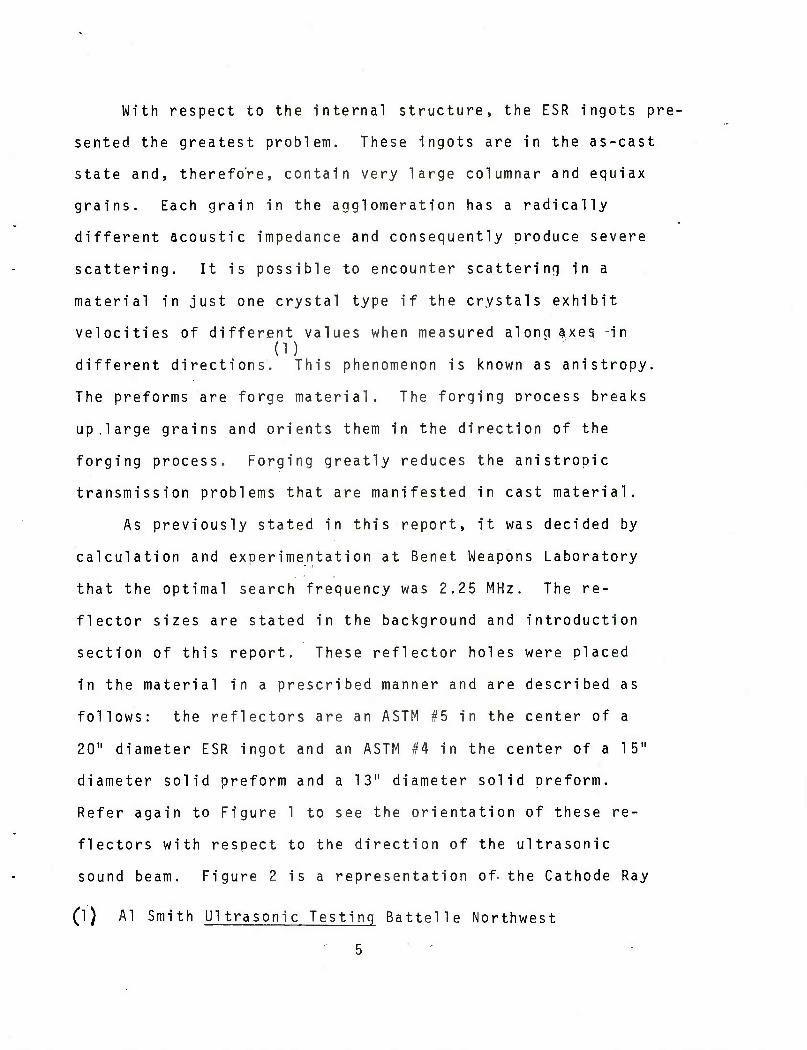
With respect to the internal structure, the ESR ingots pre-
sented, the greatest problem. These ingots are in the as-cast
state and, therefore, contain very large columnar and equiax
grains. Each grain in the agglomeration has a radically
different acoustic impedance and consequently produce severe
scattering. It is possible to encounter scattering in a
material in just one crystal type if the crystals exhibit
velocities of different values when measured along axes -in (D
different directions. This phenomenon is known as anistropy.
The preforms are forge material. The forging process breaks
up,large grains and orients them in the direction of the
forging process. Forging greatly reduces the anistrooic
transmission problems that are manifested in cast material.
As previously stated in this report, it was decided by
calculation and exoerimentation at Benet Weapons Laboratory
that the optimal search frequency was 2.25 MHz. The re-
flector sizes are stated in the background and introduction
section of this report. These reflector holes were placed
in the material in a prescribed manner and are described as
follows: the reflectors are an ASTM #5 in the center of a
20" diameter ESR ingot and an ASTM #4 in the center of a 15"
diameter solid preform and a 13" diameter solid preform.
Refer again to Figure 1 to see the orientation of these re-
flectors with respect to the direction of the ultrasonic
sound beam. Figure 2 is a representation of- the Cathode Ray
(l) Al Smith Ultrasonic Testing Battelle Northwest
5 '

Tube display showing the initial pulse, echoes and backwall re-
flections. Figure 3 shows photographs of an experimental set-
up of an immersion system.
Immersion testing was chosen because it is preferable to
contact testing for forging and casting that have irregular
surfaces. This type of part cannot be comoletely inspected
by the contact method by any practical means.
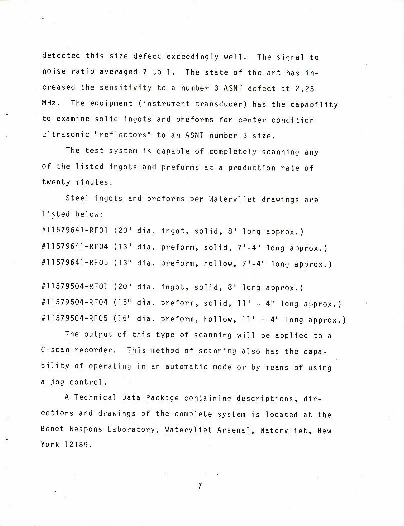
RESULTS
The Benet Weapons Laboratory received the design drawings
and instrumentation for a complete automatic ultrasonic non-
destructive system to test ingots and preforms prior to the
rotary forge process. (Figure 4 is a sketch of the test
system).
The sensitivity for defect sizes exceeded that required
by the specifications. This was accomplished by the use of
a focused immersion transducer (2.25 MHz) (1 x 1/2 resolution)
(Harrisonic 18A0208161) (Sperry #77A336). The ultrasonics
utilize the Pulse-Echo Method and the energy transfer is
accomplished by a couplant-column dispenser/chamber arrange-
ment using water as the sonic transfer medium. The size of
the defect at the center of a 20" diameter ESR ingot under
actual conditions was a number 2 (3/64" diameter) longitudinally
oriented flat bottom hole perpendicular to the longitudinal
center line. The instrument is a Sperry Model S-80 Reflecto-
scope. The instrument and the integrated components used
detected this size defect exceedingly well. The signal to
noise ratio averaged 7 to 1. The state of the art has in-
creased the sensitivity to a number 3 ASNT defect at 2.25
MHz. The equipment (instrument transducer) has the capability
to examine solid ingots and preforms for center condition
ultrasonic "reflectors" to an ASNT number 3 size.
The test system is capable of completely scanning any
of the listed ingots and preforms at a production rate of
twenty minutes.
Steel ingots and preforms per Watervliet drawings are
1isted below:
#11579641-RF01 (20" dia. ingot, solid, 8J long approx.)
#11579641-RF04 (13" dia. preform, solid, 7,-4" long approx.)
#11579641-RF05 (13" dia. preform, hollow, 7,-4" long approx.)
#11579504-RF01 (20" dia. ingot, solid, 81 long approx.)
#11579504-RF04 (15" dia. preform, solid, 11' - 4" long approx.)
#11579504-RF05 (15" dia. preform, hollow, 11' - 4" long approx.)
The output of this type of scanning will be applied to a
C-scan recorder. This method of scanning also has the capa-
bility of operating in an automatic mode or by means of using
a jog control.
A Technical Data Package containing descriptions, dir-
ections and drawings of the complete system is located at the
Benet Weapons Laboratory, Watervliet Arsenal, Watervliet, New
York 12189.

CONCLUSION
The increased sensitivity of ultrasonics and the use of
focused ultrasonic beams has rendered this apolication of
nondestructive testing from the prototype status to a functional
unit in the rotary forge production line.
The developed technique will also be capable of being
utilized by the preform producers, thereby enabling them to
relate production practice to quality and soundness. This
should result in an overall increase in the quality of in-
coming material.

TO THE ULTRASONIC EQUIPMENT
TEST SHOULD BE CONDUCTED IN THIS AREA FOR MAXIMUM RESULTS
SOUND ENERGY-
NOTE THIS SURFACE SHOULD BE PARALLEL TO THE TANK BOTTOM
TRANSDUCER (HARRISONIC PART NO. I8A0208I6T)
WATER PATH
TEST PIECE SECTOR OF A 20" DIAMETER INGOT OR A IS'; ^"DIAMETER PREFORM
5ASNT
FIGURE I

STANDARD CRT DISPLAY FOR IMMERSION TESTING
INITIAL PULSE
THE CRT IS ON THE ULTRASONIC INSTRUMENT
♦WATER- PATH
FIRST WTERFACE ECHO
DEFECT REFLECTED
ECHO
BACK WALL ECHO
WATER PATH IS NORMALLY NOT SHOWN IN IMMERSION
TESTING. THE USABLE AREA IS BETWEEN
INTERFACE ECHO AND BACK WALL ECHO
FIGURE 2 10

FIG. 3 - Test System to evaluate ultra- sonic transmission capabilities under actual conditions. Disc from a 20"dia. ESR ingot. 11


TECHNICAL REPORT INTERNAL DISTRIBUTION LIST
CHIEF, DEVELOPMENT ENGINEERING BRANCH ATTN: DRDAR-LCB-D
-DP -DR -DS (SYSTEMS) -DS (ICAS GROUP) -DC
CHIEF, ENGINEERING SUPPORT BRANCH ATTN: DRDAR-LCB-S
-SE
CHIEF, RESEARCH BRANCH ATTN: DRDAR-LCB-R
-R (ELLEN FOGARTY) -RA -RM -RP -RT
TECHNICAL LIBRARY ATTN: DRDAR-LCB-TL
TECHNICAL PUBLICATIONS & EDITING UNIT ATTN: DRDAR-LCB-TL
DIRECTOR, OPERATIONS DIRECTORATE
DIRECTOR, PROCUREMENT DIRECTORATE
DIRECTOR, PRODUCT ASSURANCE DIRECTORATE
NO. OF COPIES
1 1 1 1 1 1
2 1 1 1 1 1
NOTE: PLEASE NOTIFY DIRECTOR, BENET WEAPONS LABORATORY, ATTN: DRDAR-LCB-TL, OF ANY REQUIRED CHANGES.

TECHNICAL REPORT EXTERNAL DISTRIBUTION LIST
NO. OF COPIES
NO. OF COPIES
ASST SEC OF THE ARMY RESEARCH £ DEVELOPMENT ATTN: DEP FOR SCI § TECH THE PENTAGON WASHINGTON, D.C. 20315
COMMANDER DEFENSE TECHNICAL INFO CENTER ATTN: DTIC-DDA CAMERON STATION ALEXANDRIA, VA 22314
COMMANDER US ARMY MAT DEV § READ COMD ATTN: DRCDE-SG 5001 EISENHOWER AVE ALEXANDRIA, VA 22333
COMANDER US ARMY ARRADCOM ATTN: DRDAR-LC
DRDAR-LCA (PLASTICS TECH EVAL CEN)
DRDAR-LCE DRDAR-LCM (BLDG 321) DRDAR-LCS DRDAR-LCU DRDAR-LCW DRDAR-TSS (STINFO)
DOVER, NJ 07801
DIRECTOR US ARMY BALLISTIC RESEARCH LABORATORY ATTN: DRDAR-TSB-S (STINFO) ABERDEEN PROVING GROUND, MD 21005
COMMANDER US ARMY ARRCOM ATTN: DRSAR-LEP-L ROCK ISLAND ARSENAL ROCK ISLAND, IL 61299
12
1 1
1 1 1 1 1 2
COMMANDER ROCK ISLAND ARSENAL ATTN: SARRI-ENM (MAT SCI DIV) ROCK ISLAND, IL 61299
DIRECTOR US ARMY INDUSTRIAL BASE ENG ACT ATTN: DRXIB-M ROCK ISLAND, IL 61299
COMMANDER US ARMY TANK-AUTMV RfiD COMD ATTN: TECH LIB - DRSTA-TSL WARREN, MICHIGAN 48090
COMMANDER US ARMY TANK-AUTMV COMD ATTN: DRSTA-RC WARREN, MICHIGAN 48090
COMMANDER US MILITARY ACADEMY ATTN: CHMN, MECH ENGR DEPT WEST POINT, NY 10996
US ARMY MISSILE COMD REDSTONE SCIENTIFIC INFO CEN ATTN: DOCUMENTS SECT, BLDG 4484 REDSTONE ARSENAL, AL 35898
COMMANDER US ARMY FGN SCIENCE ATTN: DRXST-SD 220 7TH STREET, N.E. CHARLOTTESVILLE, VA
§ TECH CEN
22901
COMMANDER US ARMY MATERIALS § MECHANICS
RESEARCH CENTER ATTN: TECH LIB - DRXMR-PL WATERTOWN, MASS 02172
NOTE: PLEASE NOTIFY COMMANDER, ARRADCOM, ATTN: BENET WEAPONS LABORATORY DRDAR-LCB-TL, WATERVLIET ARSENAL, WATERVLIET, N.Y. 12189, OF ANY REQUIRED CHANGES.

TECHNICAL REPORT EXTERNAL DISTRIBUTION LIST (CONT.)
NO. OF COPIES
COMMANDER US ARMY RESEARCH OFFICE ATTN: CHIEF, IPO P.O. BOX 12211 RESEARCH TRIANGLE PARK, NC
COMMANDER US ARMY HARRY DIAMOND LAB ATTN: TECH LIB 2800 POWDER MILL ROAD ADELPHIA, MD 20783
COMMANDER NAVAL SURFACE WEAPONS CEN ATTN: TECHNICAL LIBRARY
CODE X212 DAHLGREN, VA 22448
27709
DIRECTOR US NAVAL RESEARCH LAB ATTN: DIR, MECH DIV
CODE 26-27 (DOC LIB) WASHINGTON, D.C. 20375
METALS § CERAMICS INFO CEN BATTELLE COLUMBUS LAB 505 KING AVE COLUMBUS, OHIO 43201
MATERIEL SYSTEMS ANALYSIS ACTV ATTN: DRSXY-MP ABERDEEN PROVING GROUND MARYLAND 21005
NO. OF COPIES
NOTE: PLEASE NOTIFY COMMANDER, ARRADCOM, ATTN: BENET WEAPONS LABORATORY, DRDAR-LCB-TL, WATERVLIET ARSENAL, WATERVLIET, N.Y. 12189, OF ANY REQUIRED CHANGES.

READER EVALUATION
Please take a few minutes to complete the questionnaire below and return to us at the following address: Commander, U.S. Army ARRADCOM, ATTN: Technical Publications, DRDAR-LCB-TL, Watervliet, New York 12189.
1. Benet Weapons Lab. Report Number
2. Please evaluate this publication (check off one or more as applicable).
Yes No Information Relevant Information Technically Satisfactory Format Easy to Use Overall, Useful to My Work Other Comments
3. Has the report helped you in your own areas of interest? (i.e. preventing duplication of effort in the same or related fields, savings of time, or money),
4. How is the report being used? (Source of ideas for new or Improved designs. Latest information on current state of the art, etc.).
5. How do you think this type of report could be changed or revised to improve readability, usability?
6. Vfould you like to communicate directly with the author of the report regarding subject matter or topics not covered in the report? If so please fill in the following information.
Name
Telephone Number:
Organization Address;