MEMOCODE 2007 HW/SW Co-design Contest
57
MEMOCODE 2007 HW/SW Co-design Contest Documentation of the submission by Eric Simpson Pengyuan Yu Sumit Ahuja Sandeep Shukla Patrick Schaumont Electrical and Computer Engineering Department Virginia Tech
description
MEMOCODE 2007 HW/SW Co-design Contest. Documentation of the submission by. Eric Simpson Pengyuan Yu Sumit Ahuja Sandeep Shukla Patrick Schaumont. Electrical and Computer Engineering Department Virginia Tech. Table of Contents. Section 1 Performance Evaluation and Analysis - PowerPoint PPT Presentation
Transcript of MEMOCODE 2007 HW/SW Co-design Contest
MEMOCODE 2007HW/SW Co-design Contest
Documentation of the submission by
Eric SimpsonPengyuan YuSumit AhujaSandeep ShuklaPatrick Schaumont
Electrical and Computer Engineering
DepartmentVirginia Tech

Table of Contents
Section 1 Performance Evaluation and Analysis Section 2 Matrix Multiplication Algorithm Optimization Section 3 HW/SW System Implementation Section 4 Co-design Flow and Methodology Section 5 Conclusion

Section 1Performance Evaluation and
Analysis

Performance Results
Section 1 Performance Evaluation and Analysis
Matrix Size 64 128 256 512 1024
Run Time(sec)
Our Design
(Average)0.0052 0.0322 0.2170 1.5176 11.882
Reference 0.0346 0.6697 5.3133 42.302 338.72
SpeedUp 6.65 20.8 24.5 26.9 28.5
DeviceUtilization
BRAM 80 (64 Coprocessor + 16 On-Chip-Memory)
Mult 128

Performance Calculation
FCPU-Speed = 1, we used 300Mhz PPC FFPGA-Capacity = 1, we used XUP’s XC2VP30 FFPGA-speed = 1, we used 100Mhz clock for bus and
coprocessor
TimeEffective = (Tmeas,N=1024 + Tmeas,N=256 * 64) *
FCPU-Speed * FFPGA-Capacity * FFPGA-speed
= (11.882 + 64*0.217) * 1 * 1 * 1 = 25.77 seconds
Section 1 Performance Evaluation and Analysis

Performance Results
Section 1 Performance Evaluation and Analysis
Speed Up Factor Against Reference Design (Blocked by 16)
6.66
20.79
24.4926.92
28.51
0.00
5.00
10.00
15.00
20.00
25.00
30.00
64 128 256 512 1,024
Test Case Matrix Size
Spee
dUp
Fact
or

Section 2Matrix Multiplication
Algorithm Optimization

Algorithm Optimization
Algorithm is optimized based on targeting platform (Virtex2 Pro VP30)
Optimization goal: Best utilized the slow DDR Memory Interface
Optimally 128-bit/cycle transfers => 4 Complex Numbers Linear accesses result in better throughput
Utilize as many fast discrete FPGA Resources as possible 136 18x18-Hardware Multipliers 136 18kbits Block Rams
Section 2 Matrix Multiplication Algorithm Optimization

• [A] currently in coprocessor
• [A] currently used for calculation
• [B] currently used for calculation
• [C] stored and accumulated in BRAM
• [C] being multiplied and accumulated
Optimized Algorithm
A
B
Section 2 Matrix Multiplication Algorithm Optimization
C

Optimized Algorithm
A
B
C
Bring in 4 complex numbers from “A”
• [A] currently in coprocessor
• [A] currently used for calculation
• [B] currently used for calculation
• [C] stored and accumulated in BRAM
• [C] being multiplied and accumulated
Section 2 Matrix Multiplication Algorithm Optimization
C

Optimized Algorithm
A
B
C
• [A] currently in coprocessor
• [A] currently used for calculation
• [B] currently used for calculation
• [C] stored and accumulated in BRAM
• [C] being multiplied and accumulated
Section 2 Matrix Multiplication Algorithm Optimization
C

Optimized Algorithm
A
B
C
• [A] currently in coprocessor
• [A] currently used for calculation
• [B] currently used for calculation
• [C] stored and accumulated in BRAM
• [C] being multiplied and accumulated
Section 2 Matrix Multiplication Algorithm Optimization
C

Optimized Algorithm
A
B
C
• [A] currently in coprocessor
• [A] currently used for calculation
• [B] currently used for calculation
• [C] stored and accumulated in BRAM
• [C] being multiplied and accumulated
Section 2 Matrix Multiplication Algorithm Optimization
C

Optimized Algorithm
A
B
C
• [A] currently in coprocessor
• [A] currently used for calculation
• [B] currently used for calculation
• [C] stored and accumulated in BRAM
• [C] being multiplied and accumulated
Section 2 Matrix Multiplication Algorithm Optimization
C

Optimized Algorithm
A
B
C
• [A] currently in coprocessor
• [A] currently used for calculation
• [B] currently used for calculation
• [C] stored and accumulated in BRAM
• [C] being multiplied and accumulated
Section 2 Matrix Multiplication Algorithm Optimization
C
• Bring in four numbers from “B” and perform the following calculations:
C[0][0] = C[0][0] + A[0][0]*B[0][0]C[0][1] = C[0][0] + A[0][0]*B[0][1]C[0][2] = C[0][0] + A[0][0]*B[0][2]C[0][3] = C[0][0] + A[0][0]*B[0][3]…C[8][0] = C[8][0] + A[8][0]*B[0][0]C[8][1] = C[8][0] + A[8][0]*B[0][1]C[8][2] = C[8][0] + A[8][0]*B[0][2]C[8][3] = C[8][0] + A[8][0]*B[0][3]
• Where “A*B” is a complex multiplication.
• 32 Complex multiplication in parallel = 128 multiplies, 64 additions/subtractions and 64 accumulates per cycle

Optimized Algorithm
A
B
C
• [A] currently in coprocessor
• [A] currently used for calculation
• [B] currently used for calculation
• [C] stored and accumulated in BRAM
• [C] being multiplied and accumulated
Section 2 Matrix Multiplication Algorithm Optimization
C

Optimized Algorithm
A
B
C
• [A] currently in coprocessor
• [A] currently used for calculation
• [B] currently used for calculation
• [C] stored and accumulated in BRAM
• [C] being multiplied and accumulated
Section 2 Matrix Multiplication Algorithm Optimization
C

Optimized Algorithm
A
B
C
• [A] currently in coprocessor
• [A] currently used for calculation
• [B] currently used for calculation
• [C] stored and accumulated in BRAM
• [C] being multiplied and accumulated
Section 2 Matrix Multiplication Algorithm Optimization
C

Optimized Algorithm
A
B
C
• [A] currently in coprocessor
• [A] currently used for calculation
• [B] currently used for calculation
• [C] stored and accumulated in BRAM
• [C] being multiplied and accumulated
Section 2 Matrix Multiplication Algorithm Optimization
C

Optimized Algorithm
A
B
C
• [A] currently in coprocessor
• [A] currently used for calculation
• [B] currently used for calculation
• [C] stored and accumulated in BRAM
• [C] being multiplied and accumulated
Section 2 Matrix Multiplication Algorithm Optimization
C

Optimized Algorithm
A
B
C
• [A] currently in coprocessor
• [A] currently used for calculation
• [B] currently used for calculation
• [C] stored and accumulated in BRAM
• [C] being multiplied and accumulated
Section 2 Matrix Multiplication Algorithm Optimization
C

Optimized Algorithm
A
B
C
• [A] currently in coprocessor
• [A] currently used for calculation
• [B] currently used for calculation
• [C] stored and accumulated in BRAM
• [C] being multiplied and accumulated
Section 2 Matrix Multiplication Algorithm Optimization
C

Optimized Algorithm
A
B
C
• [A] currently in coprocessor
• [A] currently used for calculation
• [B] currently used for calculation
• [C] stored and accumulated in BRAM
• [C] being multiplied and accumulated
Section 2 Matrix Multiplication Algorithm Optimization
C

Optimized Algorithm
A
B
C
• [A] currently in coprocessor
• [A] currently used for calculation
• [B] currently used for calculation
• [C] stored and accumulated in BRAM
• [C] being multiplied and accumulated
Section 2 Matrix Multiplication Algorithm Optimization
C

Optimized Algorithm
A
B
C
• [A] currently in coprocessor
• [A] currently used for calculation
• [B] currently used for calculation
• [C] stored and accumulated in BRAM
• [C] being multiplied and accumulated
Section 2 Matrix Multiplication Algorithm Optimization
C

Optimized Algorithm
A
B
C
• [A] currently in coprocessor
• [A] currently used for calculation
• [B] currently used for calculation
• [C] stored and accumulated in BRAM
• [C] being multiplied and accumulated
Section 2 Matrix Multiplication Algorithm Optimization
C

Optimized Algorithm
A
B
C
• [A] currently in coprocessor
• [A] currently used for calculation
• [B] currently used for calculation
• [C] stored and accumulated in BRAM
• [C] being multiplied and accumulated
Section 2 Matrix Multiplication Algorithm Optimization
C

Optimized Algorithm
A
B
C
• [A] currently in coprocessor
• [A] currently used for calculation
• [B] currently used for calculation
• [C] stored and accumulated in BRAM
• [C] being multiplied and accumulated
Section 2 Matrix Multiplication Algorithm Optimization
C

Optimized Algorithm
A
B
C
• [A] currently in coprocessor
• [A] currently used for calculation
• [B] currently used for calculation
• [C] stored and accumulated in BRAM
• [C] being multiplied and accumulated
Section 2 Matrix Multiplication Algorithm Optimization
C

Optimized Algorithm
A
B
C
• [A] currently in coprocessor
• [A] currently used for calculation
• [B] currently used for calculation
• [C] stored and accumulated in BRAM
• [C] being multiplied and accumulated
Section 2 Matrix Multiplication Algorithm Optimization
C

Optimized Algorithm
A
B
C
• [A] currently in coprocessor
• [A] currently used for calculation
• [B] currently used for calculation
• [C] stored and accumulated in BRAM
• [C] being multiplied and accumulated
Section 2 Matrix Multiplication Algorithm Optimization
C

Optimized Algorithm
A
B
C
• [A] currently in coprocessor
• [A] currently used for calculation
• [B] currently used for calculation
• [C] stored and accumulated in BRAM
• [C] being multiplied and accumulated
Section 2 Matrix Multiplication Algorithm Optimization
C

Optimized Algorithm
A
B
C
• [A] currently in coprocessor
• [A] currently used for calculation
• [B] currently used for calculation
• [C] stored and accumulated in BRAM
• [C] being multiplied and accumulated
Section 2 Matrix Multiplication Algorithm Optimization
C

Optimized Algorithm
A
B
C
• [A] currently in coprocessor
• [A] currently used for calculation
• [B] currently used for calculation
• [C] stored and accumulated in BRAM
• [C] being multiplied and accumulated
Section 2 Matrix Multiplication Algorithm Optimization
C

Optimized Algorithm
A
B
C
• [A] currently in coprocessor
• [A] currently used for calculation
• [B] currently used for calculation
• [C] stored and accumulated in BRAM
• [C] being multiplied and accumulated
Section 2 Matrix Multiplication Algorithm Optimization
C

Optimized Algorithm
A
B
C
• [A] currently in coprocessor
• [A] currently used for calculation
• [B] currently used for calculation
• [C] stored and accumulated in BRAM
• [C] being multiplied and accumulated
Section 2 Matrix Multiplication Algorithm Optimization
C
At this point we have completed calculating the first 8xN rows of C in our coprocessor and we write the results back to RAM

Optimized Algorithm
A
B
C
• [A] currently in coprocessor
• [A] currently used for calculation
• [B] currently used for calculation
• [C] stored and accumulated in BRAM
• [C] being multiplied and accumulated
Section 2 Matrix Multiplication Algorithm Optimization
C

Optimized Algorithm
A
B
C
• [A] currently in coprocessor
• [A] currently used for calculation
• [B] currently used for calculation
• [C] stored and accumulated in BRAM
• [C] being multiplied and accumulated
Section 2 Matrix Multiplication Algorithm Optimization
Next, we repeat the previous algorithm to
calculate the next “8xN CSlice”

Optimized Algorithm
Performs 128 MACs per cycle (utilizing 128 out of 136 hard multipliers)
Linear scan through B matrix (optimizing interface to DDR storage)
Section 2 Matrix Multiplication Algorithm Optimization

Section 3HW/SW System Implementation

System Architecture
Processor Local Bus
Section 3 HW/SW System Implementation

Minor deviation from proposed algorithm I/O size for coprocessor: B elements are loaded 2
at a time instead of 4 PLB DMA failed to function resulting in a much slower
{DDR->PPC->Coprocessor FIFO} datapath. FIFO width of 64-bit => 2-number sends from PPC to
Coprocessor FIFO To maintain SAME calculation capacity: A-Block
dimension doubled from 8x4 to 16x4. C-Slice doubled from 8xN to 16xN Still utilizes 128 Hardware Multipliers.
Coprocessor Architecture vs. Optimized Algorithm
Section 3 HW/SW System Implementation

Coprocessor Architecture
Coprocessor is scalable! Reduce the depth of the A-matrix subblock to
reduce the amount of MAC needed
Section 3 HW/SW System Implementation

Coprocessor Architecture
Section 3 HW/SW System Implementation

MAC Unit ArchitectureB(0,0) B(0,1)
A(0,0)
C(0,1)
X
C(0,0)
X
A(L,0)
C(L,1)
X
C(L,0)
X
......
...
Row[0]
Row[15]
Section 3 HW/SW System Implementation
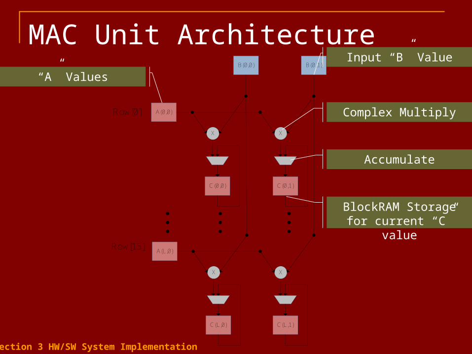
MAC Unit ArchitectureB(0,0) B(0,1)
A(0,0)
C(0,1)
X
C(0,0)
X
A(L,0)
C(L,1)
X
C(L,0)
X
......
...
Row[0]
Row[15]
Complex Multiply
Accumulate
BlockRAM Storage for current “C” value
Input “B” Value
“A” Values
Section 3 HW/SW System Implementation

Section 4Co-design Flow and
Methodology

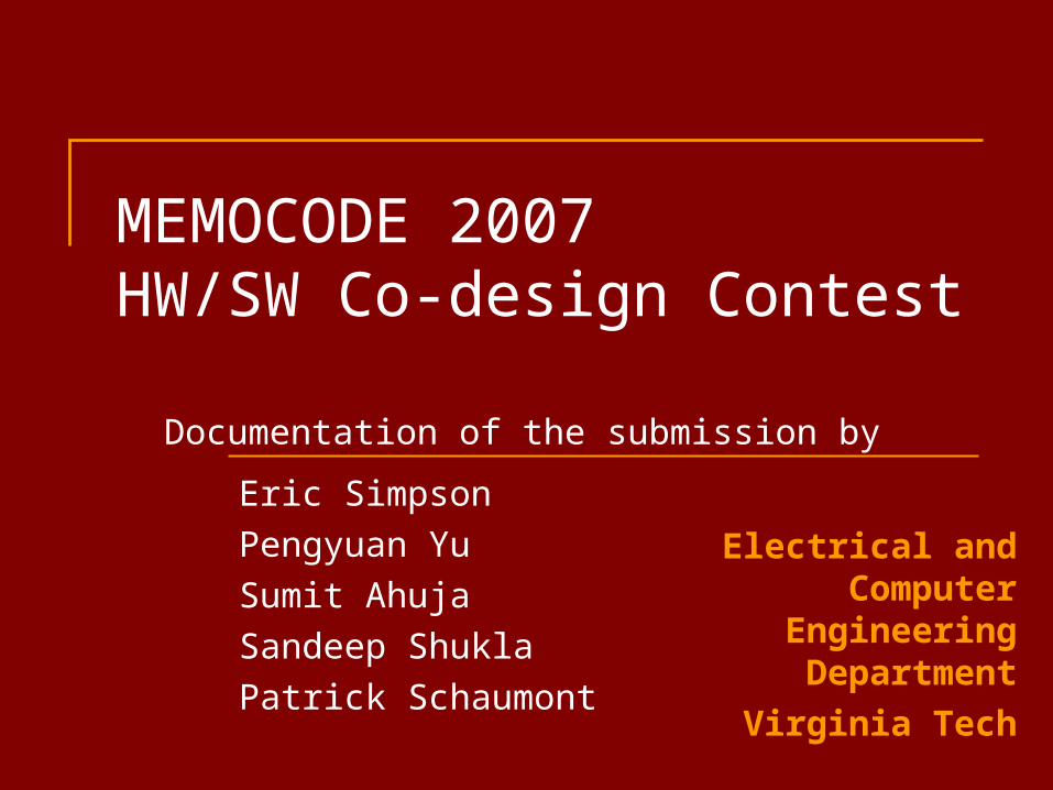
Design Flow ReferenceC Algorithm
OptimizedC Algorithm
Driver CAlgorithm
GEZELCoprocessor
VHDLPPC Binary
XUP Board
Manual Partitioning
Rectangular-BlockTransformation
Cosimulation
Synthesis
PerformanceAnalysis
Section 4 Co-design Flow and Methodology

Simulation ReferenceC Algorithm
OptimizedC Algorithm
Driver CAlgorithm
GEZELCoprocessor
VHDLPPC Binary
XUP Board
workstation
cycle-basedinstruction-set
cosimulator
FPGA
Section 4 Co-design Flow and Methodology

Simulation Simulation-based verification on three levels
workstation (behavioral) cycle-based ISS (functional model of coprocessor) FPGA board (skipping VHDL simulation since
synthesis is swift and easy) Drawback - simulations capture only behavior,
but not the architecture. Example: Hard to estimate post-synthesis timing Example: Hard to reflect memory-bus behavior (DMA,
DDR, ...) in a C simulation model
Section 4 Co-design Flow and Methodology

Cycle-based Instruction-set Simulation Uses GEZEL Cosimulation Tool
http://rijndael.ece.vt.edu/gezel2
Application SW(C Code)
uP DDR
“N” Reg FIFO IN FIFO OUT
Coprocessor
ExecutableInstruction
Set simulator
CosimulationInterfaces
CoprocessorHardware
Section 4 Co-design Flow and Methodology

Cycle-based Instruction-set Simulation Need cycle-based cosimulation of software
and hardware before synthesis Coprocessor mapped in FSMD semantics
Modular bottom-up hardware description Cosimulation Interfaces captured with GEZEL
simulation primitives Memory-mapped register FIFO based (with request/acknowledge
handshake)
Section 4 Co-design Flow and Methodology

HW-SW Interface Example
ipblock fsl1(out data : ns(32); out exists : ns(1); in read : ns(1)) { iptype "armfslslave"; ipparm "core=ppc"; ipparm "write=0x80000000"; ipparm "status=0x80000004"; } to
cop
roce
ssor
data
exists
read
connectedto ISS
PPC SW can write to address 0x80000000 Will drive data output and perform handshake
PPC SW can check status with read from 0x80000004
fsl1
GEZEL Code Hardware
Section 4 Co-design Flow and Methodology

SynthesisApplication SW
(C Code)
uP DDR
“N” Reg FIFO IN FIFO OUT
Coprocessor
InstructionSet simulator
CosimulationInterfaces
CoprocessorHardware
Automatic conversion to hierarchical RTL-VHDL, withblack-boxes for cosimulation
interfacesXilinx EDK + ISE
Section 4 Co-design Flow and Methodology

Conclusions
Matrix Multiplication can be sped up by 25 times over standard reference C implementation Rectangular Blocking Dedicated Coprocessor Hardware, highly scalable Integrated design flow

Conclusions
Remaining Challenges Memory bottleneck (hardware/software codesign
yields ~7 % computation time and 93 % memory access time) Further optimization possible using DMA and data
caching schemes

Conclusions
Challenge to the MEMOCODE community accurate system-level modeling of platform artifacts to
support the designer