Membrane-Based Self-Powered … · Peng Bai , Guang Zhu , Qingshen Jing , Jin ang , Y Jun Chen ,...
7
FULL PAPER © 2014 WILEY-VCH Verlag GmbH & Co. KGaA, Weinheim 5807 wileyonlinelibrary.com such as recently emerged triboelectric sensors. [12–14] Triboelectric sensors take advantage of the triboelectric effect and provides an effective way of converting mechanical energy into electricity. [15–18] Repeated contact and separation between two dissimilar materials that have dif- ferent triboelectric polarities can create a periodically changing electric potential dif- ference between two electrodes, which can drive electrons to flow through external loads. Modified surface morphologies in micro/nano scale, such as nanowires, [19] nanoparticles, [20] and nanopores [21] have been demonstrated to improve the electric output. Therefore, the triboelectric sensor emerges as a promising approach for active self-powered sensing. Here in this work, we report a new membrane-based tri- boelectric sensor (M-TES) as a self-powered approach for air pressure change sensing, surveillance, and health monitoring. Having small dimensions of 3.7 cm by 3.7 cm by 0.2 cm and a light weight of 7 g, the M-TES can be utilized wherever the air pressure changes. High resolutions of 0.34 Pa and 0.16 Pa are achieved when the air pressure increases and decreases respec- tively. Higher sensitivity can be obtained if the device is further miniaturized. As a result of the robust design, excellent stability is realized. Furthermore, the M-TES can effectively respond the pressure change caused by human footsteps, respirations and even heartbeats without an external power supply. There- fore, this work presents practical applications of the M-TES in fields of security surveillance, chemical engineering, geography research, and environment monitoring. 2. Results and Discussion The M-TES has a multi-layered structure which is schematically illustrated in Figure 1a. A piece of acrylic sheet with a thick- ness of 1.6 mm was prepared by laser cutting as a substrate. One layer of copper with a thickness of 100 nm was depos- ited on the substrate as a circular top electrode (a diameter of 2.0 cm) while another layer of copper was deposited on the back of the substrate as a back electrode. Then, a 125-μm-thick fluorinated ethylene propylene (FEP) film was securely attached Membrane-Based Self-Powered Triboelectric Sensors for Pressure Change Detection and Its Uses in Security Surveillance and Healthcare Monitoring Peng Bai, Guang Zhu, Qingshen Jing, Jin Yang, Jun Chen, Yuanjie Su, Jusheng Ma, Gong Zhang, and Zhong Lin Wang* A new membrane-based triboelectric sensor (M-TES) is presented as a self- powered pressure change sensor. It generates a voltage induced by surface triboelectric charges in response to an air pressure change. Extremely high detection resolutions of 0.34 Pa and 0.16 Pa are achieved when the air pressure increases and decreases in a small region away from the ambient standard atmosphere pressure, respectively, indicating an excellent sensi- tivity. By integrating the M-TES with a signal processing unit, we demonstrate practical applications of the device in sensing footsteps, respirations, and heartbeat, which suggests widespread use of the M-TES in fields of security surveillance, chemical engineering, geography research, environment moni- toring, and personal healthcare. DOI: 10.1002/adfm.201401267 P. Bai, Prof. J. Ma, Prof. G. Zhang Department of Mechanical Engineering Tsinghua University Beijing 100084, China P. Bai, Dr. G. Zhu, Q. Jing, J. Yang, J. Chen, Y. Su, Prof. Z. L. Wang School of Materials Science and Engineering Georgia Institute of Technology Atlanta, Georgia 30332–0245, United States E-mail: [email protected] Dr. G. Zhu, Prof. Z. L. Wang Beijing Institute of Nanoenergy and Nanosystems Chinese Academy of Sciences Beijing, China 1. Introduction Air pressure sensors have been widely used in specific applica- tions such as pressure sensing, altitude sensing, flow sensing, depth sensing, and leakage detection. [1–3] Multiple mecha- nisms, such as piezoelectric, [4] piezoresistive, [5] capacitive, [6] and optical [7] techniques have been used for this purpose. How- ever, most of these techniques require complicated and expen- sive instrumentation as well as time-consuming processes for device fabrication, and need an external power supply to gen- erate measurable electric signals, which precludes widespread practical applications. [8,9] To overcome these limitations, self- powered sensors that can generate electric signals without relying on external power sources have been reported, [10,11] Adv. Funct. Mater. 2014, 24, 5807–5813 www.afm-journal.de www.MaterialsViews.com
Transcript of Membrane-Based Self-Powered … · Peng Bai , Guang Zhu , Qingshen Jing , Jin ang , Y Jun Chen ,...

FULL P
APER
© 2014 WILEY-VCH Verlag GmbH & Co. KGaA, Weinheim 5807wileyonlinelibrary.com
such as recently emerged triboelectric sensors. [ 12–14 ] Triboelectric sensors take advantage of the triboelectric effect and provides an effective way of converting mechanical energy into electricity. [ 15–18 ] Repeated contact and separation between two dissimilar materials that have dif-ferent triboelectric polarities can create a periodically changing electric potential dif-ference between two electrodes, which can drive electrons to fl ow through external loads. Modifi ed surface morphologies in micro/nano scale, such as nanowires, [ 19 ] nanoparticles, [ 20 ] and nanopores [ 21 ] have been demonstrated to improve the electric output. Therefore, the triboelectric sensor
emerges as a promising approach for active self-powered sensing.
Here in this work, we report a new membrane-based tri-boelectric sensor (M-TES) as a self-powered approach for air pressure change sensing, surveillance, and health monitoring. Having small dimensions of 3.7 cm by 3.7 cm by 0.2 cm and a light weight of 7 g, the M-TES can be utilized wherever the air pressure changes. High resolutions of 0.34 Pa and 0.16 Pa are achieved when the air pressure increases and decreases respec-tively. Higher sensitivity can be obtained if the device is further miniaturized. As a result of the robust design, excellent stability is realized. Furthermore, the M-TES can effectively respond the pressure change caused by human footsteps, respirations and even heartbeats without an external power supply. There-fore, this work presents practical applications of the M-TES in fi elds of security surveillance, chemical engineering, geography research, and environment monitoring.
2. Results and Discussion
The M-TES has a multi-layered structure which is schematically illustrated in Figure 1 a. A piece of acrylic sheet with a thick-ness of 1.6 mm was prepared by laser cutting as a substrate. One layer of copper with a thickness of 100 nm was depos-ited on the substrate as a circular top electrode (a diameter of 2.0 cm) while another layer of copper was deposited on the back of the substrate as a back electrode. Then, a 125-µm-thick fl uorinated ethylene propylene (FEP) fi lm was securely attached
Membrane-Based Self-Powered Triboelectric Sensors for Pressure Change Detection and Its Uses in Security Surveillance and Healthcare Monitoring
Peng Bai , Guang Zhu , Qingshen Jing , Jin Yang , Jun Chen , Yuanjie Su , Jusheng Ma , Gong Zhang , and Zhong Lin Wang *
A new membrane-based triboelectric sensor (M-TES) is presented as a self-powered pressure change sensor. It generates a voltage induced by surface triboelectric charges in response to an air pressure change. Extremely high detection resolutions of 0.34 Pa and 0.16 Pa are achieved when the air pressure increases and decreases in a small region away from the ambient standard atmosphere pressure, respectively, indicating an excellent sensi-tivity. By integrating the M-TES with a signal processing unit, we demonstrate practical applications of the device in sensing footsteps, respirations, and heartbeat, which suggests widespread use of the M-TES in fi elds of security surveillance, chemical engineering, geography research, environment moni-toring, and personal healthcare.
DOI: 10.1002/adfm.201401267
P. Bai, Prof. J. Ma, Prof. G. Zhang Department of Mechanical Engineering Tsinghua University Beijing 100084 , China P. Bai, Dr. G. Zhu, Q. Jing, J. Yang, J. Chen, Y. Su, Prof. Z. L. Wang School of Materials Science and Engineering Georgia Institute of Technology Atlanta , Georgia 30332–0245 , United States E-mail: [email protected] Dr. G. Zhu, Prof. Z. L. Wang Beijing Institute of Nanoenergy and Nanosystems Chinese Academy of Sciences Beijing , China
1. Introduction
Air pressure sensors have been widely used in specifi c applica-tions such as pressure sensing, altitude sensing, fl ow sensing, depth sensing, and leakage detection. [ 1–3 ] Multiple mecha-nisms, such as piezoelectric, [ 4 ] piezoresistive, [ 5 ] capacitive, [ 6 ] and optical [ 7 ] techniques have been used for this purpose. How-ever, most of these techniques require complicated and expen-sive instrumentation as well as time-consuming processes for device fabrication, and need an external power supply to gen-erate measurable electric signals, which precludes widespread practical applications. [ 8,9 ] To overcome these limitations, self-powered sensors that can generate electric signals without relying on external power sources have been reported, [ 10,11 ]
Adv. Funct. Mater. 2014, 24, 5807–5813
www.afm-journal.dewww.MaterialsViews.com

FULL
PAPER
5808 wileyonlinelibrary.com © 2014 WILEY-VCH Verlag GmbH & Co. KGaA, Weinheim
onto the top electrode. A through air-conducting channel with a diameter of 2.0 mm was created at the center of the device. A latex membrane with a thickness of 50 µm was brought to a plane-plane intimate contact with the FEP fi lm. Epoxy resin was used to seal the edges between the membrane and the FEP surface to prevent any air leakage. To promote the sensitivity of the M-TES, vertically aligned FEP nanorod (NR) arrays were created on the FEP surface by a top-down dry etching tech-nique, [ 22 ] as shown in the inset of Figure 1 a. As revealed by a scanning electron microscopy (SEM) image in Figure 1 b, the FEP NRs are uniformly distributed on the surface of the FEP fi lm after being etched for fi ve minutes. They have an average diameter of 130 nm and a length of 500 nm. Figure 1 c exhibits a photograph of the M-TES with a circular apparent contact area of 3.2 cm 2 . In response to a pressure change from the air-conducting channel, the latex membrane will swell, resulting in a separation away from the FEP fi lm (Figure 1 d).
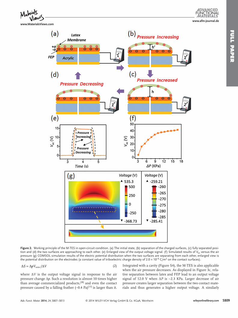
The operating principle of an M-TES is schematically illus-trated in Figure 2 . All of the schematics in this fi gure are plotted in two-dimensional cross-sectional view without showing the NRs. At the initial state, the latex membrane is in contact with the FEP fi lm. Due to the different triboelectric polari-ties between these two materials, [ 23 ] negative charges will be injected from the latex membrane to the FEP fi lm (Figure 2 a). Because of the law of charge conservation, the density of posi-tive charges (σ) on the latex is the same as that of negative ones on the FEP. In open-circuit condition, electrons cannot transfer between electrodes; and the triboelectric charges are uniformly distributed on the surfaces at macro scale with neg-ligible decay. [ 24,25 ] Once a pressure change occurs from the air-conducting channel, the latex membrane will begin to swell and separate from the FEP due to deformation, forming an arc-shaped air cavity in between. The maximum distance between the membrane and the FEP surface occurs at the center of the
device (Figure 2 b). Such a separation results in a potential difference established between the two electrodes (Figure 2 e), which is caused by the electric fi eld leakage at the edges of the fi nite-sized electrodes. [ 26,27 ] The potential difference will reach its maximum value when the pressure of the air cavity and the ambient pressure reach an equilib-rium (Figure 2 c and 2 e). If the air pressure drops, the membrane starts to approach the FEP fi lm due to its elasticity. Then, the elec-tric potential difference will decrease from the maximum value back to zero until a fully contact is achieved again (Figure 2 d and 2 e). Therefore, the M-TES is capable of dynamic air pressure change sensing. If we assume that the air is an ideal gas and the change of air pressure is isothermal, the air pressure change (Δ P ) can be calculated as below:
P P P P W W W( )/0 0 0Δ = − = − (1)
where P is the air pressure after changing, P 0 is the original air pressure that is approxi-mated by the standard atmospheric pressure
(101.3 KPa), W and W 0 are the total volume after and before the change, respectively (Supporting Information). As shown in Figure 2 f and 2 g, a simulation plot via COMSOL presents an electric potential difference between two electrodes in open-cir-cuit condition (a constant value of triboelectric charge density of 2.0 × 10 −6 C/m 2 on the FEP surface). Figure 2 f illustrates the simulated maximum value of the electric potential difference ( V oc ) versus Δ P , indicating a linear relationship in the range from 3.1 KPa to 12.2 KPa. Then, the V oc reaches saturation when the pressure exceeds the linear range.
To quantify the performance of an M-TES, a motor (LinMot, Inc.) that can provide linear reciprocating motion was used to drive a syringe in connection to the air-conducting channel of the device. As revealed in Figure 3 a, a periodic change of air pressure (Δ P = 7.1 KPa) at a frequency of 0.3 Hz generates an oscillating voltage signal around 14.5 V at the same frequency. Different ranges of Δ P result in diverse voltage signals. As illus-trated in Figure 3 b, a minor V oc of 0.2 V is obtained when Δ P is 3.1 KPa. If the air pressure changes in a wider range (Δ P = 9.4 KPa), the V oc shoots to 20.4 V, which is because larger Δ P expands the deformation of the membrane, thus an enhanced output voltage signal can be expected. Consistent with the sim-ulated results, saturation occurs when Δ P is beyond 9.9 KPa, which indicates that the device reaches its detection limit. Such a saturation is caused by the reason that the deformation of the membrane has reached its elastic limit, which makes triboelec-tric charges on the membrane have little infl uence on the elec-tric fi eld distribution around electrodes. [ 26 ] An approximately linear relationship ( R 2 = 0.98) between V oc and Δ P can be real-ized by the M-TES when Δ P ranges from 3.1 KPa to 9.4 KPa, corresponding to an average sensitivity of 3.2 V/KPa. Since the Root Mean Square (RMS) of the noise ( V noise ) at 1 Hz is 1.1 mV (Figure S3), the air pressure resolution at bandwidth of 1 Hz (Δ S ) can be calculated to be 0.34 Pa by the following equation:
Adv. Funct. Mater. 2014, 24, 5807–5813
www.afm-journal.dewww.MaterialsViews.com
Figure 1. (a) Schematic of the M-TES. (b) SEM image of FEP nanorod arrays. (c) Photograph of an M-TES and (d) an M-TES with the latex membrane swelling.
FULL P
APER
5809wileyonlinelibrary.com© 2014 WILEY-VCH Verlag GmbH & Co. KGaA, Weinheim
S pV V/noiseΔ = Δ Δ (2)
where Δ V is the output voltage signal in response to the air pressure change Δ p . Such a resolution is almost 10 times higher than average commercialized products, [ 28 ] and even the contact pressure caused by a falling feather (∼0.4 Pa) [ 13 ] is larger than it.
Integrated with a cavity (Figure S4), the M-TES is also applicable when the air pressure decreases. As displayed in Figure 3 c, rela-tive separation between latex and FEP lead to an output voltage signal of 12.0 V when Δ P is −2.3 KPa. Larger decrease of air pressure creates larger separation between the two contact mate-rials and thus generates a higher output voltage. A similarly
Adv. Funct. Mater. 2014, 24, 5807–5813
www.afm-journal.dewww.MaterialsViews.com
Figure 2. Working principle of the M-TES in open-circuit condition. (a) The initial state, (b) separation of the charged surfaces, (c) fully separated posi-tion and (d) the two surfaces are approaching to each other. (e) Enlarged view of the output voltage signal. (f) Simulated results of V oc versus the air pressure (g) COMSOL simulation results of the electric potential distribution when the two surfaces are separating from each other, enlarged view is the potential distribution on the electrodes (a constant value of triboelectric charge density of 2.0 × 10 −6 C/m 2 on the contact surfaces).

FULL
PAPER
5810 wileyonlinelibrary.com © 2014 WILEY-VCH Verlag GmbH & Co. KGaA, Weinheim
linear relationship between the V oc and Δ P can be achieved in Figure 3 d in which the V oc increases from 0.06 V to 15.8 V when Δ P decreases from −1.2 KPa to −3.5 KPa. Moreover, the output signal also reaches saturation around 16 V once Δ P is below −3.2 KPa. Therefore, the M-TES can be generally utilized when the pressure changes in other way with a sensitivity of 6.9 V/KPa, corresponding to a higher resolution of 0.16 Pa.
For structural optimization, the relationship between the sensitivity and the dimension of the M-TES is investigated. Output voltage signals from M-TESs with different circular apparent areas of 7.3 cm 2 , 3.2 cm 2 , and 0.8 cm 2 are measured when the air pressure changes in a small range (2.3 KPa < Δ P < 6 .2 KPa). As shown in Figure 4 a, the M-TES with an apparent areas of 7.3 cm 2 exhibits an excellent linear relationship
Adv. Funct. Mater. 2014, 24, 5807–5813
www.afm-journal.dewww.MaterialsViews.com
Figure 3. (a) V oc of the M-TES when air pressure increases. (b) Dependence of V oc on the increased air pressure. (c) V oc of the M-TES when air pressure decreases. (b) Dependence of V oc on the decreased air pressure.
Figure 4. (a) Sensitivity of an M-TES with an effective contact area of 7.3 cm 2 . (b) Sensitivity of an M-TES with an effective contact area of 3.2 cm 2 . (c) Sensitivity of an M-TES with an effective contact area of 0.8 cm 2 . (d) V oc of M-TES when air pressure periodically changed from 101.3 KPa to 108.4 KPa at different frequencies. (e) Stability of the M-TES after longtime operation.
FULL P
APER
5811wileyonlinelibrary.com© 2014 WILEY-VCH Verlag GmbH & Co. KGaA, Weinheim
( R 2 = 0.98) between its output voltage (Δ V ) and Δ P . The Δ V goes ups from 0.02 V to 0.15 V when Δ P increases from 3.0 KPa to 6.2 KPa, corresponding to a linear fi tting curve that can be expressed as
0.04 0.08V PΔ = Δ − (3)
Thus, the average sensitivity of the M-TES is 0.04 V/KPa. Likewise, good linear relationships between Δ V and Δ P can also be obtained in M-TESs with smaller apparent areas of 3.2 cm 2 ( R 2 = 0.95) and 0.8 cm 2 ( R 2 = 0.98). However, sensitivities of M-TESs vary with apparent areas. According to Figure 4 b and 4 c, a sensitivity of 0.33 V/KPa when Δ P changes from 2.9 KPa to 3.4 KPa can be achieved by an M-TES with an apparent area of 3.2 cm 2 , while a higher sensitivity of 0.44 V/KPa in the range from 2.3 KPa to 3.2 KPa can be achieved by an M-TES with a smaller apparent area of 0.8 cm 2 . Such an effect of the apparent area on
the sensitivity of an M-TES can be explained by the reason that larger deformation of the membrane occurs for the device with smaller circular apparent area within the same range of pres-sure change. As a result, a higher sensitivity can be expected if a smaller device is used. It is to be noted that the sensitivity of the M-TES for a small range of Δ P differs from that for a large range since the separation between the membrane and the FEP is not linearly dependent on the pressure change. In addition, smaller apparent area reduces the elastic limit of the mem-brane, resulting in a decreased detection limit of an M-TES. Furthermore, to investigate possible impacts on the electric output signal of an M-TES from the frequency of the air pres-sure change, the V oc of an M-TES with an apparent area of 3.2 cm 2 is measured when air pressure periodically changes (Δ P = 7.1 KPa) at different frequencies. It can be concluded from Figure 4 d that the frequency has little impact on output signals of M-TES when the frequency reduces from 1.0 Hz to 0.2 Hz.
Adv. Funct. Mater. 2014, 24, 5807–5813
www.afm-journal.dewww.MaterialsViews.com
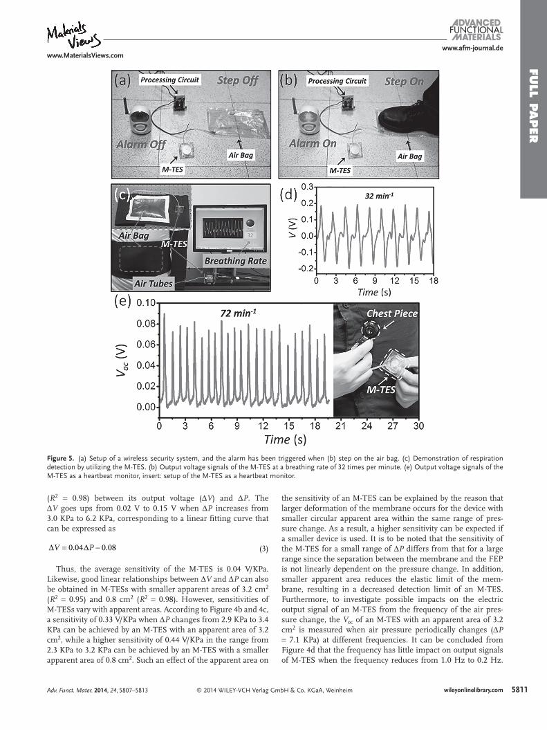
Figure 5. (a) Setup of a wireless security system, and the alarm has been triggered when (b) step on the air bag. (c) Demonstration of respiration detection by utilizing the M-TES. (b) Output voltage signals of the M-TES at a breathing rate of 32 times per minute. (e) Output voltage signals of the M-TES as a heartbeat monitor, insert: setup of the M-TES as a heartbeat monitor.
FULL
PAPER
5812 wileyonlinelibrary.com © 2014 WILEY-VCH Verlag GmbH & Co. KGaA, Weinheim Adv. Funct. Mater. 2014, 24, 5807–5813
www.afm-journal.dewww.MaterialsViews.com
This is due to the fact that the V oc depends on the static posi-tion of the membrane, which is independent of the dynamic frequency. Moreover, the stability of the M-TES was investigated by long-time operation under the circumstance where air pres-sure periodically changed (Δ P = 7.1 KPa) at a frequency of 0.3 Hz. After 10,000 cycles (Figure S5), the output voltage signal still keeps constant around 14.5 V (Figure 4 e), which indicates a strong stability of the M-TES.
To demonstrate the ability of M-TESs as active air pressure sensors, three sets of practical applications were demonstrated. As demonstrated in Figure 5 a, a wireless security system is built by integrating an M-TES, an air bag (12 × 18 × 1 cm), a processing circuit (Figure S6), and a safety alarm (Home Safe, Inc.). The M-TES was able to generator a voltage signal due to a pressure change when the air bag is pressed; and such a voltage signal could trigger the security alarm though the pro-cessing circuit (Figure 5 b, Video S1 in Supporting Informa-tion). Compared to traditional technologies, the M-TES can pro-vide a simple and reliable way to achieve a security monitoring system or a motion detection technology. Air pressure sensors can be utilized for respiration detection in various fi elds such as medicine and nursing. [ 28 ] Here in this work, we demon-strate a simple and low-cost system for respiration detection by using M-TESs. As sketched inserted in Figure 5 c, an air bag (18 × 22 × 1 cm) with air tubes was connected with an M-TES. An adjustable back brace is used to attach the air bag to the abdomen of a subject. The abdominal expansion and contrac-tion of respiratory activity will result in a periodical air pres-sure change in the air bag which can be detected by the M-TES. Once the respiratory movement occurs, output voltage signals generated by the M-TES will be collected by a program devel-oped by LabView; and the average breathing rate in real time displays on the monitor (Figure 5 c). Electric signals indicate a breathing rate of 32 times per minute when the subject carries on a normal breathing rate (Figure 5 d). Inspirations caused by pulmonary expansion are shown as maxima peaks, while expi-rations caused by pulmonary contraction are shown as minima ones (see Video S2 in Supporting Information). Heartbeat monitors has been largely used by performers of various types of physical exercise and medical purposes. Due to the high res-olution, we successfully demonstrate a heartbeat monitor based on the M-TES. Air pressure change in a chest piece is caused by the heartbeat transmit via air-fi lled hollow tubes to the M-TES (inserted in Figure 5 e). Such a periodical air pressure change will result in output voltage signals for the M-TES. In such a case, each heartbeat can be recorded by a pulse signal. The output voltage signals around 0.06 V in Figure 5 e shows that the test subject has a stable heartbeat rate of 72 times per minute which is consistent with the counting result. Therefore, in our proposed method, the obtained breathing and heart-beat rate can be successfully obtained by output voltage sig-nals, which can be applied for easy handling detection systems required for daily home use.
3. Conclusion
In summary, we demonstrate membrane-based triboelectric sensors as self-powered air pressure sensors with extremely
high resolutions for surveillance and health Monitoring. The small-sized and light-weighted M-TES provides an effective way to detect the air pressure change for circumstances when air pressure increases or decreases. The device shows strong sta-bility after longtime operation, and higher sensitivity can be expected when the device is further miniaturized. Furthermore, output voltage signals can be directly utilized for air pressure sensing, frequency monitoring, and other practical applica-tions. Given its good linearity, easy fabrication process and low cost, the M-TES presented in this work can be further applied for water depth sensing, health monitoring as well as for other self-powered monitoring systems.
Supporting Information Supporting Information is available from the Wiley Online Library or from the author.
Acknowledgements P. Bai and G. Zhu contributed equally to this work. This research was supported by the “thousands talents” program for pioneer researcher and his innovation team, China. P. Bai thanks the support from the Chinese Scholars Council. Patents have been fi led based on the research results presented in this manuscript.
Received: April 19, 2014 Revised: May 13, 2014
Published online: July 16, 2014
[1] S. J. Pearton , B. S. Kang , S. Kim , F. Ren , B. P. Gila , C. R. Abernathy , J. Lin , S. N. G. Chu , J. Phy.: Condens. Matter. 2004 , 16 , R961 .
[2] A. Lloyd Spetz , A. Baranzahi , P. Tobias , I. Lundström , Phys. Status Solidi A 1997 , 162 , 493 .
[3] J. Kim , F. Ren , B. P. Gila , C. R. Abernathy , S. J. Pearton , Appl. Phys. Lett. 2003 , 82 , 739 .
[4] S. Roy , S. Basu , B. Mater. Sci. 2002 , 25 , 513 . [5] A. Kooser , R. L. Gunter , W. D. Delinger , T. L. Porter , M. P. Eastman ,
Sensor. Actuat. B-Chem. 2004 , 99 , 474 . [6] C. S. Sander , J. W. Knutti , J. D. Meindl , IEEE T. Electron. Dev. 1980 ,
27 , 927 . [7] P. A. Snow , E. K. Squire , P. S. J. Russell , L. T. Canham , J. Appl. Phys.
1999 , 86 , 1781 . [8] Z. L. Wang , W. Wu , Angew. Chem., Int. Ed. 2012 , 51 , 11700 . [9] Z. L. Wang , J. Song , Science 2006 , 312 , 242 .
[10] Z. L. Wang , Sci. Am. 2008 , 298 , 82 . [11] I. F. Akyildiz , J. M. Jornet , Nano Commun. Networks 2010 , 1 , 3 . [12] F.-R. Fan , L. Lin , G. Zhu , W. Wu , R. Zhang , Z. L. Wang , Nano Lett.
2012 , 12 , 3109 . [13] J. Chen , G. Zhu , W. Yang , Q. Jing , P. Bai , Y. Yang , T. C. Hou ,
Z. L. Wang , Adv. Mater. 2013 , 25 , 6094 . [14] Z.-H. Lin , G. Zhu , Y. Zhou , Y. Yang , P. Bai , J. Chen , Z. L. Wang ,
Angew. Chem. 2013 , 19 , 5065 . [15] F.-R. Fan , Z.-Q. Tian , Z. L. Wang , Nano Energy 2012 , 1 , 328 . [16] B. Meng , W. Tang , X. S. Zhang , M. D. Han , W. Liu , H. X. Zhang ,
Nano Energy 2013 , 6 , 1101 . [17] S. Wang , L. Lin , Z. L. Wang , Nano Lett. 2012 , 12 , 6339 . [18] P. Bai , G. Zhu , Y. Liu , J. Chen , Q. Jing , W. Yang , J. Ma , G. Zhang ,
Z. L. Wang , ACS Nano 2013 , 7 , 6361 .

FULL P
APER
5813wileyonlinelibrary.com© 2014 WILEY-VCH Verlag GmbH & Co. KGaA, WeinheimAdv. Funct. Mater. 2014, 24, 5807–5813
www.afm-journal.dewww.MaterialsViews.com
[19] G. Zhu , J. Chen , T. Zhang , Q. Jing , Z. L. Wang , Nat. Commun. 2014 , 5 , 3426 .
[20] G. Zhu , Z.-H. Lin , Q. Jing , P. Bai , C. Pan , Y. Yang , Y. Zhou , Z. L. Wang , Nano Lett. 2013 , 13 , 847 .
[21] P. Bai , G. Zhu , Z.-H. Lin , Q. Jing , J. Chen , G. Zhang , J. Ma , Z. L. Wang , ACS Nano 2013 , 7 , 3713 .
[22] H. Fang , W. Wu , J. Song , Z. L. Wang , J. Phys. Chem. C 2009 , 113 , 16571 .
[23] A. F. Diaz , R. M. Felix-Navarro , J. Electrostat. 2004 , 62 , 277 .
[24] F. Saurenbach , D. Wollmann , B. D. Terris , A. F. Diaz , Langmuir 1992 , 8 , 1199 .
[25] L. H. Lee , J. Electrostat. 1994 , 32 , 1 . [26] S. Niu , Y. Liu , S. Wang , L , Lin , Y. Zhou , Y. Hu , Z. L. Wang , Adv.
Funct. Mater. 2014 , 24 , 3332 . [27] Y. Yang , Y. S. Zhou , H. Zhang , Y. Liu , S. Lee , Z. L. Wang , Adv. Mater.
2013 , 25 , 6594 . [28] K. Ho , N. Tsuchiya , H. Nakajima , K. Kuramoto , S. Kobashi , Y. Hata ,
Proc. 2009 IEEE Int. Conf. Fuzzy Systems 2009 , 911 .