
MEMBER TABLES F17...SEASONED HARDWOOD — F17 Bearer Span Floor Load Width (FLW) mm 1200 1800 2400...
36
● SIZING TOLERANCES Not less than nominated size F17 SEASONED MEMBER TABLES FOR SEASONED TIMBER STRESS GRADE F17 SEASONED HARDWOOD — F17 129
Transcript of MEMBER TABLES F17...SEASONED HARDWOOD — F17 Bearer Span Floor Load Width (FLW) mm 1200 1800 2400...

● SIZING TOLERANCES
Not less than nominated size
F17SEASONED
MEMBER TABLESFORSEASONEDTIMBER
STRESS GRADE F17
SEASONED HARDWOOD — F17 129

SEASONED HARDWOOD — F17
TABLE 1A — BEARERS SUPPORTING SINGLE STOREY LOADBEARING WALLSMaximum Floor Load Width – 1800mm
132
Sheet Roofing Tiled Roofing
Roof Load Width (RLW) mm1500 2100 4500 7500 1500 2100 4500 7500
MAXIMUM SPAN OF BEARER (mm)Single Span
2 / 85 x 30 1200 1200 1100 1000 1100 1100 NS NS2 / 85 x 40 1400 1300 1200 1100 1200 1200 1000 NS2 / 90 x 35 1400 1300 1200 1100 1300 1200 1000 NS2 / 90 x 45 1500 1500 1300 1200 1400 1300 1100 1000
2 / 120 x 35 1800 1800 1600 1500 1700 1600 1400 12002 / 120 x 45 2000 2000 1800 1600 1900 1800 1500 1300
Continuous Spans2 / 85 x 30 1700 1600 1500 1400 1600 1500 1300 11002 / 85 x 40 1900 1800 1600 1500 1700 1600 1400 13002 / 90 x 35 1900 1800 1700 1500 1700 1700 1400 13002 / 90 x 45 2000 2000 1800 1700 1900 1800 1600 1400
2 / 120 x 35 2500 2500 2200 2000 2300 2200 1900 17002 / 120 x 45 2700 2700 2400 2200 2500 2400 2100 1800
Bearer Size
Depth x Breadth(mm)
NS = Not suitable.Note: 1. Table assumes a maximum flooring mass of 40kg/m2.
2. Footing and stump details shall be determined in conjunction with the selection of bearers, refer AS1684.3. Double members shall be vertically nail laminated in accordance with Figure 1.9.

SEASONED HARDWOOD — F17
Bearer
Span
Floor Load Width (FLW) mm
1200 1800 2400 3000 3600
MAXIMUM SPAN OF BEARER (mm)Single Span
2 / 85 x 30 1600 1400 1300 1200 1100
2 / 85 x 40 1800 1600 1400 1300 1200
2 / 90 x 35 1800 1600 1400 1300 1200
2 / 90 x 45 2000 1700 1600 1400 1300
2 / 120 x 35 2500 2100 1900 1800 1700
2 / 120 x 45 2700 2300 2100 1900 1800
Continuous Spans2 / 85 x 30 2100 1800 1600 1500 1400
2 / 85 x 40 2300 2000 1800 1700 1600
2 / 90 x 35 2300 2000 1800 1700 1600
2 / 90 x 45 2500 2200 2000 1800 1800
TABLE 5 — BEARERS SUPPORTING FLOOR LOAD ONLY
Bearer Size
Depth x Breadth(mm)
Refer to Fig. 1.13.2 for detailed diagram
136

137
Floor Load Width (FLW) mm
1200 1800 2400 3000 3600
MAXIMUM SPAN OF BEARER (mm)Continuous Spans (continued)
2 / 120 x 35 3100 2700 2500 2300 2200
2 / 120 x 45 3400 3000 2700 2500 2400
TABLE 5 — BEARERS SUPPORTING FLOOR LOAD ONLY (continued)
Bearer Size
Depth x Breadth(mm)
Note: 1. Table assumes a maximum flooring mass of 40kg/m2.2. Footing and stump details shall be determined in conjunction with the selection of bearers, refer AS1684.3. Double members shall be vertically nail laminated in accordance with Figure 1.9.
SEASONED HARDWOOD — F17
SEASONED HARDWOOD — F17
Joist
Spacing
JoistSpan
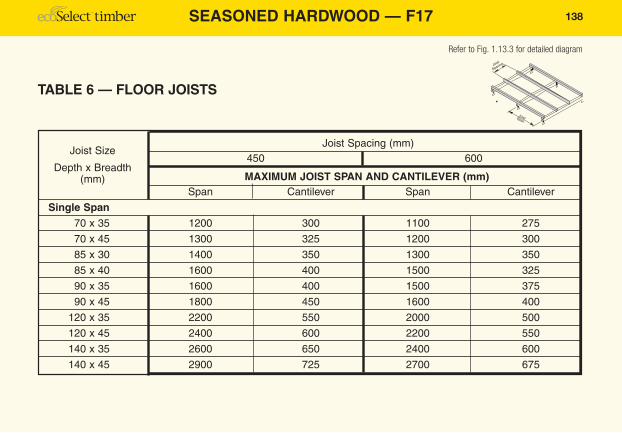
Joist Spacing (mm)450 600
MAXIMUM JOIST SPAN AND CANTILEVER (mm)Span Cantilever Span Cantilever
Single Span70 x 35 1200 300 1100 275
70 x 45 1300 325 1200 300
85 x 30 1400 350 1300 350
85 x 40 1600 400 1500 325
90 x 35 1600 400 1500 375
90 x 45 1800 450 1600 400
120 x 35 2200 550 2000 500
120 x 45 2400 600 2200 550
140 x 35 2600 650 2400 600
140 x 45 2900 725 2700 675
TABLE 6 — FLOOR JOISTS
Joist Size
Depth x Breadth(mm)
Refer to Fig. 1.13.3 for detailed diagram
138
139
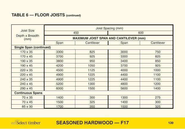
Joist Spacing (mm)450 600
MAXIMUM JOIST SPAN AND CANTILEVER (mm)Span Cantilever Span Cantilever
Single Span (continued)170 x 35 3300 825 3000 750170 x 45 3700 925 3300 825190 x 35 3800 950 3400 850190 x 45 4200 1050 3700 925220 x 35 4500 1125 4000 1000220 x 45 4900 1225 4400 1100240 x 35 4900 1225 4400 1100240 x 45 5200 1300 4800 1200290 x 45 6000 1500 5600 1400
Continuous Spans70 x 35 1400 300 1300 27570 x 45 1500 325 1400 30085 x 30 1700 350 1500 325
TABLE 6 — FLOOR JOISTS (continued)
Joist Size
Depth x Breadth(mm)
SEASONED HARDWOOD — F17

SEASONED HARDWOOD — F17
TABLE 6 — FLOOR JOISTS (continued)
140
Joist Spacing (mm)450 600
MAXIMUM JOIST SPAN AND CANTILEVER (mm)Span Cantilever Span Cantilever
Continuous Spans (continued)85 x 40 1900 400 1700 37590 x 35 1900 400 1700 37590 x 45 2100 450 1900 400
120 x 35 2600 550 2400 500120 x 45 2900 600 2600 550
Joist Size
Depth x Breadth(mm)
Note: 1. Cantilevers shall not exceed 50% of the actual backspan.2. The allowable cantilevers are only applicable to floor loads.3. Joists crippled over supports shall be considered as single span joists.4. Table assumes a maximum flooring mass of 40kg/m2.

Rafter or Truss Spacing
RLW
Lintel
Span
Sheet Roofing Tiled Roofing
Roof Load Width (RLW) mm
1500 2100 4500 7500 1500 2100 4500 7500
MAXIMUM SPAN OF LINTEL (mm)90 x 35 600 2000 1800 1400 1200 1600 1400 1100 900
1200 2000 1800 1200 1000 1400 1200 800 600
90 x 45 600 2200 1900 1500 1300 1600 1400 1100 10001200 2200 1900 1400 1100 1600 1300 900 700
120 x 35 600 2600 2300 1800 1500 2000 1700 1400 11001200 2600 2300 1700 1400 2000 1700 1200 900
120 x 45 600 2800 2400 1900 1600 2100 1800 1500 12001200 2800 2500 1900 1500 2100 1900 1300 1000
140 x 35 600 2900 2600 2100 1700 2200 2000 1600 13001200 2900 2700 2000 1700 2300 2000 1400 1100
140 x 45 600 3100 2800 2200 1900 2400 2100 1700 14001200 3100 2800 2200 1900 2500 2100 1600 1300
TABLE 17/18 — LINTELS Supporting Single orUpper Storey Loadbearing Walls
Lintel Size
Depth xBreadth
(mm)
Rafteror
TrussSpacing
(mm)
Refer to Fig. 1.13.10 for detailed diagram
141SEASONED HARDWOOD — F17

SEASONED HARDWOOD — F17
TABLE 17/18 — LINTELS Supporting Single orUpper Storey Loadbearing Walls (continued)
142
Sheet Roofing Tiled Roofing
Roof Load Width (RLW) mm
1500 2100 4500 7500 1500 2100 4500 7500
MAXIMUM SPAN OF LINTEL (mm)170 x 35 600 3400 3100 2500 2100 2700 2400 1900 1600
1200 3400 3100 2500 2000 2700 2400 1900 1500170 x 45 600 3600 3300 2700 2200 2900 2600 2000 1700
1200 3500 3200 2700 2200 2900 2600 2000 1600190 x 35 600 3600 3300 2700 2300 3000 2700 2100 1700
1200 3600 3300 2800 2300 3000 2700 2100 1700190 x 45 600 3900 3500 3000 2500 3200 2900 2300 1900
1200 3800 3500 3000 2500 3200 2900 2200 19002 / 190 x 35 600 4300 3900 3300 2900 3500 3200 2600 2200
1200 4300 3900 3300 2900 3500 3200 2700 2200220 x 35 600 4000 3700 3100 2600 3300 3000 2400 2000
1200 4000 3700 3100 2700 3300 3000 2400 2000220 x 45 600 4300 3900 3300 2900 3500 3200 2600 2200
1200 4200 3900 3200 2900 3500 3200 2600 2100
Lintel Size
Depth xBreadth
(mm)
Rafteror
TrussSpacing
(mm)

143
Sheet Roofing Tiled Roofing
Roof Load Width (RLW) mm
1500 2100 4500 7500 1500 2100 4500 7500
MAXIMUM SPAN OF LINTEL (mm)2 / 220 x 35 600 4700 4300 3600 3200 3900 3600 3000 2500
1200 4700 4300 3600 3200 3900 3600 3000 2600
240 x 35 600 4300 4000 3300 2900 3600 3300 2600 22001200 4300 3900 3300 2900 3500 3200 2700 2200
240 x 45 600 4600 4200 3500 3100 3800 3500 2800 2400
1200 4600 4200 3500 3100 3800 3400 2900 2400
2 / 240 x 35 600 5100 4600 3900 3500 4200 3800 3200 28001200 5100 4600 3900 3400 4200 3800 3200 2800
2 / 240 x 45 600 5300 4900 4200 3700 4400 4100 3400 30001200 5300 4900 4200 3600 4400 4100 3400 3000
290 x 45 600 5300 4800 4100 3600 4300 4000 3300 29001200 5300 4800 4000 3500 4300 4000 3300 2900
2 / 290 x 45 600 6100 5600 4800 4200 5100 4700 3900 35001200 6100 5600 4800 4200 5100 4700 3900 3400
TABLE 17/18 — LINTELS Supporting Single orUpper Storey Loadbearing Walls (continued)
SEASONED HARDWOOD — F17
Note: 1. Double members shall be vertically nail laminated in accordance with Figure 1.9.2. Lintels to internal wall openings supporting ceiling joists only may be sized as hanging beams.
Lintel Size
Depth xBreadth
(mm)
Rafteror
TrussSpacing
(mm)

SEASONED HARDWOOD — F17
Roof Load Width (mm)
1500 2100 4500 75005 10 20 5 10 20 5 10 20 5 10 20
MAXIMUM SPAN OF LINTEL (mm)
Sheet Roof90 x 35 1100 800 600 1100 800 600 1000 800 600 900 700 60090 x 45 1200 900 700 1200 900 600 1100 900 600 1000 800 600
120 x 35 1600 1200 900 1500 1200 800 1300 1100 800 1200 1000 800120 x 45 1700 1300 1000 1700 1300 900 1500 1200 900 1300 1100 900140 x 35 1900 1400 1100 1800 1400 1000 1600 1300 1000 1400 1200 1000140 x 45 2100 1600 1200 2000 1600 1200 1700 1500 1100 1600 1300 1100170 x 35 2400 1900 1400 2300 1800 1400 2000 1700 1300 1800 1500 1300170 x 45 2600 2100 1600 2500 2000 1500 2200 1900 1500 1900 1700 1400190 x 35 2700 2200 1600 2600 2100 1600 2200 1900 1500 2000 1800 1500190 x 45 3000 2400 1800 2900 2400 1800 2500 2100 1700 2200 1900 1600
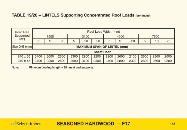
TABLE 19/20 – LINTELS Supporting Concentrated Roof Loads
Roof AreaSupported
(m2)
Size DxB (mm)
Refer to Fig. 1.13.11 for detailed diagram
144
145
TABLE 19/20 – LINTELS Supporting Concentrated Roof Loads (continued)
SEASONED HARDWOOD — F17
Roof Load Width (mm)
1500 2100 4500 75005 10 20 5 10 20 5 10 20 5 10 20
MAXIMUM SPAN OF LINTEL (mm)
Sheet Roof240 x 35 3400 3000 2300 3300 2900 2200 2900 2600 2100 2600 2300 2000240 x 45 3700 3200 2600 3500 3100 2500 3100 2800 2300 2800 2600 2200
Roof AreaSupported
(m2)
Size DxB (mm)
Note: 1. Minimum bearing length = 35mm at end supports.

SEASONED HARDWOOD — F17
TABLE 19/20 – LINTELS Supporting Concentrated Roof Loads (continued)
146
Roof Load Width (mm)
1500 2100 4500 75005 10 20 5 10 20 5 10 20 5 10 20
MAXIMUM SPAN OF LINTEL (mm)
Tile Roof90 x 35 800 NS NS 700 NS NS 700 NS NS 600 NS NS90 x 45 800 600 NS 800 600 NS 700 600 NS 700 NS NS
120 x 35 1100 800 NS 1000 800 NS 900 700 NS 900 700 NS120 x 45 1200 900 NS 1100 900 NS 1000 800 NS 900 800 NS140 x 35 1300 1000 NS 1300 1000 NS 1100 900 NS 1000 800 NS140 x 45 1400 1100 NS 1400 1100 NS 1200 1000 NS 1100 900 NS170 x 35 1700 1300 NS 1600 1200 NS 1400 1200 NS 1300 1100• NS170 x 45 1900 1400 700 1800 1400 700 1600 1300 600 1400 1200 600190 x 35 1900 1500 600• 1800 1500 600• 1600 1300 600• 1400 1200• 600➤
190 x 45 2200 1700 900 2100 1600 900 1800 1500 800• 1600 1400 800•
Roof AreaSupported
(m2)
Size DxB (mm)

147
TABLE 19/20 – LINTELS Supporting Concentrated Roof Loads (continued)
SEASONED HARDWOOD — F17
Roof Load Width (mm)
1500 2100 4500 75005 10 20 5 10 20 5 10 20 5 10 20
MAXIMUM SPAN OF LINTEL (mm)
Tile Roof240 X 35 2600 2100 1000➤ 2500 2000 1000➤ 2100 1800• 1000■ 1900 1700➤ 900■
240 X 45 2900 2300 1700➤ 2700 2200 1700➤ 2400 2000 1400➤ 2100 1900• 1300■
Roof AreaSupporting
(m2)
Size DxB (mm)
Note: 1. Minimum bearing length = 35 mm at end supports.• Additional 5 mm bearing length required.➤ Additional 10 mm bearing length required.■ Additional 15 mm bearing length required.

SEASONED HARDWOOD — F17
Hanging Beam
Span"W"
Ceiling Load Width (CLW) mm1800 2400 3000 3600 4200
MAXIMUM SPAN OF HANGING BEAM (mm)120 x 35 3100 2700 2500 2300 2200
140 x 35 3500 3200 2900 2700 2500
170 x 35 4300 3800 3500 3300 3100
190 x 35 4700 4300 3900 3600 3400
220 x 35 5500 5000 4600 4200 3900
220 x 45 5900 5400 4900 4600 4300
240 x 35 5900 5300 4900 4600 4300
240 x 45 6300 5700 5300 4900 4600
TABLE 23 — HANGING BEAMS
Beam Size
Depth x Breadth(mm)
Note: 1. Where the ceiling joist spans are not the same each side of the hanging beam, the average of the spans maybe used.
2. Roof loads must not be strutted onto hanging beam.3. Maximum ceiling mass of 12kg/m2 assumed.
Refer to Fig. 1.13.13 for detailed diagram
148

Counter BeamSpan
"L"
Ceiling Load Width (mm)1800 2400 3000 3600 4200 4800
MAXIMUM SPAN OF COUNTER BEAM (mm)120 x 35 3100 2800 2600 2500 2400 2300
120 x 45 3300 3100 2900 2700 2600 2500
140 x 35 3600 3300 3100 2900 2800 2600
140 x 45 3800 3600 3300 3100 3000 2900
170 x 35 4200 3900 3700 3500 3300 3200
170 x 45 4400 4100 3900 3800 3600 3500
190 x 35 4500 4200 4000 3900 3700 3600
190 x 45 4800 4500 4300 4100 4000 3800
220 x 35 5100 4800 4600 4400 4200 4100
220 x 45 5400 5100 4800 4600 4500 4300
240 x 35 5400 5000 4800 4600 4400 4300
240 x 45 5700 5300 5100 4900 4700 4600
TABLE 24 — COUNTER BEAMS
Beam Size
Depth x Breadth(mm)
Refer to Fig. 1.13.14 for detailed diagram
149SEASONED HARDWOOD — F17
SEASONED HARDWOOD — F17
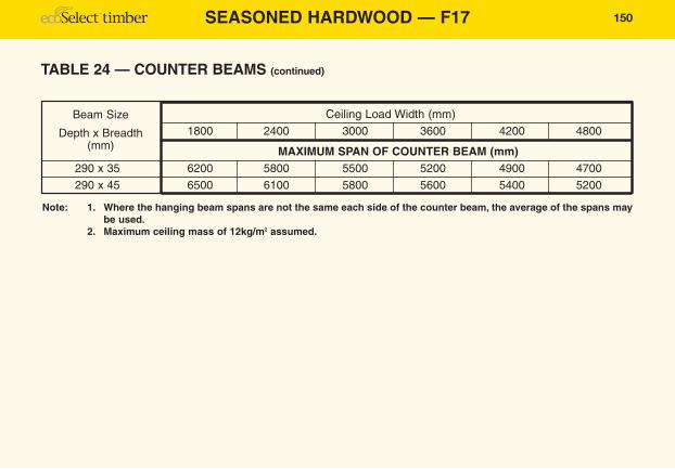
TABLE 24 — COUNTER BEAMS (continued)
150
Ceiling Load Width (mm)1800 2400 3000 3600 4200 4800
MAXIMUM SPAN OF COUNTER BEAM (mm)290 x 35 6200 5800 5500 5200 4900 4700
290 x 45 6500 6100 5800 5600 5400 5200
Beam Size
Depth x Breadth(mm)
Note: 1. Where the hanging beam spans are not the same each side of the counter beam, the average of the spans maybe used.
2. Maximum ceiling mass of 12kg/m2 assumed.

Combined Hanging/Struttin
g Beam
Span
"A"
"W"
"B"
Ceiling Load Width (mm)
1800 3600
Roof Area Supported (m2)
2 4 6 8 10 2 4 6 8 10
MAXIMUM SPAN OF BEAM (mm)Sheet Roofing
2 / 120 x 35 3000 2600 2200 2000 1800 2500 2200 2000 1900 1700
2 / 120 x 45 3300 2800 2500 2200 2100 2700 2500 2200 2100 1900
2 / 140 x 35 3600 3100 2700 2500 2300 3000 2700 2500 2300 2100
2 / 140 x 45 3800 3400 3000 2800 2500 3200 3000 2700 2500 2400
2 / 170 x 35 4200 3800 3500 3200 3000 3600 3400 3100 2900 2700
2 / 170 x 45 4400 4100 3800 3500 3300 3900 3600 3400 3200 3000
2 / 190 x 35 4500 4200 3900 3700 3400 4000 3700 3600 3300 3200
2 / 190 x 45 4800 4400 4200 3900 3700 4200 4000 3800 3700 3500
2 / 220 x 35 5200 4800 4500 4200 4000 4500 4200 4000 3900 3700
TABLE 25 — COMBINED STRUTTING/HANGING BEAMS
BeamSize(mm)
Refer to Fig. 1.13.15 for detailed diagram
151SEASONED HARDWOOD — F17

SEASONED HARDWOOD — F17
TABLE 25 — COMBINED STRUTTING/HANGING BEAMS (continued)
152
Ceiling Load Width (mm)
1800 3600
Roof Area Supported (m2)
2 4 6 8 10 2 4 6 8 10
MAXIMUM SPAN OF BEAM (mm)Sheet Roofing (continued)
2 / 220 x 45 5500 5100 4800 4500 4300 4700 4500 4300 4100 4000
2 / 240 x 35 5400 5000 4800 4500 4300 4700 4500 4300 4200 4000
2 / 240 x 45 5700 5300 5000 4800 4600 5000 4800 4600 4400 4300
2 / 290 x 35 6200 5800 5500 5300 5100 5500 5200 5000 4900 4700
2 / 290 x 45 6500 6200 5900 5600 5400 5800 5500 5300 5200 5000
Tiled Roofing
2 / 120 x 35 2400 1900 1600 1400 1200 2200 1800 1500 1300 1200
2 / 120 x 45 2700 2100 1800 1600 1400 2400 2000 1700 1500 1400
2 / 140 x 35 3000 2300 2000 1700 1600 2600 2200 1900 1700 1500
2 / 140 x 45 3300 2600 2200 2000 1800 2900 2400 2100 1900 1700
2 / 170 x 35 3700 3000 2600 2300 2100 3300 2800 2500 2200 2000
BeamSize(mm)
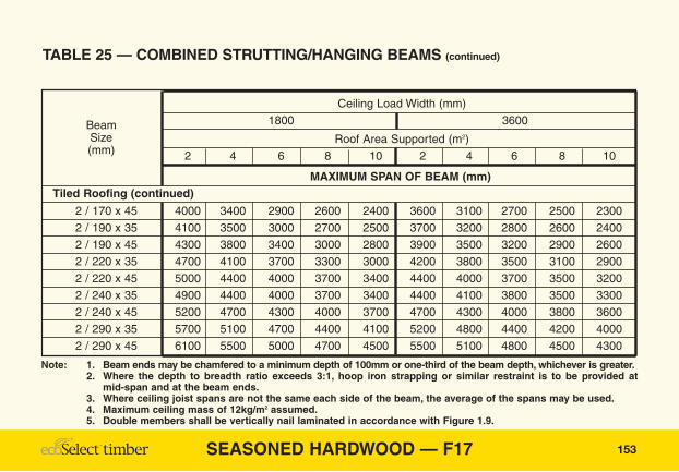
153
Ceiling Load Width (mm)
1800 3600
Roof Area Supported (m2)
2 4 6 8 10 2 4 6 8 10
MAXIMUM SPAN OF BEAM (mm)Tiled Roofing (continued)
2 / 170 x 45 4000 3400 2900 2600 2400 3600 3100 2700 2500 2300
2 / 190 x 35 4100 3500 3000 2700 2500 3700 3200 2800 2600 2400
2 / 190 x 45 4300 3800 3400 3000 2800 3900 3500 3200 2900 2600
2 / 220 x 35 4700 4100 3700 3300 3000 4200 3800 3500 3100 2900
2 / 220 x 45 5000 4400 4000 3700 3400 4400 4000 3700 3500 3200
2 / 240 x 35 4900 4400 4000 3700 3400 4400 4100 3800 3500 3300
2 / 240 x 45 5200 4700 4300 4000 3700 4700 4300 4000 3800 3600
2 / 290 x 35 5700 5100 4700 4400 4100 5200 4800 4400 4200 4000
2 / 290 x 45 6100 5500 5000 4700 4500 5500 5100 4800 4500 4300
TABLE 25 — COMBINED STRUTTING/HANGING BEAMS (continued)
BeamSize(mm)
Note: 1. Beam ends may be chamfered to a minimum depth of 100mm or one-third of the beam depth, whichever is greater.2. Where the depth to breadth ratio exceeds 3:1, hoop iron strapping or similar restraint is to be provided at
mid-span and at the beam ends.3. Where ceiling joist spans are not the same each side of the beam, the average of the spans may be used.4. Maximum ceiling mass of 12kg/m2 assumed.5. Double members shall be vertically nail laminated in accordance with Figure 1.9.
SEASONED HARDWOOD — F17

SEASONED HARDWOOD — F17
"A"
"B"
Combined Strutting/
Counter Beam Span
"L"
Ceiling Load Width (mm)
1800 3600
Roof Area Supported (m2)
2 4 6 8 10 2 4 6 8 10
MAXIMUM SPAN OF BEAM (mm)Sheet Roofing
2 / 120 x 35 3100 2600 2300 2000 1900 2800 2400 2200 2000 1800
2 / 120 x 45 3400 2900 2500 2300 2100 3000 2700 2400 2200 2000
2 / 140 x 35 3700 3200 2800 2500 2300 3300 2900 2600 2400 2200
2 / 140 x 45 3900 3500 3100 2800 2600 3600 3200 2900 2700 2500
2 / 170 x 35 4300 3900 3600 3300 3000 3900 3600 3300 3100 2900
2 / 170 x 45 4500 4100 3800 3600 3300 4100 3900 3600 3400 3200
2 / 190 x 35 4600 4200 4000 3700 3500 4200 4000 3700 3500 3300
2 / 190 x 45 4900 4500 4200 4000 3800 4500 4200 4000 3800 3600
2 / 220 x 35 5200 4800 4500 4200 4000 4800 4500 4200 4000 3900
TABLE 26 — COMBINED STRUTTING/COUNTER BEAMS
BeamSize(mm)
Refer to Fig. 1.13.16 for detailed diagram
154
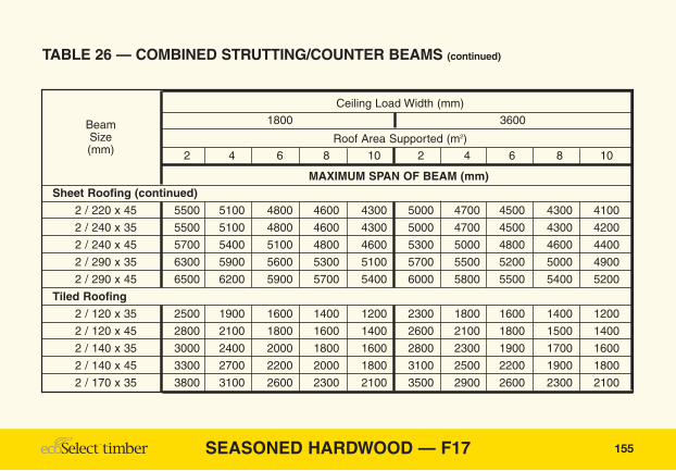
155SEASONED HARDWOOD — F17
Ceiling Load Width (mm)
1800 3600
Roof Area Supported (m2)
2 4 6 8 10 2 4 6 8 10
MAXIMUM SPAN OF BEAM (mm)Sheet Roofing (continued)
2 / 220 x 45 5500 5100 4800 4600 4300 5000 4700 4500 4300 4100
2 / 240 x 35 5500 5100 4800 4600 4300 5000 4700 4500 4300 4200
2 / 240 x 45 5700 5400 5100 4800 4600 5300 5000 4800 4600 4400
2 / 290 x 35 6300 5900 5600 5300 5100 5700 5500 5200 5000 4900
2 / 290 x 45 6500 6200 5900 5700 5400 6000 5800 5500 5400 5200
Tiled Roofing
2 / 120 x 35 2500 1900 1600 1400 1200 2300 1800 1600 1400 1200
2 / 120 x 45 2800 2100 1800 1600 1400 2600 2100 1800 1500 1400
2 / 140 x 35 3000 2400 2000 1800 1600 2800 2300 1900 1700 1600
2 / 140 x 45 3300 2700 2200 2000 1800 3100 2500 2200 1900 1800
2 / 170 x 35 3800 3100 2600 2300 2100 3500 2900 2600 2300 2100
TABLE 26 — COMBINED STRUTTING/COUNTER BEAMS (continued)
BeamSize(mm)
SEASONED HARDWOOD — F17
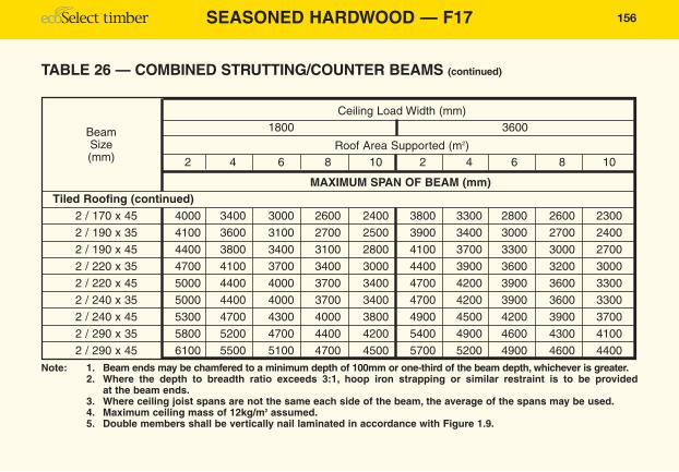
TABLE 26 — COMBINED STRUTTING/COUNTER BEAMS (continued)
156
Ceiling Load Width (mm)1800 3600
Roof Area Supported (m2)2 4 6 8 10 2 4 6 8 10
MAXIMUM SPAN OF BEAM (mm)Tiled Roofing (continued)
2 / 170 x 45 4000 3400 3000 2600 2400 3800 3300 2800 2600 2300
2 / 190 x 35 4100 3600 3100 2700 2500 3900 3400 3000 2700 2400
2 / 190 x 45 4400 3800 3400 3100 2800 4100 3700 3300 3000 2700
2 / 220 x 35 4700 4100 3700 3400 3000 4400 3900 3600 3200 3000
2 / 220 x 45 5000 4400 4000 3700 3400 4700 4200 3900 3600 3300
2 / 240 x 35 5000 4400 4000 3700 3400 4700 4200 3900 3600 3300
2 / 240 x 45 5300 4700 4300 4000 3800 4900 4500 4200 3900 3700
2 / 290 x 35 5800 5200 4700 4400 4200 5400 4900 4600 4300 4100
2 / 290 x 45 6100 5500 5100 4700 4500 5700 5200 4900 4600 4400
BeamSize(mm)
Note: 1. Beam ends may be chamfered to a minimum depth of 100mm or one-third of the beam depth, whichever is greater.2. Where the depth to breadth ratio exceeds 3:1, hoop iron strapping or similar restraint is to be provided
at the beam ends.3. Where ceiling joist spans are not the same each side of the beam, the average of the spans may be used.4. Maximum ceiling mass of 12kg/m2 assumed.5. Double members shall be vertically nail laminated in accordance with Figure 1.9.

"A"
"B"
Strutting Beam Span
Sheet Roofing Tiled Roofing
Roof Area Supported (m2)2 4 6 8 10 2 4 6 8 10
MAXIMUM SPAN OF ROOF STRUTTING BEAM (mm)2 / 120 x 35 3600 3000 2500 2200 2000 2800 2000 1700 1400 1300
2 / 120 x 45 4100 3400 2800 2500 2200 3100 2300 1900 1600 1500
2 / 140 x 35 4600 3700 3100 2700 2400 3500 2500 2100 1800 1600
2 / 140 x 45 5100 4200 3500 3100 2800 3900 2800 2300 2000 1800
2 / 170 x 35 5700 4900 4100 3600 3200 4500 3400 2800 2400 2200
2 / 170 x 45 6200 5400 4600 4000 3600 5000 3800 3100 2700 2400
2 / 190 x 35 6400 5600 4800 4200 3800 5300 3900 3300 2800 2500
2 / 190 x 45 7000 6100 5300 4700 4300 5800 4400 3700 3200 2900
2 / 220 x 35 7200 6400 5700 5100 4600 6200 4800 4000 3500 3100
2 / 220 x 45 7200 6800 6200 5600 5200 6500 5300 4500 3900 3500
2 / 240 x 35 7200 7000 6400 5800 5300 6800 5500 4600 4000 3600
TABLE 27 — STRUTTING BEAMS
BeamSize(mm)
Refer to Fig. 1.13.17 for detailed diagram
157SEASONED HARDWOOD — F17

SEASONED HARDWOOD — F17
TABLE 27 — STRUTTING BEAMS (continued)
158
Sheet Roofing Tiled Roofing
Roof Area Supported (m2)2 4 6 8 10 2 4 6 8 10
MAXIMUM SPAN OF ROOF STRUTTING BEAM (mm)2 / 240 x 45 7200 7200 6800 6300 5900 7200 6000 5100 4500 4000
2 / 290 x 35 7200 7200 7200 7000 6600 7200 6700 6000 5300 4700
2 / 290 x 45 7200 7200 7200 7200 7000 7200 7200 6400 5900 5300
BeamSize(mm)
Note: 1. The allowable spans are based on the support of roof loads only.2. Hoop iron strapping or similar restraint is to be provided at mid-span and at the beam ends.3. Beam ends may be chamfered to a minimum depth of 100mm or one-third of the beam depth, whichever is
greater.4. A minimum initial clearance of 25mm shall be provided at mid-span between the underside of the strutting
beam and the tops of the ceiling joist, ceiling lining or ceiling battens as appropriate.5. Double members shall be vertically nail laminated in accordance with Figure 1.9.

TABLE 33 — BEARERS SUPPORTING TWO STOREYLOADBEARING WALLSLower Floor Load Width – 900mm or 1800mm
Refer to Fig. 1.13.23 for detailed diagram
171SEASONED HARDWOOD — F17
Sheet Roofing Tiled Roofing
Roof Load Width (RLW) mm
1500 2100 4500 7500 1500 2100 4500 7500
MAXIMUM SPAN OF BEARER (mm)UPPER FLOOR LOAD WIDTH 1800mmSingle Span
2 / 85 x 30 1000 1000 NS NS NS NS NS NS
2 / 85 x 40 1100 1100 1000 1000 1100 1000 NS NS
2 / 90 x 35 1100 1100 1000 1000 1100 1000 NS NS
2 / 90 x 45 1200 1200 1100 1100 1200 1100 1000 NS
2 / 120 x 35 1500 1500 1400 1300 1400 1400 1300 1100
2 / 120 x 45 1700 1600 1500 1400 1600 1500 1400 1300
Continuous Spans2 / 85 x 30 1400 1400 1300 1200 1300 1300 1200 1000
2 / 85 x 40 1500 1500 1400 1300 1500 1400 1300 1200
Bearer Size
Depth x Breadth(mm)

SEASONED HARDWOOD — F17
TABLE 33 — BEARERS SUPPORTING TWO STOREY LOADBEARING WALLSLower Floor Load Width – 900mm or 1800mm (continued)
172
Sheet Roofing Tiled Roofing
Roof Load Width (RLW) mm
1500 2100 4500 7500 1500 2100 4500 7500
MAXIMUM SPAN OF BEARER (mm)UPPER FLOOR LOAD WIDTH 1800mm (continued)Continuous Spans
2 / 90 x 35 1500 1500 1400 1300 1500 1400 1300 12002 / 90 x 45 1700 1700 1600 1500 1600 1600 1400 1300
2 / 120 x 35 2100 2000 1900 1800 2000 1900 1700 16002 / 120 x 45 2300 2200 2100 2000 2200 2100 1900 1700
UPPER FLOOR LOAD WIDTH 3600mmSingle Span
2 / 85 x 30 NS NS NS NS NS NS NS NS2 / 85 x 40 1000 1000 NS NS NS NS NS NS2 / 90 x 35 1000 1000 NS NS NS NS NS NS2 / 90 x 45 1100 1100 1000 1000 1000 1000 NS NS
2 / 120 x 35 1300 1300 1300 1200 1300 1300 1200 11002 / 120 x 45 1500 1400 1400 1300 1400 1400 1300 1200
Bearer Size
Depth x Breadth(mm)

173
TABLE 33 — BEARERS SUPPORTING TWO STOREY LOADBEARING WALLSLower Floor Load Width – 900mm or 1800mm (continued)
SEASONED HARDWOOD — F17
Sheet Roofing Tiled Roofing
Roof Load Width (RLW) mm
1500 2100 4500 7500 1500 2100 4500 7500
MAXIMUM SPAN OF BEARER (mm)UPPER FLOOR LOAD WIDTH 3600mm (continued)Continuous Spans
2 / 85 x 30 1200 1200 1200 1100 1200 1100 1000 NS2 / 85 x 40 1300 1300 1300 1200 1300 1300 1200 11002 / 90 x 35 1400 1300 1300 1200 1300 1300 1200 11002 / 90 x 45 1500 1500 1400 1300 1400 1400 1300 1200
2 / 120 x 35 1800 1800 1700 1700 1800 1700 1600 14002 / 120 x 45 2000 2000 1900 1800 1900 1900 1700 1600
Bearer Size
Depth x Breadth(mm)
NS = Not suitable.Note: 1. Table assumes a maximum flooring mass of 40kg/m2.
2. Footing and stump details shall be determined in conjunction with the selection of bearers, refer AS1684.3. Double members shall be vertically nail laminated in accordance with Figure 1.9.

Lower FLWSee Page 9
Upper FLWSee Page 9
Upper Floor Load Width (mm)
3600 4800 6000
MAXIMUM SPAN OF BEARER (mm)LOWER FLOOR LOAD WIDTH 1800mmSingle Span
2 / 85 x 30 NS NS NS
2 / 85 x 40 1000 NS NS
2 / 90 x 35 1000 NS NS
2 / 90 x 45 1100 1000 1000
2 / 120 x 35 1400 1300 1200
2 / 120 x 45 1500 1400 1300
Continuous Spans2 / 85 x 30 1300 1200 1100
2 / 85 x 40 1400 1300 1200
2 / 90 x 35 1400 1300 1200
TABLE 35 — FLOOR BEARERS (Lower Storey of Two StoreySupporting Upper and Lower Floor Loads Only)
Joist Size
Depth x Breadth(mm)
Refer to Fig. 1.13.24 for detailed diagram
177SEASONED HARDWOOD — F17
SEASONED HARDWOOD — F17
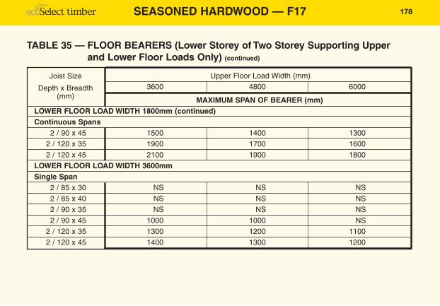
TABLE 35 — FLOOR BEARERS (Lower Storey of Two Storey Supporting Upperand Lower Floor Loads Only) (continued)
178
Upper Floor Load Width (mm)
3600 4800 6000
MAXIMUM SPAN OF BEARER (mm)LOWER FLOOR LOAD WIDTH 1800mm (continued)Continuous Spans
2 / 90 x 45 1500 1400 1300
2 / 120 x 35 1900 1700 1600
2 / 120 x 45 2100 1900 1800
LOWER FLOOR LOAD WIDTH 3600mmSingle Span
2 / 85 x 30 NS NS NS
2 / 85 x 40 NS NS NS
2 / 90 x 35 NS NS NS
2 / 90 x 45 1000 1000 NS
2 / 120 x 35 1300 1200 1100
2 / 120 x 45 1400 1300 1200
Joist Size
Depth x Breadth(mm)

179
TABLE 35 — FLOOR BEARERS (Lower Storey of Two Storey Supporting Upperand Lower Floor Loads Only) (continued)
SEASONED HARDWOOD — F17
Upper Floor Load Width (mm)
3600 4800 6000
MAXIMUM SPAN OF BEARER (mm)LOWER FLOOR LOAD WIDTH 3600mm (continued)Continuous Spans
2 / 85 x 30 1100 1000 NS
2 / 85 x 40 1300 1200 1100
2 / 90 x 35 1200 1200 1100
2 / 90 x 45 1400 1300 1200
2 / 120 x 35 1700 1600 1500
2 / 120 x 45 1900 1800 1700
Joist Size
Depth x Breadth(mm)
Note: 1. Table assumes a maximum flooring mass of 40kg/m2.2. Double members shall be vertically nail laminated in accordance with Figure 1.9.

SEASONED HARDWOOD — F17
Lintel
UpperFloor Joist
Top Plate (lower storey)
Stud At Side Of Opening(lower storey)
Stud(lower storey)
Lintel Span
Roo f Load
Width RLW
Sheet Roofing Tiled Roofing
Roof Load Width (RLW) mm
1500 2100 4500 7500 1500 2100 4500 7500
MAXIMUM SPAN OF LINTEL (mm)UPPER FLOOR LOAD WIDTH 1800mm
90 x 35 1200 1200 1100 1000 1100 1100 900 800
90 x 45 1300 1200 1100 1000 1200 1100 1000 900
120 x 35 1500 1500 1400 1200 1400 1300 1200 1000
120 x 45 1700 1600 1500 1300 1500 1400 1300 1100
140 x 35 1800 1700 1600 1400 1600 1500 1300 1200
140 x 45 1900 1900 1700 1600 1800 1700 1500 1300
170 x 35 2100 2100 1900 1700 2000 1900 1600 1400
170 x 45 2300 2200 2100 1900 2100 2000 1800 1600
190 x 35 2400 2300 2100 1900 2200 2100 1800 1600
190 x 45 2600 2500 2300 2100 2400 2300 2000 1700
TABLE 47/48 — LINTELS Lower Storey Loadbearing Walls
Lintel Size
Depth x Breadth(mm)
Refer to Fig. 1.13.30 for detailed diagram
180

181
Sheet Roofing Tiled Roofing
Roof Load Width (RLW) mm
1500 2100 4500 7500 1500 2100 4500 7500
MAXIMUM SPAN OF LINTEL (mm)UPPER FLOOR LOAD WIDTH 1800mm (continued)
2 / 190 x 35 3000 2900 2600 2400 2700 2600 2300 2000220 x 35 2700 2700 2400 2200 2500 2400 2100 1800220 x 45 3000 2900 2600 2400 2700 2600 2300 2000
2 / 220 x 35 3300 3200 3000 2800 3100 3000 2600 2300240 x 35 3000 2900 2700 2400 2800 2600 2300 2000240 x 45 3200 3100 2900 2600 3000 2800 2500 2200
2 / 240 x 35 3500 3400 3200 3000 3300 3200 2900 25002 / 240 x 45 3700 3700 3400 3200 3500 3400 3100 2800
290 x 45 3600 3600 3300 3100 3400 3300 3000 2700•2 / 290 x 45 4300 4200 3900 3700 4000 3900 3500 3200
UPPER FLOOR LOAD WIDTH 3600mm90 x 35 1000 1000 900 900 1000 900 800 80090 x 45 1100 1100 1000 900 1000 1000 900 800
TABLE 47/48 — LINTELS Lower Storey Loadbearing Walls (continued)
Lintel Size
Depth x Breadth(mm)
SEASONED HARDWOOD — F17
SEASONED HARDWOOD — F17
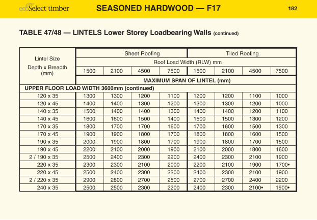
TABLE 47/48 — LINTELS Lower Storey Loadbearing Walls (continued)
182
Sheet Roofing Tiled Roofing
Roof Load Width (RLW) mm
1500 2100 4500 7500 1500 2100 4500 7500
MAXIMUM SPAN OF LINTEL (mm)UPPER FLOOR LOAD WIDTH 3600mm (continued)
120 x 35 1300 1300 1200 1100 1200 1200 1100 1000120 x 45 1400 1400 1300 1200 1300 1300 1200 1000140 x 35 1500 1400 1400 1300 1400 1400 1200 1100140 x 45 1600 1600 1500 1400 1500 1500 1300 1200170 x 35 1800 1700 1700 1600 1700 1600 1500 1300170 x 45 1900 1900 1800 1700 1800 1800 1600 1500190 x 35 2000 1900 1800 1700 1900 1800 1700 1500190 x 45 2200 2100 2000 1900 2100 2000 1800 1600
2 / 190 x 35 2500 2400 2300 2200 2400 2300 2100 1900220 x 35 2300 2300 2100 2000 2200 2100 1900 1700•220 x 45 2500 2400 2300 2200 2400 2300 2100 1900
2 / 220 x 35 2900 2800 2700 2500 2700 2700 2400 2200240 x 35 2500 2500 2300 2200 2400 2300 2100• 1900•
Lintel Size
Depth x Breadth(mm)

183
Sheet Roofing Tiled Roofing
Roof Load Width (RLW) mm
1500 2100 4500 7500 1500 2100 4500 7500
MAXIMUM SPAN OF LINTEL (mm)UPPER FLOOR LOAD WIDTH 3600mm (continued)
240 x 45 2700 2700 2500 2400 2600 2500 2300 21002 / 240 x 35 3100 3100 2900 2700 3000 2900 2600 24002 / 240 x 45 3300 3200 3100 3000 3200 3100 2800 2600
290 x 45 3200 3200 3000 2900• 3100 3000 2700• 2500➤
2 / 290 x 45 3800 3700 3600 3400 3700 3600 3300 3100
TABLE 47/48 — LINTELS Lower Storey Loadbearing Walls (continued)
Bearer Size
Depth x Breadth(mm)
SEASONED HARDWOOD — F17
Note: 1. Minimum bearing length = 35 mm at end supports.• Additional 5 mm bearing length required.➤ Additional 10 mm bearing length required.
2. These lintels are not designed to support concentrated loads.3. Lintels to internal wall openings supporting floor loads only shall be sized as bearers.4. Double members shall be vertically nail laminated in accordance with Figure 1.9.

184
(Blank)


![e-beam [F17] LVL is a direct substitute for F17 hardwood at competitive … · 2017-08-29 · e-beam+ [F17] LVL is a direct substitute for F17 hardwood at competitive prices and is](https://static.fdocuments.net/doc/165x107/5f43fc49ddb8f2221b04a783/e-beam-f17-lvl-is-a-direct-substitute-for-f17-hardwood-at-competitive-2017-08-29.jpg)