MEI CASHFLOW 7000 SERIES CHANGE MANAGERThe CF7000 fitted to your vending machine incorporates the...
65
MEI, 2004 Page 1 Rev: G1 MEI CASHFLOW ® 7000 SERIES CHANGE MANAGER ENGINEERS HANDBOOK
Transcript of MEI CASHFLOW 7000 SERIES CHANGE MANAGERThe CF7000 fitted to your vending machine incorporates the...

MEI, 2004 Page 1 Rev: G1
MEI CASHFLOW® 7000 SERIESCHANGE MANAGER
ENGINEERS HANDBOOK
CashFlow 7000 Series Engineers Guide
MEI, 2004 Page 2 Rev: G1
MEI Cashflow® 7000 Series Change Manager Engineers Handbook
This edition (August 2004) Printed in the United Kingdom.
Internet: http://www.meiglobal.com
For further information on editions in other languages please contact your regional salesrepresentative.
© , Mars, Inc., 2003. All rights reserved
Except as permitted under the relevant local legislation, no part of this publication may becopied, transmitted, transcribed, or distributed in any form or by any means, or stored in adatabase or retrieval system, or translated in any language (natural or computer), withoutthe prior written permission of MEI.
Mars®, MEI Cashflow® and the MEI device are registered trademarks.
MEI reserves the right to change the product or the product specifications at any time. Whileevery effort has been made to ensure that the information in this publication is accurate, MEIdisclaims any liability for any direct or indirect losses (howsoever caused) arising out of useor reliance on this information.
This document does not necessarily imply product availability.
Note: Your product may differ slightly from some of the illustrations in this document.
CashFlow 7000 Series Engineers Guide
MEI, 2004 Page 3 Rev: G1
DECLARATION OF CONFORMITYNational & International Standards ConformanceCashFlow® 7000 Series products operate at Safety Extra Low Voltage Level (SELV) asdefined in IEC335/EN60335 ‘Safety of Household and Similar Appliances’. They may bedesigned into equipment complying with IEC335/EN60335 or IEC950/EN60950 ‘Safety ofInformation Technology Equipment’. CashFlow® 7000 Series products are of Class 3 construction.
Rated Operating VoltageThe operating voltage of a CashFlow® 7000 Series is stated on the label attached to theproduct. It must not be used with any power source other than that indicated.
Dangerous EnvironmentsThe CashFlow® 7000 Series must not be operated in the presence of flammable gasses,fumes or water.
ABOUT THIS HANDBOOKThe CF7000 fitted to your vending machine incorporates the very latest developments inautomatic payment systems technology. It provides high standards of security and reliabilitythat has become the hallmark of MEI products.
This Engineers Handbook compliments your product training and provides you with theinformation you need to support the day-to-day use of your CF7000. The Handbook has six sections:Product Overview and Range – provides an overview of how the CF7000 is configured andinformation about the modules with which you will be concerned.Installation and Power Up – describes how the CF7000 should be installed and how topower up and set up your changer.Change Management – explains the new functions concerned with payout and auto floatconfigurations. Configuration Options – explains how to configure the CF7000 for the following options:
• Cassette – how to change the cassette type.• Float – how to set the float style.• Coins – how to enable and inhibit coins.• Tokens - how to enable, teach and delete tokens.• Prices – how to set prices.• Interface Setup – how to configure your interface.• Peripherals – how to connect different peripherals.• Audit – how to connect and retrieve audit information.
Maintenance – explains the routine cleaning requirements.Troubleshooting – explains how problems are automatically identified and tells you whatcorrective action you can take.

CashFlow 7000 Series Engineers Guide
MEI, 2004 Page 4 Rev: G1
CashFlow 7000 Series Engineers Guide
MEI, 2004 Page 5 Rev: G1
CONTENTSDECLARATION OF CONFORMITY .............................................................................................................. 3
NATIONAL & INTERNATIONAL STANDARDS CONFORMANCE .............................................................................. 3RATED OPERATING VOLTAGE............................................................................................................................. 3DANGEROUS ENVIRONMENTS ............................................................................................................................. 3
ABOUT THIS HANDBOOK............................................................................................................................... 3
INSTALLATION ................................................................................................................................................. 8
PREPARING FOR INSTALLATION........................................................................................................................... 8INSTALLING THE CF7000.................................................................................................................................... 9ALIGNMENT CHECKS ........................................................................................................................................ 10CABLE CONNECTION......................................................................................................................................... 10CONNECTING PERIPHERALS .............................................................................................................................. 11
PRODUCT OVERVIEW................................................................................................................................... 12
CF7000 OVERVIEW .......................................................................................................................................... 12Product Range: ..........................................................................................................................................................13Machine Interfaces Available:...................................................................................................................................13Machine Peripherals Available: ................................................................................................................................14
POWERING UP AND CONFIGURING THE CF7000................................................................................................ 15INITIAL CHECKS & TESTS ................................................................................................................................. 16
Reject Lever: .............................................................................................................................................................16Display & LED’s: .....................................................................................................................................................16Language Setting:......................................................................................................................................................16Dispenser (Park Arms): .............................................................................................................................................16Vend:.........................................................................................................................................................................17
HOW TO USE THE DISPLAY & SELECT MENUS .................................................................................... 18
MAN MACHINE INTERFACE (MMI) FUNCTIONS................................................................................................ 18Basic LED Operation: ...............................................................................................................................................18General MMI Button Operation: ...............................................................................................................................19General LED Light Codes.........................................................................................................................................19Amber LED Light Codes ..........................................................................................................................................19General Mode Button Operation: ..............................................................................................................................20How to Access the Set Up Menu:..............................................................................................................................20Message Waiting Icon:..............................................................................................................................................21
MENU STRUCTURE............................................................................................................................................ 22Service Mode Menu Options:....................................................................................................................................22Set-Up Mode Menu Options: ....................................................................................................................................23
CHANGE MANAGEMENT ............................................................................................................................. 24
INTRODUCTION ................................................................................................................................................. 24FLOAT TO LEVEL............................................................................................................................................... 24
What is Float to Level? .............................................................................................................................................24FLOAT TO VALUE.............................................................................................................................................. 24
What is Float to Value?.............................................................................................................................................24AUTO-FLOAT .................................................................................................................................................... 25
What is Auto Float? ..................................................................................................................................................25SNAPSHOT FLOAT ............................................................................................................................................. 25
What is Snapshot Float? ............................................................................................................................................25PAYOUT MIX..................................................................................................................................................... 26
Large Coins: ..............................................................................................................................................................26Small Coins: ..............................................................................................................................................................26Change Machine: ......................................................................................................................................................26
LOW CHANGE ................................................................................................................................................... 27OPTIMISE CHANGE............................................................................................................................................ 27CASSETTE WIZARD ........................................................................................................................................... 27

CashFlow 7000 Series Engineers Guide
MEI, 2004 Page 6 Rev: G1
CRITICAL BUSINESS STATISTICS (CBS) ............................................................................................................ 28Operation Time Period ..............................................................................................................................................28CBS Yearly Report Details .......................................................................................................................................28
CONFIGURATION OPTIONS ........................................................................................................................ 29
CASSETTE ......................................................................................................................................................... 29Changing Cassette Configuration..............................................................................................................................29Cassette Teach...........................................................................................................................................................29Cassette Calibration ..................................................................................................................................................31
FLOAT............................................................................................................................................................... 32Setting the Float Style ...............................................................................................................................................32Configuring the Float ................................................................................................................................................32Using Snapshot Float ................................................................................................................................................33
COINS................................................................................................................................................................ 34Acceptance Modes ....................................................................................................................................................34
Setting Acceptance Mode.....................................................................................................................................34Inhibit or Enable Coins .............................................................................................................................................34
With coin sample..................................................................................................................................................34Without coin sample.............................................................................................................................................35
TOKENS............................................................................................................................................................. 35Token Types..............................................................................................................................................................35
Value Token .........................................................................................................................................................35Vend Token ..........................................................................................................................................................35Reject Token ........................................................................................................................................................35Slug ......................................................................................................................................................................35
Enable a Pre-programmed Token..............................................................................................................................36Token Teach..............................................................................................................................................................36Delete a Token ..........................................................................................................................................................37
PRICES .............................................................................................................................................................. 37Price Holding: ...........................................................................................................................................................38Prices Held in Machine: ............................................................................................................................................38Prices Held in Changer:.............................................................................................................................................38Setting Prices.............................................................................................................................................................39
INTERFACE SETUP ............................................................................................................................................. 40Decimal Point Position (DPP):..................................................................................................................................40Coin Scaling Factor:..................................................................................................................................................40MDB .........................................................................................................................................................................41
Level 2 or 3 ..........................................................................................................................................................41Optimise Change (level 2)....................................................................................................................................41Float Coins (Hide/report) .....................................................................................................................................41Coin Counts..........................................................................................................................................................41Country.................................................................................................................................................................41
EXEC ........................................................................................................................................................................42Price Holding........................................................................................................................................................42Max Credit............................................................................................................................................................42Price Display ........................................................................................................................................................42Vend Type............................................................................................................................................................42Overpay and Overpay Amount.............................................................................................................................42Escrow Return ......................................................................................................................................................42Vend Time Limit ..................................................................................................................................................43
BDV ..........................................................................................................................................................................43Award Discount....................................................................................................................................................43Trigger Discount...................................................................................................................................................43Max Change .........................................................................................................................................................43Link Master ID .....................................................................................................................................................43Exact Change Equation ........................................................................................................................................43
PERIPHERALS .................................................................................................................................................... 44Card or Key System (Exec and BDV Only)..............................................................................................................44
Cashless Revaluation............................................................................................................................................44Discounted Price...................................................................................................................................................44
Bill Validator (Exec and BDV Only) ........................................................................................................................44Highest Value.......................................................................................................................................................44
AUDIT ............................................................................................................................................................... 45Audit Types...............................................................................................................................................................45
CashFlow 7000 Series Engineers Guide
MEI, 2004 Page 7 Rev: G1
How to take a Visual Audit ..................................................................................................................................45How to take an Audit using a Printer ...................................................................................................................46How to setup a printer ticket ................................................................................................................................47How to take an Audit using a DEX device...........................................................................................................48
MAINTENANCE ............................................................................................................................................... 49
CLEANING......................................................................................................................................................... 49Safety ........................................................................................................................................................................49What to use................................................................................................................................................................49Cleaning the Acceptor module ..................................................................................................................................49
Cash Path..............................................................................................................................................................49Accept Gate and Routing Gates............................................................................................................................49Reject Path ...........................................................................................................................................................50
Dispenser Arms and Guides ......................................................................................................................................50CHANGING THE DISCRIMINATOR....................................................................................................................... 52CHANGING THE CONTROL PCB......................................................................................................................... 53CHANGING THE ACOUSTIC MODULE. ................................................................................................................ 55CHANGING THE DISPENSER. .............................................................................................................................. 56ADDING LOOMS. ............................................................................................................................................... 58REMOVING LOOMS............................................................................................................................................ 59REPLACING COIN TUBES. .................................................................................................................................. 60UPDATING SOFTWARE....................................................................................................................................... 62
PRODUCT SUPPORT....................................................................................................................................... 63
AUSTRIA .................................................................................................................................................................63BELGIUM / NETHERLANDS / LUXEMBURG.....................................................................................................63FINLAND .................................................................................................................................................................63FRANCE...................................................................................................................................................................63GERMANY...............................................................................................................................................................63GREAT BRITAIN ....................................................................................................................................................64GREECE ...................................................................................................................................................................64IRELAND .................................................................................................................................................................64ISRAEL.....................................................................................................................................................................64ITALY.......................................................................................................................................................................64PORTUGAL .............................................................................................................................................................65SPAIN .......................................................................................................................................................................65
CashFlow 7000 Series Engineers Guide
MEI, 2004 Page 8 Rev: G1
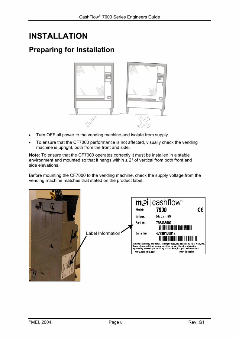
INSTALLATIONPreparing for Installation
• Turn OFF all power to the vending machine and isolate from supply.
• To ensure that the CF7000 performance is not affected, visually check the vendingmachine is upright, both from the front and side.
Note: To ensure that the CF7000 operates correctly it must be installed in a stableenvironment and mounted so that it hangs within ± 2° of vertical from both front andside elevations.
Before mounting the CF7000 to the vending machine, check the supply voltage from thevending machine matches that stated on the product label.
Label Information
CashFlow 7000 Series Engineers Guide
MEI, 2004 Page 9 Rev: G1
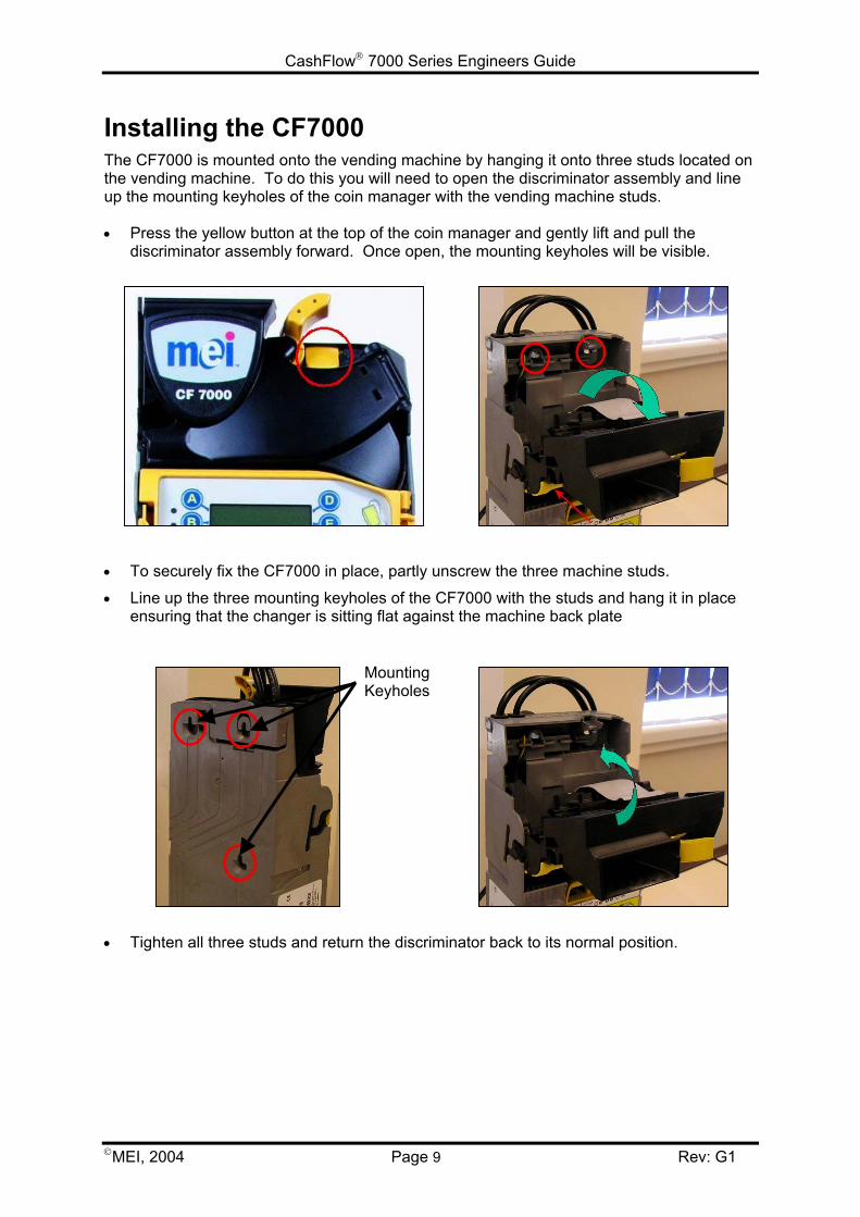
Installing the CF7000The CF7000 is mounted onto the vending machine by hanging it onto three studs located onthe vending machine. To do this you will need to open the discriminator assembly and lineup the mounting keyholes of the coin manager with the vending machine studs.
• Press the yellow button at the top of the coin manager and gently lift and pull thediscriminator assembly forward. Once open, the mounting keyholes will be visible.
• To securely fix the CF7000 in place, partly unscrew the three machine studs.
• Line up the three mounting keyholes of the CF7000 with the studs and hang it in placeensuring that the changer is sitting flat against the machine back plate
• Tighten all three studs and return the discriminator back to its normal position.
MountingKeyholes
CashFlow 7000 Series Engineers Guide
MEI, 2004 Page 10 Rev: G1
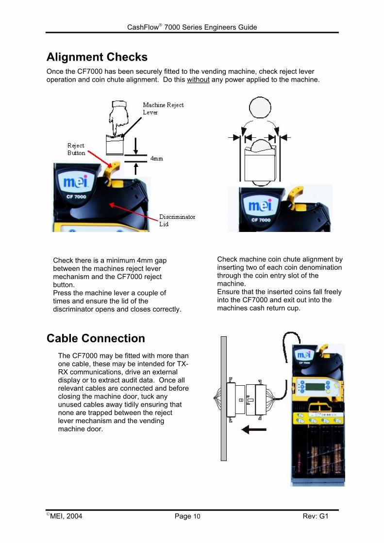
Alignment ChecksOnce the CF7000 has been securely fitted to the vending machine, check reject leveroperation and coin chute alignment. Do this without any power applied to the machine.
Cable Connection
Check there is a minimum 4mm gapbetween the machines reject levermechanism and the CF7000 rejectbutton.Press the machine lever a couple oftimes and ensure the lid of thediscriminator opens and closes correctly.
Check machine coin chute alignment byinserting two of each coin denominationthrough the coin entry slot of themachine.Ensure that the inserted coins fall freelyinto the CF7000 and exit out into themachines cash return cup.
The CF7000 may be fitted with more thanone cable, these may be intended for TX-RX communications, drive an externaldisplay or to extract audit data. Once allrelevant cables are connected and beforeclosing the machine door, tuck anyunused cables away tidily ensuring thatnone are trapped between the rejectlever mechanism and the vendingmachine door.
CashFlow 7000 Series Engineers Guide
MEI, 2004 Page 11 Rev: G1
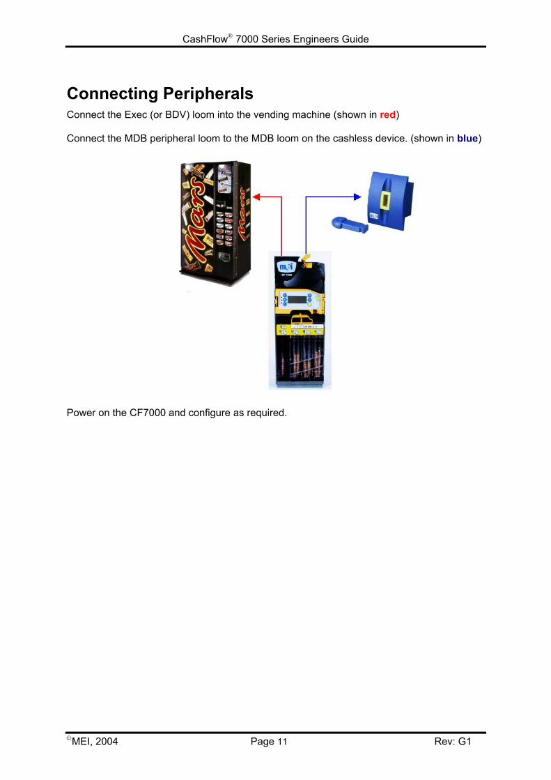
Connecting PeripheralsConnect the Exec (or BDV) loom into the vending machine (shown in red)
Connect the MDB peripheral loom to the MDB loom on the cashless device. (shown in blue)
Power on the CF7000 and configure as required.
CashFlow 7000 Series Engineers Guide
MEI, 2004 Page 12 Rev: G1
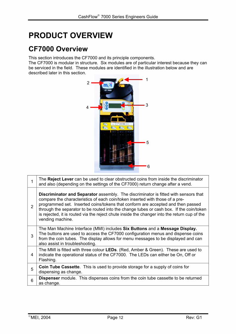
PRODUCT OVERVIEWCF7000 OverviewThis section introduces the CF7000 and its principle components.The CF7000 is modular in structure. Six modules are of particular interest because they canbe serviced in the field. These modules are identified in the illustration below and aredescribed later in this section.
1 The Reject Lever can be used to clear obstructed coins from inside the discriminatorand also (depending on the settings of the CF7000) return change after a vend.
2
Discriminator and Separator assembly. The discriminator is fitted with sensors thatcompare the characteristics of each coin/token inserted with those of a pre-programmed set. Inserted coins/tokens that conform are accepted and then passedthrough the separator to be routed into the change tubes or cash box. If the coin/tokenis rejected, it is routed via the reject chute inside the changer into the return cup of thevending machine.
3
The Man Machine Interface (MMI) includes Six Buttons and a Message Display.The buttons are used to access the CF7000 configuration menus and dispense coinsfrom the coin tubes. The display allows for menu messages to be displayed and canalso assist in troubleshooting.
4The MMI is fitted with three colour LEDs. (Red, Amber & Green). These are used toindicate the operational status of the CF7000. The LEDs can either be On, Off orFlashing.
5 Coin Tube Cassette. This is used to provide storage for a supply of coins fordispensing as change.
6 Dispenser module. This dispenses coins from the coin tube cassette to be returnedas change.
4 3
5
6
21
CashFlow 7000 Series Engineers Guide
MEI, 2004 Page 13 Rev: G1
Product Range:
MEI CASHFLOW™ 7900
With the highest coin capacity in the market and five active tubes the CF7900 virtuallyeliminates exact change situations on even the most demanding sites. However, byconstantly monitoring the coin flow it can also work to reduce the cash tied up in the tubeswhere the vend price or coin throughput allows a more efficient level in each tube, evenadvising on a more suitable tube configuration when appropriate.
Machine Interfaces Available:
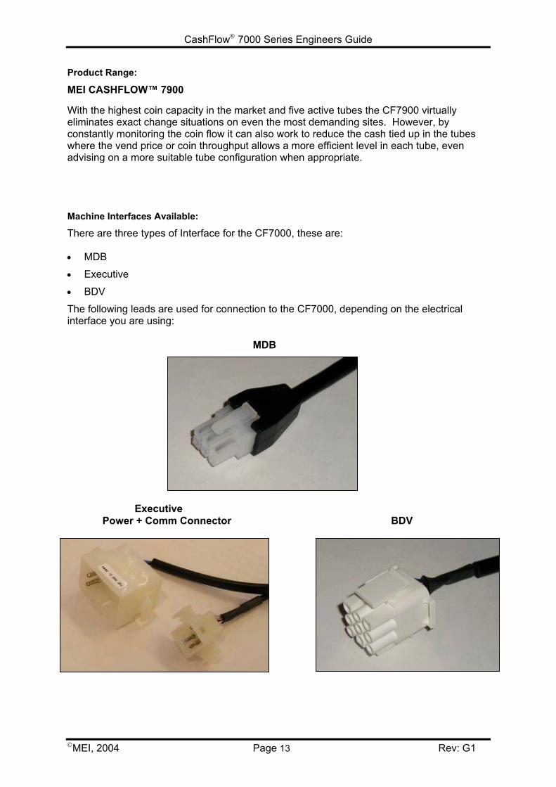
There are three types of Interface for the CF7000, these are:
• MDB
• Executive
• BDV
The following leads are used for connection to the CF7000, depending on the electricalinterface you are using:
MDB
Executive Power + Comm Connector BDV
CashFlow 7000 Series Engineers Guide
MEI, 2004 Page 14 Rev: G1
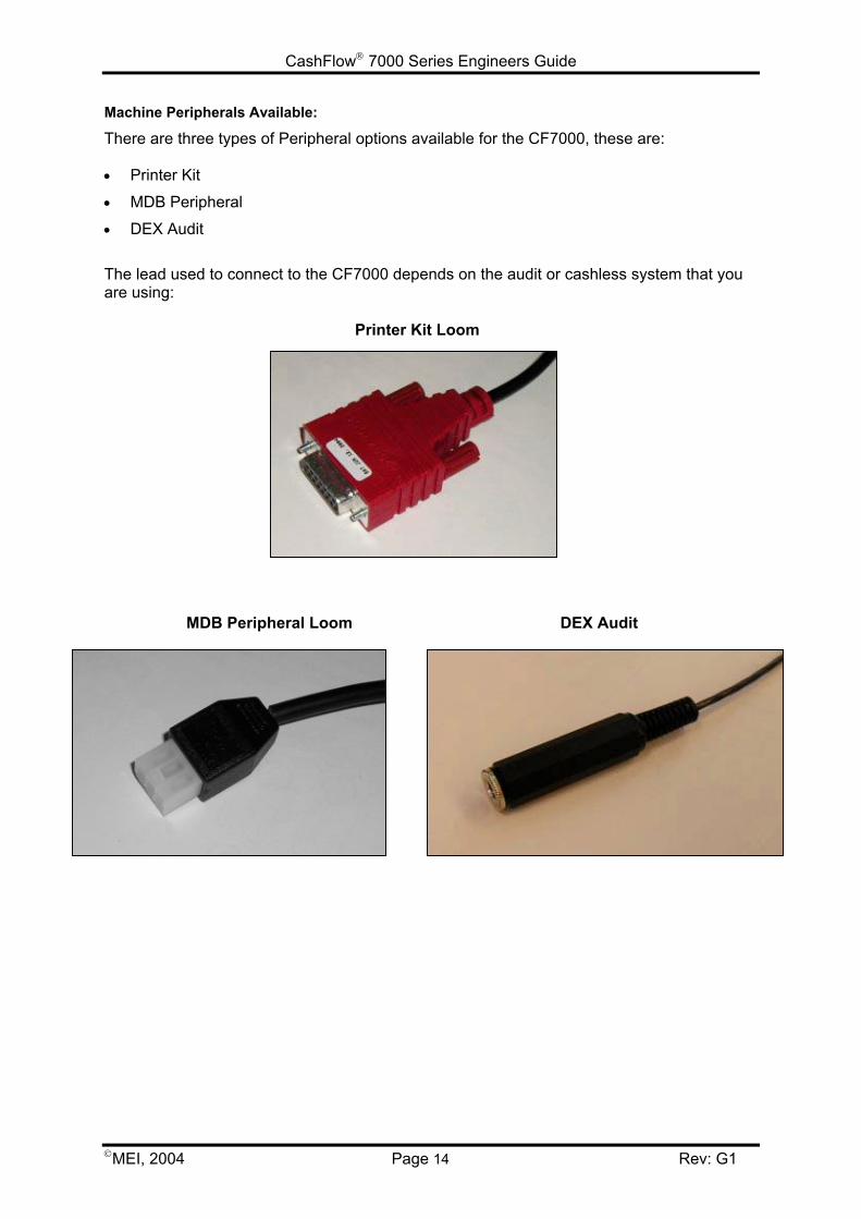
Machine Peripherals Available:
There are three types of Peripheral options available for the CF7000, these are:
• Printer Kit
• MDB Peripheral
• DEX Audit
The lead used to connect to the CF7000 depends on the audit or cashless system that youare using:
Printer Kit Loom
MDB Peripheral Loom DEX Audit
CashFlow 7000 Series Engineers Guide
MEI, 2004 Page 15 Rev: G1
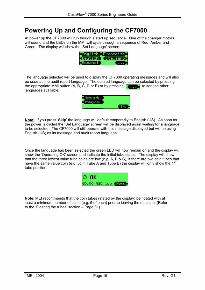
Powering Up and Configuring the CF7000At power up the CF7000 will run though a start up sequence. One of the changer motorswill sound and the LEDs on the MMI will cycle through a sequence of Red, Amber andGreen. The display will show the ‘Set Language’ screen:
The language selected will be used to display the CF7000 operating messages and will alsobe used as the audit report language. The desired language can be selected by pressingthe appropriate MMI button (A, B, C, D or E) or by pressing to see the otherlanguages available.
Note: If you press ‘Skip’ the language will default temporarily to English (US). As soon asthe power is cycled the ‘Set Language’ screen will be displayed again waiting for a languageto be selected. The CF7000 will still operate with this message displayed but will be usingEnglish (US) as its message and audit report language.
Once the language has been selected the green LED will now remain on and the display willshow the ‘Operating OK’ screen and indicate the initial tube status. The display will showthat the three lowest value tube coins are low (e.g. A, B & C), if there are two coin tubes thathave the same value coin (e.g. 5c in Tube A and Tube E) the display will only show the 1st
tube position.
Note: MEI recommends that the coin tubes (stated by the display) be floated with atleast a minimum number of coins (e.g. 5 of each) prior to leaving the machine. (Referto the ‘Floating the tubes’ section – Page 31).
CashFlow 7000 Series Engineers Guide
MEI, 2004 Page 16 Rev: G1
Initial Checks & TestsIt is advisable to run a few minor checks / tests after the installation, to ensure that theCF7000 is going to operate correctly and thus reducing unexpected and unnecessaryengineer call outs.
Reject Lever:
Operate the machine reject lever a couple of times to check the installation procedures havebeen followed correctly. Problems with the reject lever operation can result in coinacceptance issues and increased chances of coins jamming in the changer.
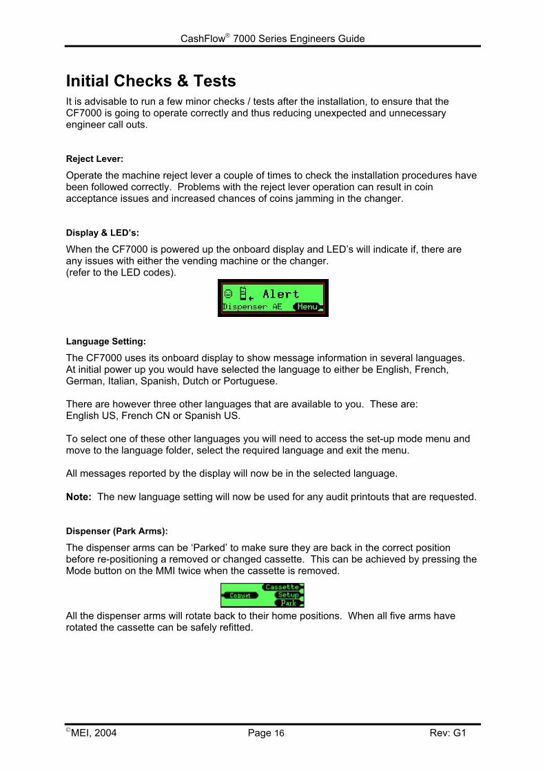
Display & LED’s:
When the CF7000 is powered up the onboard display and LED’s will indicate if, there areany issues with either the vending machine or the changer. (refer to the LED codes).
Language Setting:
The CF7000 uses its onboard display to show message information in several languages.At initial power up you would have selected the language to either be English, French,German, Italian, Spanish, Dutch or Portuguese.
There are however three other languages that are available to you. These are:English US, French CN or Spanish US.
To select one of these other languages you will need to access the set-up mode menu andmove to the language folder, select the required language and exit the menu.
All messages reported by the display will now be in the selected language.
Note: The new language setting will now be used for any audit printouts that are requested.
Dispenser (Park Arms):
The dispenser arms can be ‘Parked’ to make sure they are back in the correct positionbefore re-positioning a removed or changed cassette. This can be achieved by pressing theMode button on the MMI twice when the cassette is removed.
All the dispenser arms will rotate back to their home positions. When all five arms haverotated the cassette can be safely refitted.
CashFlow 7000 Series Engineers Guide
MEI, 2004 Page 17 Rev: G1
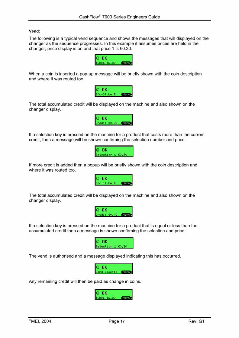
Vend:
The following is a typical vend sequence and shows the messages that will displayed on thechanger as the sequence progresses. In this example it assumes prices are held in thechanger, price display is on and that price 1 is €0.30.
When a coin is inserted a pop-up message will be briefly shown with the coin descriptionand where it was routed too.
The total accumulated credit will be displayed on the machine and also shown on thechanger display.
If a selection key is pressed on the machine for a product that costs more than the currentcredit, then a message will be shown confirming the selection number and price.
If more credit is added then a popup will be briefly shown with the coin description andwhere it was routed too.
The total accumulated credit will be displayed on the machine and also shown on thechanger display.
If a selection key is pressed on the machine for a product that is equal or less than theaccumulated credit then a message is shown confirming the selection and price.
The vend is authorised and a message displayed indicating this has occurred.
Any remaining credit will then be paid as change in coins.
CashFlow 7000 Series Engineers Guide
MEI, 2004 Page 18 Rev: G1
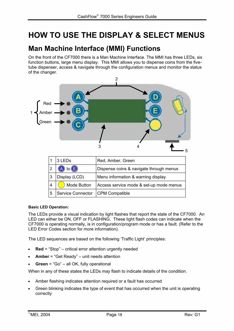
HOW TO USE THE DISPLAY & SELECT MENUSMan Machine Interface (MMI) FunctionsOn the front of the CF7000 there is a Man Machine Interface. The MMI has three LEDs, sixfunction buttons, large menu display. This MMI allows you to dispense coins from the five-tube dispenser, access & navigate through the configuration menus and monitor the statusof the changer.
1 3 LEDs Red, Amber, Green
2 to Dispense coins & navigate through menus
3 Display (LCD) Menu information & warning display
4 Mode Button Access service mode & set-up mode menus
5 Service Connector CPM Compatible
Basic LED Operation:
The LEDs provide a visual indication by light flashes that report the state of the CF7000. AnLED can either be ON, OFF or FLASHING. These light flash codes can indicate when theCF7000 is operating normally, is in configuration/program mode or has a fault. (Refer to theLED Error Codes section for more information).
The LED sequences are based on the following ‘Traffic Light’ principles:
• Red = “Stop” – critical error attention urgently needed
• Amber = “Get Ready” – unit needs attention
• Green = “Go” – all OK, fully operational
When in any of these states the LEDs may flash to indicate details of the condition.
• Amber flashing indicates attention required or a fault has occurred
• Green blinking indicates the type of event that has occurred when the unit is operatingcorrectly
A E
1
2
45
Red
Amber
Green
3
CashFlow 7000 Series Engineers Guide
MEI, 2004 Page 19 Rev: G1
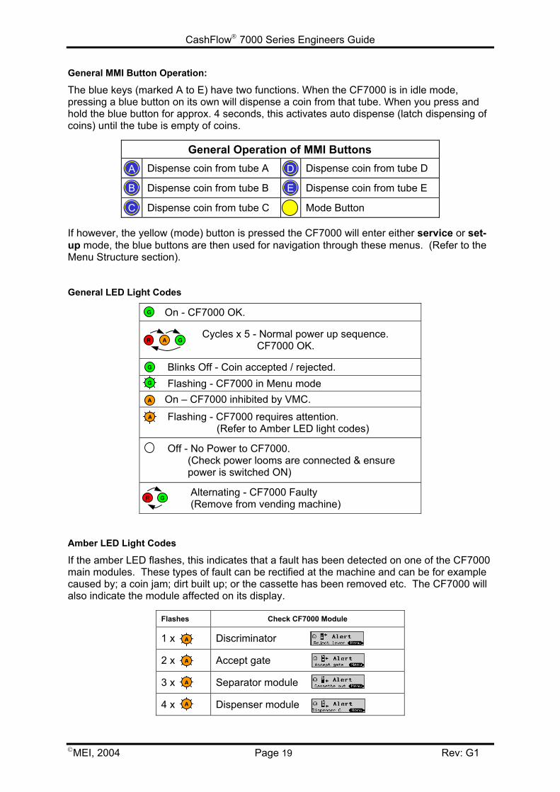
General MMI Button Operation:
The blue keys (marked A to E) have two functions. When the CF7000 is in idle mode,pressing a blue button on its own will dispense a coin from that tube. When you press andhold the blue button for approx. 4 seconds, this activates auto dispense (latch dispensing ofcoins) until the tube is empty of coins.
General Operation of MMI ButtonsDispense coin from tube A Dispense coin from tube D
Dispense coin from tube B Dispense coin from tube E
Dispense coin from tube C Mode Button
If however, the yellow (mode) button is pressed the CF7000 will enter either service or set-up mode, the blue buttons are then used for navigation through these menus. (Refer to theMenu Structure section).
General LED Light Codes
On - CF7000 OK.
Cycles x 5 - Normal power up sequence. CF7000 OK.
Blinks Off - Coin accepted / rejected. Flashing - CF7000 in Menu mode On – CF7000 inhibited by VMC.
Flashing - CF7000 requires attention. (Refer to Amber LED light codes)
Off - No Power to CF7000. (Check power looms are connected & ensure power is switched ON)
Alternating - CF7000 Faulty (Remove from vending machine)
Amber LED Light Codes
If the amber LED flashes, this indicates that a fault has been detected on one of the CF7000main modules. These types of fault can be rectified at the machine and can be for examplecaused by; a coin jam; dirt built up; or the cassette has been removed etc. The CF7000 willalso indicate the module affected on its display.
Flashes Check CF7000 Module
1 x Discriminator
2 x Accept gate
3 x Separator module
4 x Dispenser module
A
B
C
D
E
A
G
A
GAR
R G
G
A
A
A
A
G
CashFlow 7000 Series Engineers Guide
MEI, 2004 Page 20 Rev: G1
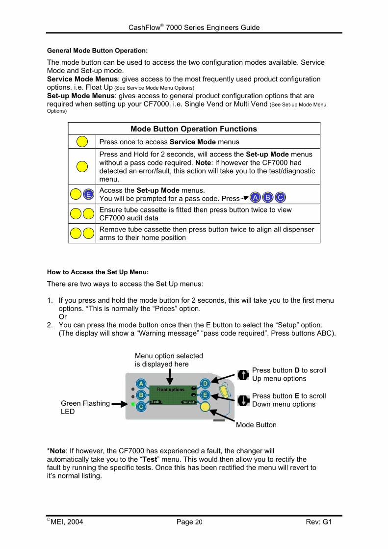
General Mode Button Operation:
The mode button can be used to access the two configuration modes available. ServiceMode and Set-up mode.Service Mode Menus: gives access to the most frequently used product configurationoptions. i.e. Float Up (See Service Mode Menu Options)Set-up Mode Menus: gives access to general product configuration options that arerequired when setting up your CF7000. i.e. Single Vend or Multi Vend (See Set-up Mode MenuOptions)
Mode Button Operation FunctionsPress once to access Service Mode menus
Press and Hold for 2 seconds, will access the Set-up Mode menuswithout a pass code required. Note: If however the CF7000 haddetected an error/fault, this action will take you to the test/diagnosticmenu.Access the Set-up Mode menus.You will be prompted for a pass code. PressEnsure tube cassette is fitted then press button twice to viewCF7000 audit dataRemove tube cassette then press button twice to align all dispenserarms to their home position
How to Access the Set Up Menu:
There are two ways to access the Set Up menus:
1. If you press and hold the mode button for 2 seconds, this will take you to the first menuoptions. *This is normally the “Prices” option.Or
2. You can press the mode button once then the E button to select the “Setup” option.(The display will show a “Warning message” “pass code required”. Press buttons ABC).
*Note: If however, the CF7000 has experienced a fault, the changer willautomatically take you to the “Test” menu. This would then allow you to rectify thefault by running the specific tests. Once this has been rectified the menu will revert toit’s normal listing.
E A B C
Menu option selectedis displayed here
Press button D to scrollUp menu options
Press button E to scrollDown menu options
Mode Button
Green FlashingLED
CashFlow 7000 Series Engineers Guide
MEI, 2004 Page 21 Rev: G1
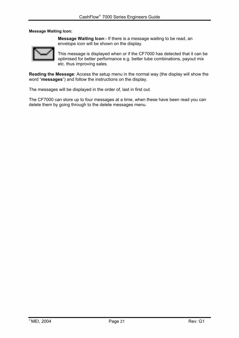
Message Waiting Icon:
Message Waiting Icon:- If there is a message waiting to be read, anenvelope icon will be shown on the display.
This message is displayed when or if the CF7000 has detected that it can beoptimised for better performance e.g. better tube combinations, payout mixetc. thus improving sales.
Reading the Message: Access the setup menu in the normal way (the display will show theword “messages”) and follow the instructions on the display.
The messages will be displayed in the order of, last in first out.
The CF7000 can store up to four messages at a time, when these have been read you candelete them by going through to the delete messages menu.

CashFlow 7000 Series Engineers Guide
MEI, 2004 Page 22 Rev: G1
Menu StructureThe menu structure on the CF7000 is made out of two folder levels. The main menu folder(as shown below) and under this the sub menu folders.
Service Mode Menu Options:
Service Mode Menu gives access to the most frequently used product configuration options.Press the mode button once to access this. The structure is as shown here.
LANGUAGE
PRICES
FLOAT OPTIONS
CHANGE MGMT
MACHINE OPTIONS
COIN CONFIG
AUDIT CONFIG
CASHLESS CONFIG
BANKNOTE CONFIG
GENERAL
ERROR LOG
TEST
Service Mode Menu Starts from Here
Menu Option Selected
Press button D - Scrolls UP the menus
Press button E – Scrolls Down the menus
EXAMPLE: - How to set the language
1. Press the ‘Mode’ button once
2. Press button ‘E’ to select ‘Setup’
3. Enter pass code, Press ‘A’’B’’C’
4. Press button ‘D’ to scroll up the menu untilthe display shows ‘Language’
5. Press ‘Select’ then ‘Edit’
6. Use button ‘D’ or ‘E’ to scroll to the requiredlanguage
7. Select ‘OK’
8. Select ‘Back’ and ‘Back’ again to save andexit your setting
MESSAGES Only if messages available
CashFlow 7000 Series Engineers Guide
MEI, 2004 Page 23 Rev: G1
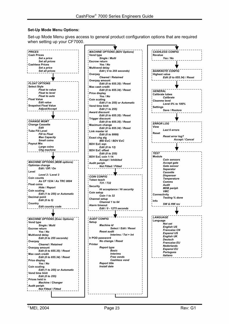
Set-Up Mode Menu Options:
Set-up Mode Menu gives access to general product configuration options that are requiredwhen setting up your CF7000.
MACHINE OPTIONS (BDV Options) Vend type
Single / Multi Escrow return
Yes / No Multivend delay
Edit ( 0 to 255 seconds) Overpay
Cleared / Retained Overpay amount
Edit (0 to 655.35) / Reset Max cash credit
Edit (0 to 655.34) / Reset Price display
Yes / No Coin scaling
Edit (1 to 255) or Automatic Vend time limit
Edit (1 to 255) Award discount
Edit (0 to 655.35) / Reset Trigger discount
Edit (0 to 655.35) / Reset Maximum change
Edit (0 to 655.34) / Reset Link master id
Edit (0 to 9999) Exact chg alg
MEI ExC / BDV ExC BDV ExC eqn
Edit (0 to 12) BDV ExC offset
Edit (0 to 255) BDV ExC coin 1-14
Accept / Inhibited Audit periph
Not Fitted / Fitted
COIN CONFIG Token teach
T31 / T32 Security
Hi acceptance / Hi security Coin setup
Coin 1 to 32 Channel setup
Channel 1 to 64 Alarm timeout
Edit / 0 - 1275 seconds
CASHLESS CONFIG Revalue
Yes / No
TEST Module
Coin sensorsAccept gateGate sensorSeparatorCassetteDispenserTemperatureCommsAuditMDB periphVMC
ConnectivityTesting % done
InfoSW & HW rev
ERROR LOG View
Last 6 errors Reset
Reset error log?Accept / Cancel
GENERAL Calibrate tubes
Calibrate Cleanme level
Level 0% to 100% Settings
Save / Restore
BANKNOTE CONFIG Highest value
Edit (0 to 655.34) / Reset
LANGUAGE Language
Not setEnglish USFrancaise CNEspanol USEnglish UKDeutschFrancaise EUNederlandsEspanol EUPortuguesItaliano
FLOAT OPTIONS Select Style
Float to valueFloat to levelFloat to auto
Float ValueEdit value
Snapshot Float ValueAdjust/Accept
PRICES Cash Prices
Set a priceSet all prices
Cashless PricesSet a priceSet all prices
MACHINE OPTIONS (MDB options) Optimize change
Edit / Off / On Level
Level 2 / Level 3 Coin counts
As CF 1234 / As TRC 0004 Float coins
Hide / Report Coin scaling
Edit (1 to 255) or Automatic Decimal point
Edit (0 to 5) Country
Edit country code
CHANGE MGMT Change Cassette
Edit Tube Fill Level
Fill to FloatMax CapacitySmall coins
Payout MixLarge coinsChg machine
MACHINE OPTIONS (Exec Options) Vend type
Single / Multi Escrow return
Yes / No Multivend delay
Edit (0 to 255 seconds) Overpay
Cleared / Retained Overpay amount
Edit (0 to 655.35) / Reset Max cash credit
Edit (0 to 655.34) / Reset Price display
Yes / No Coin scaling
Edit (1 to 255) or Automatic Vend time limit
Edit (0 to 255) Prices held in
Machine / Changer Audit periph
Not Fitted / Fitted
AUDIT CONFIG Setup
Machine idSelect / Edit / Reset
Reset auditInterims / Tot + Int
Ir POD passwordNo change / Reset
PrinterReport type
BasicInterimsFree vendsCashless vend
Report titleInstall date
CashFlow 7000 Series Engineers Guide
MEI, 2004 Page 24 Rev: G1
CHANGE MANAGEMENTIntroductionThe CF7000 has many new features that allow the product to be called a change managerrather than a change giver. In addition to the high capacity five tube cassette the newfeatures enable the CF7000 to more effectively manage the operation of the unit and tooptimise the float levels of the machine and the change payout. These new features providean opportunity for the operator to optimise the vend revenue by minimising the amount oftime the unit operates in exact change mode.
Float to LevelWhat is Float to Level?
Each tube can be filled to a specific level, after which the coins are routed to the cash box.This is the traditional float style. To set this up, you enter the total number of coins of thattype that you want to store in the changer. This level applies to all tubes holding the sametype of coin. For example, if the level was 30, and the coins were stored in three tubes,there will be 10 coins in each tube.
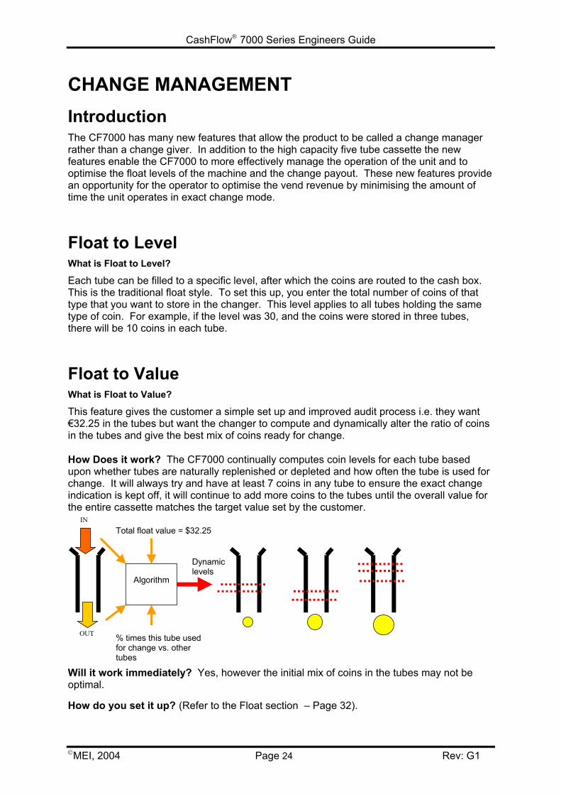
Float to ValueWhat is Float to Value?
This feature gives the customer a simple set up and improved audit process i.e. they want€32.25 in the tubes but want the changer to compute and dynamically alter the ratio of coinsin the tubes and give the best mix of coins ready for change.
How Does it work? The CF7000 continually computes coin levels for each tube basedupon whether tubes are naturally replenished or depleted and how often the tube is used forchange. It will always try and have at least 7 coins in any tube to ensure the exact changeindication is kept off, it will continue to add more coins to the tubes until the overall value forthe entire cassette matches the target value set by the customer.
IN
OUT % times this tube usedfor change vs. othertubes
Total float value = $32.25
Algorithm
Dynamiclevels
Will it work immediately? Yes, however the initial mix of coins in the tubes may not beoptimal.
How do you set it up? (Refer to the Float section – Page 32).
CashFlow 7000 Series Engineers Guide
MEI, 2004 Page 25 Rev: G1
Auto-FloatWhat is Auto Float?
The aim of this feature is to have no settings for the customer to set up or compute and thechanger to operate with the minimum amount of money in the tubes but ensuring the exactchange light is rarely lit and that change is available for vends.
How Does it work? Auto float uses probability calculations to reduce the chance of theexact change light coming on and monitors prices and whether bills are used to determinethe fewest number of coins with the best optimal mix.
• Auto Float is based on the last 64 coins in.• Auto Float is calculated as a ratio of coins in and coins out.
Will it work immediately? Yes, however it requires some time to gather information onhow the tubes are being used, during this time it will run the tubes at their maximum level toensure there is always enough change.
• The consumer will notice no difference.• Auto float will ask for a number of coins inserted to meet the auto float level. Any
coins inserted once the float level has been achieved will be rejected – no overfillis possible.
• If a coin tube has more coins in it than is required by the auto float the tube willdispense coins until the correct calculated level is reached.
• There is no notification what the current auto float level is.• The float level will change depending on the ratio of coins accepted and coins
dispensed.• Auto float only manages coins to cash box - it will stop coins being routed to the
cash box if they are needed to keep the exact change light off.• Float Up and Float Down do not operate in auto float mode.
How do you Set-up Auto Float? (Refer to the Float section - Page 32).
Snapshot Float
What is Snapshot Float?
When this function is triggered it takes a "snapshot" of the current cassette and uses that tosetup the float settings.
How Does it work? The snapshot feature allows the operator to manually fill the coincassette tubes to either a predetermined level or value and then save them as theoperational float settings.
Will it work immediately? Yes, but the snapshot feature is only available when the unit isset to ‘Float to Level’ or ‘Float to Value’.
How do you use Snapshot Float? (Refer to the Float section - Page 33).
CashFlow 7000 Series Engineers Guide
MEI, 2004 Page 26 Rev: G1
Payout MixThis feature determines the mix of coins that the customer will receive back once their vendis complete. There are three available settings with the CF7000.
• Large Coins • Small Coins• Change Machine
Large Coins:
This is the best option for the customer with fewer coins returned. This feature uses thesame "weighted best change" function as the CF690 however the activation level is fixed at15. It tries to prevent coin levels in a tube dropping below the trigger level and will use othercoin denominations in preference.
Small Coins:
This is a new feature and is the best option for the operator. It is designed to keep the twolowest value tube coins out of the cash box. This is done by preferentially paying out anycoins that are close to the maximum level from the two lowest value tubes. The trigger levelis set to 88% of the maximum fill level. The decision process of which coins to pay out has 3steps.
1) Paying any coins from the lowest value tube that is above the threshold.2) Paying any coins from the second lowest value tube that is above the threshold.3) Paying the remainder of credit by the "least coins algorithm", as described above.
Notes:1. The trigger level is set by integer arithmetic. Threshold = max fill level - (max fill / (2/3))2. The maximum fill level changes depending upon change management tube fill level. Ifthis option is set to ‘MAX CAPACITY’ then maximum fill will equal the predefined max filllevel for the coin / tube combination. If the option is set to ‘Fill to Float’ then the maximum filllevel will be set to the float levels determined by the Float.
Change Machine:
This is a new feature. Designed to pay out one coin from each tube value allowingmaximum flexibility for re-insertion. The change value is achieved by starting with one coinfrom the lowest value tube and one from the next value tube, up to and including the highestvalue tube. Then paying the rest with the minimum number of coins. The decision processregarding coins to pay out has 2 steps.
1) Paying one coin from each tube if value not greater than remaining credit, starting fromthe lowest value tube.2) Paying the remainder of credit by the "least coins algorithm" as above.
Notes:1. For all three algorithms they will work out which coins to pay, then pay them out insequence from tube "E" to "A".2. Multiple tubes of the same coin are treated as if they are one long tube with the individualtube counts and max fill levels added together.3. With multiple tubes of the same coin the highest lettered tube will be emptied first.
CashFlow 7000 Series Engineers Guide
MEI, 2004 Page 27 Rev: G1
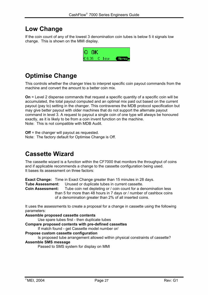
Low ChangeIf the coin count of any of the lowest 3 denomination coin tubes is below 5 it signals lowchange. This is shown on the MMI display.
Optimise ChangeThis controls whether the changer tries to interpret specific coin payout commands from themachine and convert the amount to a better coin mix.
On = Level 2 dispense commands that request a specific quantity of a specific coin will beaccumulated, the total payout computed and an optimal mix paid out based on the currentpayout (pay to) setting in the changer. This contravenes the MDB protocol specification butmay give better payout with older machines that do not support the alternate payoutcommand in level 3. A request to payout a single coin of one type will always be honouredexactly, as it is likely to be from a coin invent function on the machine.Note: This is not compatible with MDB Audit.
Off = the changer will payout as requested.Note: The factory default for Optimise Change is Off.
Cassette WizardThe cassette wizard is a function within the CF7000 that monitors the throughput of coinsand if applicable recommends a change to the cassette configuration being used.It bases its assessment on three factors:
Exact Change: Time in Exact Change greater than 15 minutes in 28 days.Tube Assessment: Unused or duplicate tubes in current cassette.Coin Assessment: Tube coin net depleting or / coin count for a denomination less
than 5 for more than 48 hours in 7 days or / number of cashbox coins of a denomination greater than 2% of all inserted coins.
It uses the assessments to create a proposal for a change in cassette using the followingparameters:Assemble proposed cassette contents
Use spare tubes first - then duplicate tubesCompare proposed contents with pre-defined cassettes
If match found - get Cassette model number or/Propose custom cassette configuration
Is proposed tube arrangement allowed within physical constraints of cassette?Assemble SMS message
Passed to SMS system for display on MMI
CashFlow 7000 Series Engineers Guide
MEI, 2004 Page 28 Rev: G1
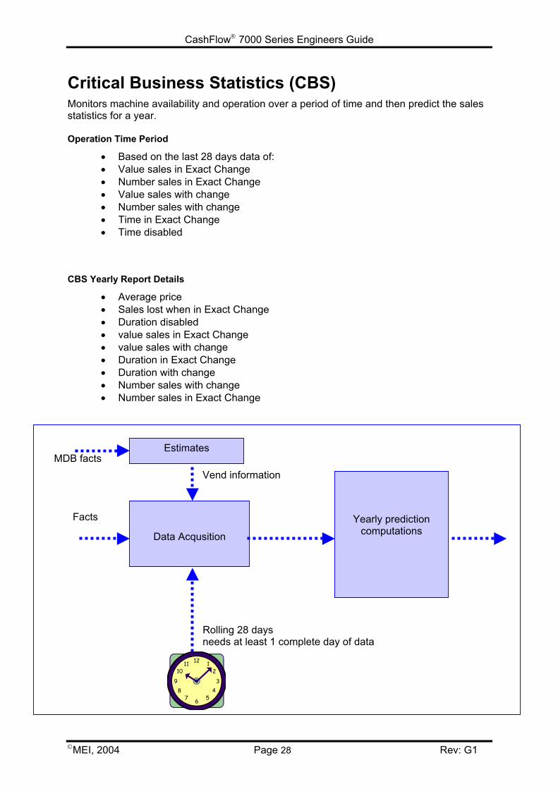
Critical Business Statistics (CBS)Monitors machine availability and operation over a period of time and then predict the salesstatistics for a year.
Operation Time Period
• Based on the last 28 days data of:• Value sales in Exact Change• Number sales in Exact Change• Value sales with change• Number sales with change• Time in Exact Change• Time disabled
CBS Yearly Report Details
• Average price• Sales lost when in Exact Change• Duration disabled• value sales in Exact Change• value sales with change• Duration in Exact Change• Duration with change• Number sales with change• Number sales in Exact Change
Yearly predictioncomputationsData Acqusition
Rolling 28 daysneeds at least 1 complete day of data
Facts
Estimates
Vend informationMDB facts

CashFlow 7000 Series Engineers Guide
MEI, 2004 Page 29 Rev: G1
CONFIGURATION OPTIONSCassetteChanging Cassette Configuration
Remove the fitted cassette and press the yellow mode button once. The display will showthe following message:
Press the D (Cassette) and using the cassette option table below enter the required two digitcode by pressing the corresponding letters on the MMI (A to E).
The screen will change to show the cassette payout for the option you have just entered.Press the yellow mode (Accept) button if this is correct.
Fit the new cassette with the selected payout option to the unit.
The CF7000 can store up to 6 cassette options in its internal memory and is supplied withonly the fitted option stored. Therefore, if this is the first time the chosen payout option hasbeen selected on the unit it will need to be calibrated. Once this option and up to four morehave been calibrated the cassette can then be changed between these 6 payout optionswithout having to be re-calibrated.
If the “Cassette calibration required” screen is displayed press the yellow Mode button.
You will then be asked to “Check cassette xx is empty”. Once confirmed, press the yellowMode button (Calibrate) - the unit will now calibrate the new cassette and on completionpress the Mode button (OK).
The display will now show that the tube contents are Low and inform you which tubes needto be filled to turn off exact change.
The cassette model is clearly printed on the front of the cassette. The following cassettesare available for European use:
Key Code Tube A Tube B Tube C Tube D Tube EAA 5c 10c 50c 20c 5cAB 1c 10c 50c 2c 5cAC 5c 10c 50c 20c €1AD 5c 10c 50c 10c €1AE 5c 10c 50c 10c 5cBA 10c 10c 50c 10c €1BB 10c 10c 50c 20c €1BC 20c 10c 50c €1 €2BD €1 - 50c €1 €2BE €1 - 50c €2 €2CA 1c 10c 50c €1 5c
Cassette Teach
CashFlow 7000 Series Engineers Guide
MEI, 2004 Page 30 Rev: G1
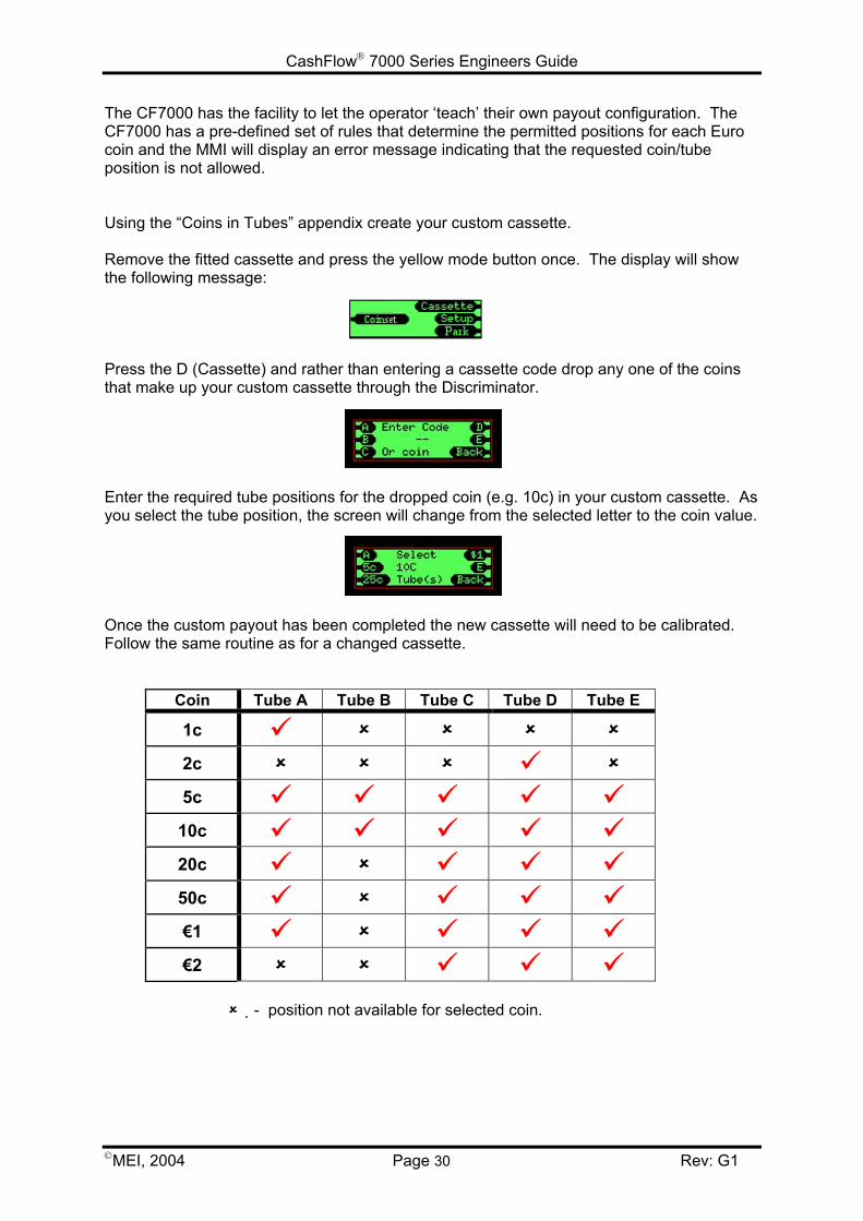
The CF7000 has the facility to let the operator ‘teach’ their own payout configuration. TheCF7000 has a pre-defined set of rules that determine the permitted positions for each Eurocoin and the MMI will display an error message indicating that the requested coin/tubeposition is not allowed.
Using the “Coins in Tubes” appendix create your custom cassette.
Remove the fitted cassette and press the yellow mode button once. The display will showthe following message:
Press the D (Cassette) and rather than entering a cassette code drop any one of the coinsthat make up your custom cassette through the Discriminator.
Enter the required tube positions for the dropped coin (e.g. 10c) in your custom cassette. Asyou select the tube position, the screen will change from the selected letter to the coin value.
Once the custom payout has been completed the new cassette will need to be calibrated.Follow the same routine as for a changed cassette.
Coin Tube A Tube B Tube C Tube D Tube E
1c
2c
5c
10c
20c
50c
€1
€2
- position not available for selected coin.
CashFlow 7000 Series Engineers Guide
MEI, 2004 Page 31 Rev: G1
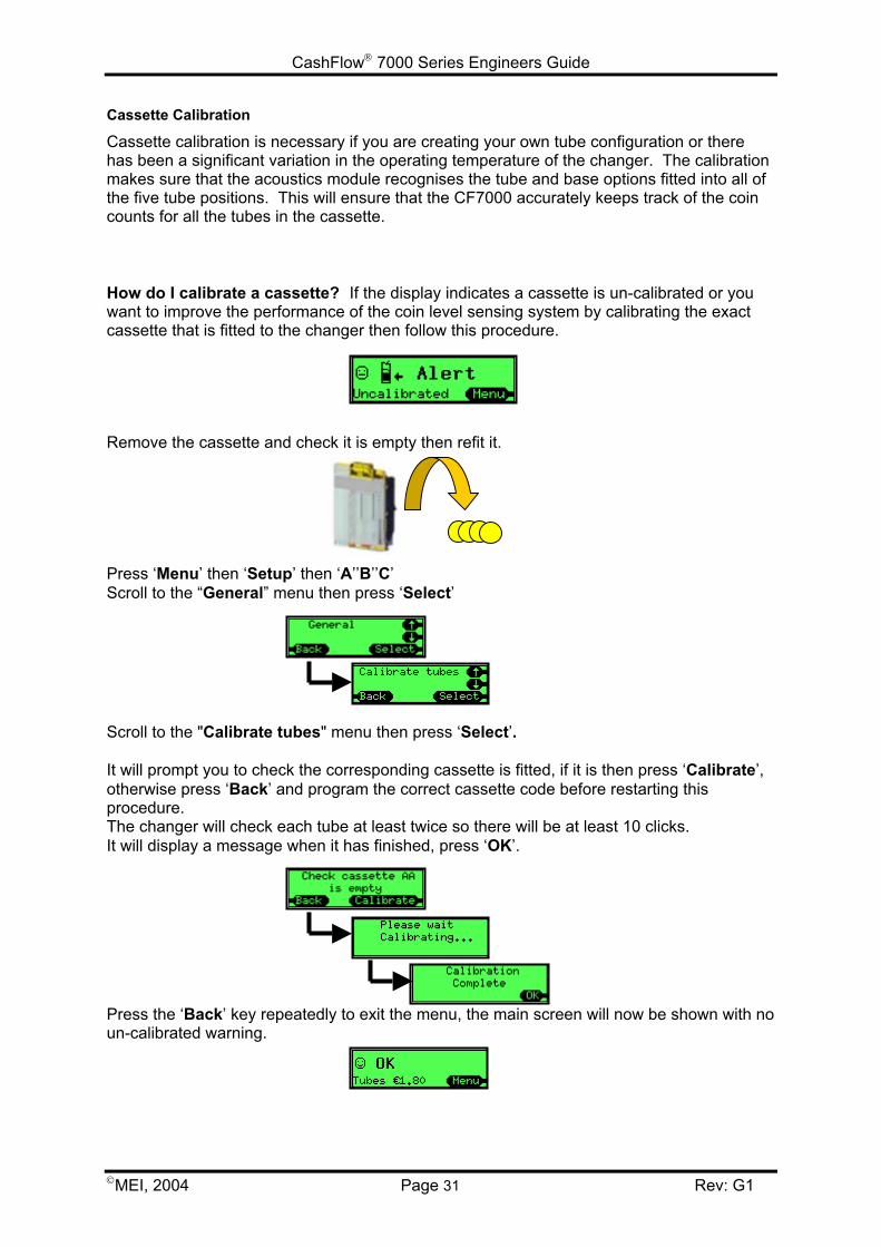
Cassette Calibration
Cassette calibration is necessary if you are creating your own tube configuration or therehas been a significant variation in the operating temperature of the changer. The calibrationmakes sure that the acoustics module recognises the tube and base options fitted into all ofthe five tube positions. This will ensure that the CF7000 accurately keeps track of the coincounts for all the tubes in the cassette.
How do I calibrate a cassette? If the display indicates a cassette is un-calibrated or youwant to improve the performance of the coin level sensing system by calibrating the exactcassette that is fitted to the changer then follow this procedure.
Remove the cassette and check it is empty then refit it.
Press ‘Menu’ then ‘Setup’ then ‘A’’B’’C’Scroll to the “General” menu then press ‘Select’
Scroll to the "Calibrate tubes" menu then press ‘Select’.
It will prompt you to check the corresponding cassette is fitted, if it is then press ‘Calibrate’,otherwise press ‘Back’ and program the correct cassette code before restarting thisprocedure.The changer will check each tube at least twice so there will be at least 10 clicks.It will display a message when it has finished, press ‘OK’.
Press the ‘Back’ key repeatedly to exit the menu, the main screen will now be shown with noun-calibrated warning.

CashFlow 7000 Series Engineers Guide
MEI, 2004 Page 32 Rev: G1
FloatSetting the Float Style
Press ‘Menu’ then ‘Setup’ then ‘A’’B’’C’.Scroll to the “Float Options” then press ‘Select’.
Press ‘Select’ then ‘Edit’.Scroll up or down to the desired option.
Press ‘OK’ then ‘Back’ three times.
Configuring the Float
The float process involves two stages:• Dispense of Excess coins• Addition of insufficient coins
If there is no action to be performed for a stage then it will automatically move onto the nextstage.
Press ‘Menu’ then ‘Float’.
The changer will display a screen indicating it is about to start the float process. Either wait2 seconds or press ‘Next’
If the float style has been set to “Auto Float” then the following message may be flashed onthe display after pressing ‘Float’
As auto float needs to gather information on how the tubes are being used it wants to run thetubes at their maximum level to ensure there is always enough change.
CashFlow 7000 Series Engineers Guide
MEI, 2004 Page 33 Rev: G1
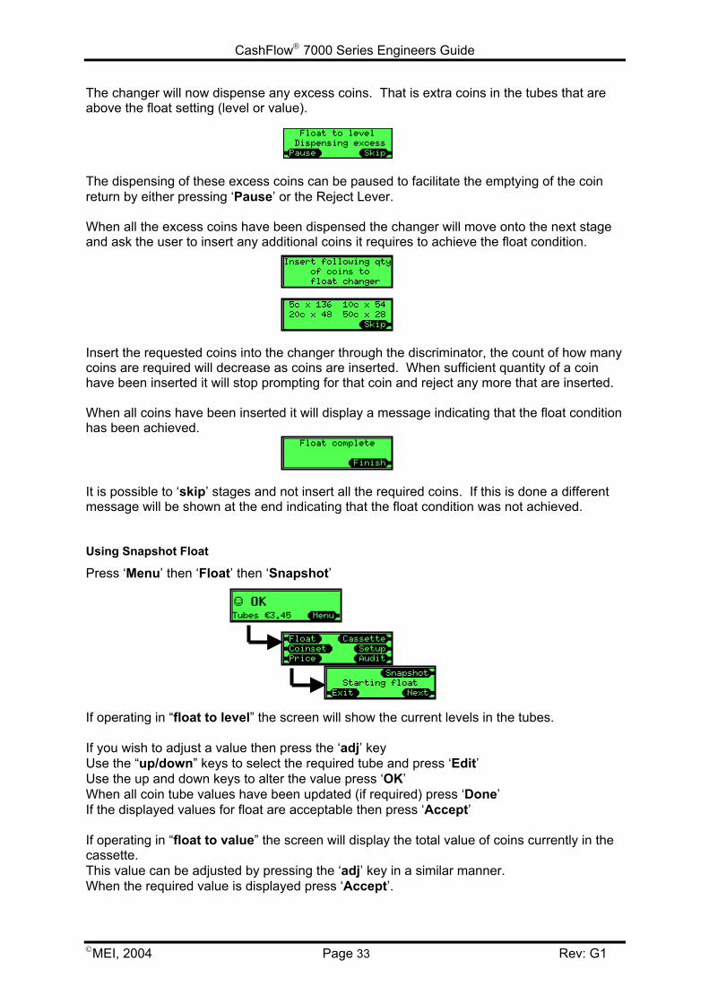
The changer will now dispense any excess coins. That is extra coins in the tubes that areabove the float setting (level or value).
The dispensing of these excess coins can be paused to facilitate the emptying of the coinreturn by either pressing ‘Pause’ or the Reject Lever.
When all the excess coins have been dispensed the changer will move onto the next stageand ask the user to insert any additional coins it requires to achieve the float condition.
Insert the requested coins into the changer through the discriminator, the count of how manycoins are required will decrease as coins are inserted. When sufficient quantity of a coinhave been inserted it will stop prompting for that coin and reject any more that are inserted.
When all coins have been inserted it will display a message indicating that the float conditionhas been achieved.
It is possible to ‘skip’ stages and not insert all the required coins. If this is done a differentmessage will be shown at the end indicating that the float condition was not achieved.
Using Snapshot Float
Press ‘Menu’ then ‘Float’ then ‘Snapshot’
If operating in “float to level” the screen will show the current levels in the tubes.
If you wish to adjust a value then press the ‘adj’ keyUse the “up/down” keys to select the required tube and press ‘Edit’Use the up and down keys to alter the value press ‘OK’When all coin tube values have been updated (if required) press ‘Done’If the displayed values for float are acceptable then press ‘Accept’
If operating in “float to value” the screen will display the total value of coins currently in thecassette. This value can be adjusted by pressing the ‘adj’ key in a similar manner.When the required value is displayed press ‘Accept’.
CashFlow 7000 Series Engineers Guide
MEI, 2004 Page 34 Rev: G1
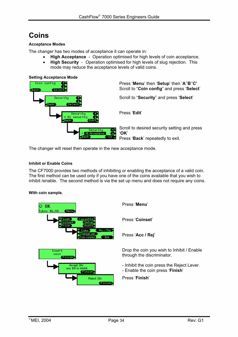
CoinsAcceptance Modes
The changer has two modes of acceptance it can operate in:• High Acceptance - Operation optimised for high levels of coin acceptance.• High Security - Operation optimised for high levels of slug rejection. This
mode may reduce the acceptance levels of valid coins.
Setting Acceptance ModePress ‘Menu’ then ‘Setup’ then ‘A’’B’’C’Scroll to “Coin config” and press ‘Select’
Scroll to “Security” and press ‘Select’
Press ‘Edit’
Scroll to desired security setting and press‘OK’Press ‘Back’ repeatedly to exit.
The changer will reset then operate in the new acceptance mode.
Inhibit or Enable Coins
The CF7000 provides two methods of inhibiting or enabling the acceptance of a valid coin.The first method can be used only if you have one of the coins available that you wish toinhibit /enable. The second method is via the set up menu and does not require any coins.
With coin sample.
Press ‘Menu’
Press ‘Coinset’
Press ‘Acc / Rej’
Drop the coin you wish to Inhibit / Enablethrough the discriminator.
- Inhibit the coin press the Reject Lever.- Enable the coin press ‘Finish’
Press ‘Finish’
CashFlow 7000 Series Engineers Guide
MEI, 2004 Page 35 Rev: G1
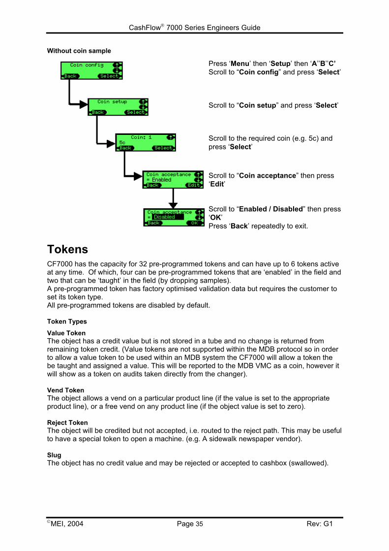
Without coin sample
Press ‘Menu’ then ‘Setup’ then ‘A’’B’’C’Scroll to “Coin config” and press ‘Select’
Scroll to “Coin setup” and press ‘Select’
Scroll to the required coin (e.g. 5c) andpress ‘Select’
Scroll to “Coin acceptance” then press‘Edit’
Scroll to “Enabled / Disabled” then press‘OK’Press ‘Back’ repeatedly to exit.
TokensCF7000 has the capacity for 32 pre-programmed tokens and can have up to 6 tokens activeat any time. Of which, four can be pre-programmed tokens that are ‘enabled’ in the field andtwo that can be ‘taught’ in the field (by dropping samples). A pre-programmed token has factory optimised validation data but requires the customer toset its token type.All pre-programmed tokens are disabled by default.
Token Types
Value TokenThe object has a credit value but is not stored in a tube and no change is returned fromremaining token credit. (Value tokens are not supported within the MDB protocol so in orderto allow a value token to be used within an MDB system the CF7000 will allow a token thebe taught and assigned a value. This will be reported to the MDB VMC as a coin, however itwill show as a token on audits taken directly from the changer).
Vend TokenThe object allows a vend on a particular product line (if the value is set to the appropriateproduct line), or a free vend on any product line (if the object value is set to zero).
Reject TokenThe object will be credited but not accepted, i.e. routed to the reject path. This may be usefulto have a special token to open a machine. (e.g. A sidewalk newspaper vendor).
SlugThe object has no credit value and may be rejected or accepted to cashbox (swallowed).
CashFlow 7000 Series Engineers Guide
MEI, 2004 Page 36 Rev: G1
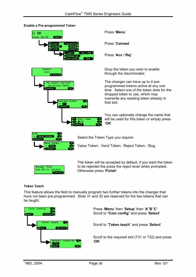
Enable a Pre-programmed Token
Press ‘Menu’
Press ‘Coinset’
Press ‘Acc / Rej’
Drop the token you wish to enablethrough the discriminator.
The changer can have up to 4 pre-programmed tokens active at any onetime. Select one of the token slots for thedropped token to use, which mayoverwrite any existing token already inthat slot.
You can optionally change the name thatwill be used for this token or simply press‘OK’
Select the Token Type you require:
Value Token; Vend Token; Reject Token; Slug
The token will be accepted by default, if you want the tokento be rejected the press the reject lever when prompted.Otherwise press ‘Finish’
Token Teach
This feature allows the field to manually program two further tokens into the changer thathave not been pre-programmed. Slots 31 and 32 are reserved for the two tokens that canbe taught.
Press ‘Menu’ then ‘Setup’ then ‘A’’B’’C’Scroll to “Coin config” and press ‘Select’
Scroll to “Token teach” and press ‘Select’
Scroll to the required slot (T31 or T32) and press‘OK’
CashFlow 7000 Series Engineers Guide
MEI, 2004 Page 37 Rev: G1
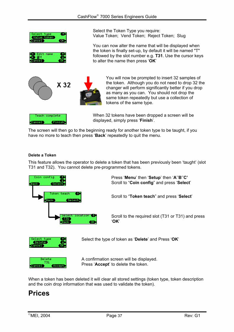
Select the Token Type you require:Value Token; Vend Token; Reject Token; Slug
You can now alter the name that will be displayed whenthe token is finally set-up, by default it will be named "T"followed by the slot number e.g. T31. Use the cursor keysto alter the name then press ‘OK’
You will now be prompted to insert 32 samples ofthe token. Although you do not need to drop 32 thechanger will perform significantly better if you dropas many as you can. You should not drop thesame token repeatedly but use a collection oftokens of the same type.
When 32 tokens have been dropped a screen will bedisplayed, simply press ‘Finish’.
The screen will then go to the beginning ready for another token type to be taught, if youhave no more to teach then press ‘Back’ repeatedly to quit the menu.
Delete a Token
This feature allows the operator to delete a token that has been previously been ‘taught’ (slotT31 and T32). You cannot delete pre-programmed tokens.
Press ‘Menu’ then ‘Setup’ then ‘A’’B’’C’Scroll to “Coin config” and press ‘Select’
Scroll to “Token teach” and press ‘Select’
Scroll to the required slot (T31 or T31) and press‘OK’
Select the type of token as ‘Delete’ and Press ‘OK’
A confirmation screen will be displayed.Press ‘Accept’ to delete the token.
When a token has been deleted it will clear all stored settings (token type, token descriptionand the coin drop information that was used to validate the token).
Prices
CashFlow 7000 Series Engineers Guide
MEI, 2004 Page 38
Price Holding:
The CF7000 has two methods of controlling the prices when being operated in Executivemode. These are ‘Prices Held in Machine’ (VMC) and ‘Prices Held in Changer’. The defaultfor this option is ‘Prices Held in Machine’
Prices Held in Machine:
The Prices are set up in the host machine to match the selection numbers, only the priceinformation is sent to the changer so it can audit the value of products sold but not whichproduct.i.e. The changer does not know if product 2 or product 6 was sold only that it was €0.20 inprice.
Prices Held in Changer:
The advantage of this setting is that the changer information, giving data by selection rather than g
The ‘prices’ in the host machine need to be set upcorresponds to the selection number.e.g. Selection 1 has a value of 1, selection 7 hasThe prices in the changer now need to be set up e.g. Price 1 set to €0.10, Price 7 set to €0.45
The CF7000 can support up to 100 selections wit
• •
• • • •
• •
• • • •
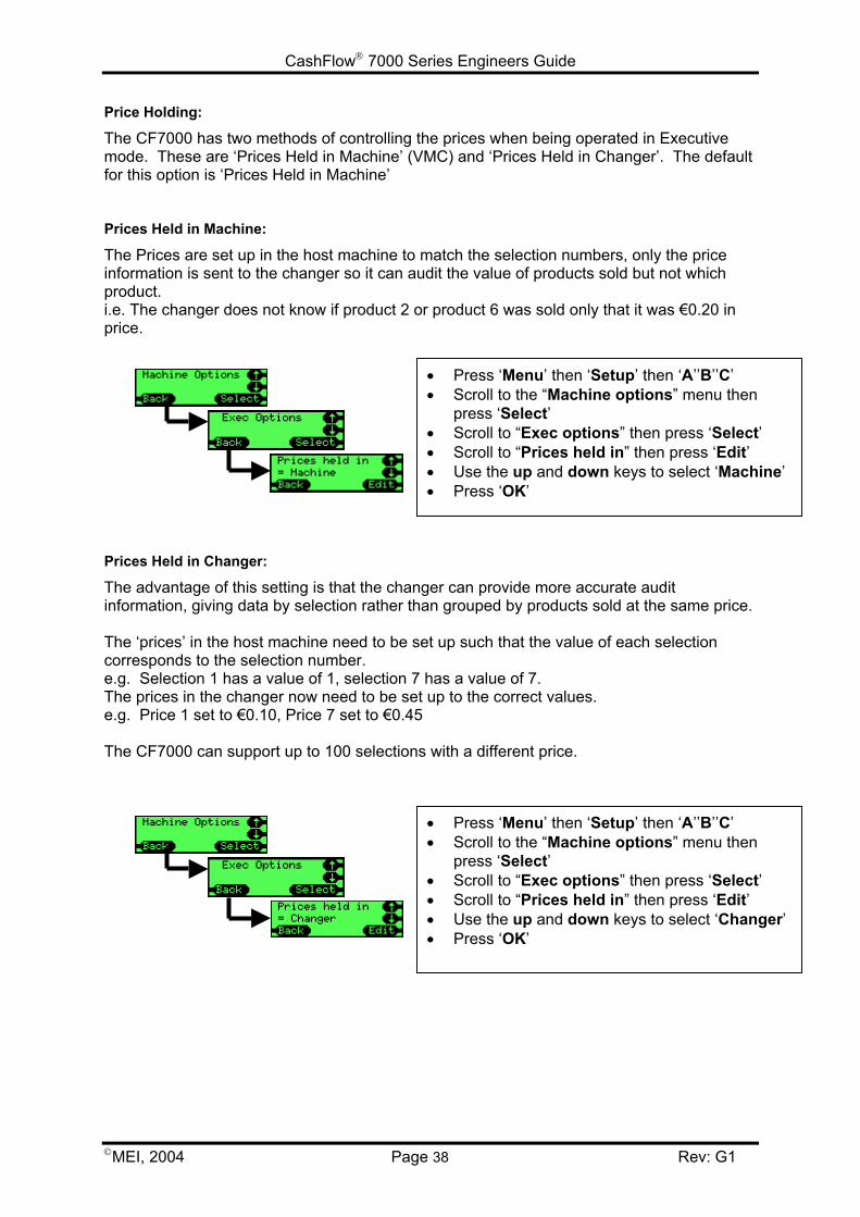
Press ‘Menu’ then ‘Setup’ then ‘A’’B’’C’Scroll to the “Machine options” menu thenpress ‘Select’Scroll to “Exec options” then press ‘Select’Scroll to “Prices held in” then press ‘Edit’Use the up and down keys to select ‘Machine’Press ‘OK’
Rev: G1
can provide more accurate auditrouped by products sold at the same price.
such that the value of each selection
a value of 7. to the correct values.
h a different price.
Press ‘Menu’ then ‘Setup’ then ‘A’’B’’C’Scroll to the “Machine options” menu thenpress ‘Select’Scroll to “Exec options” then press ‘Select’Scroll to “Prices held in” then press ‘Edit’Use the up and down keys to select ‘Changer’Press ‘OK’
CashFlow 7000 Series Engineers Guide
MEI, 2004 Page 39 Rev: G1
Setting Prices
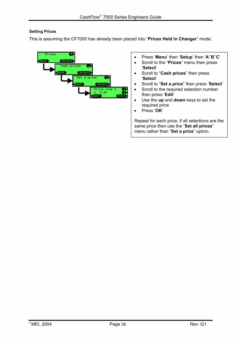
This is assuming the CF7000 has already been placed into “Prices Held in Changer” mode.
• Press ‘Menu’ then ‘Setup’ then ‘A’’B’’C’• Scroll to the “Prices” menu then press
‘Select’• Scroll to “Cash prices” then press
‘Select’• Scroll to “Set a price” then press ‘Select’• Scroll to the required selection number
then press ‘Edit’• Use the up and down keys to set the
required price• Press ‘OK’
Repeat for each price, if all selections are thesame price then use the “Set all prices”menu rather than “Set a price” option.
CashFlow 7000 Series Engineers Guide
MEI, 2004 Page 40 Rev: G1
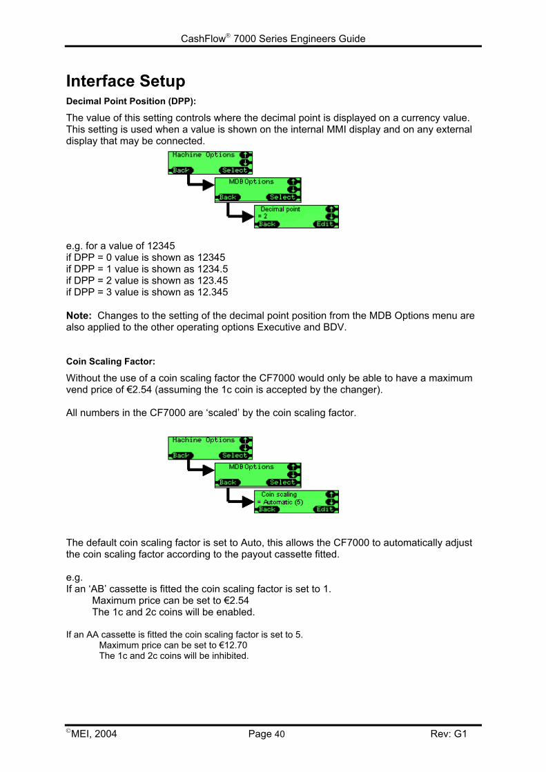
Interface SetupDecimal Point Position (DPP):
The value of this setting controls where the decimal point is displayed on a currency value.This setting is used when a value is shown on the internal MMI display and on any externaldisplay that may be connected.
e.g. for a value of 12345if DPP = 0 value is shown as 12345if DPP = 1 value is shown as 1234.5if DPP = 2 value is shown as 123.45if DPP = 3 value is shown as 12.345
Note: Changes to the setting of the decimal point position from the MDB Options menu arealso applied to the other operating options Executive and BDV.
Coin Scaling Factor:
Without the use of a coin scaling factor the CF7000 would only be able to have a maximumvend price of €2.54 (assuming the 1c coin is accepted by the changer).
All numbers in the CF7000 are ‘scaled’ by the coin scaling factor.
The default coin scaling factor is set to Auto, this allows the CF7000 to automatically adjustthe coin scaling factor according to the payout cassette fitted.
e.g.If an ‘AB’ cassette is fitted the coin scaling factor is set to 1.
Maximum price can be set to €2.54The 1c and 2c coins will be enabled.
If an AA cassette is fitted the coin scaling factor is set to 5.Maximum price can be set to €12.70The 1c and 2c coins will be inhibited.
CashFlow 7000 Series Engineers Guide
MEI, 2004 Page 41 Rev: G1
MDB
Level 2 or 3This feature has been introduced to cope with machines and changers that are older Level 2versions and hence increase backward compatibility of the changer. The default is Level 3.Only use Level 2 if the vending machine has a bug/issue with operating at Level 3.Level 2 – The changer will pretend to work at Level 2.Level 3 – The changer will work at Level 2 or 3 as requested by the vending machine.
Optimise Change (level 2)This is a new feature. It only affects MDB Level 2 dispense commands from the vendingmachine. Most machines (newer ones) use Level 3 so they are not affected.The default for this feature is OFF, only switch to ON if you are having problems, forexample short change on older machines.ON –The changer will work out the total change required (e.g. 3 x 10c), then compute abetter mix and pay that instead (e.g. 1 x 50c & 1 x 10c).OFF – The changer will pay exactly what is requested by the vending machine.
NOTE: If enabled this feature will affect the coin audit results stored by the host machine as the coins paid out by the changer are not those logged in the audit report.
Float Coins (Hide/report)Reporting float coins can help with audit on the few machines that can cope with this option.The default is Hide.Hide – Any coins accepted in float mode are not reported to the vending machine (andhence not credited).Report – Report any coins to the machine that are accepted in float mode.
Coin CountsSome machines coin count themselves and only use the changer counts if they differ bymore than 2 coins. The 0 to 4 transition in TRC mode can resynchronise these machines tothe same counts as the changer.TRC 0004 – as per the TRC report, zero coin counts below a level of 4.CF 1234 – as per CF560/690, reports the exact number of coins.
CountryThis code identifies the country by using the international telephone dialling code. It doesnot indicate what coin set is in the product and is typically only used for audit purposes totrack which country a changer is in. (E.g. 0001 = USA.)Some changers use the currency codes (e.g. 1978 = EURO currency code).
CashFlow 7000 Series Engineers Guide
MEI, 2004 Page 42 Rev: G1
EXEC
Price HoldingThis determines where the price is held.(see Prices on page 40).
Max CreditOn Single Vend it is typically set to just above the vend price (or to allow a bank note or bill).€0 to €655 – Available range allowed for Max Credit setting.
Price DisplayThis allows the user to see a price for a selection without having to insert any money. Theycan do this by pressing the selection key.Yes – Show price when selection pressed.No – Don’t show price.
Vend TypeThis determines what the changer will do with any excess credit once a Vend cycle hasbeen completed. There are two settings available, Single Vend and Multi Vend.Single Vend – Does one vend then pays change automatically.Multi Vend – Holds onto the excess credit after the initial vend and allows the customer toeither request another vend or vends (credit permitting) or press the reject lever. Once thereject lever is pressed the remaining credit is returned. This setting also returns the excess credit to the customer if there is no activity for a timeafter the initial vends.
Overpay and Overpay AmountAny excess credit that the customer has inserted into the machine will not be received aschange.e.g. customer inserts €2 and makes a €1 vend
there is only 75c of change in the coin tubes which is paid backhence customer has overpaid by 25c
This overpay value can be handled in two ways:Retained - the value is left within the system and is available for the next vend/customer.Cleared - any outstanding credit that cannot be repaid is reset to zero.
€0 to €655 – The amount of money the changer will potentially not pay back to thecustomer. €0 indicates that the customer will never be short changed. The exact changelight will be on in these conditions. Typical use will depend on the cassette. For example, ifthe lowest tube coin is 10c, it may allow an overpay of 5c (so 1c, 2c, 5c still accepted to cashbox but may not be able to pay back).
Any cleared overpay is typically recorded in an audit field otherwise balancing the moneytaken and product sold would be impossible.
There maybe legal ramifications for different countries as to whether overpay can be clearedor retained.
Escrow ReturnThis is used to stop people entering lots of small change, pressing reject to get a few largecoins back and emptying the changer of coins.
CashFlow 7000 Series Engineers Guide
MEI, 2004 Page 43 Rev: G1
Yes – The reject lever can be used to request money returned.No – The reject lever is ignored.
Vend Time LimitThis sets the amount of time the host machine has to complete the vend cycle (e.g. brewcoffee) and report the end of vend to the changer.0 – 255 (seconds) - Available range allowed for Vend Time Limit setting.
BDV
Award DiscountThis is the credit amount at which a discount is triggered.€0 to €655.35 – Available range allowed for Discount Amount setting.
Trigger DiscountThis is the amount of discount awarded when the award discount is reached.€0 to €655.35 - Available range allowed for Trigger Discount setting.
Max ChangeThe maximum value of change that can be paid back following a vend€0 to €655.35 – Available range allowed for Max Change setting.
Link Master IDThis is the communication ID of the master (controlling node) in the communication network0 to 255 – Available range allowed for Link Master ID.
Exact Change EquationThis defines the set of conditions (low tubes) which indicate an exact change condition.
The customer enters a value (defined by BDV 001 spec) which defines the conditions.
NOTE: This function was designed when changers only had three coin tubes. On four andfive tube changers it has been interpreted that BDV tubes ‘A’’B’’C’ refer to the lowest threecoin denomination tubes (excluding multiple coin tubes) e.g. 5c 5c 10c 10c 25c.‘A’ refers to 5c, ‘B’ refers to 10c, ‘C’ refers to 25c.The changer will effectively treat duplicate coin tubes as a single entity hence will only reporta tube as empty when both tubes are empty.
BDV eqn – Use the equation defined in the BDV equation. There are a lot of set up optionsas follows:• Equation – What tubes are checked (you will need to refer to a specification).
• Offset – The level the tubes must be at.
• Coin Inhibits (x14) – Whether a coin is inhibited when the exact change condition isreached.
MEI eqn – Use the simpler MEI equation (no set-up required). This will indicate the exactchange when any of the lowest 3 tubes have less than 5 coins. It will automatically inhibitcoins based on the overpay value.
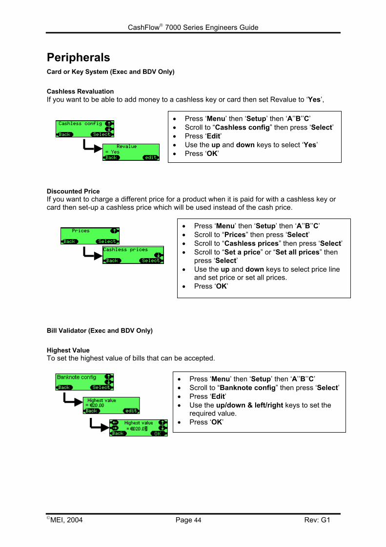
CashFlow 7000 Series Engineers Guide
MEI, 2004 Pa
PeripheralsCard or Key System (Exec and BDV Only)
Cashless RevaluationIf you want to be able to add money to a cashless key or card then set Revalue to ‘Yes’,
Discounted PriceIf you want to charge a different price for a card then set-up a cashless price which wil
Bill Validator (Exec and BDV Only)
Highest ValueTo set the highest value of bills that can be
• • • • •
••••
•
Press ‘Menu’ then ‘Setup’ then ‘A’’B’’C’Scroll to “Cashless config” then press ‘Select’Press ‘Edit’Use the up and down keys to select ‘Yes’Press ‘OK’
ge
product when it is paid for with a cashless key orl be used instead of the cash price.
ac
• • • •
•
•
Press ‘Menu’ then ‘Setup’ then ‘A’’B’’C’Scroll to “Prices” then press ‘Select’Scroll to “Cashless prices” then press ‘Select’Scroll to “Set a price” or “Set all prices” thenpress ‘Select’Use the up and down keys to select price lineand set price or set all prices.Press ‘OK’
cepted.
Press ‘Menu’ then ‘Setup’ then ‘A’’B’’C’Scroll to “Banknote config” then press ‘Select’Press ‘Edit’Use the up/down & left/right keys to set therequired value.Press ‘OK’
44 Rev: G1
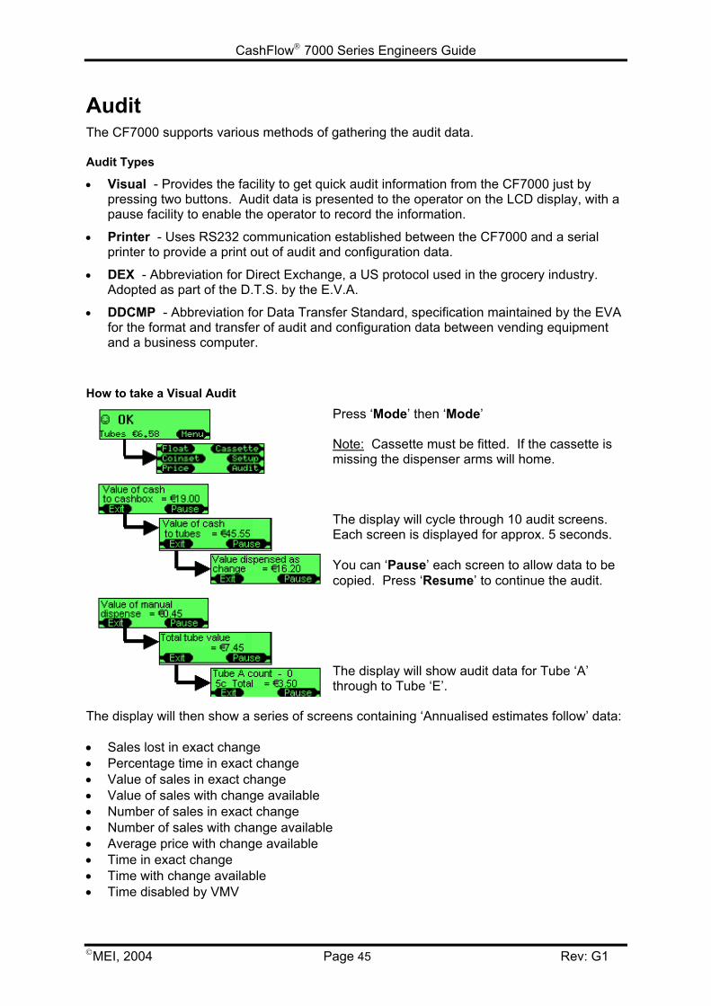
CashFlow 7000 Series Engineers Guide
MEI, 2004 Page 45 Rev: G1
AuditThe CF7000 supports various methods of gathering the audit data.
Audit Types
• Visual - Provides the facility to get quick audit information from the CF7000 just bypressing two buttons. Audit data is presented to the operator on the LCD display, with apause facility to enable the operator to record the information.
• Printer - Uses RS232 communication established between the CF7000 and a serialprinter to provide a print out of audit and configuration data.
• DEX - Abbreviation for Direct Exchange, a US protocol used in the grocery industry.Adopted as part of the D.T.S. by the E.V.A.
• DDCMP - Abbreviation for Data Transfer Standard, specification maintained by the EVAfor the format and transfer of audit and configuration data between vending equipmentand a business computer.
How to take a Visual Audit
Press ‘Mode’ then ‘Mode’
Note: Cassette must be fitted. If the cassette ismissing the dispenser arms will home.
The display will cycle through 10 audit screens.Each screen is displayed for approx. 5 seconds.
You can ‘Pause’ each screen to allow data to becopied. Press ‘Resume’ to continue the audit.
The display will show audit data for Tube ‘A’through to Tube ‘E’.
The display will then show a series of screens containing ‘Annualised estimates follow’ data:
• Sales lost in exact change• Percentage time in exact change• Value of sales in exact change• Value of sales with change available• Number of sales in exact change• Number of sales with change available• Average price with change available• Time in exact change• Time with change available• Time disabled by VMV
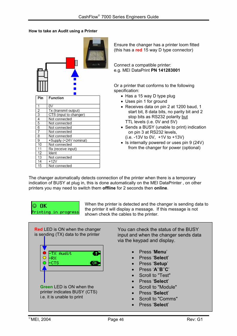
CashFlow 7000 Series Engineers Guide
MEI, 2004 Page 46 Rev: G1
Green LED is ON when theprinter indicates BUSY (CTS)i.e. it is unable to print
Red LED is ON when the changeris sending (TX) data to the printer
You can check the status of the BUSYinput and when the changer sends datavia the keypad and display.
• Press ‘Menu’• Press ‘Select’• Press ‘Setup’• Press ‘A’’B’’C’• Scroll to "Test"• Press ‘Select’• Scroll to "Module"• Press ‘Select’• Scroll to "Comms"• Press ‘Select’
How to take an Audit using a Printer
Ensure the changer has a printer loom fitted(this has a red 15 way D type connector)
Connect a compatible printer:e.g. MEI DataPrint PN 141283001
Or a printer that conforms to the followingspecification:
• Has a 15 way D type plug• Uses pin 1 for ground• Receives data on pin 2 at 1200 baud, 1
start bit, 8 data bits, no parity bit and 2stop bits as RS232 polarity but
TTL levels (i.e. 0V and 5V)• Sends a BUSY (unable to print) indication
on pin 3 at RS232 levels, (i.e. -13V to 0V, +1V to +13V)
• Is internally powered or uses pin 9 (24V)from the changer for power (optional)
The changer automatically detects connection of the printer when there is a temporaryindication of BUSY at plug in, this is done automatically on the MEI DataPrinter , on otherprinters you may need to switch them offline for 2 seconds then online.
When the printer is detected and the changer is sending data tothe printer it will display a message. If this message is notshown check the cables to the printer.
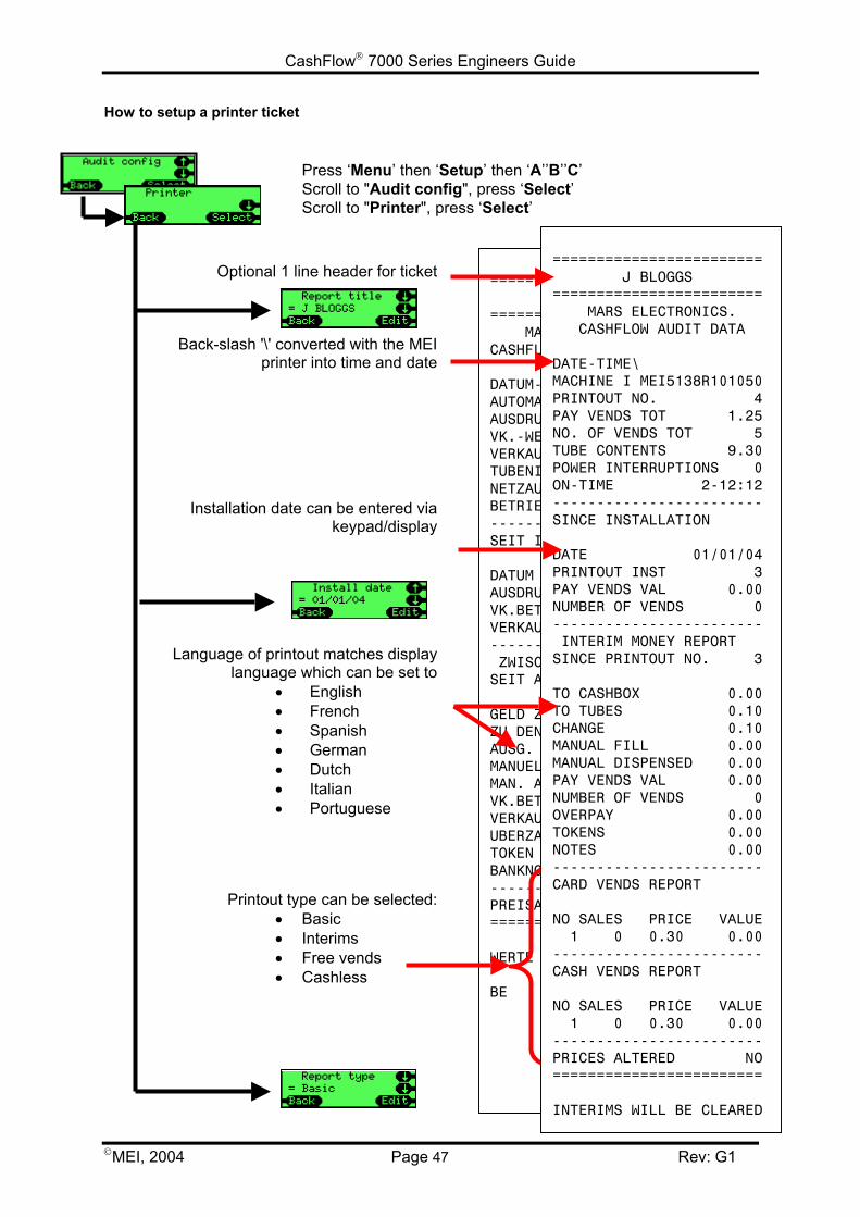
CashFlow 7000 Series Engineers Guide
MEI, 2004 Page 47
How to setup a printer ticket
Optional 1 line header for ticket
Back-slash '\' converted with the MEIprinter into time and date
Installation date can be entered viakeypad/display
Language of printout matches displaylanguage which can be set to
• English• French• Spanish• German• Dutch• Italian• Portuguese
Printout type can be selected:• Basic• Interims• Free vends• Cashless
======= ======= MARCASHFLO
DATUM-ZAUTOMATAUSDRUCVK.-WERVERKAUFTUBENINNETZAUSBETRIEB-------SEIT IN
DATUM AUSDRUCVK.BETRVERKAUF------- ZWISCHSEIT AU
GELD ZUZU DEN AUSG. RMANUELLMAN. AUVK.BETRVERKAUFUBERZAHTOKEN BANKNOT-------PREISAE=======
WERTE W
BE
Press ‘Menu’ then ‘Setup’ then ‘A’’B’’C’Scroll to "Audit config", press ‘Select’Scroll to "Printer", press ‘Select’
================= J BLOGGS=================S ELECTRONICS.W VERKAUFS-DATEN
EIT\EN MEI5138R101050K-NR 6T GES. 1.55SANZAHL 6HALT 9.10FALL 0SZEIT 2-12:18-----------------BETRIEBNAHME
01/01/04K-NR 5AG 0.30SANZAHL 1-----------------ENBETRAGSDRUCK-NR. 5
R KASSE 0.00TUBEN 0.00ESTGELD 0.00E FUELLUNG 0.00SZAHLUNG 0.00AG 0.00SANZAHL 0LUNG 0.00 0.00EN 0.00-----------------NDERUNG NEIN=================
ERDEN GELOESCHT
======================== J BLOGGS======================== MARS ELECTRONICS. CASHFLOW AUDIT DATA
DATE-TIME\MACHINE I MEI5138R101050PRINTOUT NO. 4PAY VENDS TOT 1.25NO. OF VENDS TOT 5TUBE CONTENTS 9.30POWER INTERRUPTIONS 0ON-TIME 2-12:12------------------------SINCE INSTALLATION
DATE 01/01/04PRINTOUT INST 3PAY VENDS VAL 0.00NUMBER OF VENDS 0------------------------ INTERIM MONEY REPORTSINCE PRINTOUT NO. 3
TO CASHBOX 0.00TO TUBES 0.10CHANGE 0.10MANUAL FILL 0.00MANUAL DISPENSED 0.00PAY VENDS VAL 0.00NUMBER OF VENDS 0OVERPAY 0.00TOKENS 0.00NOTES 0.00------------------------CARD VENDS REPORT
NO SALES PRICE VALUE 1 0 0.30 0.00------------------------CASH VENDS REPORT
NO SALES PRICE VALUE 1 0 0.30 0.00------------------------PRICES ALTERED NO========================
INTERIMS WILL BE CLEARED
Rev: G1
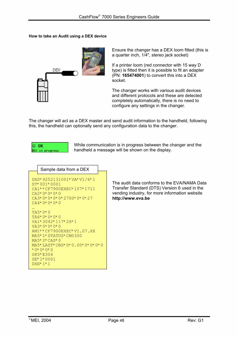
CashFlow 7000 Series Engineers Guide
MEI, 2004 Page 48 Rev: G1
How to take an Audit using a DEX device
Ensure the changer has a DEX loom fitted (this isa quarter inch, 1/4", stereo jack socket)
If a printer loom (red connector with 15 way Dtype) is fitted then it is possible to fit an adapter(PN: 165474001) to convert this into a DEXsocket.
The changer works with various audit devicesand different protocols and these are detectedcompletely automatically, there is no need toconfigure any settings in the changer.
The changer will act as a DEX master and send audit information to the handheld, followingthis, the handheld can optionally send any configuration data to the changer.
While communication is in progress between the changer and thehandheld a message will be shown on the display.
The audit data conforms to the EVA/NAMA DataTransfer Standard (DTS) Version 6 used in thevending industry, for more information websitehttp://www.eva.be
DXS*9252131001*VA*V1/6*1ST*001*0001CA1**CF7900EXEC*107*1711CA2*0*0*0*0CA3*0*0*0*0*2700*0*0*27CA4*0*0*0*0…TA5*0*0TA6*0*0*0*0VA1*3042*117*26*1VA3*0*0*0*0AM1**CF7900EXEC*V1.07.XXMA5*1*STATUS*CM0300MA5*2*CAS*0MA5*LAST*CBS*0*0.00*0*0*0*0*0*0*0*0G85*E304SE*1*0001DXE*1*1
Sample data from a DEX
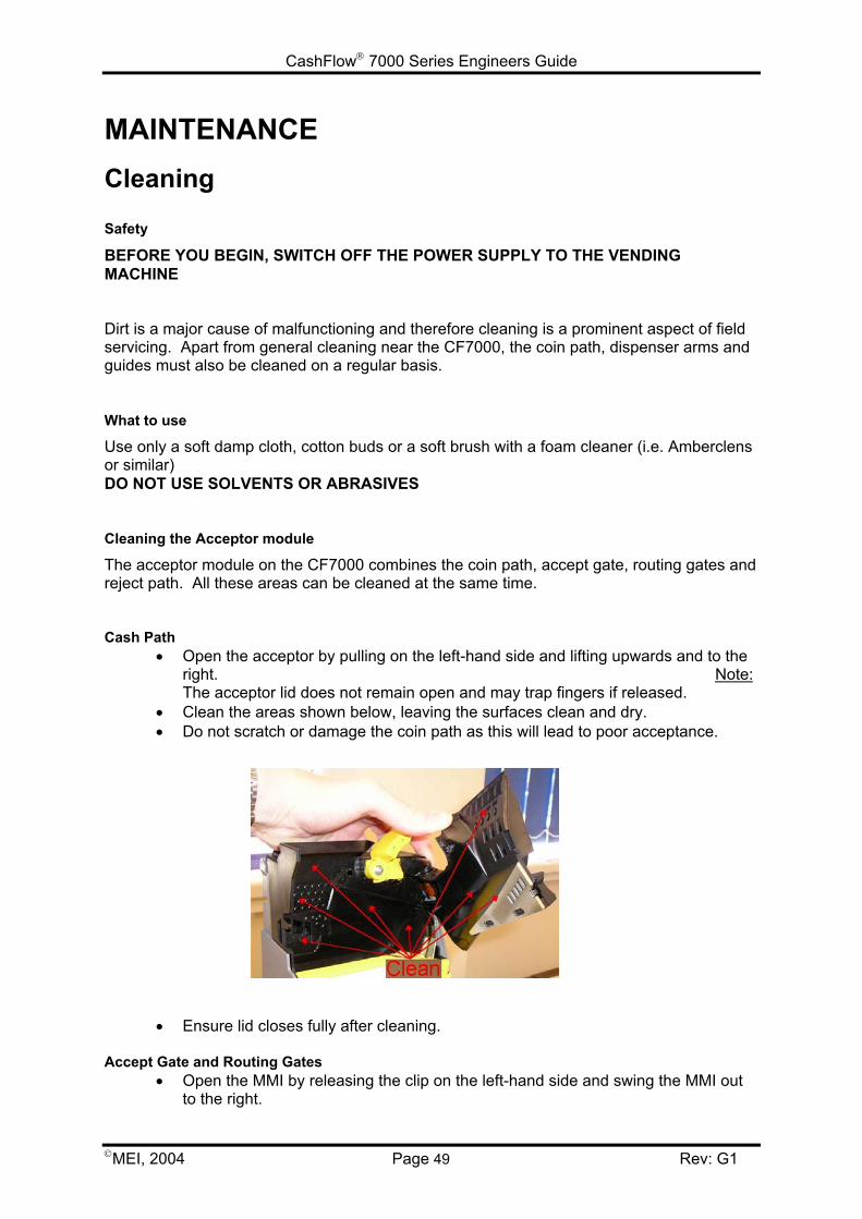
CashFlow 7000 Series Engineers Guide
MEI, 2004 Page 49 Rev: G1
MAINTENANCECleaning
Safety
BEFORE YOU BEGIN, SWITCH OFF THE POWER SUPPLY TO THE VENDINGMACHINE
Dirt is a major cause of malfunctioning and therefore cleaning is a prominent aspect of fieldservicing. Apart from general cleaning near the CF7000, the coin path, dispenser arms andguides must also be cleaned on a regular basis.
What to use
Use only a soft damp cloth, cotton buds or a soft brush with a foam cleaner (i.e. Amberclensor similar)DO NOT USE SOLVENTS OR ABRASIVES
Cleaning the Acceptor module
The acceptor module on the CF7000 combines the coin path, accept gate, routing gates andreject path. All these areas can be cleaned at the same time.
Cash Path• Open the acceptor by pulling on the left-hand side and lifting upwards and to the
right. Note:The acceptor lid does not remain open and may trap fingers if released.
• Clean the areas shown below, leaving the surfaces clean and dry.• Do not scratch or damage the coin path as this will lead to poor acceptance.
• Ensure lid closes fully after cleaning.
Accept Gate and Routing Gates• Open the MMI by releasing the clip on the left-hand side and swing the MMI out
to the right.
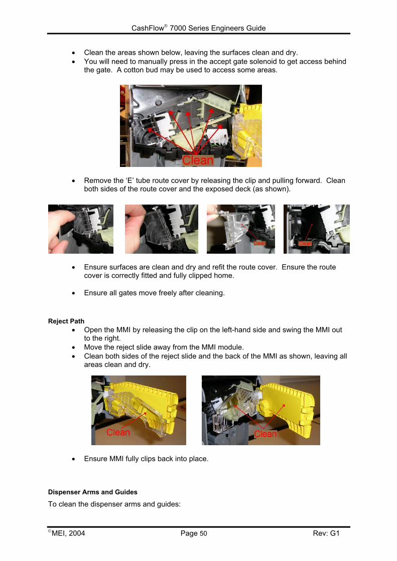
CashFlow 7000 Series Engineers Guide
MEI, 2004 Page 50 Rev: G1
• Clean the areas shown below, leaving the surfaces clean and dry.• You will need to manually press in the accept gate solenoid to get access behind
the gate. A cotton bud may be used to access some areas.
• Remove the ‘E’ tube route cover by releasing the clip and pulling forward. Cleanboth sides of the route cover and the exposed deck (as shown).
• Ensure surfaces are clean and dry and refit the route cover. Ensure the routecover is correctly fitted and fully clipped home.
• Ensure all gates move freely after cleaning.
Reject Path• Open the MMI by releasing the clip on the left-hand side and swing the MMI out
to the right.• Move the reject slide away from the MMI module.• Clean both sides of the reject slide and the back of the MMI as shown, leaving all
areas clean and dry.
• Ensure MMI fully clips back into place.
Dispenser Arms and Guides
To clean the dispenser arms and guides:
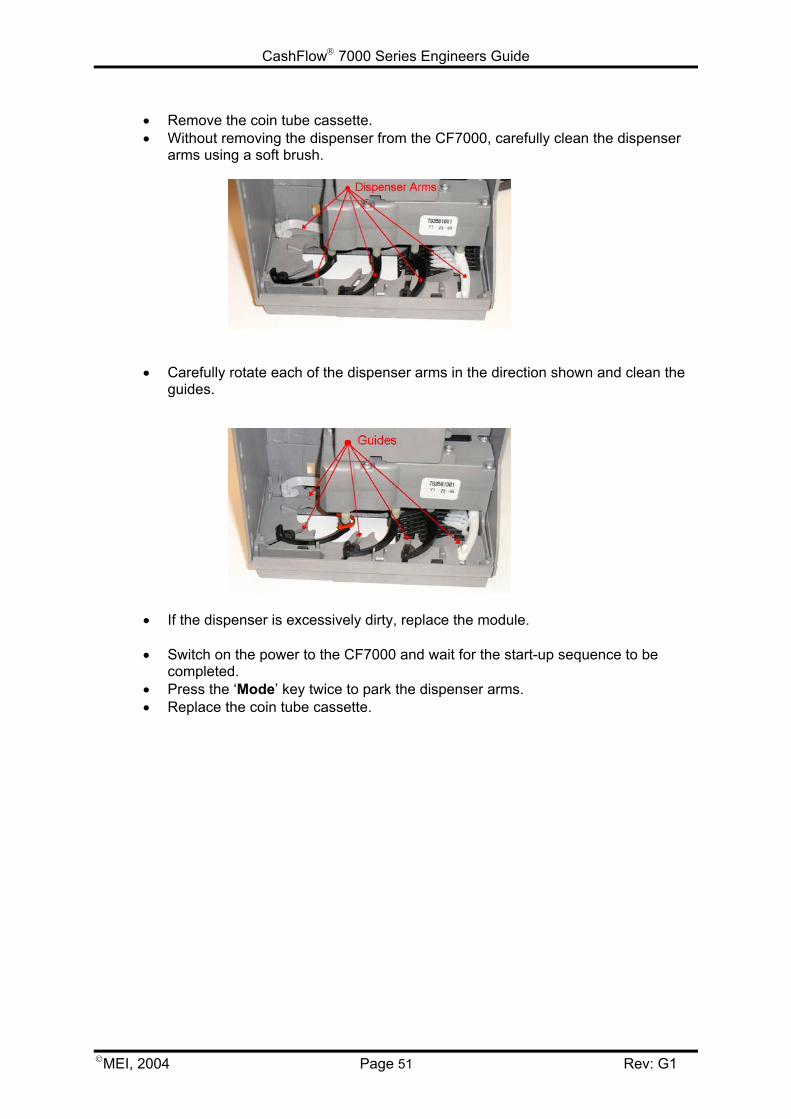
CashFlow 7000 Series Engineers Guide
MEI, 2004 Page 51 Rev: G1
• Remove the coin tube cassette.• Without removing the dispenser from the CF7000, carefully clean the dispenser
arms using a soft brush.
• Carefully rotate each of the dispenser arms in the direction shown and clean theguides.
• If the dispenser is excessively dirty, replace the module.
• Switch on the power to the CF7000 and wait for the start-up sequence to becompleted.
• Press the ‘Mode’ key twice to park the dispenser arms.• Replace the coin tube cassette.
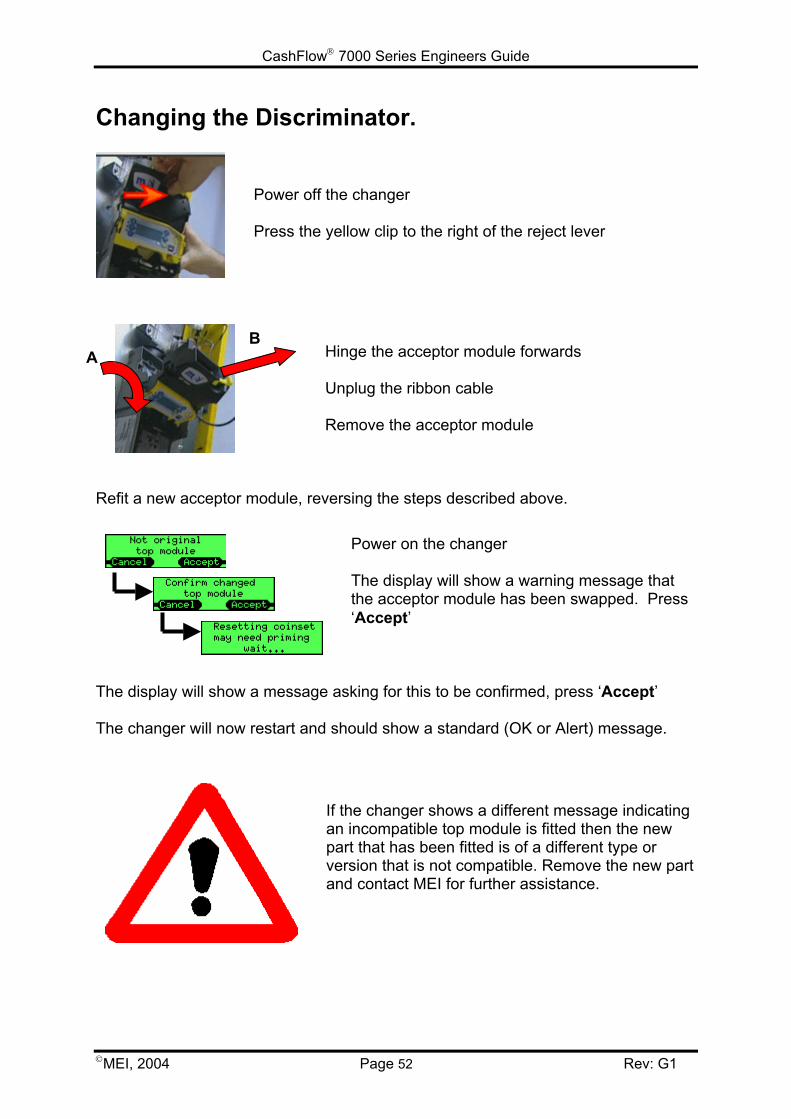
CashFlow 7000 Series Engineers Guide
MEI, 2004 Page 52 Rev: G1
Changing the Discriminator.
Power off the changer
Press the yellow clip to the right of the reject lever
Hinge the acceptor module forwards
Unplug the ribbon cable
Remove the acceptor module
Refit a new acceptor module, reversing the steps described above.
Power on the changer
The display will show a warning message thatthe acceptor module has been swapped. Press‘Accept’
The display will show a message asking for this to be confirmed, press ‘Accept’
The changer will now restart and should show a standard (OK or Alert) message.
If the changer shows a different message indicatingan incompatible top module is fitted then the newpart that has been fitted is of a different type orversion that is not compatible. Remove the new partand contact MEI for further assistance.
AB
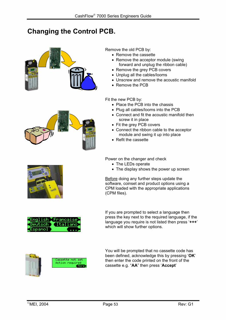
CashFlow 7000 Series Engineers Guide
MEI, 2004 Page 53 Rev: G1
Changing the Control PCB.
Remove the old PCB by:• Remove the cassette• Remove the acceptor module (swing
forward and unplug the ribbon cable)• Remove the grey PCB covers• Unplug all the cables/looms• Unscrew and remove the acoustic manifold• Remove the PCB
Fit the new PCB by:• Place the PCB into the chassis• Plug all cables/looms into the PCB• Connect and fit the acoustic manifold then
screw it in place• Fit the grey PCB covers• Connect the ribbon cable to the acceptor
module and swing it up into place• Refit the cassette
Power on the changer and check• The LEDs operate• The display shows the power up screen
Before doing any further steps update thesoftware, coinset and product options using aCPM loaded with the appropriate applications(CPM files).
If you are prompted to select a language thenpress the key next to the required language, if thelanguage you require is not listed then press ‘+++’which will show further options.
You will be prompted that no cassette code hasbeen defined, acknowledge this by pressing ‘OK’then enter the code printed on the front of thecassette e.g. “AA” then press ‘Accept’
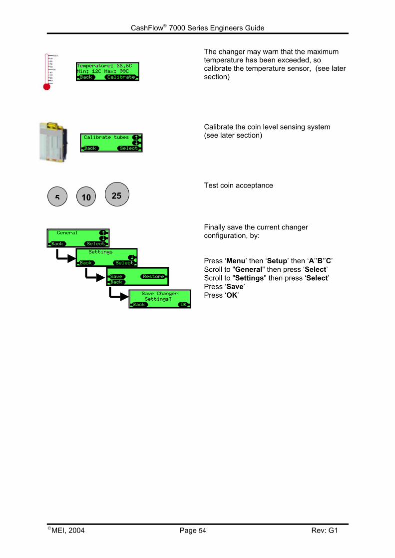
CashFlow 7000 Series Engineers Guide
MEI, 2004 Page 54 Rev: G1
The changer may warn that the maximumtemperature has been exceeded, socalibrate the temperature sensor, (see latersection)
Calibrate the coin level sensing system(see later section)
Test coin acceptance
Finally save the current changerconfiguration, by:
Press ‘Menu’ then ‘Setup’ then ‘A’’B’’C’Scroll to "General" then press ‘Select’Scroll to "Settings" then press ‘Select’Press ‘Save’Press ‘OK’
5 10 25
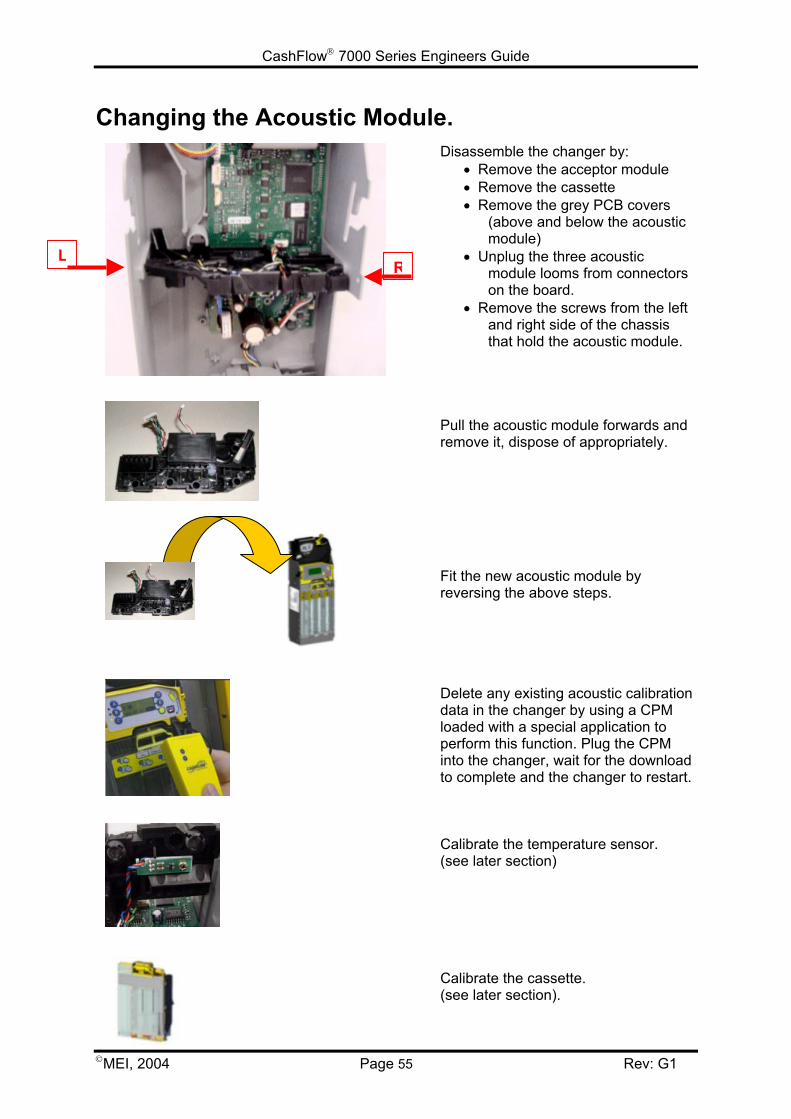
CashFlow 7000 Series Engineers Guide
MEI, 2004 Page 55 Rev: G1
Changing the Acoustic Module.Disassemble the changer by:
• Remove the acceptor module• Remove the cassette• Remove the grey PCB covers
(above and below the acousticmodule)
• Unplug the three acousticmodule looms from connectorson the board.
• Remove the screws from the leftand right side of the chassisthat hold the acoustic module.
Pull the acoustic module forwards andremove it, dispose of appropriately.
Fit the new acoustic module byreversing the above steps.
Delete any existing acoustic calibrationdata in the changer by using a CPMloaded with a special application toperform this function. Plug the CPMinto the changer, wait for the downloadto complete and the changer to restart.
Calibrate the temperature sensor. (see later section)
Calibrate the cassette. (see later section).
LR
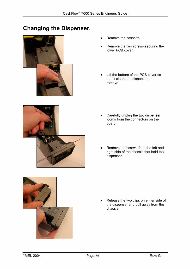
CashFlow 7000 Series Engineers Guide
MEI, 2004 Page 56 Rev: G1
Changing the Dispenser.• Remove the cassette.
• Remove the two screws securing thelower PCB cover.
• Lift the bottom of the PCB cover sothat it clears the dispenser andremove.
• Carefully unplug the two dispenserlooms from the connectors on theboard.
• Remove the screws from the left andright side of the chassis that hold thedispenser.
• Release the two clips on either side ofthe dispenser and pull away from thechassis.
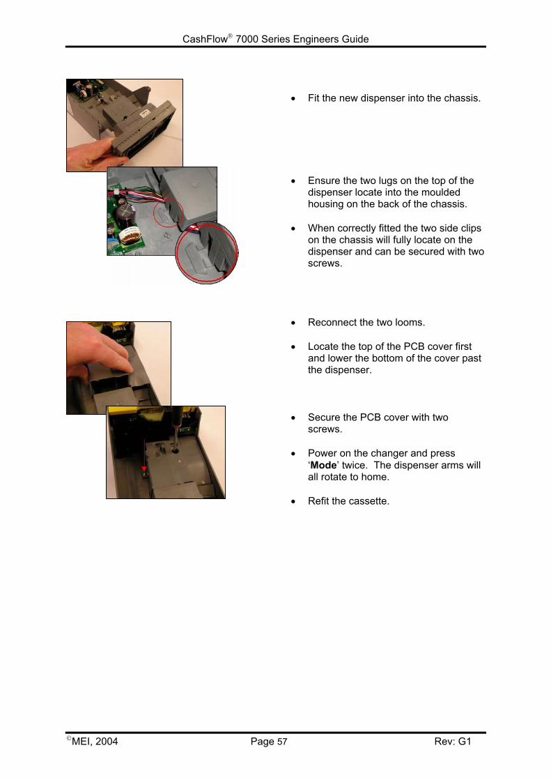
CashFlow 7000 Series Engineers Guide
MEI, 2004 Page 57 Rev: G1
• Fit the new dispenser into the chassis.
• Ensure the two lugs on the top of thedispenser locate into the mouldedhousing on the back of the chassis.
• When correctly fitted the two side clipson the chassis will fully locate on thedispenser and can be secured with twoscrews.
• Reconnect the two looms.
• Locate the top of the PCB cover firstand lower the bottom of the cover pastthe dispenser.
• Secure the PCB cover with twoscrews.
• Power on the changer and press‘Mode’ twice. The dispenser arms willall rotate to home.
• Refit the cassette.
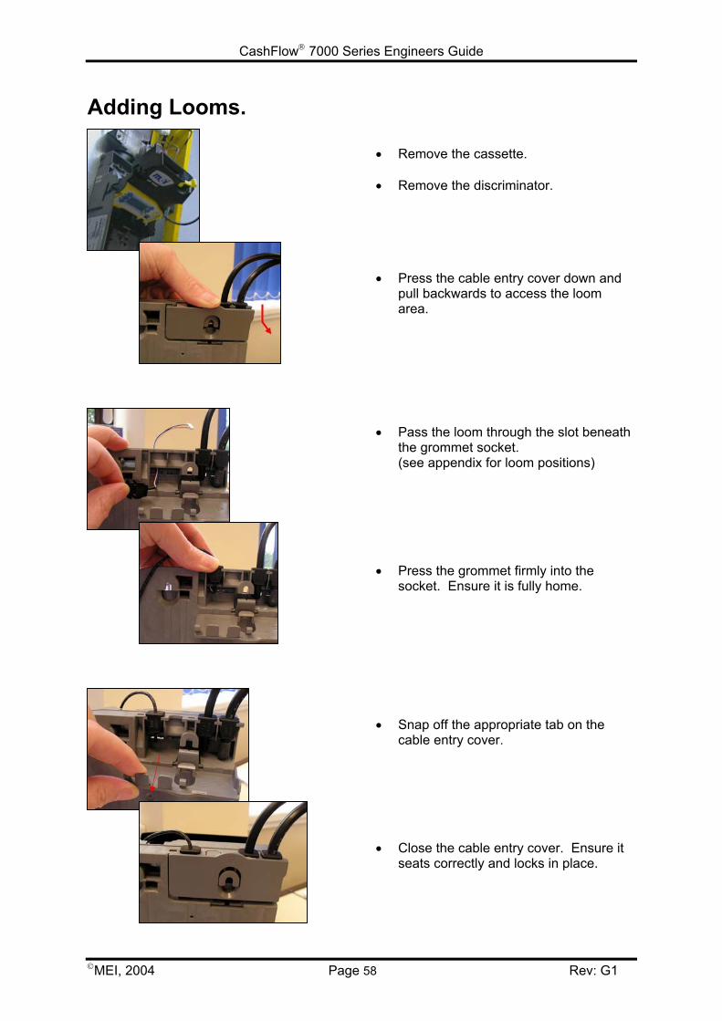
CashFlow 7000 Series Engineers Guide
MEI, 2004 Page 58 Rev: G1
Adding Looms.
• Remove the cassette.
• Remove the discriminator.
• Press the cable entry cover down andpull backwards to access the loomarea.
• Pass the loom through the slot beneaththe grommet socket. (see appendix for loom positions)
• Press the grommet firmly into thesocket. Ensure it is fully home.
• Snap off the appropriate tab on thecable entry cover.
• Close the cable entry cover. Ensure itseats correctly and locks in place.
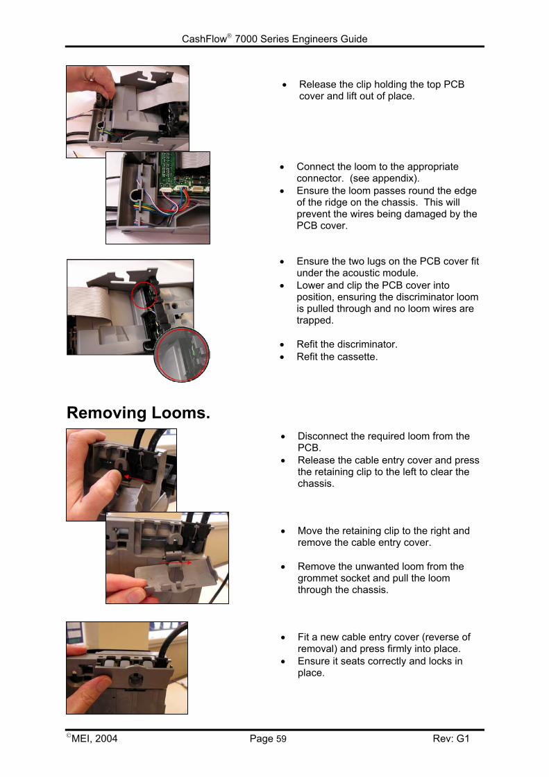
CashFlow 7000 Series Engineers Guide
MEI, 2004 Page 59 Rev: G1
• Release the clip holding the top PCBcover and lift out of place.
• Connect the loom to the appropriateconnector. (see appendix).
• Ensure the loom passes round the edgeof the ridge on the chassis. This willprevent the wires being damaged by thePCB cover.
• Ensure the two lugs on the PCB cover fitunder the acoustic module.
• Lower and clip the PCB cover intoposition, ensuring the discriminator loomis pulled through and no loom wires aretrapped.
• Refit the discriminator.• Refit the cassette.
Removing Looms.• Disconnect the required loom from the
PCB.• Release the cable entry cover and press
the retaining clip to the left to clear thechassis.
• Move the retaining clip to the right andremove the cable entry cover.
• Remove the unwanted loom from thegrommet socket and pull the loomthrough the chassis.
• Fit a new cable entry cover (reverse ofremoval) and press firmly into place.
• Ensure it seats correctly and locks inplace.
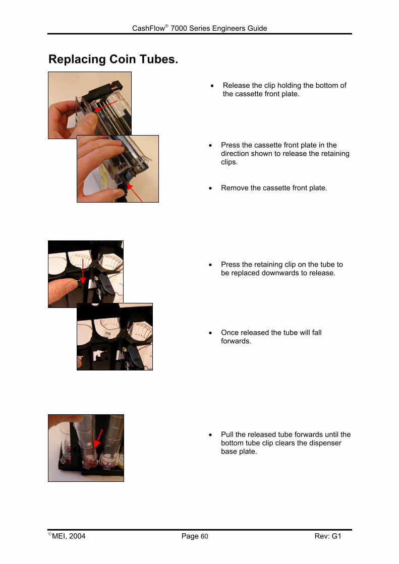
CashFlow 7000 Series Engineers Guide
MEI, 2004 Page 60 Rev: G1
Replacing Coin Tubes.
• Release the clip holding the bottom ofthe cassette front plate.
• Press the cassette front plate in thedirection shown to release the retainingclips.
• Remove the cassette front plate.
• Press the retaining clip on the tube tobe replaced downwards to release.
• Once released the tube will fallforwards.
• Pull the released tube forwards until thebottom tube clip clears the dispenserbase plate.
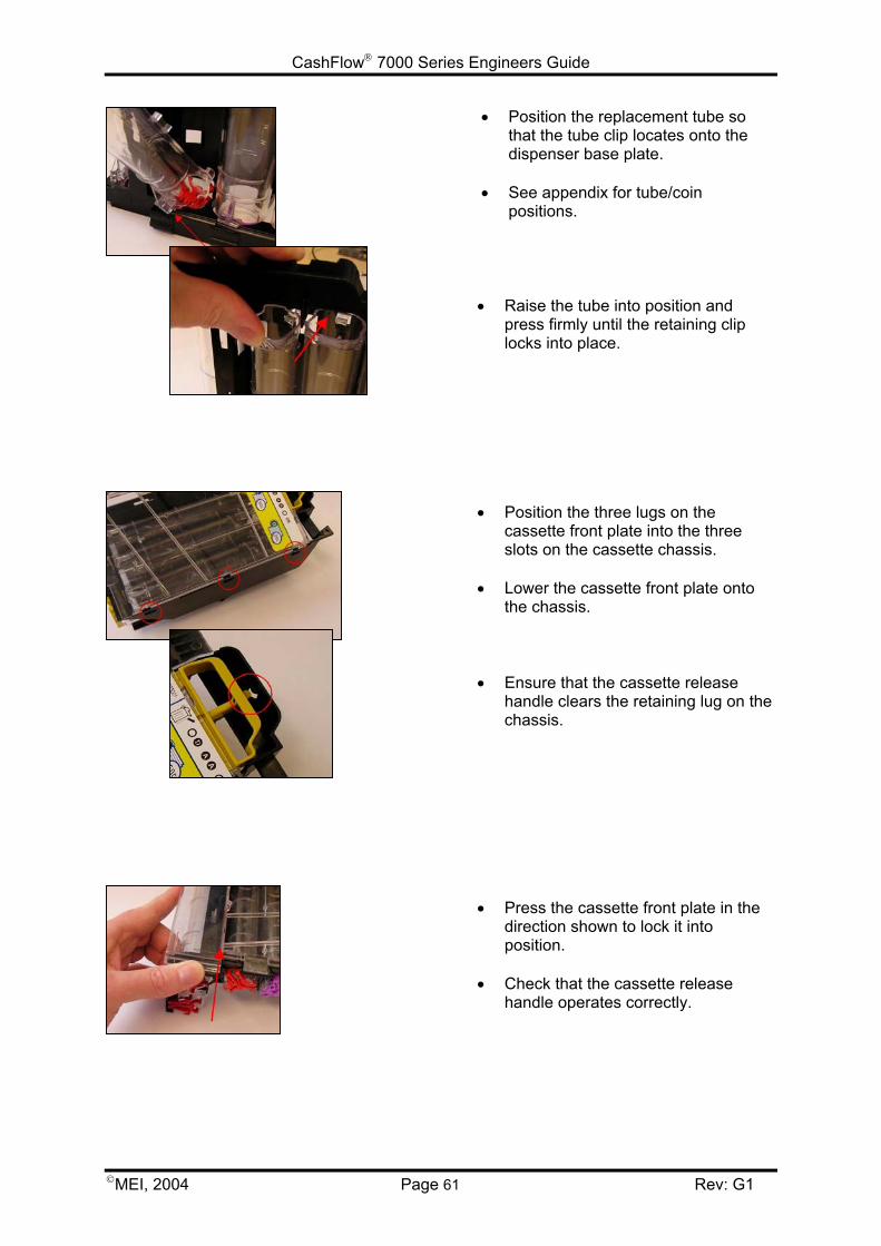
CashFlow 7000 Series Engineers Guide
MEI, 2004 Page 61 Rev: G1
• Position the replacement tube sothat the tube clip locates onto thedispenser base plate.
• See appendix for tube/coinpositions.
• Raise the tube into position andpress firmly until the retaining cliplocks into place.
• Position the three lugs on thecassette front plate into the threeslots on the cassette chassis.
• Lower the cassette front plate ontothe chassis.
• Ensure that the cassette releasehandle clears the retaining lug on thechassis.
• Press the cassette front plate in thedirection shown to lock it intoposition.
• Check that the cassette releasehandle operates correctly.
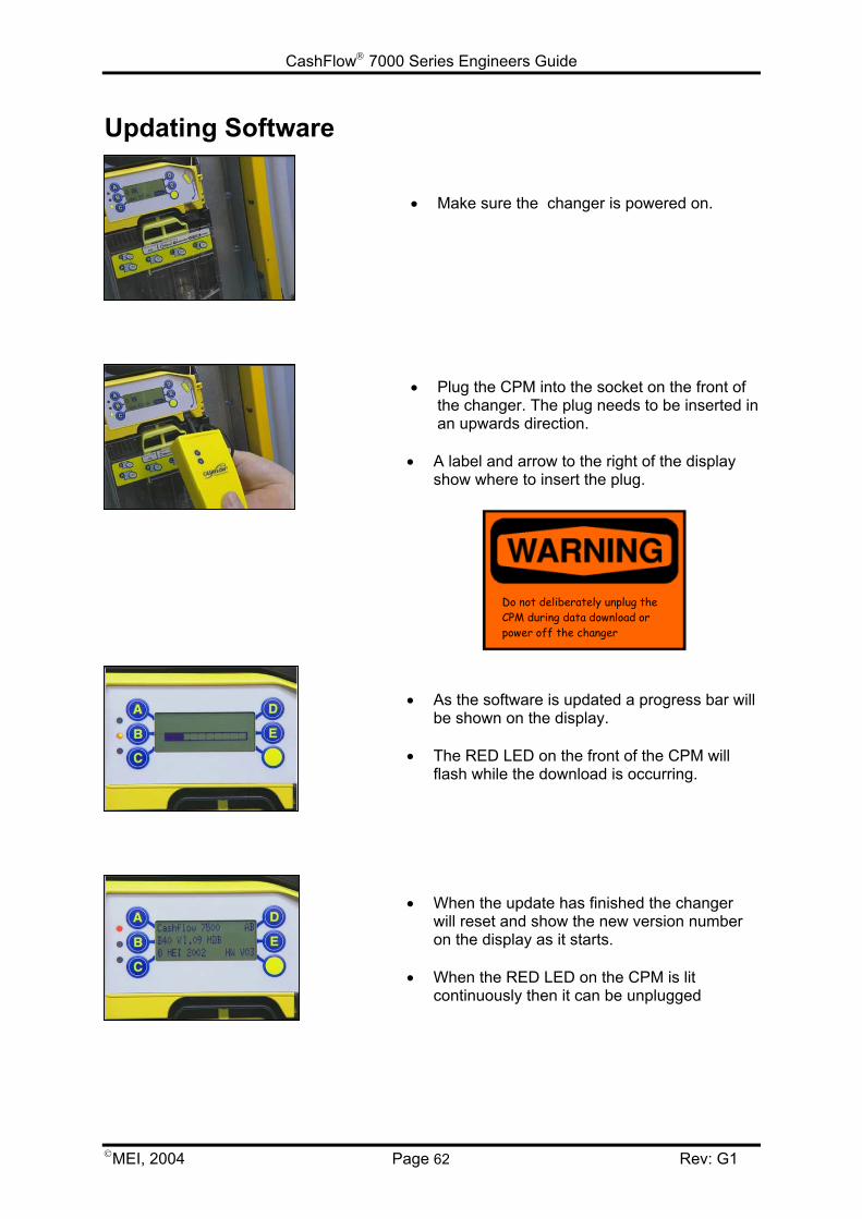
CashFlow 7000 Series Engineers Guide
MEI, 2004 Page 62 Rev: G1
Updating Software
• Make sure the changer is powered on.
• Plug the CPM into the socket on the front ofthe changer. The plug needs to be inserted inan upwards direction.
• A label and arrow to the right of the displayshow where to insert the plug.
• As the software is updated a progress bar willbe shown on the display.
• The RED LED on the front of the CPM willflash while the download is occurring.
• When the update has finished the changerwill reset and show the new version numberon the display as it starts.
• When the RED LED on the CPM is litcontinuously then it can be unplugged
Do not deliberately unplug theCPM during data download orpower off the changer
CashFlow 7000 Series Engineers Guide
MEI, 2004 Page 63 Rev: G1
PRODUCT SUPPORTIn addition to the MEI offices around the world an international network of Distributors andApproved Service Centres can offer you technical support and other services as well.These services include repairs, re-programming of your CF7000 products with new coinsets,replacing damaged modules, and the supply of a range of spare parts.
AUSTRIA
FRIEDRICH HOCHHAUSERLinzer Strasse123, A 4614MarchtrenkTel: +43 7243 58407Fax: +43 7243 5840714
BELGIUM / NETHERLANDS / LUXEMBURG
CASH SYSTEMS & SERVICE (CSS).Plasstraat 131860 MeiseTel: +32 (0)2 268 13 69Fax: +32 (0)2 268 65 02
FINLAND
MECSEL OY Soittajantie 100420 HelsinkiTel: +358 9700 18620Fax: +358 9700 18622
FRANCEG.T.I.Za Loire-Longue49160 Longue-JumellesTel: +33 (0) 241 537 000Fax: +33 (0) 241 537 001
L.M.Control39 Rue des Freres-LumiereBP2269680 Chassieu CedexTel: +33 (0) 472 477 400Fax: +33 (0) 472 477 411
GERMANY
AUTOMATEN-TECHNIK SCHREIERT GmbHAlter Teichweg 6322049 HamburgTel: +49 40 6918581Fax: +49 40 6929194
AUTOMATEN-TECHNIK SCHREIERT GmbHNiederlassung SüdBaindterstraße 46/288255 BaienfurtTel: +49 751 53028Fax: +49 751 5611919
AUTOMATEN-TECHNIK SCHREIERT GmbHHermann-Löns-Skr. 1958730 FröndenbergTel: +49 237 339 9739Fax: +49 237 339 9738
S+M SCHALTGERÄTESERVICE GmbHNiederlassung Rhein-MainMax-Planck-Str. 6a63486 Bruchköbel / HessenTel: +49 61 816 216 0Fax: +49 61 816 216 1
S+M SCHALTGERÄTESERVICE GmbHRichard-Lucas Straße 341812 Erkelenz /Industriegebiet OstTel: +49 24 319 654 0Fax: +49 24 317 613 7
S+M SCHALTGERÄTESERVICE GmbHNiederlassung HannoverBreslauer Straße 6430853 LangenhagenTel: +49 51 172 463 18Fax: +49 51 172 463 19
CashFlow 7000 Series Engineers Guide
MEI., 2003 Page 64 Rev: G1
GREAT BRITAIN
COIN SOLUTIONSUnit 3, Acorn Business CentreAcorn CourtButts StreetLeigh, Lancs. WN7 3DDTel: +44 (0)1942 733 322Fax: +44 (0)1942 733 399
MECHSHOP (SOUTH)80 Manor RoadWallingtonSurrey. SM6 0ABTel: +44 (0)208 669 9483Fax: +44 (0)208 669 6596
MECHSHOP (MIDLANDS)Unit 9, Arden Business CentreArden RoadAlcesterWarwickshire. B49 6HWTel: +44 (0)1789 793 963Fax: +44 (0)1789 400 882
MECHSHOP (NORTH)Linnyshaw Industrial EstateSharp StreetWalkdenManchester. M28 5WATel: +44 (0)161 790 0929Fax: +44 (0)161 790 0794
MICRO ELECTRONIC SERVICES (MES)7 Aircraft EsplanadeFarnboroughHampshire GU14 6TGTel: 01252 375302Fax: 01252 541615
GREECE
RADIO KATOUMAS15-19 Praxitelous Street105 62 Athens Tel: +30 10 3 250 412/6Fax: +30 10 3 237 296
IRELAND
COIN VALIDATIONSUnit 13, Navan Enterprise CentreTrim RoadCounty MeathTel: +353 46 74474Fax: +353 46 74474
ISRAEL
MARAP AUTOMATIC INSTRUMENTS LTD7 Imbar StreetKiryat AriePO Box 4016Petah Tikva 49130Tel: +972 3 9234470Fax: +972 3 9234465
ITALY
ESPERIA DISTRIBUZIONE s.r.l.Via della Misericordia 4520057 Vedano al Lambro (MI)Tel: +39 039 2495678Fax: +39 039 24956789
s.a.s. ERREMA di Temporiti & CVia dell'Industria 5-5/A20094 Corsico MITel: +39 02 45 869762Fax: +39 02 45 869784
VENDING ASSISTANCE TEAM (V.A.T. Srl)Via Benadir, 1420132 MILANTel: +39 02 28040704 / +39 02 26142244Fax: +39 02 28001971
VENDING MACHINES VERONA (V.M.V. Srl)Via Ritonda 78/L37047 S. Bonifacio (VR)Tel: +39 045 6 103288Fax: +39 045 6 103289
CashFlow 7000 Series Engineers Guide
MEI., 2003 Page 65 Rev: G1
PORTUGAL
ENA PORTUGALSistemas de Telecomunicacoes, S.A.Taguspark - EdicioTecnologia III66, 2780 OerasTel: +351 1 21 422 01 30Fax: +35 1 21 421 52 50
SPAIN
SISTEMAS ELECRONICOS de PAGO (SEP)c/Progres, 45 Pol. Ind. La Ferreria08110 Montcada i ReixacBarcelonaTel: +34 935 647 800Fax: +34 935 751 639
SISTIAGA LASA S.L.c/Olagarai, 2 Pol. Ugaldetxo20180 OiartzunGuipuzcoaTel: +34 943 493 176
Fax: +34 943 490 182TRATECNICA S.A.c/ Gonzalez Davila, 20-2 Aplanta Poligono Industrial de Vallecas 28031 Madrid Tel: +34 913 802 200 Fax: +34 913 802 652
TRATECNICA S.A.Poligono Zona Franca, 6808038 BarcelonaTel: +34 932 233 477Fax: +34 932 223 2743
Helping you deliverYOUR REPRESENTATIVE