
MEGARUBBER - Spruit Transmissies BV · 3 MEGARUBBER Introduction to open-end belts 4...
42
MEGARUBBER Rubber open-end timing belts
Transcript of MEGARUBBER - Spruit Transmissies BV · 3 MEGARUBBER Introduction to open-end belts 4...

ME
GA
RU
BB
ER
Ru
bb
er o
pe
n-e
nd
tim
ing
be
lts
MEGADYNE IS LOCATED IN
MATHI (ITALY) *TURIN (ITALY)VENICE (ITALY)MILAN (ITALY) *MINSK (BELARUS)PRAGUE (CZECH REPUBLIC)PARIS (FRANCE) * ST. JEAN DE MAURIENNE (FRANCE) *LION (FRANCE)BORCHEN (GERMANY)ULM (GERMANY) *BUDAPEST (HUNGARY)BYDGOSZCZ (POLAND)BARCELONA (SPAIN) *DUDLEY (UK)STOCKHOLM (SWEDEN)FOSHAN (CHINA)SHANGHAI (CHINA)QINGDAO (CHINA) *DUBAI (UAE)PINEVILLE-NC (USA) *SAO PAULO (BRASIL)NINGBO (CHINA)*
JASON IS LOCATED IN
NEW JERSEYILLINOISCALIFORNIAFLORIDATEXASOREGONQUEBECONTARIOALBERTAMEXICOBRASILSOUTH CAROLINA *
* MANUFACTURING FACILITIES
MEGADYNE HEADQUARTERVia Trieste 16 - 10075 Mathi (TO) - [email protected] - www.megadyne.it
ww
w.im
mag
ine3
000.
it

MEGARUBBERrubber open-end t iming belts

ISO 9001:2000 - ISO 14001:2004
MEGADYNE RUBBER S.A.

3
MEGARUBBER
3
Introductiontoopen-endbelts 4 Classifications 6 Calculationparameters 8 Trasmissioncalculationprocedure 10 Trasmissioncalculationexample 12 BeltinstallationandFeasibilitytable 14 Beltfailures 15
Beltdata MXL 16 XL 18 L 20 H 22
RPP3 24 RPP5 26 RPP8 28
SLV5 30 SLV8 32
STD8 34
Specialexecutionfeasibility 36 Fixingplates 37 UsefulformulasandConversiontable 38
TABLEOFCONTENTS

4
INTRODUCTIONTOOPENENDBELTS
MEGADYNE “OPEN END BELTS” are rubber based timing belts manufactured with high quality materials and state of the art production process. As a result of this MEGADYNE offers belts which have been designed to respond the high demands of today’s industrial market.
MEGADYNE “OPEN END BELTS” are specially suitable for reversing drives and applications where rotational movements need to be transformed into linear motions and high positioning accuracy is required.

5
MEGARUBBERMEGARUBBER
5
MEGADYNE “OPEN END BELTS” are a great solutionwhen substituting expensive conventional linearsystems . Noise level improvement will be obtained aswell as economical benefits due to the reduction of theinitial investment and the maintenance costs.
Taking into account the advantages and the availableproduct range, these belts can be considered as asolution for a very wide field of applications inindustrial equipments.
STANDARD RANGE
MXLStd. width (inches)
0.250.310.37
XLStd. w idth (inches)
0.250.310.37
LStd. width (inches)
0.500.751.00
HStd. width (inches)
0.500.751.001.502.003.00
P 12.7
H 4.4
H1 2.29
P 9.525
H 3.6
H1 1.91
P 5.08
H 2.4
H1 1.27
P 2.032
H 1.14
H1 0.51
SLV5Std. w idth (inches)
152530
SLV8Std. width (inches)
101520305085
STD8 MStd. width (inches)
1020305085
P 8
H 5.3
H1 3.05
P 8
H 5.4
H1 3.2
P 5
H 3.8
H1 2
RPP3Std. w idth (inches)
91215
RPP5Std. width (inches)
91215202530
RPP8Std. width (inches)
10152025305085
P 8
H 5.4
H1 3.2
P 5
H 3.8
H1 2
P 3
H 2.4
H1 1.15
ISORAN® MXL - XL - L - H
ISORAN® RPP
ISORAN® RPP SILVER
ISORAN® STD
P
H1
H
P
H1
H
P
H1
H
P
H1
H
MEGARUBBER-3-2009.qxd:MEGALINEAR.qxd 24-03-2009 10:32 Pagina 5
(mm)
(mm)
(mm)
(mm)
(mm)
(mm)
MEGADYNE “OPEN END BELTS” are a great solution when substituting expensive conventional linear systems. Noise level improvement will be obtained as well as economical benefits due to the reduction of the initial investment and the maintenance costs.Taking into account the advantages and the available product range, these belts can be considered as a solution for a very wide field of applications in industrial equipments.
STANDARD RANGE

6
CLASSIFICATIONS
MEGADYNE “OPEN END BELTS” are specially designed for reverse drives with long centre distance and for driveswhere rotation has to be translated into translatory movements.
The combination of different tooth profiles, belt widths and performance classes enables this type of belt to cover a wide range of application. Just few examples of typical applications can be:
• Automatic door opening systems for garages• Automatic sliding door systems• X-Y tables on tooling machines• Level control on elevator systems• Fitness machines• Printers• Linear positioning systems
The advantages of MEGADYNE “OPEN END BELTS” are:
• High positioning accuracy on reverse drives• Covers wide range of applications• Low noise level due to vibration absorbing characteristic of rubber• Low operation costs due to free maintenance and long lasting service life• Compact and light drives are feasible due to high specific belt performance
CLASSIFICATIONS
BELT BACK. The back side cushion protects the tensile member and permits due to its elasticity the use of
backside idlers.
TENSION MEMBERS. Fiberglass tensile member of the latest technology grants the longitudinal rigidity and
resistance of the belt.
BELT BODY. The belt body is made of special polychloroprene-based rubber compound. These compounds
guarantee highest tooth share resistance.
FABRIC. Hard wearing nylon fabric is bonded on tooth surface to improve torque carrying capacity. In addition
a special graphite impregnation process gives self lubricating action and increases drive efficiency.
FABRIC
BELT BODY
BELT CONSTRUCTION
TENSION MEMBERS
BELT BACK

7
BELT RESISTANCE
STANDARDResistance to:Mineral Oils LOW
Water MEDIUM
Acids/ Alkalis NONE
Solvents NONE
Oils LOW
Greases MEDIUM
Fuels NONE
Environment Agents MEDIUM
Temperature:
Min. T (°C) -30
Max T (°C) 80
Max peak T (°C) 95
MEGARUBBER
• Constant dimensions• Noiseless• Free maintenance• High flexibility with fiberglass cords• Linear speeds up to 70 m/s
• Low pretension• Constant length• High abrasion resistance• Standard working temperature -30°C / +80°C• High resistance to water
BODYMEGADYNE “OPEN END BELTS” are manufactured with polychoroprene compound. Special compounds (different hardnesses, special properties) are available on request. Here under some rubber characteristics:
Using the information in the table below, it is possible to identify the correct belt for every application.The code is composed of letters and numbers as the following example:
FAMILY. This code composed by letters and numbers indicates the selection profile.
WIDTH. This number indicates the width of requested belt. The value is in mm for a belt with metric pitch,
and in inch for a belt with imperial pitch.
WIDTHFAMILY +
MECHANICAL AND CHEMICAL CHARACTERISTICS
IDENTIFICATION CODE
MXL
RPP5M
RPP8M
025
20
85

8
FS: Service FactorF1: Load FactorF2: Teeth in mesh FactorF3: Ratio FactorF4: Reverse Bending Factor
FS= F1 + F3 + F4
F2
LOAD FACTOR (F1)
TEETH IN MESH FACTOR (F2)
RATIO FACTOR (F3)
REVERSE BENDING FACTOR (F4)
Applies only to speed-up ratios.
With reverse by back idlers.
F4
0,2
Speed ratios F3
1 / 1,24 -
1,25 / 1,74 0,10
1,75 / 2,49 0,20
2,50 / 3,49 0,30
3,50 and above 0,40
Uniform load 1.0
Daily service in hours
3-8 hours 8-16 hours 16-24 hours
With low peak load
With high peak load
With very high peak load
1,2
1,5
1,8
1,4
1,7
2,0
1,6
1,9
2,2
T.I.M. F2
12
10
8
6
1,0
0,8
0,6
0,4
SERVICE FACTORS
CALCULATIONPARAMETERS

9
MEGARUBBER
BELT WIDTH SELECTION
DIAGRAM 1

10
TIMING BELT PERIPHERAL FORCE CALCULATION
ESTIMATE THE BELT WIDTH AND PROFILE
DEFINITION OF PULLEYS
HORIZONTAL CONVEYING DRIVES Fu = mc · a + mc · g · μ
Fu = peripheral force
VERTICAL CONVEYING DRIVES Fu = mc · (a + g) + FRM
OMEGA LINEAR DRIVES Fu = mc · a + mc · g · μ
With the result of Fu select according DIAGRAM 1 on “Belt width selection” the belt type profile and approximate belt width.
Choose closest standard pulley according to the data sheet of each belt type.
z = π · dp1
Pitchn =
6000 · V
Pitch · Z
TRANSMISSIONCALCULATIONPROCEDURE
dpdp
mc
DRIVE CALCULATION PROCEDURE FOR HORIZONTAL CONVEYING DRIVES
DRIVE SKETCH DRIVE DATA
Type of application Automatic door systemType of load Low fluctuation loadDesired pulley pitch diameter dp = 38.2 [mm]Centre distance l = 3 [m]Mass of carriage mc = 100 [kg]Coefficient of friction μ = 0.3Lineal velocity v = 1.5 [m/s]Acceleration a = 1.5 [m/s2]Deceleration ab = 1.5 [m/s2]Gravitational acceleration g = 9.8 [m/s2]Fp specific tooth resistance Fp spec [N/cm]

11
MEGARUBBER
TOOTH RESISTANCE
Fp spec (N/cm) : TRASMITTABLE FORCE FOR TOOTH UNIT WIDTH (see table on belt data pages).
The belt width should be calculated using the
following formula:
From the calculated width factor (Fwidth) choose next
higher width factor from belt data page, and define
the belt width.
Fwidth = Fu · Fs
Fp spec · Zm
Fwidth : Width factor
Fu: From above calculation
Fs: Service factors (see table page 7)
Fp spec : Trasmittable force for tooth unit width
(see table on belt data pages)
Zm: Number of teeth in mesh on drive sprocket
(if calculated Zm > = 12 for an open-end
application use Zm = 12)
DETERMINATION OF BELT WIDTH
In order to guarantee the correct function of the drive check the safety factor against break as following:
σBL = BL
Fu + Ts
BL : Breaking load (see table on belt data pages)Fu: From above calculationTs: Tension, from above calculation
σBL : Safety real value
σBL≥ : See tableType Low security Mid. security High security
RPP belts 10 12 14
SLV belts 8 10 12
SAFETY CHECK
CALCULATION OF BELT TENSION
Ts = 0,7 · Fu
Ts = 0,9 · Fu
Ts = 1,1 · Fu
HORIZONTAL CONVEYING DRIVES
VERTICAL CONVEYING DRIVES
OMEGA LINEAR DRIVES

12
DRIVE CALCULATION PROCEDURE FOR HORIZONTAL CONVEYING DRIVES
dpdp
mc
TRANSMISSIONCALCULATIONEXAMPLE
DRIVE SKETCH DRIVE DATA
Type of application Automatic door systemType of load Low fluctuation loadDesired pulley pitch diameter dp = 38.2 [mm]Centre distance l = 3 [m]Mass of carriage mc = 100 [kg]Coefficient of friction μ = 0.3Lineal velocity v = 1.5 [m/s]Acceleration a = 1.5 [m/s2]Deceleration ab = 1.5 [m/s2]Gravitational acceleration g = 9.8 [m/s2] Fs = 1,4 [N/cm]
COMMENT EXPLANATION RESULT
Define the number of teeth on thedriver pulley
If pitch diameter is known:
z = (π • dp1)
Pitch
z = 3,14 • 38,2
= 24 teeth 5
Standard z = 24dp1 = 38.2 [mm]
If the linear speed is known:
n = 60000 • V
Pitch • z
n = 60000 • 1,5
= 750 [rpm] 5 • 24
If known rpm we can choose thecorrect Fp spec, spec in belt data (see table on belt data pages).
COMMENT EXPLANATION RESULT
Calculate the peripheral force.
Fu = mc • a + mc • g • μ
mc = 100 [kg] a = 1,5 [m/s2] g = 9,8 [m/s2] μ = 0,3
Fu = 1000 · 1,5 + 100 · 9,8 · 0,3
Fu = 444 [N]
COMMENT EXPLANATION RESULT
Choose belt type and estimate belt width.
With the result of Fu, selectaccording DIAGRAM 1
“Belt width selection” the belt type profile and the approximate
belt width.
First approach RPP 5M 15Belt typeBelt pitchBelt width
TIMING BELT PERIPHERAL FORCE CALCULATION
ESTIMATE THE BELT WIDTH AND PROFILE
DEFINITION OF PULLEYS
13
MEGARUBBER
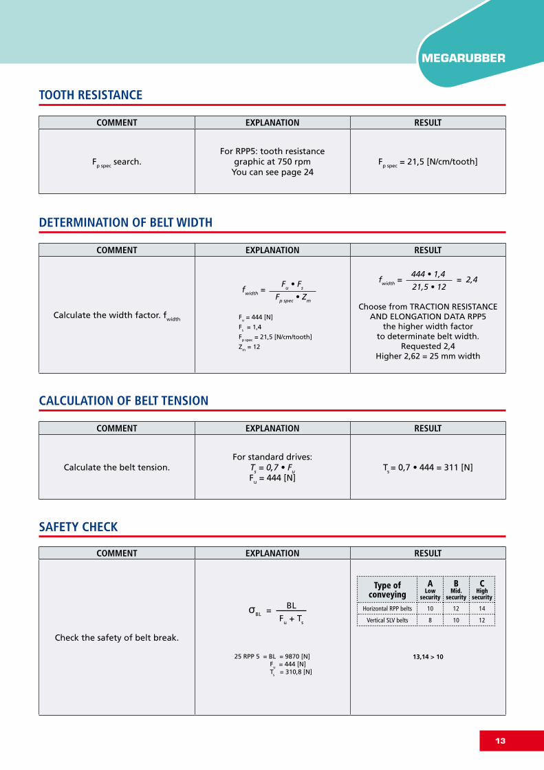
COMMENT EXPLANATION RESULT
Fp spec search.For RPP5: tooth resistance
graphic at 750 rpmYou can see page 24
Fp spec = 21,5 [N/cm/tooth]
TOOTH RESISTANCE
COMMENT EXPLANATION RESULT
Calculate the width factor. fwidth
fwidth = Fu • Fs
Fp spec • Zm
Fu = 444 [N]
Fs = 1,4
Fp spec = 21,5 [N/cm/tooth]
Zm = 12
fwidth = 444 • 1,4
= 2,4 21,5 • 12
Choose from TRACTION RESISTANCE AND ELONGATION DATA RPP5
the higher width factor to determinate belt width.
Requested 2,4Higher 2,62 = 25 mm width
DETERMINATION OF BELT WIDTH
COMMENT EXPLANATION RESULT
Calculate the belt tension.For standard drives:
Ts = 0,7 • Fu
Fu = 444 [N]Ts = 0,7 • 444 = 311 [N]
CALCULATION OF BELT TENSION
COMMENT EXPLANATION RESULT
Check the safety of belt break.
σBL = BL
Fu + Ts
25 RPP 5 = BL = 9870 [N] Fu = 444 [N] Ts = 310,8 [N]
13,14 > 10
Type of conveying
ALow
security
BMid.
security
CHigh
security
Horizontal RPP belts 10 12 14
Vertical SLV belts 8 10 12
SAFETY CHECK

14
Drawing 4
Where:
TS = Static tension (N)f = Frequency of vibration in Hertz (Hz)
m= Belt mass per unit length (kg/m) t= Free belt span length in meters (m)
f = Ts = 4 • m • t2 • f2 (16)or•1
2t
Ts
m
≥D
1+ D
2
2
D2
D1
TRAPEZOID PROFILE PARABOLIC PROFILESTANDARD
PROFILE
MXL XL L H RPP 3M RPP 5M RPP 8M SLV 5 SLV 8 STD 8MSTANDARD Standard S S S P S S P P P P
P Ex stock (Production process: Straight cut)
S Ex stock (Production process: Spiral cut)
PROCEDURE TO MEASUREThe procedure to measure the tension of the belt is to use a Belt Tension Gauging Equipement. This device consistsof a small sensing head which is held across the belt to be measured. The belt is then tapped to induce the belt tovibrate at its natural frequency. The vibrations are detected and the frequency of vibration is then displayed on themeasuring unit.The relation between belt static tension (TS) and frequency of vibration (f) may be calculated using the following
formula:
BELT AND PULLEY ALIGNMENTFor a correct system functioning and to increase belt life, it is necessary a correct pulley installation: pulleys has tobe parallel and aligned as shown in drawing 1 (correct configuration).If pulleys are not parallel as in drawing 2, belt could fall during functioning and this can cause damages to complete equipment.To grant a correct belt running, configuration according drawing 3 has to be avoided.
FEASIBILITY TABLEMEGADYNE manufactures a wide range of open-end belts. In the next table a general overview is shown of the present range of products and their main characteristics. For any special belt version which might not be included, please donot hesitate to contact our Application Engineering Team, or check page 36 “Special Execution Feasibility”.
In omega application to grant good mesh between pulley and teeth and to respect belt flexibility avoidingexcessive stress on cords, distance d (as drawing 4) hasto be:
BELTINSTALLATIONANDFEASIBILITYTABLEMEGARUBBER

15
MEGARUBBER
PROBLEMS CAUSES CORRECTION ACTION
Unexpected wear along thecomplete tooth width. Belt overload. Use a wider belt.
Use a belt of a higher performance class.
Unexpected wear on one side ofthe tooth only.
Incorrect pulley execution.Incorrect pulley alignment.
Control pulley dimensions and replace ifnecessary.Control and adjust pulley alignment.
Tooth bottom shows wear. Excessive belt installation tension.Incorrect pulley execution.
Calculate and adjust the belt tension.Control pulley dimensions and replace ifnecessary.
Tooth root shows signs of wear. Incorrect diameter of pulley. Control pulley dimensions and replace ifnecessary.
The flanks of the belt show clearsigns of wear.
Incorrect pulley execution. Control pulley dimensions and replace ifnecessary.
Misalignment or wrong setting of pulleys Control pulley dimensions and replace ifnecessary.
Oscillation of the axes and/or of the bearings Correct the positioning of the pulleys andreinforce the bearings
Flanks bent Straighten flanks
Damaged belt tensile member.Diameter of pulley is below specifiedminimum.
Increase the diameter of the pulleys or usebelts and pulleys of smaller pitch
Excessive moisture Eliminate the moisture
Torn tooth along the belt.
Too few teeth in mesh on the motor pulley.
Increase the number of teeth in mesh byusing a bigger pulley.Use a belt of a higher performance class.Increase belt width.
Belt overload. Use a belt of a higher performance class orincrease belt width.
Incorrect pulley execution. Control pulley dimensions and replace ifnecessary.
Rupture of tensile member.
Belt overload. Use a belt of a higher performance class.Increase belt width.
Diameter of pulley is below specifiedminimum. Increase the diameter of the pulleys
Tooth jump due to missing belt installationtension. Calculate and adjust the belt tension.
Breaks or cracks in the back sideof the belt.
Exposure to temperatures which are out ofthe admissible temperature range.
Protect the transmission from extremetemperature.
Diameter of pulley is below specifiedminimum. Increase the diameter of the pulleys
Excessive exposure to UV radiation.
Softening of the top surface ofthe belt. Operation with excessive amount of oil. Protect the belt from oil.
Apparent elongation of the belt. Reduction of centre distance due to bearingsnot being firmly fixed
Restore the initial centre distance andstrengthen the bearings
Belt overriding the pulley flanks.Faulty installation of the flanks. Reinstall the flanks properly.
Misalignment of pulleys. Align pulleys.
Excessive wear on the pulleyteeth.
Excessive overloading. Use a wider belt.
Excessive belt installation tension. Calculate and adjust the belt tension.
Pulley material insufficient hard. Harden the pulley surface.
Drive excessively noisy.
Pulleys out of line. Align pulleys.
Excessive belt installation tension. Calculate and adjust the belt tension.
Incorrect pulley execution. Control pulley dimensions and replace ifnecessary.
EX
CESSIV
E B
ELT
WEA
RB
ELT
DA
MA
GES
DR
IVE
FUN
CTI
ON
PR
OB
LEM
SBELTFAILURES

16
CALCULATION PARAMETERS
BELT ELONGATION
2.032
1.14
0.51
Elongation [%]
Load
[N]
0,1
BELT CHARACTERISTICS
TRACTION RESISTANCE AND ELONGATION DATA
025
031
037
1
1,24
1,55
660
7780
940
STANDARD WIDTHS (inch) 025
8,5Weight (gr/m)
031
10,5
037
16
MEGARUBBERMXLOPEN-END(SPIRALCUT)
Standard compound: Chloroprene 78±4 ShAStandard back cover: none, grinded on the backStandard tooth cover: nylon FabricStandard cords: glassStandard width tolerance: ± 0,4 mmStandard thickness: ± 0,25 mmStandard length tolerance: ± 0,8 mm/mStandard roll length: 50 mt ± 4 mt
Belt width (inch) Width Factor (W) Breaking Load [N]

17
MEGARUBBER
Glass cords 12 14 20 12 20
MXL
RPM (1/min)
F p s
pec
(N/c
m)
TOOTH RESISTANCE
FLEXION RESISTANCE
PULLEYS (for more details please see our pulleys catalogue)
N°Teeth Dp De
12 7,76 7,25
13 8,41 7,90
14 9,06 8,55
15 9,70 9,19
16 10,35 9,84
17 11,00 10,49
18 11,64 11,13
19 12,29 11,78
20 12,94 12,43
21 13,58 13,07
22 14,23 13,72
24 15,52 15,01
26 16,81 16,30
N°Teeth Dp De
28 18,11 17,60
30 19,40 18,89
32 20,70 20,19
34 21,99 21,48
36 23,29 22,78
40 25,87 25,36
42 27,17 26,66
44 28,46 27,95
48 31,05 30,54
60 38,81 38,30
65 42,04 41,53
72 46,57 46,06
Z min Z min Z mindler min dia (mm) dler min dia (mm)

18
5.08
2,4
1,27
Elongation [%]
Load
[N]
0,1
BELT CHARACTERISTICS
TRACTION RESISTANCE AND ELONGATION DATA
STANDARD WIDTHS (inch) 025
12,5Weight (gr/m)
031
17,5
037
21
025
031
037
1
1,24
1,55
940
1200
1410
Belt width (inch) Width Factor (W) Breaking Load [N]
MEGARUBBERXLOPEN-END(SPIRALCUT)
CALCULATION PARAMETERS
BELT ELONGATION
Standard compound: Chloroprene 78±4 ShAStandard back cover: none, grinded on the backStandard tooth cover: nylon FabricStandard cords: glassStandard width tolerance: - 0,8 / +0,4 mmStandard thickness: ± 0,25 mmStandard length tolerance: ± 0,8 mm/mStandard roll length: 50 mt ± 4 mt

19
MEGARUBBERXL
Glass cords 10 11 35 10 35
RPM (1/min)
F p s
pec
(N/c
m)
Z min Z min Z mindler min dia (mm) dler min dia (mm)
TOOTH RESISTANCE
FLEXION RESISTANCE
PULLEYS (for more details please see our pulleys catalogue)
N°Teeth Dp De
10 16,17 15,66
11 17,79 17,28
12 19,40 18,89
13 21,02 20,51
14 22,64 22,13
15 24,26 23,75
16 25,87 25,36
17 27,49 26,98
18 29,11 28,60
19 30,72 30,21
20 32,34 31,83
21 33,96 33,45
22 35,57 35,07
24 38,81 38,30
N°Teeth Dp De
26 42,04 41,53
27 43,67 43,16
28 45,28 44,77
29 46,89 46,38
30 48,51 48,00
32 51,74 51,23
34 54,98 54,47
35 56,60 56,09
36 58,21 57,70
38 61,45 60,94
39 63,06 62,55
40 64,68 64,17
42 67,91 67,40
44 71,15 70,64

20
9,525
3,6
1,91
Elongation [%]
Load
[N]
0,15
BELT CHARACTERISTICS
TRACTION RESISTANCE AND ELONGATION DATA
MEGARUBBERLOPEN-END(SPIRALCUT)
STANDARD WIDTHS (inch) 050
42Weight (gr/m)
075
62
100
102
CALCULATION PARAMETERS
BELT ELONGATION
Standard compound: Chloroprene 78±4 ShAStandard back cover: none, grinded on the backStandard tooth cover: nylon FabricStandard cords: glassStandard width tolerance: ± 0,6 mmStandard thickness: ± 0,25 mmStandard length tolerance: ± 0,8 mm/mStandard roll length: 50 mt ± 4 mt
050
075
100
1
1,25
2,15
2500
3500
4700
Belt width (inch) Width Factor (W) Breaking Load [N]
21
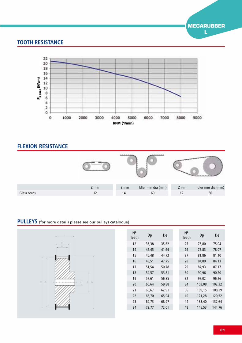
MEGARUBBERL
Glass cords 12 14 60 12 60
RPM (1/min)
F p s
pec
(N/c
m)
TOOTH RESISTANCE
FLEXION RESISTANCE
PULLEYS (for more details please see our pulleys catalogue)
Z min Z min Z mindler min dia (mm) dler min dia (mm)
N°Teeth Dp De
12 36,38 35,62
14 42,45 41,69
15 45,48 44,72
16 48,51 47,75
17 51,54 50,78
18 54,57 53,81
19 57,61 56,85
20 60,64 59,88
21 63,67 62,91
22 66,70 65,94
23 69,73 68,97
24 72,77 72,01
N°Teeth Dp De
25 75,80 75,04
26 78,83 78,07
27 81,86 81,10
28 84,89 84,13
29 87,93 87,17
30 90,96 90,20
32 97,02 96,26
34 103,08 102,32
36 109,15 108,39
40 121,28 120,52
44 133,40 132,64
48 145,53 144,76
22
12,7
4,4
2,29
Elongation [%]
Load
[N]
0,2
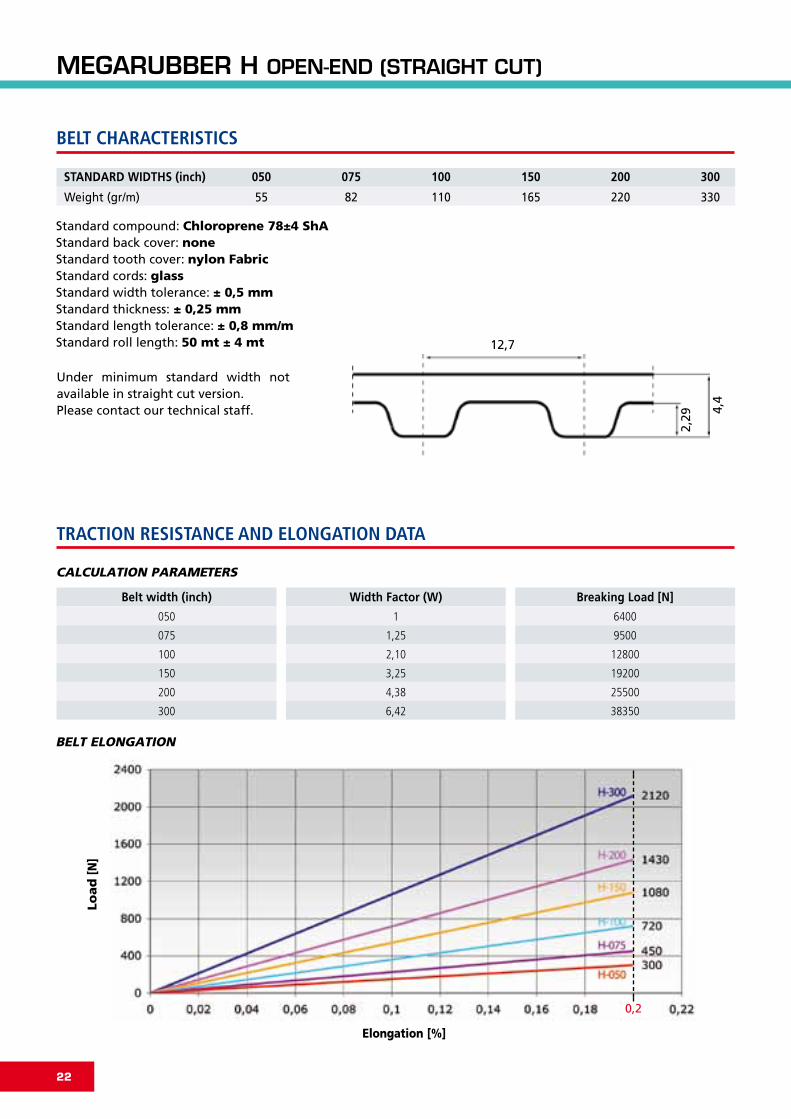
BELT CHARACTERISTICS
TRACTION RESISTANCE AND ELONGATION DATA
MEGARUBBERHOPEN-END(STRAIGHTCUT)
STANDARD WIDTHS (inch) 050
55Weight (gr/m)
150100075
16511082
300200
330220
Standard compound: Chloroprene 78±4 ShAStandard back cover: noneStandard tooth cover: nylon FabricStandard cords: glassStandard width tolerance: ± 0,5 mmStandard thickness: ± 0,25 mmStandard length tolerance: ± 0,8 mm/mStandard roll length: 50 mt ± 4 mt
CALCULATION PARAMETERS
BELT ELONGATION
050
075
100
150
200
300
1
1,25
2,10
3,25
4,38
6,42
6400
9500
12800
19200
25500
38350
Belt width (inch) Width Factor (W) Breaking Load [N]
Under minimum standard width not available in straight cut version.Please contact our technical staff.

23
MEGARUBBERH
Glass cords 14 14 80 14 80
RPM (1/min)
F p s
pec
(N/c
m)
TOOTH RESISTANCE
FLEXION RESISTANCE
PULLEYS (for more details please see our pulleys catalogue)
Z min Z min Z mindler min dia (mm) dler min dia (mm)
N°Teeth Dp De
14 56,60 55,23
15 60,64 59,27
16 64,68 63,31
17 68,72 67,35
18 72,77 71,40
19 76,81 75,44
20 80,85 79,48
21 84,89 83,52
22 88,94 87,57
23 92,98 91,61
24 97,02 95,65
25 101,06 99,69
26 105,11 103,74
27 109,15 107,78
N°Teeth Dp De
28 113,19 111,82
29 117,23 115,86
30 121,28 119,91
32 129,36 127,99
33 133,40 132,03
34 137,45 136,08
35 141,49 140,12
36 145,53 144,16
38 153,62 152,25
40 161,70 160,33
44 177,87 176,50
48 194,04 192,67
52 210,21 208,84
60 242,55 241,18

24
Standard compound: Chloroprene 78±4 ShAStandard back cover: noneStandard tooth cover: nylon FabricStandard cords: glassStandard width tolerance: ± 0,5 mmStandard thickness: ± 0,25 mmStandard length tolerance: ± 0,8 mm/mStandard roll length: 50 mt ± 4 mt
3
2,4
1,15
Elongation [%]
Load
[N]
0,165
BELT CHARACTERISTICS
TRACTION RESISTANCE AND ELONGATION DATA
MEGARUBBERRPP3OPEN-END(SPIRALCUT)
STANDARD WIDTHS (mm) 9
21Weight (gr/m)
12
28
15
35
9
12
15
1
1,3
1,7
1600
2480
3000
Belt width (mm) Width Factor (W) Breaking Load [N]
CALCULATION PARAMETERS
BELT ELONGATION

25
MEGARUBBERRPP3
Glass cords 12 14 30 12 30
RPM (1/min)
F p s
pec
(N/c
m)
N°Teeth Dp
12 11,46
14 13,37
16 15,28
18 17,19
20 19,10
21 20,05
22 21,01
24 22,92
26 24,83
N°Teeth Dp
28 26,74
30 28,65
32 30,56
36 34,38
40 38,20
44 42,02
48 45,84
60 57,30
72 68,75
TOOTH RESISTANCE
FLEXION RESISTANCE
PULLEYS (for more details please see our pulleys catalogue)
Z min Z min Z mindler min dia (mm) dler min dia (mm)

26
5
3,8
2
Elongation [%]
Load
[N]
400
540
670
900
1.380
1.150
0,187
BELT CHARACTERISTICS
TRACTION RESISTANCE AND ELONGATION DATA
MEGARUBBERRPP5OPEN-END(STRAIGHTCUT)
Standard compound: Chloroprene 78±4 ShAStandard back cover: noneStandard tooth cover: nylon FabricStandard cords: glassStandard width tolerance: ± 0,5 mmStandard thickness: ± 0,25 mmStandard length tolerance: ± 0,8 mm/mStandard roll length: 50 mt ± 4 mt
STANDARD WIDTHS (mm) 9 12
40 54Weight (gr/m)
15 20
67 90
25 30
115 138
Under minimum standard width not available in straight cut version.Please contact our technical staff.
CALCULATION PARAMETERS
BELT ELONGATION
10
12
15
20
25
30
1
1,2
1,55
2,11
2,62
3,73
4305
5166
5544
7896
9870
11844
Belt width (mm) Width Factor (W) Breaking Load [N]

27
MEGARUBBERRPP5
Glass cords 14 16 50 14 50
RPM (1/min)
F p s
pec
(N/c
m)
TOOTH RESISTANCE
FLEXION RESISTANCE
PULLEYS (for more details please see our pulleys catalogue)
Z min Z min Z mindler min dia (mm) dler min dia (mm)
N°Teeth Dp De
14 22,28 21,14
15 23,87 22,73
16 25,46 24,32
18 28,65 27,50
20 31,83 30,69
21 33,42 32,28
22 35,01 33,87
24 38,20 37,05
26 41,38 40,24
N°Teeth Dp De
28 44,56 43,42
30 47,75 46,60
32 50,93 49,79
36 57,30 56,15
40 63,66 62,52
44 70,03 68,89
48 76,39 75,25
60 95,49 94,35
72 114,59 113,45

28
8
5,4
3,2
Elongation [%]
Load
[N]
506759
1.012
1.265
2.530
1.518
0,31
BELT CHARACTERISTICS
TRACTION RESISTANCE AND ELONGATION DATA
MEGARUBBERRPP8OPEN-END(STRAIGHTCUT)
STANDARD WIDTHS (mm) 10 15
55 83Weight (gr/m)
20 25
110 138
5030 85
276166 470
Standard compound: Chloroprene 78±4 ShAStandard back cover: noneStandard tooth cover: nylon FabricStandard cords: glassStandard width tolerance: ± 0,5 mmStandard thickness: ± 0,3 mmStandard length tolerance: ± 0,8 mm/mStandard roll length: 50 mt ± 4 mt
CALCULATION PARAMETERS
BELT ELONGATION
10
15
20
25
30
50
85
1
1,59
2,17
2,71
3,40
6,32
10,74
4829
7248
9648
12060
15312
26592
45206
Belt width (mm) Width Factor (W) Breaking Load [N]
Under minimum standard width not available in straight cut version.Please contact our technical staff.

29
MEGARUBBERRPP8
Glass cords 22 22 22 100100
RPM (1/min)
F p s
pec
(N/c
m)
TOOTH RESISTANCE
FLEXION RESISTANCE
PULLEYS (for more details please see our pulleys catalogue)
Z min Z min Z mindler min dia (mm) dler min dia (mm)
N°Teeth Dp De
22 56,02 54,65
24 61,12 59,74
26 66,21 64,84
28 71,30 69,93
30 76,39 75,02
32 81,49 80,12
34 86,58 85,21
36 91,67 90,30
38 96,77 95,39
40 101,86 100,49
44 112,04 110,67
N°Teeth Dp De
48 122,23 120,86
54 137,51 136,14
64 162,97 161,60
72 183,35 181,97
80 203,72 202,35
90 229,18 227,81
112 285,20 283,83
144 366,69 365,32
168 427,81 426,44
192 488,92 487,55

30
5
3,8
2,0
Elongation [%]
Load
[N]
450
540
670
1.350
900
0,29
MEGARUBBERSLV5OPEN-END(STRAIGHTCUT)
BELT CHARACTERISTICS
TRACTION RESISTANCE AND ELONGATION DATA
STANDARD WIDTHS (mm) 10 12
45 54Weight (gr/m)
15 25
67 108
30
135
Standard compound: Chloroprene 90±3 ShAStandard back cover: noneStandard tooth cover: nylon FabricStandard cords: glassStandard width tolerance: ± 0,5 mmStandard thickness: ± 0,25 mmStandard length tolerance: ± 0,8 mm/mStandard roll length: 50 mt ± 4 mt
CALCULATION PARAMETERS
BELT ELONGATION
10
12
15
20
25
30
1
1,2
1,55
2,11
2,62
3,73
4305
5166
5544
7896
9870
11844
Belt width (mm) Width Factor (W) Breaking Load [N]
Under minimum standard width not available in straight cut version.Please contact our technical staff.

31
MEGARUBBERSLV5
Glass cords 14 16 50 14 50
RPM (1/min)
F p s
pec
(N/c
m)
TOOTH RESISTANCE
FLEXION RESISTANCE
PULLEYS (for more details please see our pulleys catalogue)
Z min Z min Z mindler min dia (mm) dler min dia (mm)
N°Teeth Dp De
14 22,28 21,14
15 23,87 22,73
16 25,46 24,32
18 28,65 27,50
20 31,83 30,69
21 33,42 32,28
22 35,01 33,87
24 38,20 37,05
26 41,38 40,24
N°Teeth Dp De
28 44,56 43,42
30 47,75 46,60
32 50,93 49,79
36 57,30 56,15
40 63,66 62,52
44 70,03 68,89
48 76,39 75,25
60 95,49 94,35
72 114,59 113,45

32
CALCULATION PARAMETERS
8
5,4
3,2
Elongation [%]
Load
[N]
759
1.138
1.518
3.795
2.277
0,44
BELT CHARACTERISTICS
TRACTION RESISTANCE AND ELONGATION DATA
MEGARUBBERSLV8OPEN-END(STRAIGHTCUT)
STANDARD WIDTHS (mm) 10 15
55 83Weight (gr/m)
20 25
110 138
5030 85
276166 470
Standard compound: Chloroprene 90±3 ShAStandard back cover: noneStandard tooth cover: nylon FabricStandard cords: glassStandard width tolerance: ± 0,5 mmStandard thickness: ± 0,3 mmStandard length tolerance: ± 0,8 mm/mStandard roll length: 50 mt ± 4 mtAntistatic in standard version (according BS 2050)
BELT ELONGATION
10
15
20
25
30
50
85
1
1,59
2,17
2,71
3,40
6,32
10,74
4829
7248
9648
12060
15312
26592
45206
Belt width (mm) Width Factor (W) Breaking Load [N]
Under minimum standard width not available in straight cut version.Please contact our technical staff.

33
MEGARUBBERSLV8
Glass cords 22 22 22 100100
RPM (1/min)
F p s
pec
(N/c
m)
TOOTH RESISTANCE
FLEXION RESISTANCE
PULLEYS (for more details please see our pulleys catalogue)
Z min Z min Z mindler min dia (mm) dler min dia (mm)
N°Teeth Dp De
22 56,02 54,65
24 61,12 59,74
26 66,21 64,84
28 71,30 69,93
30 76,39 75,02
32 81,49 80,12
34 86,58 85,21
36 91,67 90,30
38 96,77 95,39
40 101,86 100,49
44 112,04 110,67
N°Teeth Dp De
48 122,23 120,86
54 137,51 136,14
64 162,97 161,60
72 183,35 181,97
80 203,72 202,35
90 229,18 227,81
112 285,20 283,83
144 366,69 365,32
168 427,81 426,44
192 488,92 487,55

34
8
5,3
3,05
Elongation [%]
Load
[N]
506759
1.012
2.530
1.518
0,31
1.265
BELT CHARACTERISTICS
TRACTION RESISTANCE AND ELONGATION DATA
STANDARD WIDTHS (mm) 10 15
55 83Weight (gr/m)
20 25
110 138
5030 85
276166 470
Standard compound: Chloroprene7 8±4 ShAStandard back cover: noneStandard tooth cover: nylon FabricStandard cords: glassStandard width tolerance: ±0 ,5 mmStandard thickness: ±0 ,3 mmStandard length tolerance: ±0 ,8 mm/mStandard roll length: 50 mt ±4m t
CALCULATION PARAMETERS
BELT ELONGATION
10
15
20
25
30
50
85
1
1,59
2,17
2,71
3,40
6,32
10,74
4829
7248
9648
12060
15312
26592
45206
Belt width (mm) Width Factor (W) Breaking Load [N]
MEGARUBBERSTD8OPEN-END(STRAIGHTCUT)
Under minimum standard width not available in straight cut version.Please contact our technical staff.

35
MEGARUBBERSTD8
Glass cords 22 22 22 100100
RPM (1/min)
F p s
pec
(N/c
m)
TOOTH RESISTANCE
FLEXION RESISTANCE
PULLEYS (for more details please see our pulleys catalogue)
Z min Z min Z mindler min dia (mm) dler min dia (mm)
N°Teeth Dp De
22 56,05 54,65
24 61,14 59,75
26 66,24 64,84
28 71,33 69,93
30 76,43 75,02
32 81,52 80,12
34 86,62 85,21
36 91,71 90,30
38 96,81 95,40
40 101,91 100,49
44 112,10 110,68
N°Teeth Dp De
48 122,29 120,86
54 142,67 141,23
64 163,05 161,60
72 183,43 181,98
80 203,82 202,35
90 229,29 227,81
112 285,35 283,84
144 366,87 365,32
168 428,02 426,44
192 489,17 487,55

36
MEGARUBBERSPECIALEXECUTIONFEASIBILITY
MEGADYNE can make special execution on customer request to improve belt properties and to suit special
application requirements.
On customer’s request and with minimun quantity, we can produce the belt with a double nylon fabric, on tooth
surface, to improve torque carrying capacity.
The advantages are the following:
• exceptional resistance to abrasion;
• low coefficient of friction;
• increased drive efficiency;
• increased belt and pulley life.
From the table of this book we
increase all performances of 10%.
SUPER
On customer’s request and with minimun quantity we can produce the belts in antistatic version (according BS 2050).
ANTISTATIC
On customer’s request and with minimun quantity we can produce the belts:
RPP 8
STD 8
H
for working at high temperature range till 130°C.
HIGHT TEMPERATURE
On customer’s request and with minimun quantity we can brand the belts with customer’s “Logo”.
SPECIAL BRANDING
On customer’s request and with minimun quantity we can pack the belt following any special indications.
SPECIAL PACKAGING
On customer’s request and with minimun quantity we can produce the belts in special width:
SPIRAL CUT, max width 28 mm
STRAIGHT CUT, max width 200 mm.
SPECIAL WIDTH
On customer’s request and with minimun quantity we can produce the belt with soft compound (60 ± 3 ShA) to
reduce noise problems. In this case we decrease the performance indicated in this book of 10%.
LOW NOISE
37
MEGARUBBERMEGARUBBER
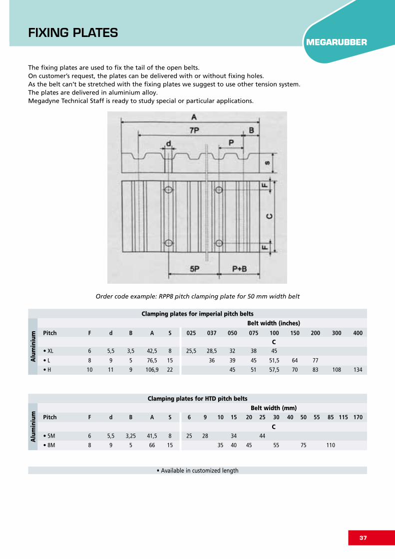
The fixing plates are used to fix the tail of the open belts.On customer’s request, the plates can be delivered with or without fixing holes.As the belt can’t be stretched with the fixing plates we suggest to use other tension system.The plates are delivered in aluminium alloy.Megadyne Technical Staff is ready to study special or particular applications.
Clamping plates for imperial pitch belts
Belt width (inches)
C
Order code example: RPP8 pitch clamping plate for 50 mm width belt
Alu
min
ium
Clamping plates for HTD pitch belts
Belt width (mm)
C
Alu
min
ium
• Available in customized length
FIXINGPLATES
Pitch F d B A S 025 037 050 075 100 150 200 300 400
Pitch F d B A S 6 9 10 15 20 25 30 40 50 55 85 115 170
• 5M 6 5,5 3,25 41,5 8 25 28 34 44
• 8M 8 9 5 66 15 35 40 45 55 75 110
• XL 6 5,5 3,5 42,5 8 25,5 28,5 32 38 45
• L 8 9 5 76,5 15 36 39 45 51,5 64 77
• H 10 11 9 106,9 22 45 51 57,5 70 83 108 134

3840
USEFUL FORMULAS AND CONVERSION TABLE
To convert from to multiply by
CV HP 0,9863201
CV kcal/h 63,24151
CV W 735,4988
CV kW 0,7354988
CV kgf m/s 75
CV lbf ft/s 542,476
HP CV 1,01387
HP kcal/h 641,1865
HP W 745,6999
HP kW 0,7456999
HP kgf m/s 76,04022
HP lbf ft/s 550
in m 0,0254
in cm 2,54
in mm 25,4
in ft 0,083
in2 m2 0,00064516
in2 cm2 6,4516
in2 mm2 645,16
in2 ft2 0,006944444
in3 m3 1,63871·10-5
in3 cm3 16,38706
in3 mm3 16387,06
in3 ft3 0,000578704
To convert from to multiply by
J CV h 3,77673·10-7
J HP h 3,72506·10-7
J kWh 2,77778·10-7
kg lb 2,204623
kgf N 9,80665
kgf lbf 2,204623
kgf m/s CV 0,01333333
kgf m/s W 9,80665
kgf m/s kW 0,00980665
kW CV 1,359622
kW kcal/h 859,8452
kW W 1000
kW kgf m/s 101,9716
kW lbf ft/s 737,5621
lb kg 0,4535924
lb kgf 0,4535924
lb N 4,448222
N kgf 0,1019716
N lbf 0,2248089
W CV 0,001359622
W HP 0,001341022
W kcal/h 0,8598452
W kW 0,001
W kgf m/s 0,1019716
W lbf ft/s 0,7375621
SPEED
V : peripheral speed [m/s]n1 : rotation speed [RPM]d1 : pulley diameter [mm]
POWER
P : power [kW]Fu : peripheral force [N]Mt : drive torque [Nm]n1 : rotation speed [RPM]d1 : pulley diameter [mm]
FORCES AND TORQUE
Fu : peripheral force [N]Mt : drive torque [Nm]P : power [kW]n1 : rotation speed [RPM]d1 : pulley diameter [mm]V : peripheral speed [m/s]
V= d1·n1
19100n1=
V·19100 d1
Fu= 19,1·106·Pd1·n1
Mt= P·9550
n1
P= Fu·d1·n1
19,1·106P=
Mt·n1
9550P=
Fu·V1000
Mt= Fu·d1
2000Mt=
P·d1
2·V
Fu= 2000·Mt
d1
Fu= P·103
d1
d1= V·19100
n1
MEGARUBBERUSEFULFORMULASANDCONVERSIONTABLE

39
The data given in this catalogue are updated at the day of printing and are not intended as a guarantee: Megadyne S.p.A. reserves the right to modify the characteristics of the belts described herein without any prior notice.

Graphic byImmagine 3000 - Turin
Edition October 2010

ME
GA
RU
BB
ER
Ru
bb
er o
pe
n-e
nd
tim
ing
be
lts
MEGADYNE IS LOCATED IN
MATHI (ITALY) *TURIN (ITALY)VENICE (ITALY)MILAN (ITALY) *MINSK (BELARUS)PRAGUE (CZECH REPUBLIC)PARIS (FRANCE) * ST. JEAN DE MAURIENNE (FRANCE) *LION (FRANCE)BORCHEN (GERMANY)ULM (GERMANY) *BUDAPEST (HUNGARY)BYDGOSZCZ (POLAND)BARCELONA (SPAIN) *DUDLEY (UK)STOCKHOLM (SWEDEN)FOSHAN (CHINA)SHANGHAI (CHINA)QINGDAO (CHINA) *DUBAI (UAE)PINEVILLE-NC (USA) *SAO PAULO (BRASIL)NINGBO (CHINA)*
JASON IS LOCATED IN
NEW JERSEYILLINOISCALIFORNIAFLORIDATEXASOREGONQUEBECONTARIOALBERTAMEXICOBRASILSOUTH CAROLINA *
* MANUFACTURING FACILITIES
MEGADYNE HEADQUARTERVia Trieste 16 - 10075 Mathi (TO) - [email protected] - www.megadyne.it
ww
w.im
mag
ine3
000.
it


