
2021 3 5 6 10 ( ) 3000 3000 3000 3000 3000 3000 3000 3000 ...
MedWeld 3000 Catalog Revision 8 July 2002
MedWeld 3000 Series Welding Controls Technical Reference Catalog
Medar is a brand name for welding controls belonging to the Welding Technology Corporation – the world’s largest supplier of resistance welding controls and innovator for resistance welding technologies. http://www.weldtechcorp.com
MedWeld 3000 Catalog Revision 8 July 2002
Table of Content MedWeld 3000 Series Welding Controls ................................................................................... 1 Table of Content........................................................................................................................ 2 Resistance Welding Application................................................................................................ 5
Part and Model Numbers .................................................................................................................6 Configurations and Packages ...........................................................................................................8
Other available platforms for integrators: .....................................................................................8 What type of package to order? .......................................................................................................8
Kit Format ..................................................................................................................................8 Remote Enclosures......................................................................................................................8 Integrated Welding Systems ........................................................................................................8
MedWeld 3005 Kits ................................................................................................................... 9 Single Phase Circuit Boards..............................................................................................................9 Cascade Circuit Boards ....................................................................................................................9
Note on Current Monitoring for AC and 3-Phase to DC Controls: ....................................................9 Single Phase Power Module ...........................................................................................................10 Tripack Multi-Phase Power Modules................................................................................................11 Multi Timer and Cascade Modules ..................................................................................................12 Interface Cables............................................................................................................................13 Door Port Kits ...............................................................................................................................14 Integrator’s Documentation Kits.....................................................................................................14 Circuit Breaker with Operator Handle Kits .......................................................................................15 Isolation Contactor Kits .................................................................................................................15 Power Bus Bar Kits........................................................................................................................15
Remote Power Enclosure Solutions ........................................................................................ 16 Note on Current Monitoring for AC and 3-Phase to DC Controls: ..................................................16
Single and Dual Remote Cabinet ....................................................................................................17 Tripack Remote Cabinet ................................................................................................................18 Six-Pack Remote Cabinet...............................................................................................................19
Integrated Single-Phase Weld Control Enclosure Solution .................................................... 20 Note on Current Monitoring for AC and 3-Phase to DC Controls: ..................................................20
MedWeld 3015..............................................................................................................................21 MedWeld 3025..............................................................................................................................22 MedWeld 3035..............................................................................................................................23 MedWeld 3045..............................................................................................................................24 MedWeld 3055..............................................................................................................................25 MedWeld 3065..............................................................................................................................26 MedWeld 3075..............................................................................................................................27 MedWeld 3095..............................................................................................................................28 Options and Accessories for Integrated Solutions ............................................................................29
Circuit Breakers with Operating Handles .....................................................................................29 Isolation Contactors ..................................................................................................................29 SCR Upgrades...........................................................................................................................30 Power Transformers..................................................................................................................30 Special Multitap Power Transformers..........................................................................................30 DC Power Supplies ....................................................................................................................30 Power Bus Bars.........................................................................................................................31 Multi-pin Connectors and Terminal Strips....................................................................................31 Door Port Access Kit..................................................................................................................31 Water Flow Switches and Valves ................................................................................................31 Secondary Current Monitoring Kits .............................................................................................31

MedWeld 3000 Catalog Revision 8 July 2002
Allen-Bradley TM Components.................................................................................................. 32 Fixed I/O Configuration .................................................................................................................32 Flexible I/O Configurations ............................................................................................................32 Chassis and Interconnect Cables....................................................................................................33 Power Supplies .............................................................................................................................33 Modular Processors .......................................................................................................................34 Memory Modules...........................................................................................................................34 Input and Output Modules.............................................................................................................35 Remote I/O and Device Net Modules..............................................................................................36 Analog and Encoder Modules .........................................................................................................36
Cascade Weld Control Solutions ............................................................................................. 37 Single Timer - Multiple SCR Systems ..............................................................................................38 Multiple Timers - Multiple SCR Systems ..........................................................................................38 Model Number Review for Cascade Systems ...................................................................................39
Mid-Frequency to DC (MFDC) Weld Control Solutions............................................................ 40 Benefits of MFDC Welding Systems ................................................................................................41 MF600 Inverter for all Steel Caliber Range......................................................................................42
MF600 Inverter Kit ....................................................................................................................42 MF1200 Inverter for Aluminum Welding Caliber Range ....................................................................43
MF1200 Inverter Kit ..................................................................................................................43 Milli-Second Interface Option .........................................................................................................44 Medar MFDC System with Millisecond Interface...............................................................................45
MedWeld 3005 3-Phase to DC Weld Controls ......................................................................... 46 Single MedWeld 3-Phase System....................................................................................................46 Multiple MedWeld 3-Phase Systems................................................................................................47 Model Numbers for 3-Phase Systems .............................................................................................48
Note on Current Monitoring for AC and 3-Phase to DC Controls: ..................................................48 MedWeld 3035-WTP......................................................................................................................49 MedWeld 3065-WTP......................................................................................................................50 MedWeld 3075-WTP......................................................................................................................51 MedWeld 3095-WTP......................................................................................................................52 Model Number Review for 3-Phase Systems ...................................................................................53
Safety Ground Fault Systems for Manually Operated Transguns ........................................... 54 2-Level Detection System ..............................................................................................................55
2-Level Manual Gun Safety Protection System Option Installed ....................................................55 “Touchsafe” Switch & Power Supply Installed .............................................................................55
3-Level Detection System ..............................................................................................................56 3-level Manual Gun Safety Protection System Installed................................................................56
Programming Devices for MedWeld Controls ......................................................................... 57 DEP100s.......................................................................................................................................57 DP200s ........................................................................................................................................58 Network Power Pack .....................................................................................................................59
Brad Harrison Cable for Network Power Pack ..............................................................................59 Medar Networking Products ................................................................................................... 60
Weld Support Systems ..................................................................................................................60 WebVIEW.................................................................................................................................60
Medar WebVIEW (Phase 1)....................................................................................................61 WebVIEW Phase 1 Features: .................................................................................................61 Sample page of WebVIEW.....................................................................................................61
WebVIEW – Phase 2 .................................................................................................................62 WebVIEW Phase 2 Additional Features:..................................................................................62
Weld Support Systems (Bank System Software)..............................................................................63
MedWeld 3000 Catalog Revision 8 July 2002
Sizing Circuit Breaker and Isolation Contactors ..................................................................... 64 RULES FOR SELECTING CIRCUIT BREAKER FRAME SIZES ...............................................................64
DISCLAIMER:............................................................................................................................64 ASSUMPTIONS: ........................................................................................................................64
PART 1: CIRCUIT BREAKER MINIMUM FRAME SIZE SELECTION GUIDE ...................................65 PART 2: MAGNETIC TRIP RANGE SELECTION.........................................................................66
RULES FOR SIZING ISOLATION CONTACTORS ...............................................................................67 DISCLAIMER:............................................................................................................................67 ASSUMPTIONS: ........................................................................................................................67
PART 1:CALCULATION OF AVERAGE CURRENT DRAW PER WELDING TRANSFORMER ..............68 PART 2: ISOLATION CONTACTOR CURRENT RATING SELECTION BASED ON TRANSFORMER CONNECTION. ......................................................................................................................69
Directory of Resources ............................................................................................................ 71 WTC - Corporate Office .................................................................................................................71 WTC Automotive...........................................................................................................................71 WTC Canada.................................................................................................................................71 Technitron Industrial Division ........................................................................................................71 Industrial Technical Services Division .............................................................................................71
Quality ..................................................................................................................................... 72 QS 9000 with TE Supplement ........................................................................................................72 Acknowledgements .......................................................................................................................72
MedWeld 3000July 2002
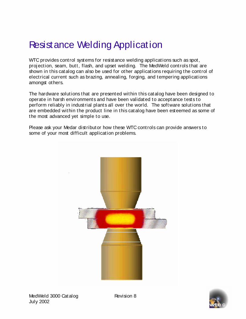
Resistance Welding Application WTC provides control systems for resistance welding applications such as spot, projection, seam, butt, flash, and upset welding. The MedWeld controls that are shown in this catalog can also be used for other applications requiring the control of electrical current such as brazing, annealing, forging, and tempering applications amongst others. The hardware solutions that are presented within this catalog have been designed to operate in harsh environments and have been validated to acceptance tests to perform reliably in industrial plants all over the world. The software solutions that are embedded within the product line in this catalog have been esteemed as some of the most advanced yet simple to use. Please ask your Medar distributor how these WTC controls can provide answers to some of your most difficult application problems.
Catalog Revision 8

MedWeld 3000 Catalog Revision 8 July 2002
Part and Model Numbers There are various numbers that can identify a Medar welding control. The part number is referenced on the serial tag. This number appears such as 952-1196 as an example, which identifies item specific designs with distinct bills of materials. Please use the part number if you wish to re-order an identical control. As a general guide to the composition of a welding control, a model number is also provided. It is normal however for various controls of differing part numbers to share a common model number. The following describes the model number scheme. 3095-12=1200-4003-1=#5-4806
The first four digits signify a weld processor and enclosure model. The 30xx means that it is an integration control. The xx9x signifies a specific enclosure (see MedWeld 3095 in table of content). The xxx5 signifies that the weld processor is integrated in the Allen-Bradley SLC 500 rack.
The next set of digits (12=1200) signifies the power switches and their configurations. As shown, the 12=1200 signifies that there are twelve welding processors each with their own 1200 amperes SCRs. A model numbers that indicates 12C=1200 would mean that there is one welding processor being shared by twelve 1200 amp SCRs in cascading fashion. A model number that indicates 4W12C=1200 would mean that there is four welding processors being shared by twelve 1200 amp SCRs in cascading fashion. A model number that indicates WTP=1750 would mean that there is a welding processor controlling a 3-Phase to DC power distribution where the SCRs are rated at 1750 amperes. A model number that indicates 4WTP=3300 would mean that there is four welding processors each controlling a 3-Phase to DC power distribution where the SCRs are rated at 3300 amperes. A model number that indicates 2W4TP=3300 would mean that there are two welding processors controlling four 3-Phase to DC power distribution where the SCRs are rated at 3300 amperes. A model number that indicates 1=MF300 would mean that one welding processor is controlling a 300 ampere mid frequency inverter.
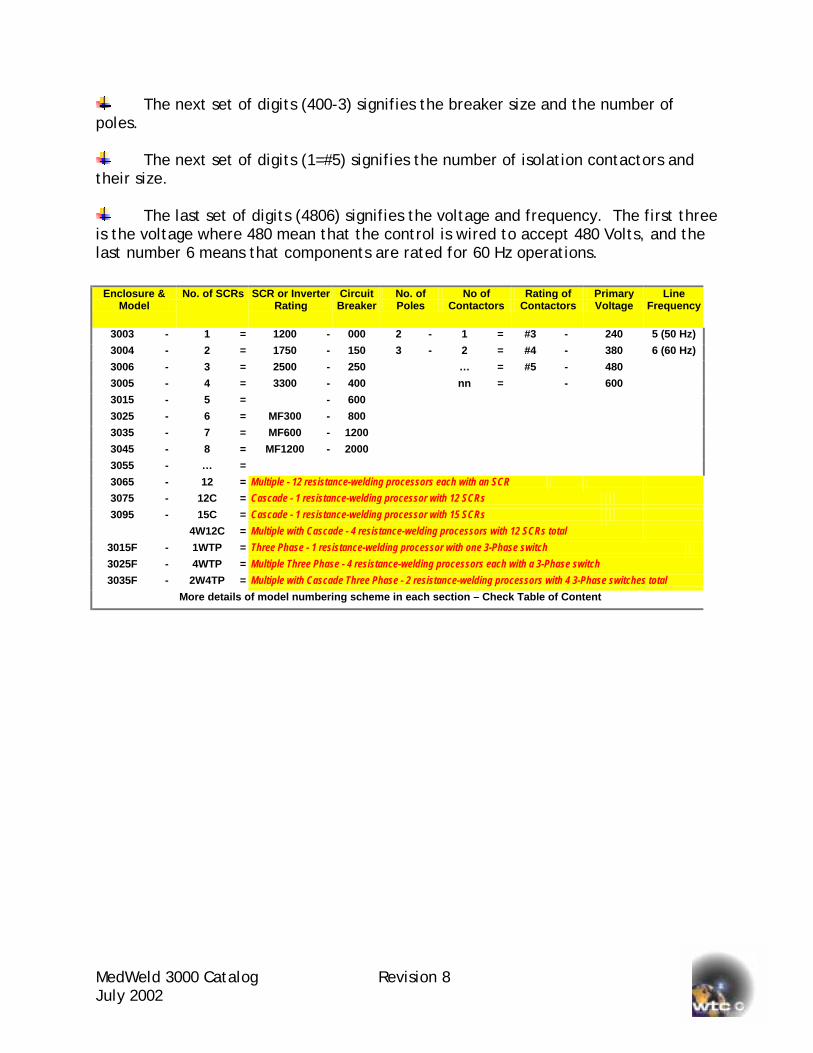
The next set of digits (400-3) signifies the breaker size and the number of poles.
The next set of digits (1=#5) signifies the number of isolation contactors and their size.
The last set of digits (4806) signifies the voltage and frequency. The first three is the voltage where 480 mean that the control is wired to accept 480 Volts, and the last number 6 means that components are rated for 60 Hz operations.
Enclosure & Model
No. of SCRs SCR or Inverter Rating
Circuit Breaker
No. of Poles
No of Contactors
Rating of Contactors
Primary Voltage
Line Frequency
3003 - 1 = 1200 - 000 2 - 1 = #3 - 240 5 (50 Hz)
3004 - 2 = 1750 - 150 3 - 2 = #4 - 380 6 (60 Hz)
3006 - 3 = 2500 - 250 … = #5 - 480
3005 - 4 = 3300 - 400 nn = - 600
3015 - 5 = - 600
3025 - 6 = MF300 - 800
3035 - 7 = MF600 - 1200
3045 - 8 = MF1200 - 2000
3055 - … =
3065 - 12 = Multiple - 12 resistance-welding processors each with an SCR 3075 - 12C = Cascade - 1 resistance-welding processor with 12 SCRs 3095 - 15C = Cascade - 1 resistance-welding processor with 15 SCRs
4W12C = Multiple with Cascade - 4 resistance-welding processors with 12 SCRs total 3015F - 1WTP = Three Phase - 1 resistance-welding processor with one 3-Phase switch 3025F - 4WTP = Multiple Three Phase - 4 resistance-welding processors each with a 3-Phase switch 3035F - 2W4TP = Multiple with Cascade Three Phase - 2 resistance-welding processors with 4 3-Phase switches total
More details of model numbering scheme in each section – Check Table of Content
MedWeld 3000 Catalog Revision 8 July 2002
MedWeld 3000 Catalog Revision 8 July 2002 Page 8 of 72
Configurations and Packages The MedWeld 3000 Series resistance welding controls have welding processor boards that integrate into the hardware platform of machine or robotic controllers. This eliminates redundant hardware such as input and output modules, multi-conductor cables, terminal points, and rack assemblies. This makes the overall system more reliable in its production environment.
MedWeld 3003 – integrates with Nachi Robotics Systems – AR & AW Robots MedWeld 3004 – integrates with Fanuc Robotics Systems – RJ3 Robot MedWeld 3005 – integrates with Allen-Bradley – 1747 SLC 500 MedWeld 3006 – integrates with Motoman Robotics Systems – XRC Robot
Other available platforms for integrators:
IBM PC ISA Half slot bus VME bus in 6U form factor Compact PCI 6U form factor PC104 bus compatible
What type of package to order? There are three types of packages that can be obtained: kit format, remote enclosure format, and the fully integrated system format. The MedWeld 3003, 3004 and 3006 come only in the remote enclosure format whereas the MedWeld 3005 comes in all types of packages.
Kit Format The MedWeld 3005 can be purchased in kit format. Kits are for integrators who assemble their own control enclosures and want to add Medar modules within these enclosures to provide resistance-welding capabilities. Please call should another type of kit not listed in this publication suit your needs better. An integrator who purchased a MedWeld 3005 Tripack integrator’s kit shown has assembled the control system that is shown on the cover. The circuit breaker with its operating handle, the isolation contactor, and the power bus bars are also available in kits.
Remote Enclosures All MedWeld 3000 Series controls can be purchased in remote enclosure packages. This package allows the separation of high voltages present in welding controls from the controls system. A full description of the remote enclosure concept is described on pages 16 and 18.
Integrated Welding Systems OEMs and users can acquire a fully integrated resistance welding system from Medar. There are various standard configurations that are shown in this catalog. Please call should you need a customized system that is not shown in this publication.
MedWeld 3000 Catalog July 2002
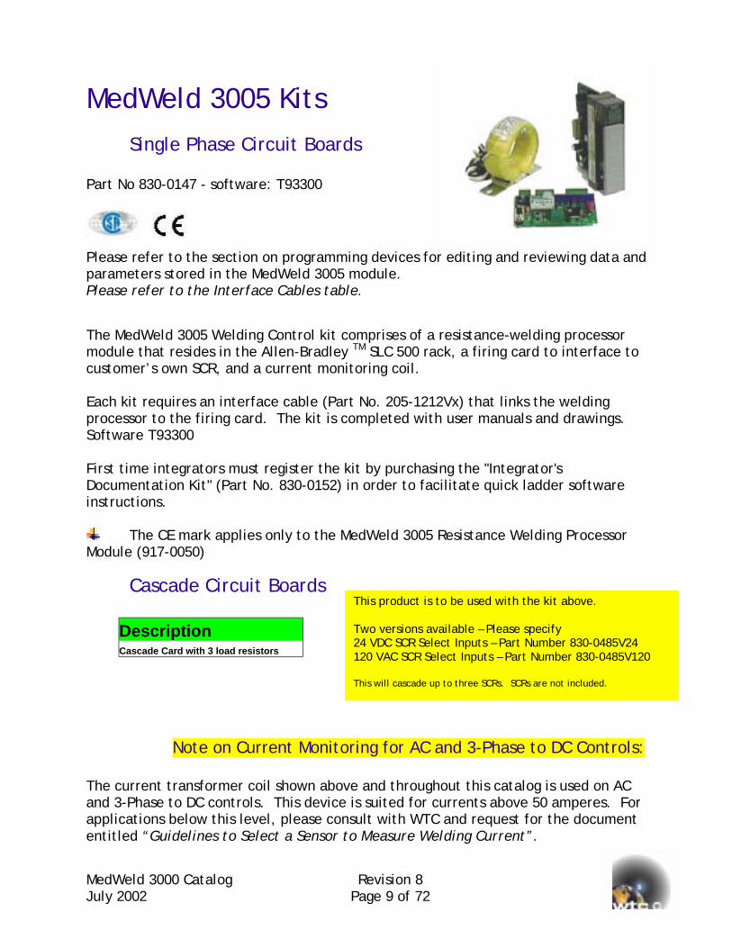
MedWeld 3005 Kits Single Phase Circuit Boards
Part No 830-0147 - software: T93300
Please refer to the section on programming devices for editing and reviewing data and parameters stored in the MedWeld 3005 module. Please refer to the Interface Cables table.
The MedWeld 3005 Welding Control kit comprises of a resistance-welding processor module that resides in the Allen-Bradley TM SLC 500 rack, a firing card to interface to customer’s own SCR, and a current monitoring coil. Each kit requires an interface cable (Part No. 205-1212Vx) that links the welding processor to the firing card. The kit is completed with user manuals and drawings. Software T93300 First time integrators must register the kit by purchasing the "Integrator's Documentation Kit" (Part No. 830-0152) in order to facilitate quick ladder software instructions.
The CE mark applies only to the MedWeld 3005 Resistance Welding Processor Module (917-0050)
Cascade Circuit Boards
Description Cascade Card with 3 load resistors
Note on Current Monito The current transformer coil shown abovand 3-Phase to DC controls. This deviceapplications below this level, please conentitled “Guidelines to Select a Sensor t
This product is to be used with the kit above. Two versions available – Please specify 24 VDC SCR Select Inputs – Part Number 830-0485V24 120 VAC SCR Select Inputs – Part Number 830-0485V120 This will cascade up to three SCRs. SCRs are not included.
Revision 8 Page 9 of 72
ring for AC and 3-Phase to DC Controls:
e and throughout this catalog is used on AC is suited for currents above 50 amperes. For sult with WTC and request for the document o Measure Welding Current”.

MJ
Single Phase Power Module Part No 830-0209 – software: T93300 Part No 830-0210 – software: T93301 Part No 830-0409 – software: T93308
Please refer to the section on programming devices for editing and reviewing data and parameters stored in the MedWeld 3005 module. Please refer to the Interface Cables table.
The MedWeld 3005 resistance welding processor module is a welding processor that fits into the Allen-Bradley TM SLC500 rack system. The power module (dimensions 8 D x 12 W x 5 H (203mm x 305mm x 127mm)) is equipped with a 1200 amp SCR, a firing module and a current monitoring sensor. Each kit requires an interface cable (Part No. 205-1212Vx) that links the welding processor to the power module. The kit is completed with user manuals and drawings. Software T93300 First time integrators must register the kit by purchasing the "Integrator's Documentation Kit" (Part No. 830-0152) in order to facilitate quick ladder software instructions.
The CE mark applies only to the MedWeld 3005 Resistance Welding Processor Module (917-0050)
The single power module viewed from the bottom. The current monitoring coil that surrounds the SCR’s tang provides welding data information to the welding processor shown on the left. Choose an appropriate length of interface cable listed in the table on following pages.
WTC welding controls provide a load resistor across the welding transformer. This resistor assures proper SCR firing and transient voltage suppression under all operating conditions. The load resistor supplied as standard equipment is designed for spot welding or short duration seam welding use with a maximum weld time of 5 seconds and a maximum duty cycle of 33%. If your welding application involves weld times longer than 5 seconds per weld or an overall duty cycle exceeding 33%, a larger load resistor is required. Please contact the factory or your sales representative to obtain the correct load resistor for your application.
edWeld 3000 Catalog Revision 8 uly 2002 Page 10 of 72

Tripack Multi-Phase Power Modules Part No. 830-0168V2 (distributed over three phases) Part No. 830-0168 (distributed over one phase) Software T93300
Please refer to the section on programming devices for editing and reviewing data and parameters stored in the MedWeld 3005 module.
Please refer to the Interface Cables table.
Tripack power module viewed from the bottom. The return line from the weld transformer must go through the appropriate current monitoring coil thatis found beneath the SCRs.
MJ
The Tripack power module (dimension 15 D x 14 W x 9 H (380mm x 356mm x 230mm)) is recommended for welding stations that require multiple controls in limited space. The power module has three sets of 1200 amp SCRs, firing boards and current monitoring sensors. Three intelligent MedWeld 3005 resistance-welding processor modules are included for installation in the Allen-Bradley TM SLC 500 rack. This kit requires three interface cables (Part No. 205-1212Vx) purchased separately. The kit is completed with user manuals and drawings. Software T93300 First time integrators must register the kit by purchasing the "Integrator's Documentation Kit" (Part No. 830-0152) in order to facilitate quick ladder software instructions.
The CE mark applies only to the MedWeld 3005 Resistance Welding Processor Module (917-0050)
WTC welding controls provide a load resistor across the welding transformer. This resistor assures proper SCR firing and transient voltage suppression under all operating conditions. The load resistor supplied as standard equipment is designed for spot welding or short duration seam welding use with a maximum weld time of 5 seconds and a maximum duty cycle of 33%. If your welding application involves weld times longer than 5 seconds per weld or an overall duty cycle exceeding 33%, a larger load resistor is required. Please contact the factory or your sales representative to obtain the correct load resistor for your application.
edWeld 3000 Catalog Revision 8 uly 2002 Page 11 of 72
MedWeld 3000 Catalog Revision 8 July 2002 Page 12 of 72
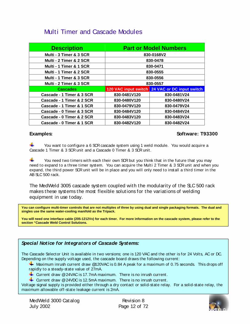
Multi Timer and Cascade Modules
Description Part or Model Numbers Multi - 3 Timer & 3 SCR 830-0168V2 Multi - 2 Timer & 2 SCR 830-0478 Multi - 1 Timer & 1 SCR 830-0471 Multi - 1 Timer & 2 SCR 830-0555 Multi - 1 Timer & 3 SCR 830-0556 Multi - 2 Timer & 3 SCR 830-0557
Cascades 120 VAC input switch 24 VAC or DC input switch Cascade - 1 Timer & 3 SCR 830-0481V120 830-0481V24 Cascade - 1 Timer & 2 SCR 830-0480V120 830-0480V24 Cascade - 1 Timer & 1 SCR 830-0479V120 830-0479V24 Cascade - 0 Timer & 3 SCR 830-0484V120 830-0484V24 Cascade - 0 Timer & 2 SCR 830-0483V120 830-0483V24 Cascade - 0 Timer & 1 SCR 830-0482V120 830-0482V24
Examples: Software: T93300
You want to configure a 6 SCR cascade system using 1 weld module. You would acquire a Cascade 1 Timer & 3 SCR unit and a Cascade 0 Timer & 3 SCR unit.
You need two timers with each their own SCR but you think that in the future that you may need to expand to a three timer system. You can acquire the Multi 2 Timer & 3 SCR unit and when you expand, the third power SCR unit will be in place and you will only need to install a third timer in the AB SLC 500 rack. The MedWeld 3005 cascade system coupled with the modularity of the SLC 500 rack makes these systems the most flexible solutions for the variations of welding equipment in use today.
You can configure multi-timer controls that are not multiples of three by using dual and single packaging formats. The dual and singles use the same water-cooling manifold as the Tripack. You will need one interface cable (205-1212Vx) for each timer. For more information on the cascade system, please refer to the section “Cascade Weld Control Solutions.
Special Notice for Integrators of Cascade Systems: The Cascade Selector Unit is available in two versions; one is 120 VAC and the other is for 24 Volts, AC or DC. Depending on the supply voltage used, the cascade board draws the following current:
Maximum inrush current draw @120VAC is 0.84 A peak for a maximum of 0.75 seconds. This drops off rapidly to a steady-state value of 27mA.
Current draw @ 24VAC is 17.7mA maximum. There is no inrush current. Current draw @ 24VDC is 12.5mA maximum. There is no inrush current.
Voltage signal supply is provided either through a dry contact or solid-state relay. For a solid-state relay, the maximum allowable off-state leakage current is 2mA.
MedWeld 3000 Catalog Revision 8 July 2002 Page 13 of 72
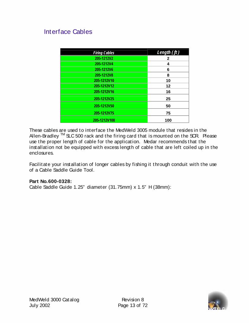
Interface Cables
Firing Cables Length ( ft ) 205-1212V2 2 205-1212V4 4 205-1212V6 6 205-1212V8 8
205-1212V10 10 205-1212V12 12 205-1212V16 16
205-1212V25 25
205-1212V50 50
205-1212V75 75
205-1212V100 100 These cables are used to interface the MedWeld 3005 module that resides in the Allen-Bradley TM SLC 500 rack and the firing card that is mounted on the SCR. Please use the proper length of cable for the application. Medar recommends that the installation not be equipped with excess length of cable that are left coiled up in the enclosures. Facilitate your installation of longer cables by fishing it through conduit with the use of a Cable Saddle Guide Tool. Part No.600-0328: Cable Saddle Guide 1.25” diameter (31.75mm) x 1.5” H (38mm):
MedWeld 3000 Catalog Revision 8 July 2002 Page 14 of 72
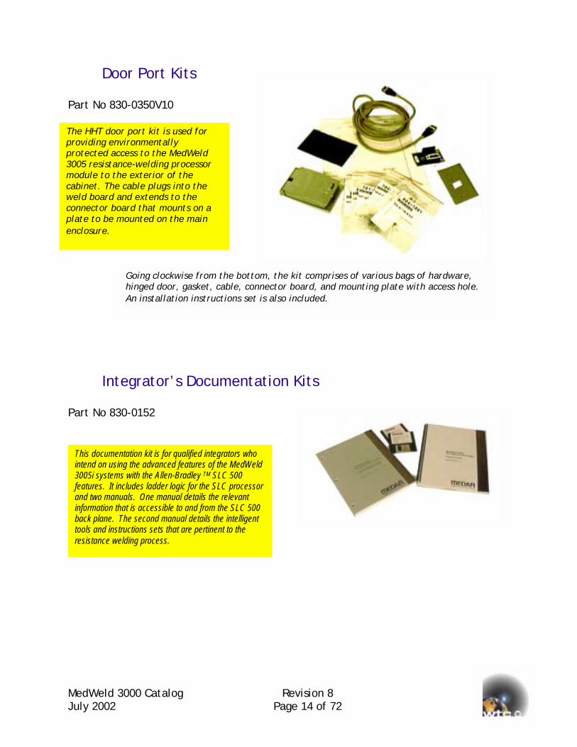
Door Port Kits Part No 830-0350V10
Integrator’s Documentation Kits Part No 830-0152
The HHT door port kit is used for providing environmentally protected access to the MedWeld 3005 resistance-welding processor module to the exterior of the cabinet. The cable plugs into the weld board and extends to the connector board that mounts on a plate to be mounted on the main enclosure.
Going clockwise from the bottom, the kit comprises of various bags of hardware, hinged door, gasket, cable, connector board, and mounting plate with access hole. An installation instructions set is also included.
This documentation kit is for qualified integrators who intend on using the advanced features of the MedWeld 3005i systems with the Allen-Bradley TM SLC 500 features. It includes ladder logic for the SLC processor and two manuals. One manual details the relevant information that is accessible to and from the SLC 500 back plane. The second manual details the intelligent tools and instructions sets that are pertinent to the resistance welding process.
MedWeld 3000 Catalog Revision 8 July 2002 Page 15 of 72
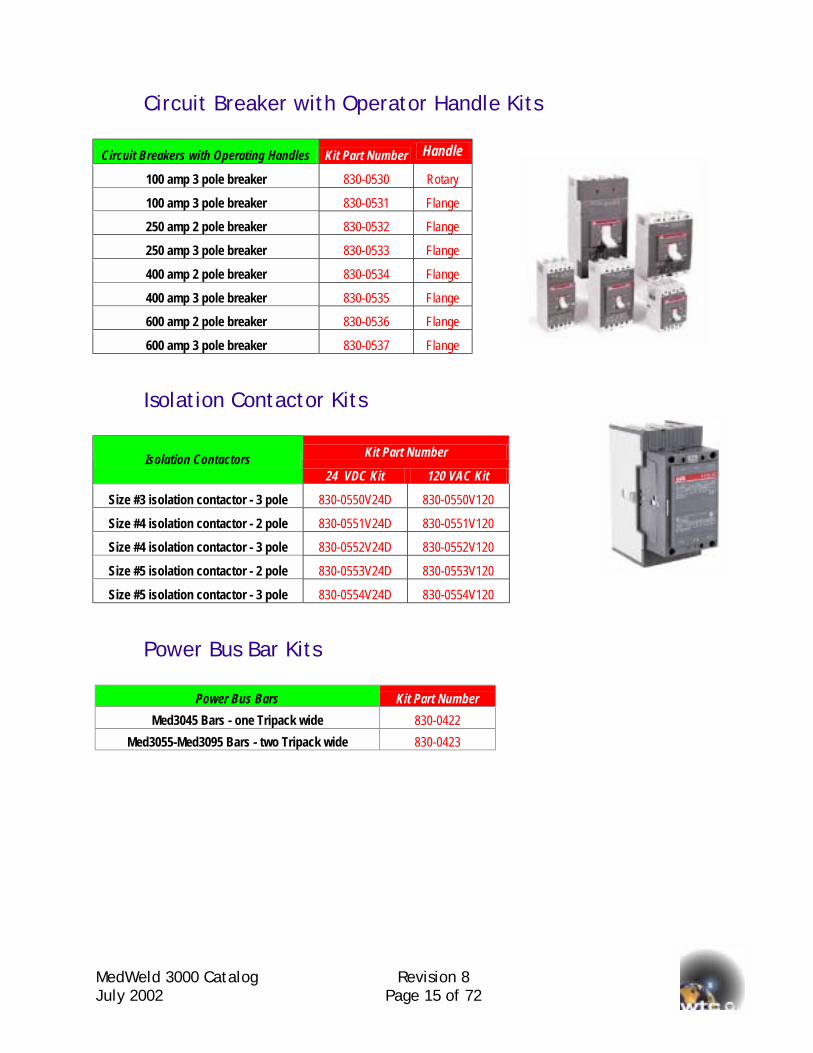
Circuit Breaker with Operator Handle Kits
Circuit Breakers with Operating Handles Kit Part Number Handle
100 amp 3 pole breaker 830-0530 Rotary
100 amp 3 pole breaker 830-0531 Flange
250 amp 2 pole breaker 830-0532 Flange
250 amp 3 pole breaker 830-0533 Flange
400 amp 2 pole breaker 830-0534 Flange
400 amp 3 pole breaker 830-0535 Flange
600 amp 2 pole breaker 830-0536 Flange
600 amp 3 pole breaker 830-0537 Flange
Isolation Contactor Kits
Kit Part Number Isolation Contactors 24 VDC Kit 120 VAC Kit
Size #3 isolation contactor - 3 pole 830-0550V24D 830-0550V120
Size #4 isolation contactor - 2 pole 830-0551V24D 830-0551V120
Size #4 isolation contactor - 3 pole 830-0552V24D 830-0552V120
Size #5 isolation contactor - 2 pole 830-0553V24D 830-0553V120
Size #5 isolation contactor - 3 pole 830-0554V24D 830-0554V120
Power Bus Bar Kits
Power Bus Bars Kit Part Number Med3045 Bars - one Tripack wide 830-0422
Med3055-Med3095 Bars - two Tripack wide 830-0423
MedWeld 3000 Catalog Revision 8 July 2002 Page 16 of 72
Remote Power Enclosure Solutions Available in AC or MFDC models! The remote power enclosures are suitable for integrated welding control solutions such as the MedWeld 3005 (Allen-Bradley TM SLC500 System), the MedWeld 3003 (Nachi Robotics TM System), the MedWeld 3004 (Fanuc Robotics TM System) and the MedWeld 3006 (Motoman Robotics). It is selected where the user requires a separation of the higher welding bus voltages from the control circuits. The remote enclosure incorporates single or multiple SCRs and welding current sensors. It is also available with optional circuit breakers and isolation contactors. The intelligent resistance-welding processor module(s) is shipped with the enclosure to be installed in the main processor rack within the robot or SLC control. Each SCR firing module requires an interface cable to link it to the welding processor. Please refer to the cable reference table. First Time users of the MedWeld 3005 system should register by purchasing the "Integrator's Documentation Kit" (Part No. 830-0152) in order to facilitate quick ladder software instructions.
Note on Current Monitoring for AC and 3-Phase to DC Controls: The current transformer coil shown above and throughout this catalog is used on AC and 3-Phase to DC controls. This device is suited for currents above 50 amperes. For applications below this level, please consult with WTC and request for the document entitled “Guidelines to Select a Sensor to Measure Welding Current”.
MJ
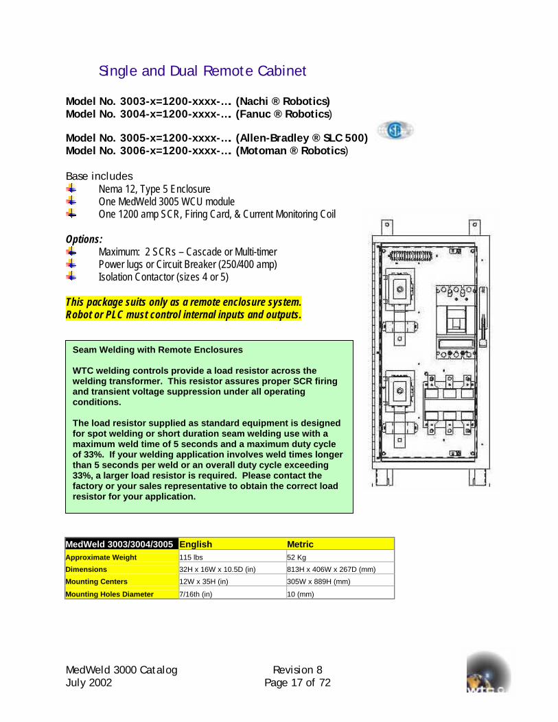
Single and Dual Remote Cabinet Model No. 3003-x=1200-xxxx-…. (Nachi ® Robotics) Model No. 3004-x=1200-xxxx-…. (Fanuc ® Robotics)
Model No. 3005-x=1200-xxxx-…. (Allen-Bradley ® SLC 500) Model No. 3006-x=1200-xxxx-…. (Motoman ® Robotics) Base includes
Nema 12, Type 5 Enclosure One MedWeld 3005 WCU module One 1200 amp SCR, Firing Card, & Current Monitoring Coil
Options:
Maximum: 2 SCRs – Cascade or Multi-timer Power lugs or Circuit Breaker (250/400 amp) Isolation Contactor (sizes 4 or 5)
This package suits only as a remote enclosure system. Robot or PLC must control internal inputs and outputs. MA
D
M
M
Seam Welding with Remote Enclosures WTC welding controls provide a load resistor across the welding transformer. This resistor assures proper SCR firing and transient voltage suppression under all operating conditions. The load resistor supplied as standard equipment is designed for spot welding or short duration seam welding use with a maximum weld time of 5 seconds and a maximum duty cycle of 33%. If your welding application involves weld times longer than 5 seconds per weld or an overall duty cycle exceeding 33%, a larger load resistor is required. Please contact the factory or your sales representative to obtain the correct load resistor for your application.
edWeld 3000 Catalog Revision 8 uly 2002 Page 17 of 72
edWeld 3003/3004/3005 English Metric pproximate Weight 115 lbs 52 Kg
imensions 32H x 16W x 10.5D (in) 813H x 406W x 267D (mm)
ounting Centers 12W x 35H (in) 305W x 889H (mm)
ounting Holes Diameter 7/16th (in) 10 (mm)
MedWeld 3000 Catalog Revision 8 July 2002 Page 18 of 72
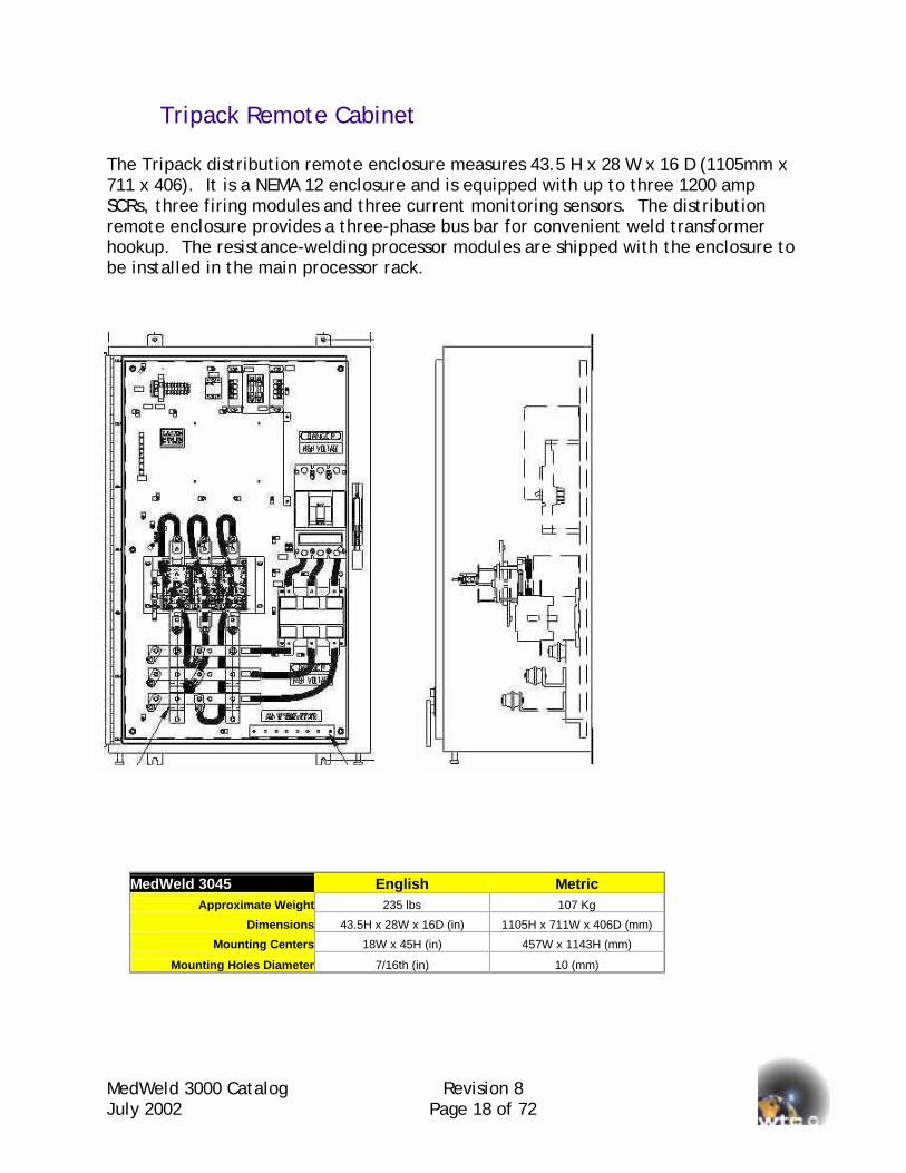
Tripack Remote Cabinet The Tripack distribution remote enclosure measures 43.5 H x 28 W x 16 D (1105mm x 711 x 406). It is a NEMA 12 enclosure and is equipped with up to three 1200 amp SCRs, three firing modules and three current monitoring sensors. The distribution remote enclosure provides a three-phase bus bar for convenient weld transformer hookup. The resistance-welding processor modules are shipped with the enclosure to be installed in the main processor rack.
MedWeld 3045 English Metric Approximate Weight 235 lbs 107 Kg
Dimensions 43.5H x 28W x 16D (in) 1105H x 711W x 406D (mm)
Mounting Centers 18W x 45H (in) 457W x 1143H (mm)
Mounting Holes Diameter 7/16th (in) 10 (mm)
MedWeld 3000 Catalog Revision 8 July 2002 Page 19 of 72
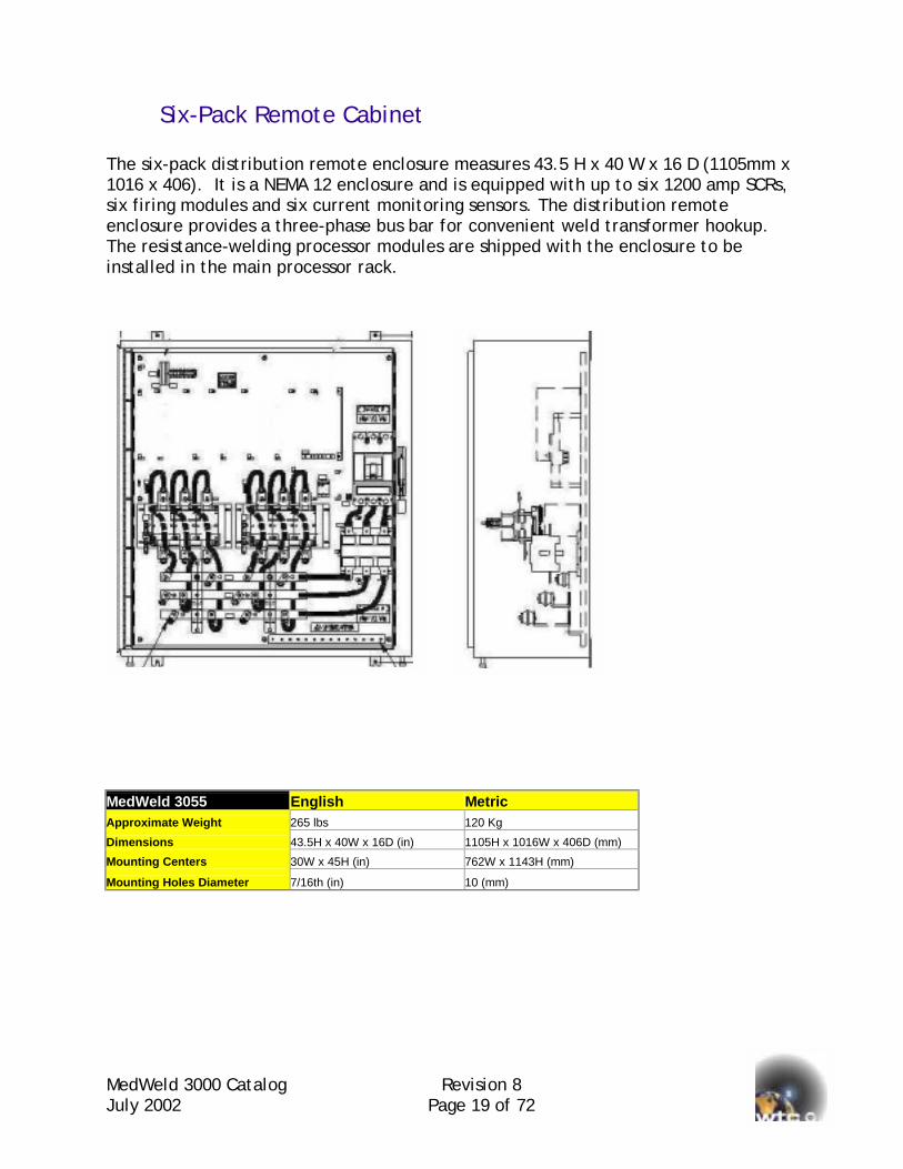
Six-Pack Remote Cabinet The six-pack distribution remote enclosure measures 43.5 H x 40 W x 16 D (1105mm x 1016 x 406). It is a NEMA 12 enclosure and is equipped with up to six 1200 amp SCRs, six firing modules and six current monitoring sensors. The distribution remote enclosure provides a three-phase bus bar for convenient weld transformer hookup. The resistance-welding processor modules are shipped with the enclosure to be installed in the main processor rack. MedWeld 3055 English Metric Approximate Weight 265 lbs 120 Kg
Dimensions 43.5H x 40W x 16D (in) 1105H x 1016W x 406D (mm)
Mounting Centers 30W x 45H (in) 762W x 1143H (mm)
Mounting Holes Diameter 7/16th (in) 10 (mm)
MeJu
Integrated Single-Phase Weld Control Enclosure Solution The MedWeld 3005 system can be fully configured Welding Control Units (WCU) that is immediately ready for use. It is available in several enclosures in various configurations. There are various standard packages as shown from pages 12 to 16. Should their need to be other customized integrated control packages, please call Medar or its distributor.
Thanapen
Seam Welding with Integrated Enclosures WTC welding controls provide a load resistor across the welding transformer. This resistor assures proper SCR firing and transient voltage suppression under all operating conditions. The load resistor supplied as standard equipment is designed for spot welding or short duration seam welding use with a maximum weld time of 5 seconds and a maximum duty cycle of 33%. If your welding application involves weld times longer than 5 seconds per weld or an overall duty cycle exceeding 33%, a larger load resistor is required. Please contact the factory or your sales representative to obtain the correct load resistor for your application.
dWeld 3000 Catalog Revision 8 ly 2002 Page 20 of 72
Note on Current Monitoring for AC and 3-Phase to DC Controls:
e current transformer coil shown above and throughout this catalog is used on AC d 3-Phase to DC controls. This device is suited for currents above 50 amperes. For plications below this level, please consult with WTC and request for the document titled “Guidelines to Select a Sensor to Measure Welding Current”.
MedWeld 3000 Catalog Revision 8 July 2002 Page 21 of 72
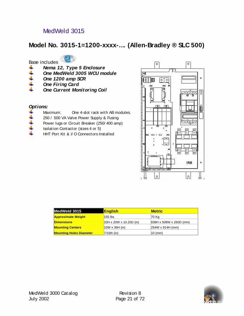
MedWeld 3015 Model No. 3015-1=1200-xxxx-…. (Allen-Bradley ® SLC 500)
Base includes Nema 12, Type 5 Enclosure One MedWeld 3005 WCU module One 1200 amp SCR One Firing Card One Current Monitoring Coil
Options:
Maximum: One 4-slot rack with AB modules. 250 / 500 VA Valve Power Supply & Fusing Power lugs or Circuit Breaker (250/400 amp) Isolation Contactor (sizes 4 or 5) HHT Port Kit & I/O Connectors Installed
MedWeld 3015 English Metric Approximate Weight 155 lbs 70 Kg
Dimensions 33H x 20W x 10.25D (in) 838H x 508W x 260D (mm)
Mounting Centers 10W x 36H (in) 254W x 914H (mm)
Mounting Holes Diameter 7/16th (in) 10 (mm)
MedWeld 3000 Catalog Revision 8 July 2002 Page 22 of 72
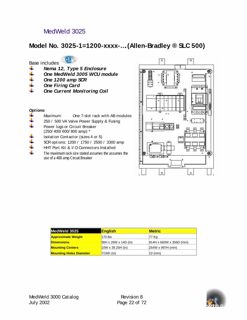
MedWeld 3025 Model No. 3025-1=1200-xxxx-….(Allen-Bradley ® SLC 500)
Base includes Nema 12, Type 5 Enclosure One MedWeld 3005 WCU module One 1200 amp SCR One Firing Card One Current Monitoring Coil
Options:
Maximum: One 7-slot rack with AB modules 250 / 500 VA Valve Power Supply & Fusing Power lugs or Circuit Breaker
(250/400/600/800 amp) * Isolation Contactor (sizes 4 or 5) SCR options: 1200 / 1750 / 2500 / 3300 amp HHT Port Kit & I/O Connectors Installed The maximum rack size stated assumes the assumes the
use of a 400 amp Circuit Breaker
MedWeld 3025 English Metric Approximate Weight 170 lbs 77 Kg
Dimensions 36H x 26W x 14D (in) 914H x 660W x 356D (mm)
Mounting Centers 10W x 39.25H (in) 254W x 997H (mm)
Mounting Holes Diameter 7/16th (in) 10 (mm)
MedWeld 3000 Catalog Revision 8 July 2002 Page 23 of 72
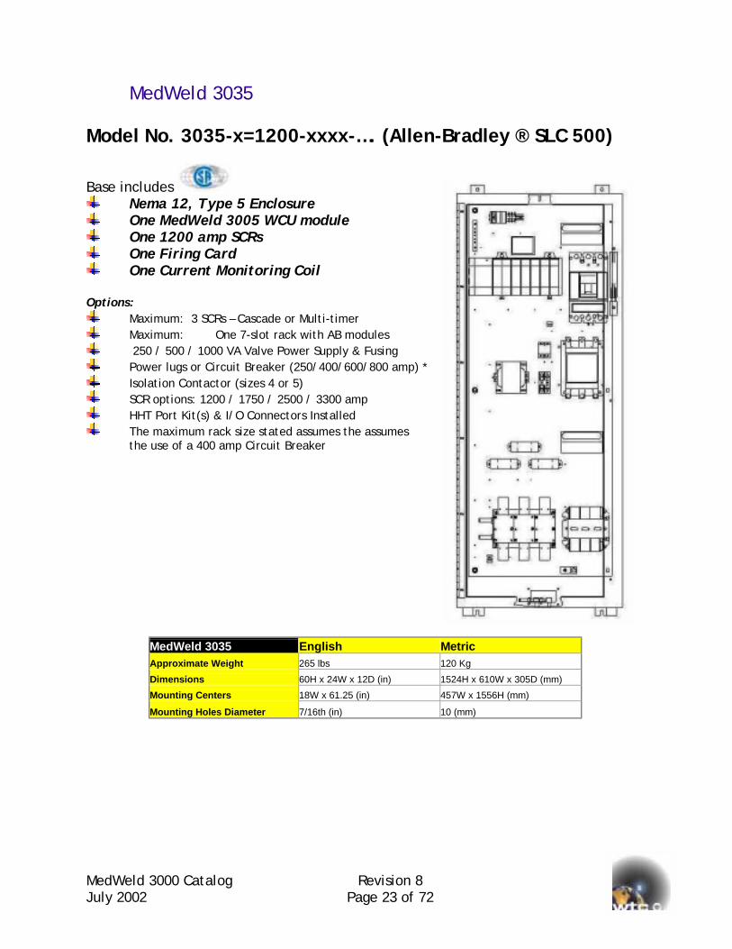
MedWeld 3035 Model No. 3035-x=1200-xxxx-…. (Allen-Bradley ® SLC 500)
Base includes Nema 12, Type 5 Enclosure One MedWeld 3005 WCU module One 1200 amp SCRs One Firing Card One Current Monitoring Coil
Options:
Maximum: 3 SCRs – Cascade or Multi-timer Maximum: One 7-slot rack with AB modules 250 / 500 / 1000 VA Valve Power Supply & Fusing Power lugs or Circuit Breaker (250/400/600/800 amp) * Isolation Contactor (sizes 4 or 5) SCR options: 1200 / 1750 / 2500 / 3300 amp HHT Port Kit(s) & I/O Connectors Installed The maximum rack size stated assumes the assumes
the use of a 400 amp Circuit Breaker
MedWeld 3035 English Metric Approximate Weight 265 lbs 120 Kg
Dimensions 60H x 24W x 12D (in) 1524H x 610W x 305D (mm)
Mounting Centers 18W x 61.25 (in) 457W x 1556H (mm)
Mounting Holes Diameter 7/16th (in) 10 (mm)
MedWeld 3000 Catalog Revision 8 July 2002 Page 24 of 72
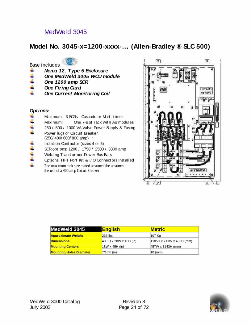
MedWeld 3045 Model No. 3045-x=1200-xxxx-…. (Allen-Bradley ® SLC 500)
Base includes Nema 12, Type 5 Enclosure One MedWeld 3005 WCU module One 1200 amp SCR One Firing Card One Current Monitoring Coil
Options:
Maximum: 3 SCRs – Cascade or Multi-timer Maximum: One 7-slot rack with AB modules 250 / 500 / 1000 VA Valve Power Supply & Fusing Power lugs or Circuit Breaker
(250/400/600/800 amp) * Isolation Contactor (sizes 4 or 5) SCR options: 1200 / 1750 / 2500 / 3300 amp Welding Transformer Power Bus Bars Options: HHT Port Kit & I/O Connectors Installed The maximum rack size stated assumes the assumes
the use of a 400 amp Circuit Breaker
MedWeld 3045 English Metric Approximate Weight 235 lbs 107 Kg
Dimensions 43.5H x 28W x 16D (in) 1105H x 711W x 406D (mm)
Mounting Centers 18W x 45H (in) 457W x 1143H (mm)
Mounting Holes Diameter 7/16th (in) 10 (mm)
MedWeld 3000 Catalog Revision 8 July 2002 Page 25 of 72
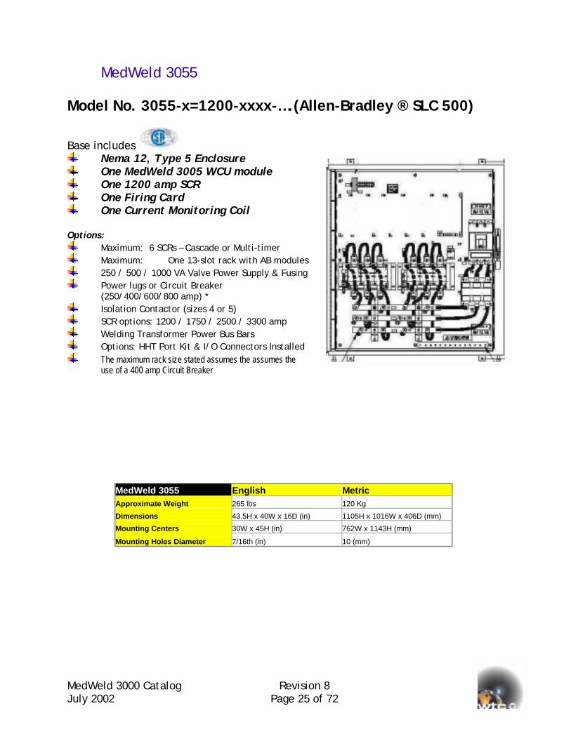
MedWeld 3055 Model No. 3055-x=1200-xxxx-….(Allen-Bradley ® SLC 500)
Base includes Nema 12, Type 5 Enclosure One MedWeld 3005 WCU module One 1200 amp SCR One Firing Card One Current Monitoring Coil
Options:
Maximum: 6 SCRs – Cascade or Multi-timer Maximum: One 13-slot rack with AB modules 250 / 500 / 1000 VA Valve Power Supply & Fusing Power lugs or Circuit Breaker
(250/400/600/800 amp) * Isolation Contactor (sizes 4 or 5) SCR options: 1200 / 1750 / 2500 / 3300 amp Welding Transformer Power Bus Bars Options: HHT Port Kit & I/O Connectors Installed The maximum rack size stated assumes the assumes the
use of a 400 amp Circuit Breaker
MedWeld 3055 English Metric Approximate Weight 265 lbs 120 Kg
Dimensions 43.5H x 40W x 16D (in) 1105H x 1016W x 406D (mm)
Mounting Centers 30W x 45H (in) 762W x 1143H (mm)
Mounting Holes Diameter 7/16th (in) 10 (mm)
MedWeld 3000 Catalog Revision 8 July 2002 Page 26 of 72
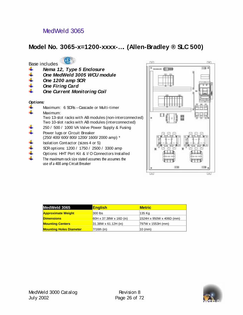
MedWeld 3065 Model No. 3065-x=1200-xxxx-…. (Allen-Bradley ® SLC 500)
Base includes Nema 12, Type 5 Enclosure One MedWeld 3005 WCU module One 1200 amp SCR One Firing Card One Current Monitoring Coil
Options:
Maximum: 6 SCRs – Cascade or Multi-timer Maximum:
Two 13-slot racks with AB modules (non-interconnected) Two 10-slot racks with AB modules (interconnected)
250 / 500 / 1000 VA Valve Power Supply & Fusing Power lugs or Circuit Breaker
(250/400/600/800/1200/1600/2000 amp) * Isolation Contactor (sizes 4 or 5) SCR options: 1200 / 1750 / 2500 / 3300 amp Options: HHT Port Kit & I/O Connectors Installed The maximum rack size stated assumes the assumes the
use of a 400 amp Circuit Breaker
MedWeld 3065 English Metric Approximate Weight 300 lbs 135 Kg
Dimensions 60H x 37.38W x 16D (in) 1524H x 950W x 406D (mm)
Mounting Centers 31.38W x 61.12H (in) 797W x 1553H (mm)
Mounting Holes Diameter 7/16th (in) 10 (mm)
MedWeld 3000 Catalog Revision 8 July 2002 Page 27 of 72
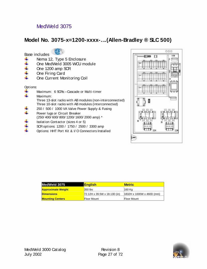
MedWeld 3075 Model No. 3075-x=1200-xxxx-….(Allen-Bradley ® SLC 500)
Base includes Nema 12, Type 5 Enclosure One MedWeld 3005 WCU module One 1200 amp SCR One Firing Card One Current Monitoring Coil
Options:
Maximum: 6 SCRs – Cascade or Multi-timer Maximum:
Three 13-slot racks with AB modules (non-interconnected) Three 10-slot racks with AB modules (interconnected)
250 / 500 / 1000 VA Valve Power Supply & Fusing Power lugs or Circuit Breaker
(250/400/600/800/1200/1600/2000 amp) * Isolation Contactor (sizes 4 or 5) SCR options: 1200 / 1750 / 2500 / 3300 amp Options: HHT Port Kit & I/O Connectors Installed
MedWeld 3075 English Metric Approximate Weight 350 lbs 160 Kg
Dimensions 72.12H x 39.5W x 18.13D (in) 1832H x 1000W x 460D (mm)
Mounting Centers Floor Mount Floor Mount
MedWeld 3000 Catalog Revision 8 July 2002 Page 28 of 72
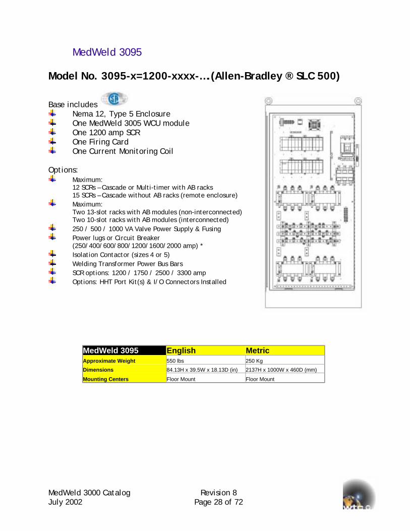
MedWeld 3095 Model No. 3095-x=1200-xxxx-….(Allen-Bradley ® SLC 500)
Base includes Nema 12, Type 5 Enclosure One MedWeld 3005 WCU module One 1200 amp SCR One Firing Card One Current Monitoring Coil
Options:
Maximum: 12 SCRs – Cascade or Multi-timer with AB racks 15 SCRs – Cascade without AB racks (remote enclosure)
Maximum: Two 13-slot racks with AB modules (non-interconnected) Two 10-slot racks with AB modules (interconnected)
250 / 500 / 1000 VA Valve Power Supply & Fusing Power lugs or Circuit Breaker
(250/400/600/800/1200/1600/2000 amp) * Isolation Contactor (sizes 4 or 5) Welding Transformer Power Bus Bars SCR options: 1200 / 1750 / 2500 / 3300 amp Options: HHT Port Kit(s) & I/O Connectors Installed
MedWeld 3095 English Metric Approximate Weight 550 lbs 250 Kg
Dimensions 84.13H x 39.5W x 18.13D (in) 2137H x 1000W x 460D (mm)
Mounting Centers Floor Mount Floor Mount
MedWeld 3000 Catalog Revision 8 July 2002 Page 29 of 72
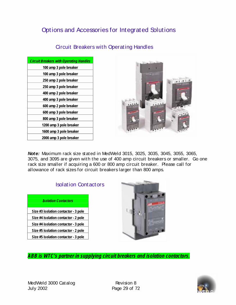
Options and Accessories for Integrated Solutions
Circuit Breakers with Operating Handles
Circuit Breakers with Operating Handles 100 amp 3 pole breaker 100 amp 3 pole breaker 250 amp 2 pole breaker 250 amp 3 pole breaker 400 amp 2 pole breaker 400 amp 3 pole breaker 600 amp 2 pole breaker 600 amp 3 pole breaker 800 amp 3 pole breaker
1200 amp 3 pole breaker 1600 amp 3 pole breaker 2000 amp 3 pole breaker
Note: Maximum rack size stated in MedWeld 3015, 3025, 3035, 3045, 3055, 3065, 3075, and 3095 are given with the use of 400 amp circuit breakers or smaller. Go one rack size smaller if acquiring a 600 or 800 amp circuit breaker. Please call for allowance of rack sizes for circuit breakers larger than 800 amps.
Isolation Contactors
Isolation Contactors
Size #3 isolation contactor - 3 pole Size #4 isolation contactor - 2 pole Size #4 isolation contactor - 3 pole Size #5 isolation contactor - 2 pole Size #5 isolation contactor - 3 pole
ABB is WTC’s partner in supplying circuit breakers and isolation contactors.

MedWeld 3000 Catalog Revision 8 July 2002 Page 30 of 72
SCR Upgrades
Additional MedWeld 3005 Controls & SCRs Additional MedWeld 3005 module & 1200 amp SCR
Additional 1200 amp SCR cascade
Upgrade to 1750 amp SCR from 1200 amp (per SCR)
Upgrade to 2500 amp SCR from 1200 amp (per SCR)
Upgrade to 3300 amp SCR from 1200 amp (per SCR)
Power Transformers
Power Transformers (120V: 220/480/600V) & Fusing 250 VA
500 VA
1000 VA
1500VA
2000 VA
3000 VA
5000 VA
Special Multitap Power Transformers
Power Transformers 14Pri Taps/10Sec Taps & Fusing
500 VA
3000 VA
600/575/550/500/480/460/440/416/400/380/240/230/220/208 V
130/125/120/115/110/100/99/95/91/85 V
DC Power Supplies
24 VDC Fused Power Supplies
1.2A @24Vdc (303-0407)
2.4A @ 24Vdc (303-0624)
16.7A @ 24Vdc (303-0608F)
250 VA Transformer
MedWeld 3000 Catalog Revision 8 July 2002 Page 31 of 72
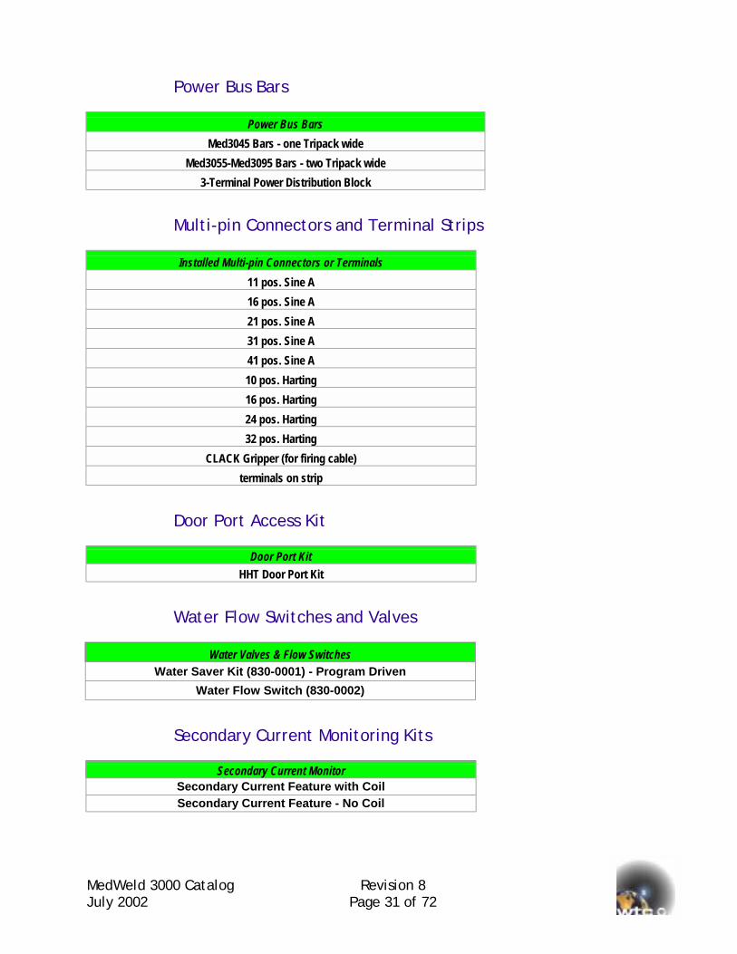
Power Bus Bars
Power Bus Bars Med3045 Bars - one Tripack wide
Med3055-Med3095 Bars - two Tripack wide 3-Terminal Power Distribution Block
Multi-pin Connectors and Terminal Strips
Installed Multi-pin Connectors or Terminals 11 pos. Sine A 16 pos. Sine A 21 pos. Sine A 31 pos. Sine A 41 pos. Sine A 10 pos. Harting 16 pos. Harting 24 pos. Harting 32 pos. Harting
CLACK Gripper (for firing cable) terminals on strip
Door Port Access Kit
Door Port Kit HHT Door Port Kit
Water Flow Switches and Valves
Water Valves & Flow Switches Water Saver Kit (830-0001) - Program Driven
Water Flow Switch (830-0002)
Secondary Current Monitoring Kits
Secondary Current Monitor Secondary Current Feature with Coil Secondary Current Feature - No Coil
MedWeld 3000 Catalog Revision 8 July 2002 Page 32 of 72
Allen-Bradley TM Components Please refer to Allen-Bradley TM Publication: 1746-PL001D-EN-P -November 2001 for description and specifications of these versatile products. Please reference descriptions below as a guide sheet for most common parts used in the MedWeld 3005 Integrated System. These prices are subject to change since Rockwell Automation controls them.
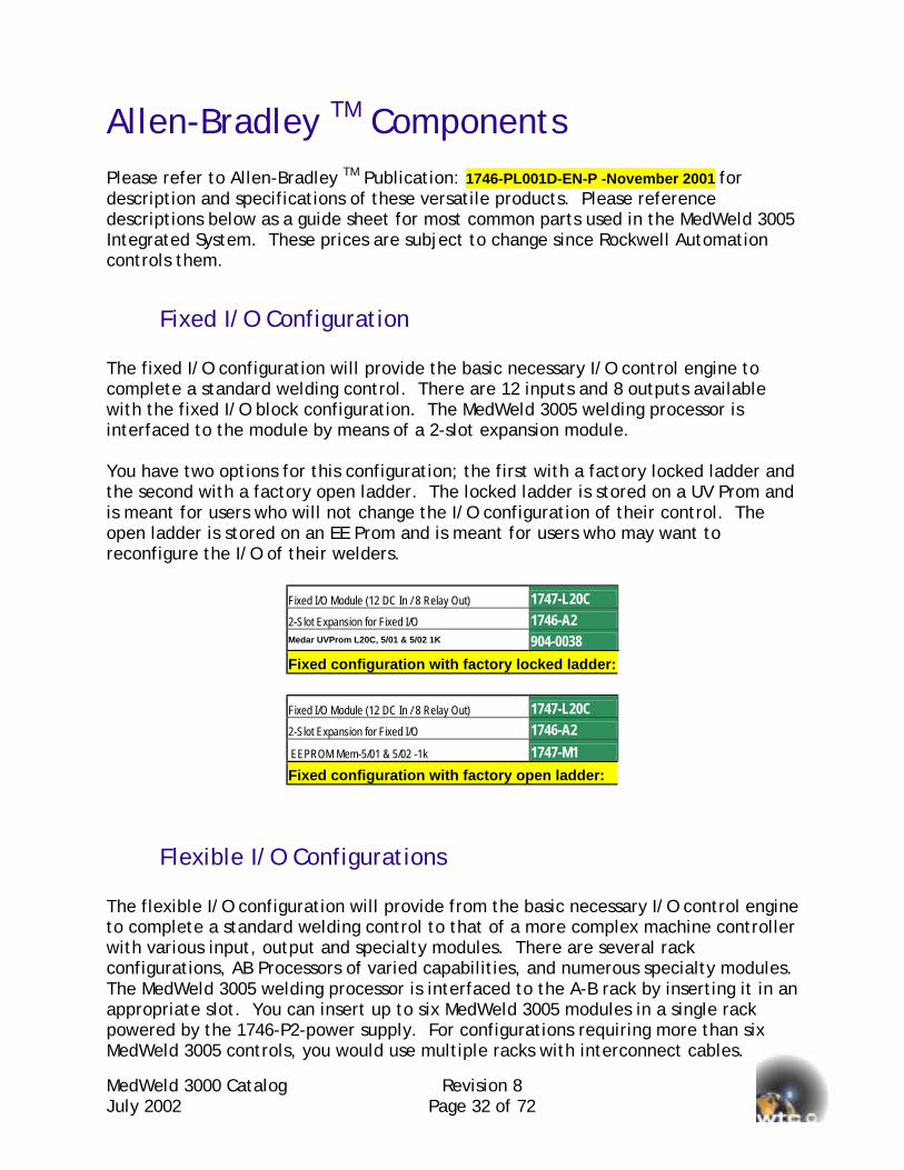
Fixed I/O Configuration The fixed I/O configuration will provide the basic necessary I/O control engine to complete a standard welding control. There are 12 inputs and 8 outputs available with the fixed I/O block configuration. The MedWeld 3005 welding processor is interfaced to the module by means of a 2-slot expansion module. You have two options for this configuration; the first with a factory locked ladder and the second with a factory open ladder. The locked ladder is stored on a UV Prom and is meant for users who will not change the I/O configuration of their control. The open ladder is stored on an EE Prom and is meant for users who may want to reconfigure the I/O of their welders.
Fixed I/O Module (12 DC In / 8 Relay Out) 1747-L20C 2-Slot Expansion for Fixed I/O 1746-A2 Medar UVProm L20C, 5/01 & 5/02 1K 904-0038 Fixed configuration with factory locked ladder:
Fixed I/O Module (12 DC In / 8 Relay Out) 1747-L20C 2-Slot Expansion for Fixed I/O 1746-A2 EEPROM Mem-5/01 & 5/02 -1k 1747-M1 Fixed configuration with factory open ladder:
Flexible I/O Configurations The flexible I/O configuration will provide from the basic necessary I/O control engine to complete a standard welding control to that of a more complex machine controller with various input, output and specialty modules. There are several rack configurations, AB Processors of varied capabilities, and numerous specialty modules. The MedWeld 3005 welding processor is interfaced to the A-B rack by inserting it in an appropriate slot. You can insert up to six MedWeld 3005 modules in a single rack powered by the 1746-P2-power supply. For configurations requiring more than six MedWeld 3005 controls, you would use multiple racks with interconnect cables.
MedWeld 3000 Catalog Revision 8 July 2002 Page 33 of 72
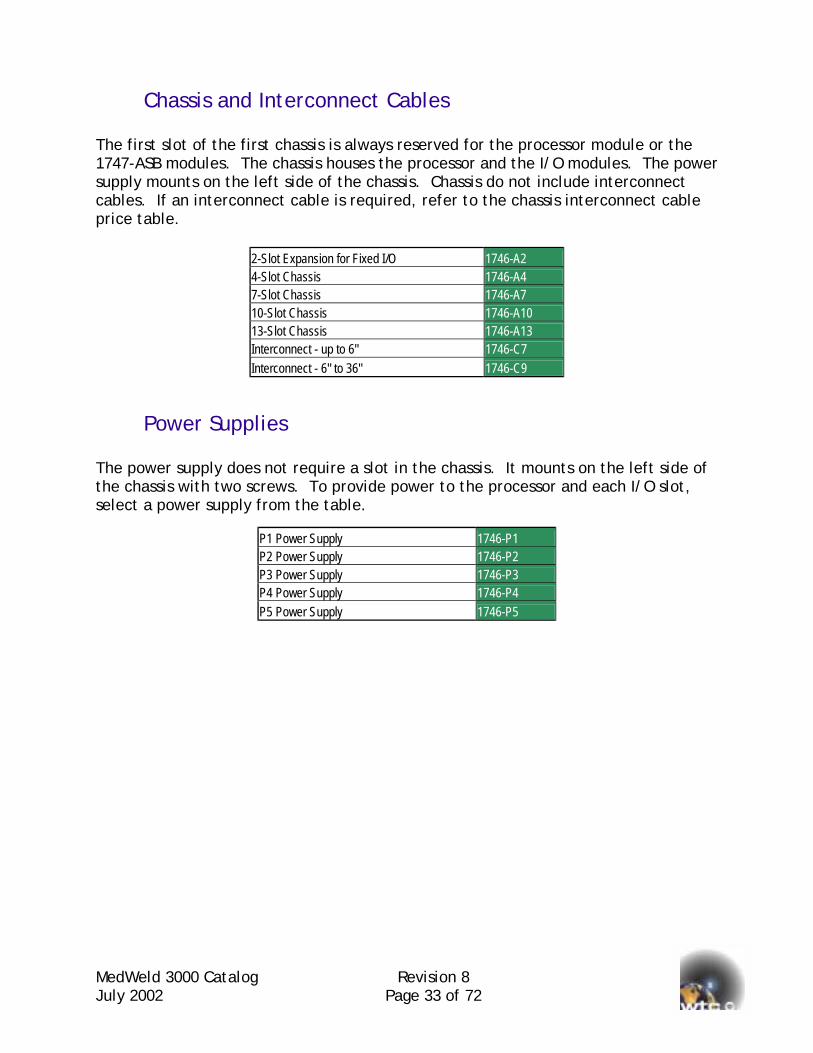
Chassis and Interconnect Cables The first slot of the first chassis is always reserved for the processor module or the 1747-ASB modules. The chassis houses the processor and the I/O modules. The power supply mounts on the left side of the chassis. Chassis do not include interconnect cables. If an interconnect cable is required, refer to the chassis interconnect cable price table.
2-Slot Expansion for Fixed I/O 1746-A2 4-Slot Chassis 1746-A4 7-Slot Chassis 1746-A7 10-Slot Chassis 1746-A10 13-Slot Chassis 1746-A13 Interconnect - up to 6" 1746-C7 Interconnect - 6" to 36" 1746-C9
Power Supplies The power supply does not require a slot in the chassis. It mounts on the left side of the chassis with two screws. To provide power to the processor and each I/O slot, select a power supply from the table.
P1 Power Supply 1746-P1 P2 Power Supply 1746-P2 P3 Power Supply 1746-P3 P4 Power Supply 1746-P4 P5 Power Supply 1746-P5
MedWeld 3000 Catalog Revision 8 July 2002 Page 34 of 72
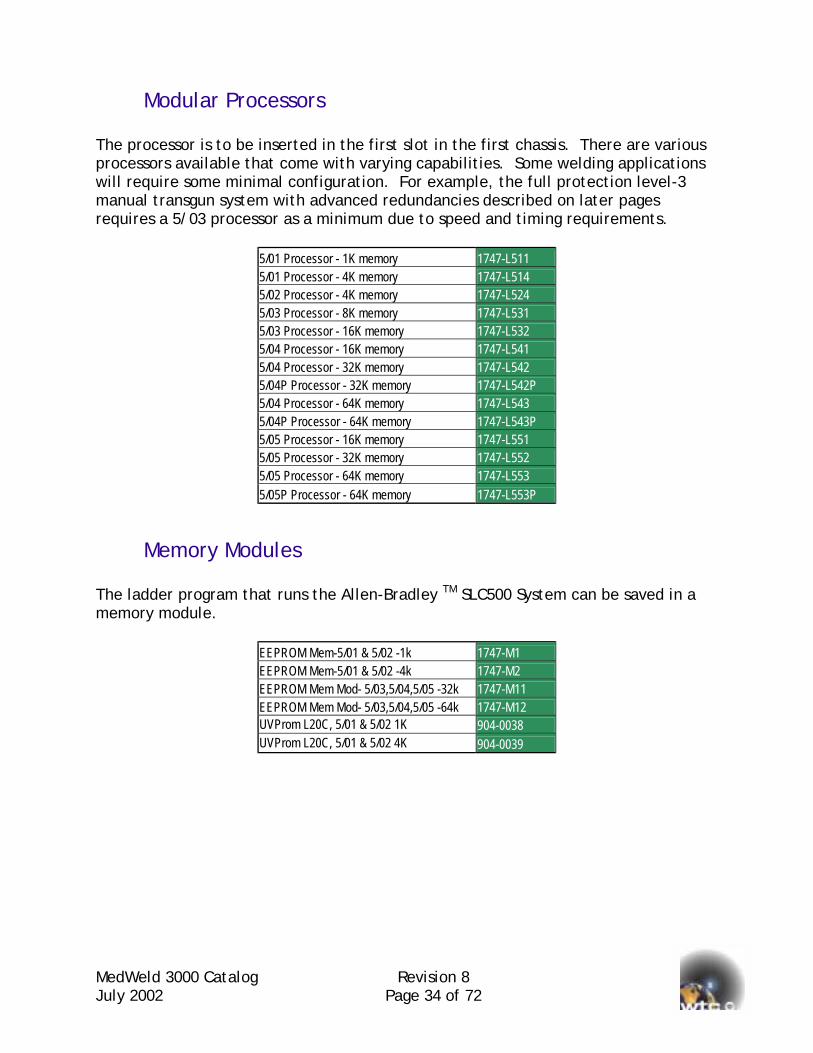
Modular Processors The processor is to be inserted in the first slot in the first chassis. There are various processors available that come with varying capabilities. Some welding applications will require some minimal configuration. For example, the full protection level-3 manual transgun system with advanced redundancies described on later pages requires a 5/03 processor as a minimum due to speed and timing requirements.
5/01 Processor - 1K memory 1747-L511 5/01 Processor - 4K memory 1747-L514 5/02 Processor - 4K memory 1747-L524 5/03 Processor - 8K memory 1747-L531 5/03 Processor - 16K memory 1747-L532 5/04 Processor - 16K memory 1747-L541 5/04 Processor - 32K memory 1747-L542 5/04P Processor - 32K memory 1747-L542P 5/04 Processor - 64K memory 1747-L543 5/04P Processor - 64K memory 1747-L543P 5/05 Processor - 16K memory 1747-L551 5/05 Processor - 32K memory 1747-L552 5/05 Processor - 64K memory 1747-L553 5/05P Processor - 64K memory 1747-L553P
Memory Modules The ladder program that runs the Allen-Bradley TM SLC500 System can be saved in a memory module.
EEPROM Mem-5/01 & 5/02 -1k 1747-M1 EEPROM Mem-5/01 & 5/02 -4k 1747-M2 EEPROM Mem Mod- 5/03,5/04,5/05 -32k 1747-M11 EEPROM Mem Mod- 5/03,5/04,5/05 -64k 1747-M12 UVProm L20C, 5/01 & 5/02 1K 904-0038 UVProm L20C, 5/01 & 5/02 4K 904-0039

MedWeld 3000 Catalog Revision 8 July 2002 Page 35 of 72
Input and Output Modules A wide variety of discrete I/O modules are available. The table is a partial listing of the most popular modules that have been used for a MedWeld 3005 system. Please refer to the Allen-Bradley TM publication for detailed specifications of each module.
120Vac Input Module -4 1746-IA4 120Vac Input Module -8 1746-IA8 120Vac Input Module -16 1746-IA16 120/240Vac Output Module -8 1746-OA8 120/240Vac Output Module -16 1746-OA16 120/240Vac Output Module -16 1746-OAP12 Current Sink - 24Vdc Input -8 1746-IB8 Current Sink - 24Vdc Input -16 1746-IB16 Current Sink - 24Vdc Input -32 1746-IB32 Current Sourcing - 24Vdc Input -8 1746-IV8 Current Sourcing - 24Vdc Input -16 1746-IV16 Current Sourcing - 24Vdc Input -32 1746-IV32 Current Sourcing - 24Vdc Output -8 1746-OB8 Current Sourcing - 24Vdc Output -16 1746-OB16 Current Sourcing - 24Vdc Output -32 1746-OB32 Current Sinking - 24Vdc Output -8 1746-OV8 Current Sinking - 24Vdc Output -16 1746-OV16 Current Sinking - 24Vdc Output -32 1746-OV32 AC/DC Relay Output -4 1746-OW4 AC/DC Relay Output -8 1746-OW8 AC/DC Relay Output -16 1746-OW16 AC/DC Isolated Relay Output -8 1746-OX8 120Vac In ( 2 ) - AC/DC Relay Out ( 2 ) 1746-IO4 120Vac In ( 4 ) - AC/DC Relay Out ( 4 ) 1746-IO8 120Vac In ( 6 ) - AC/DC Relay Out ( 6 ) 1746-IO12 24 Vdc In ( 6 ) - AC/DC Relay Out ( 6 ) 1746-IO12DC
MedWeld 3000 Catalog Revision 8 July 2002 Page 36 of 72
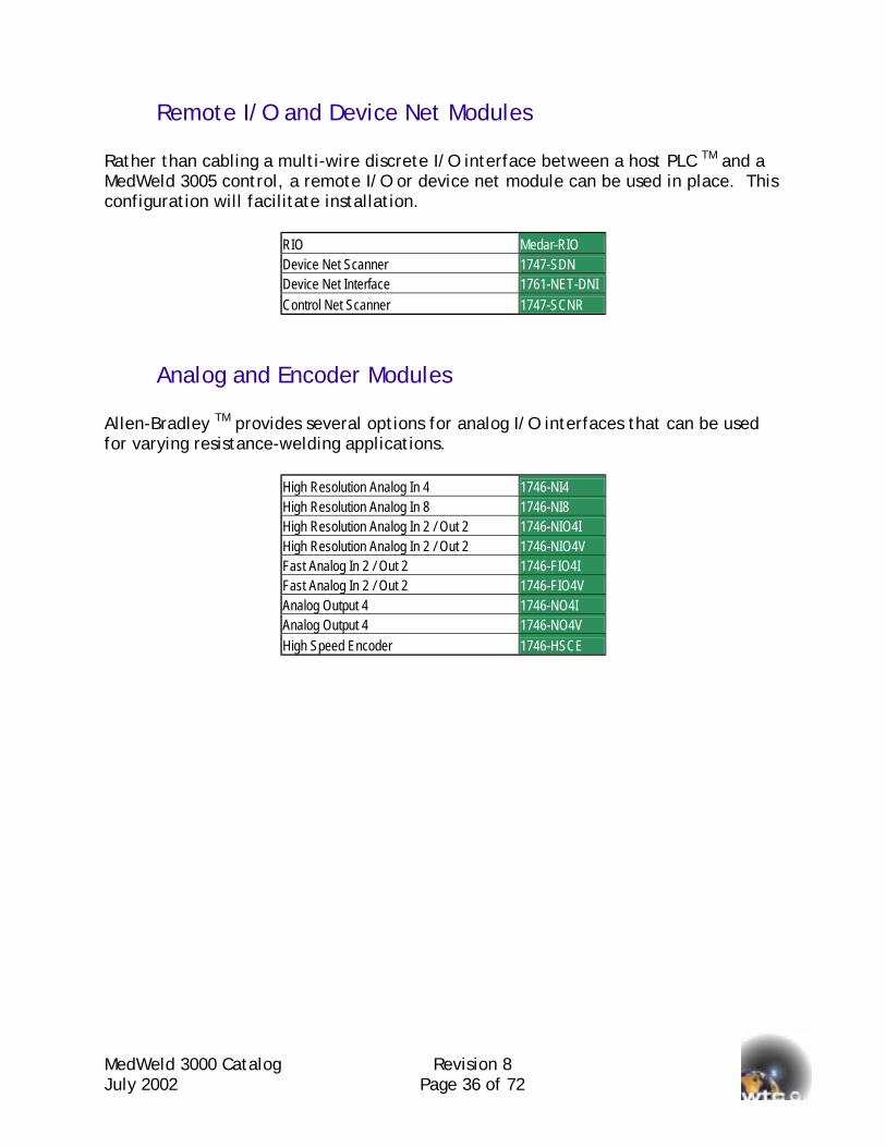
Remote I/O and Device Net Modules Rather than cabling a multi-wire discrete I/O interface between a host PLC TM and a MedWeld 3005 control, a remote I/O or device net module can be used in place. This configuration will facilitate installation.
RIO Medar-RIO Device Net Scanner 1747-SDN Device Net Interface 1761-NET-DNI Control Net Scanner 1747-SCNR
Analog and Encoder Modules Allen-Bradley TM provides several options for analog I/O interfaces that can be used for varying resistance-welding applications.
High Resolution Analog In 4 1746-NI4 High Resolution Analog In 8 1746-NI8 High Resolution Analog In 2 / Out 2 1746-NIO4I High Resolution Analog In 2 / Out 2 1746-NIO4V Fast Analog In 2 / Out 2 1746-FIO4I Fast Analog In 2 / Out 2 1746-FIO4V Analog Output 4 1746-NO4I Analog Output 4 1746-NO4V High Speed Encoder 1746-HSCE

MedWeld 3000 Catalog Revision 8 July 2002 Page 37 of 72
Cascade Weld Control Solutions The MedWeld 3005 Cascade system is available in kit, remote enclosures or fully integrated formats. In the remote enclosure format, a NEMA 12 enclosure is equipped with multiple 1200 amp SCRs, the cascade cards, one firing module, one current monitoring sensor, and the optional circuit breaker and isolation contactor. One MedWeld 3005 resistance-welding processor module is shipped with the enclosure to be installed in the main processor rack. There are four different remote enclosure models; MedWeld 3005 (2-SCRs), MedWeld 3045 (3-SCRs), MedWeld 3055 (6-SCRs) and MedWeld 3095 (12-SCRs with bus bars or 15 SCRs in a vertical stack-up). In the fully integrated scheme, a NEMA 12 enclosure is equipped with all the material of the remote enclosure system described above. It also accommodates the Allen-Bradley TM SLC 500 hardware for full machine and welding control requirements. A function in the MedWeld 3005 resistance-welding processor “TURN ON CONTACTOR SELECT #nn” is used for selecting the proper SCR to fire. The value “nn” is programmable from 01 to 15. The output for the contactor select can either be 24VAC, 24VDC or 120VAC. The cascade card automatically detects the voltage of the output point. Each cascade card can interface with 3 SCRs. Up to 5 cascade cards can be daisy-chained together for the selection of up to 15 SCRs. There is on-board hardware protection that ensures that only 1 SCR is selected even if more than one output is turned on. There are diagnostic LEDs to visually signify which SCR is addressed.
MeJu
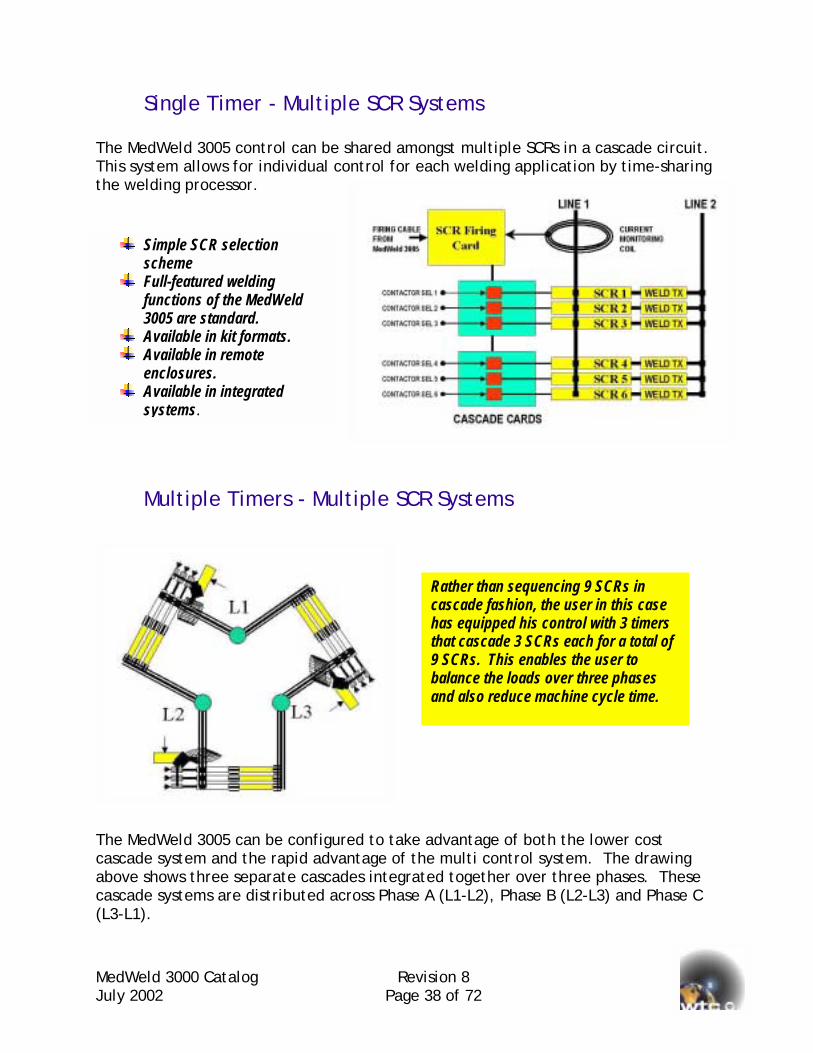
Single Timer - Multiple SCR Systems The MedWeld 3005 control can be shared amongst multiple SCRs in a cascade circuit. This system allows for individual control for each welding application by time-sharing the welding processor.
Thcaabca(L3
Simple SCR selection scheme
Full-featured welding functions of the MedWeld3005 are standard.
Available in kit formats. Available in remote
enclosures. Available in integrated
systems.
dWeld 3000 Catalog ly 2002
Multiple Timers - Mult
e MedWeld 3005 can be configurescade system and the rapid advanove shows three separate cascadscade systems are distributed acr-L1).
Revision 8 Page 38 of 72
iple SCR Systems
d to take advantage of both the lower cost tage of the multi control system. The drawing
es integrated together over three phases. These oss Phase A (L1-L2), Phase B (L2-L3) and Phase C
Rather than sequencing 9 SCRs in cascade fashion, the user in this case has equipped his control with 3 timers that cascade 3 SCRs each for a total of 9 SCRs. This enables the user to balance the loads over three phases and also reduce machine cycle time.

MedWeld 3000 Catalog Revision 8 July 2002 Page 39 of 72
Model Number Review for Cascade Systems The model of the above configuration can be as follows:
3095-3W9C=1200-xxxx-….. This means that this cascade system has 3 resistance-welding processor modules (-3W) and 9 SCRs in total (9C=1200). Part numbers are used to classify a product in a detailed manner. There are distinct bills of materials that are associated to a part number hence if you want to reorder an identical system to one that has been purchased before; you would specify a “Part Number”. Model numbers are descriptive numbers of a general nature. It is used to classify a product at a glance. Let’s discuss the differences between Integrated Multi Controls, Integrated Remote Single Phase Cascade, and Integrated Multi Controls with Cascade. Integrated Multi Control: 3075-6=1200-4003-1=#5-4806 This is a multi welder equipped with 6 resistance-welding modules, 6 SCRs (1200 amps), a 400 amp 3 pole breaker, and a size #5 isolation contactor wired for 480 volts 60 Hz. 3-phase Integrated or Remote Single Phase Cascade: 3055-6C=1200-4002-1=#5-4806 This can be a remote enclosure equipped with one resistance-welding module (shipped loose for installation in AB rack), or an integrated system that has one resistance-welding module in a rack within the enclosure. There are also 6 SCRs (1200 amps), a 400 amp 2-pole breaker, and a size #5 isolation contactor wired for 480 volts 60 Hz. Single phase. Integrated Multi Control with Cascade: 3075-3W6C=1200-4003-1=#5-4806 This is a multi welder equipped with 3 resistance-welding modules, 6 SCRs (1200 amps), a 400 amp 3-pole breaker, a size #5 isolation contactor wired for 480 volts 60 Hz. 3-phase.
MedWeld 3000 Catalog RevJuly 2002 Page
Mid-Frequency to DC (MFDC) Weld Control Solutions
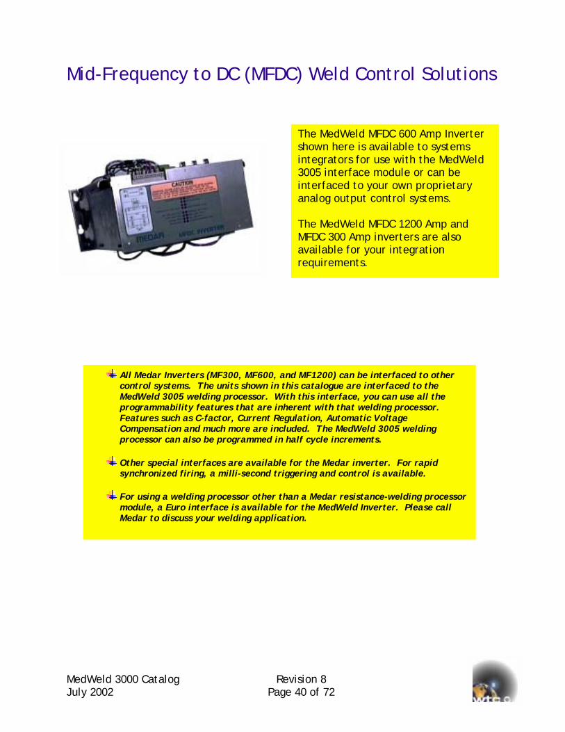
The MedWeld MFDC 600 Amp Invertershown here is available to systems integrators for use with the MedWeld 3005 interface module or can be interfaced to your own proprietary analog output control systems. The MedWeld MFDC 1200 Amp and MFDC 300 Amp inverters are also available for your integration requirements.
All Medar Inverters (MF300, MF600, and MF1200) can be interfaced to other control systems. The units shown in this catalogue are interfaced to the MedWeld 3005 welding processor. With this interface, you can use all the programmability features that are inherent with that welding processor. Features such as C-factor, Current Regulation, Automatic Voltage Compensation and much more are included. The MedWeld 3005 welding processor can also be programmed in half cycle increments.
Other special interfaces are available for the Medar inverter. For rapid synchronized firing, a milli-second triggering and control is available.
For using a welding processor other than a Medar resistance-welding processor module, a Euro interface is available for the MedWeld Inverter. Please call Medar to discuss your welding application.
ision 8 40 of 72

MedWeld 3000 Catalog Revision 8 July 2002 Page 41 of 72
Benefits of MFDC Welding Systems There are applications and situations where the MFDC resistance welding is the best choice available. Although there are significantly higher initial prices, the overall cost of using MFDC over single and three-phase SCR control may actually be significantly lower. Consider these advantages:
Significant Energy Savings: - for plants that cannot purchase more electrical power, the MFDC approach may allow you to do more projects with less energy.
Improved and Consistent Power Factor: - the MFDC load appears to have unity power factor, which would then reduce penalties assessed by the power company.
Automatic Load Distribution: - the MFDC load is evenly distributed across all three phases. The bank of capacitors that are found on the MFDC system allows for current to draw from the bank as well as from the line thus reducing peak line currents.
Welding is Tolerant of Electrical Line Disturbances: - the energy reserve of the capacitor banks will smooth out line notches and line spikes even while welding is taking place.
Eliminates Need and Maintenance of Expensive Kickless Cables: - because of the higher operating frequencies (400 to 1600Hz), the welding transformer can be as much as 74% smaller than the traditional line frequency (50 / 60 Hz). This allows the user to locate the transformer much closer to the welding gun thus eliminating the use of expensive Kickless cables that need to be maintained and monitored.
Precise Welding Current Control: - the MFDC utilizes IGBTs for switching. These are turned on and off at the rate of 400 to 2000 times per second. By controlling both the turn on and turn off, the MFDC can determine the current to control. Conventional controls utilize SCRs for switching. These are turned on by the weld control but then remain conducting until the line voltage crosses the zero point during the base frequency line cycle. Because of this, conventional controls must use a predictive algorithm rather than a deterministic approach. Also, if an under or over compensation occurs on one of the cycles, the conventional will have to wait until the next period of the base frequency whereas the MFDC need only wait a fraction (1/20th nominal) of that time.
Attains Target Current Immediately: - DC systems of the SCR type have a rise time prior to its steady state. Since the MFDC is so responsive, it is possible to create full phase firing during the natural rise time to lessen that period of time.
More Process Friendly: - the MFDC eliminates undesired inter-cycle cooling periods that exist in AC resistance welding processes. Welding therefore can occur faster which would then reduce heat waste and the problems associated to eliminating that waste.
MedWeJuly 20
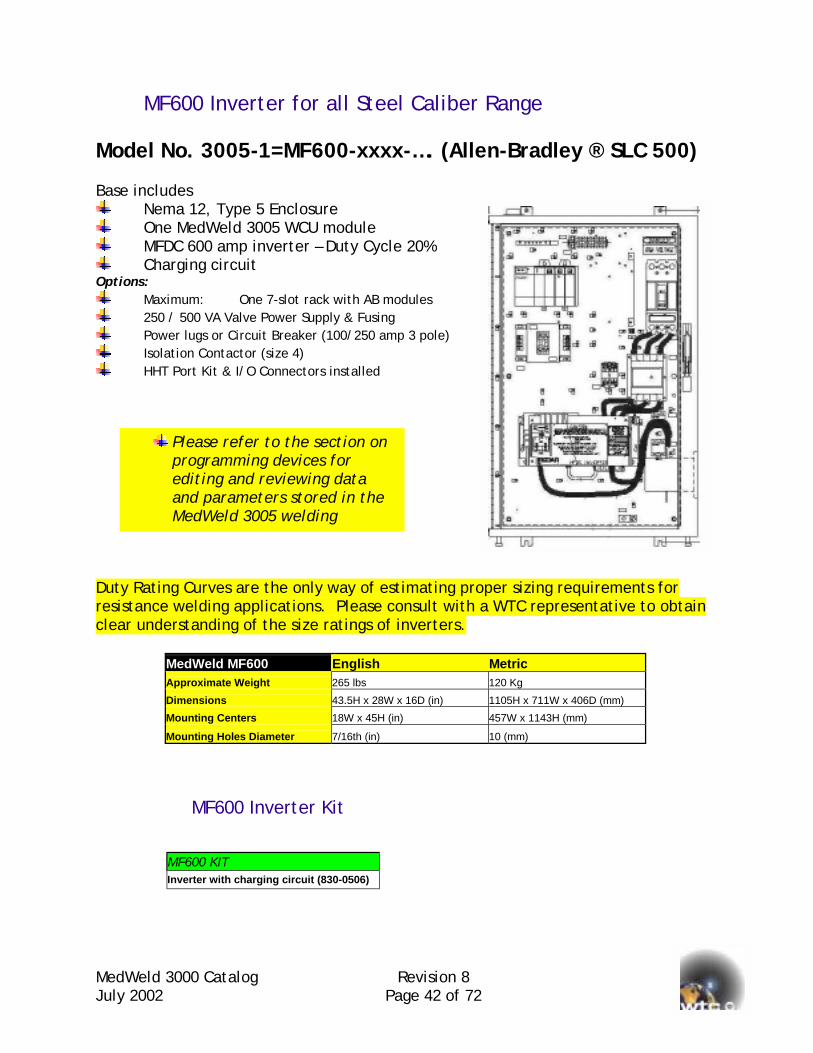
MF600 Inverter for all Steel Caliber Range Model No. 3005-1=MF600-xxxx-…. (Allen-Bradley ® SLC 500) Base includes
Nema 12, Type 5 Enclosure One MedWeld 3005 WCU module MFDC 600 amp inverter – Duty Cycle 20% Charging circuit
Options: Maximum: One 7-slot rack with AB modules 250 / 500 VA Valve Power Supply & Fusing Power lugs or Circuit Breaker (100/250 amp 3 pole) Isolation Contactor (size 4) HHT Port Kit & I/O Connectors installed
Duty Raresistanclear u
Please refer to the section onprogramming devices for editing and reviewing data and parameters stored in the MedWeld 3005 welding
ld 3000 Catalog Revision 8 02 Page 42 of 72
ting Curves are the only way of estimating proper sizing requirements for ce welding applications. Please consult with a WTC representative to obtain
nderstanding of the size ratings of inverters.
MedWeld MF600 English Metric Approximate Weight 265 lbs 120 Kg
Dimensions 43.5H x 28W x 16D (in) 1105H x 711W x 406D (mm)
Mounting Centers 18W x 45H (in) 457W x 1143H (mm)
Mounting Holes Diameter 7/16th (in) 10 (mm)
MF600 Inverter Kit
MF600 KIT Inverter with charging circuit (830-0506)
MedWeld 3000 Catalog Revision 8 July 2002 Page 43 of 72
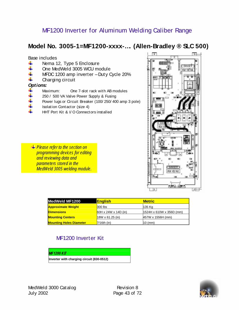
MF1200 Inverter for Aluminum Welding Caliber Range Model No. 3005-1=MF1200-xxxx-…. (Allen-Bradley ® SLC 500) Base includes
Nema 12, Type 5 Enclosure One MedWeld 3005 WCU module MFDC 1200 amp inverter – Duty Cycle 20% Charging circuit
Options: Maximum: One 7-slot rack with AB modules 250 / 500 VA Valve Power Supply & Fusing Power lugs or Circuit Breaker (100/250/400 amp 3 pole) Isolation Contactor (size 4) HHT Port Kit & I/O Connectors installed
MedWeld MF1200 English Metric Approximate Weight 300 lbs 135 Kg
Dimensions 60H x 24W x 14D (in) 1524H x 610W x 356D (mm)
Mounting Centers 18W x 61.25 (in) 457W x 1556H (mm)
Mounting Holes Diameter 7/16th (in) 10 (mm)
MF1200 Inverter Kit
MF1200 KIT Inverter with charging circuit (830-0512)
Please refer to the section on programming devices for editing and reviewing data and parameters stored in the MedWeld 3005 welding module.
MedWeld 3000 Catalog Revision 8 July 2002 Page 44 of 72
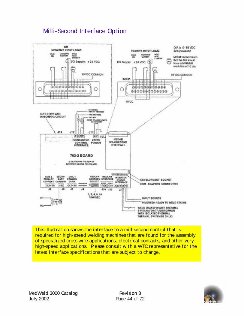
Milli-Second Interface Option
This illustration shows the interface to a millisecond control that is required for high-speed welding machines that are found for the assembly of specialized cross wire applications, electrical contacts, and other very high-speed applications. Please consult with a WTC representative for the latest interface specifications that are subject to change.
MedWeld 3000 Catalog July 2002
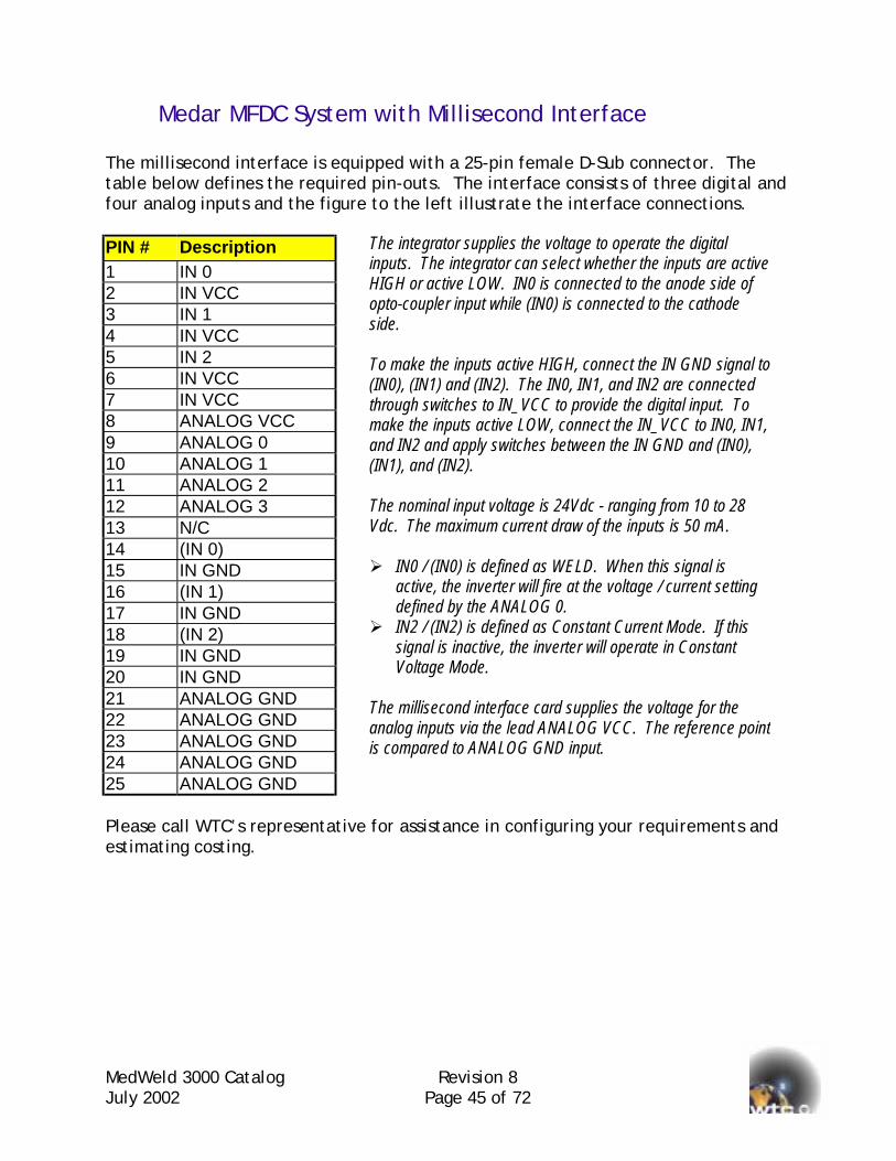
Medar MFDC System with Millisecond Interface The millisecond interface is equipped with a 25-pin female D-Sub connector. The table below defines the required pin-outs. The interface consists of three digital and four analog inputs and the figure to the left illustrate the interface connections. PIN # Description 1 IN 0 2 IN VCC 3 IN 1 4 IN VCC 5 IN 2 6 IN VCC 7 IN VCC 8 ANALOG VCC 9 ANALOG 0 10 ANALOG 1 11 ANALOG 2 12 ANALOG 3 13 N/C 14 (IN 0) 15 IN GND 16 (IN 1) 17 IN GND 18 (IN 2) 19 IN GND 20 IN GND 21 ANALOG GND 22 ANALOG GND 23 ANALOG GND 24 ANALOG GND 25 ANALOG GND Please call WTC’s representativeestimating costing.
The integrator supplies the voltage to operate the digital inputs. The integrator can select whether the inputs are active HIGH or active LOW. IN0 is connected to the anode side of opto-coupler input while (IN0) is connected to the cathode side. To make the inputs active HIGH, connect the IN GND signal to(IN0), (IN1) and (IN2). The IN0, IN1, and IN2 are connected through switches to IN_VCC to provide the digital input. To make the inputs active LOW, connect the IN_VCC to IN0, IN1, and IN2 and apply switches between the IN GND and (IN0), (IN1), and (IN2). The nominal input voltage is 24Vdc - ranging from 10 to 28 Vdc. The maximum current draw of the inputs is 50 mA. ! IN0 / (IN0) is defined as WELD. When this signal is
active, the inverter will fire at the voltage / current setting defined by the ANALOG 0.
! IN2 / (IN2) is defined as Constant Current Mode. If this signal is inactive, the inverter will operate in Constant Voltage Mode.
The millisecond interface card supplies the voltage for the analog inputs via the lead ANALOG VCC. The reference pointis compared to ANALOG GND input.
Revision 8 Page 45 of 72
for assistance in configuring your requirements and

MedWeld 3000 Catalog Revision 8 July 2002 Page 46 of 72
MedWeld 3005 3-Phase to DC Weld Controls
Single MedWeld 3-Phase System
The MedWeld 3005 can be configured for Three-Phase to DC applications. The flexibility of the Allen-Bradley SLC 500 system permits some unique and innovative solutions for welding. Analog interface solutions are readily available. Even more unique is the possibility of configuring cascade three phase systems.
WTP – Single MedWeld Three-Phase The MedWeld processor resides in the Allen-Bradley SLC 500 rack. It is interfaced to three sets of inversed parallel SCRs for controlling three phases to DC welding transformer. A single MedWeld 3005 weld processor utilizes a firing board multiplexer to sequence the firing of the SCRs in proper rotation and order. “W” signifies that there will be one MedWeld module. “TP” signifies that there will be one Three-Phase assembly that comprises of one FBM, three firing cards, three SCRs, and three current monitoring coils. WTP=2500 means that the SCRs are rated at 2500 amperes – 50% duty cycle.
MedWeld 3000 Catalog Revision 8 July 2002 Page 47 of 72
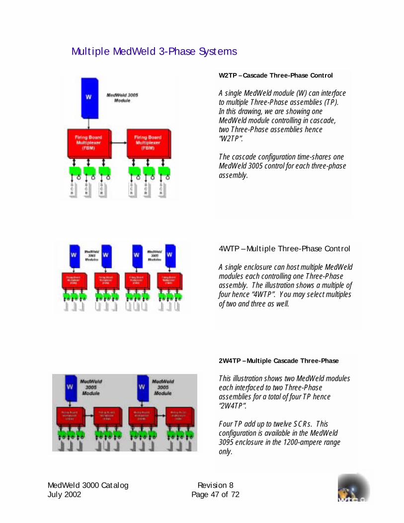
Multiple MedWeld 3-Phase Systems
W2TP – Cascade Three-Phase Control A single MedWeld module (W) can interface to multiple Three-Phase assemblies (TP). In this drawing, we are showing one MedWeld module controlling in cascade, two Three-Phase assemblies hence “W2TP”. The cascade configuration time-shares one MedWeld 3005 control for each three-phase assembly.
4WTP – Multiple Three-Phase Control A single enclosure can host multiple MedWeld modules each controlling one Three-Phase assembly. The illustration shows a multiple of four hence “4WTP”. You may select multiples of two and three as well.
2W4TP – Multiple Cascade Three-Phase This illustration shows two MedWeld modules each interfaced to two Three-Phase assemblies for a total of four TP hence “2W4TP”. Four TP add up to twelve SCRs. This configuration is available in the MedWeld 3095 enclosure in the 1200-ampere range only.

MedJuly
Model Numbers for 3-Phase Systems
MedWeld 3005 Three Phase to DC MedWeld 3035 -WTP=1200 MedWeld 3035 -WTP=1750 MedWeld 3035 -WTP=2500 MedWeld 3035 -WTP=3300 MedWeld 3065 -WTP=1200 MedWeld 3065 -WTP=1750 MedWeld 3065 -WTP=2500 MedWeld 3065 -WTP=3300 MedWeld 3075 -WTP=1200 MedWeld 3075 -WTP=1750 MedWeld 3075 -WTP=2500 MedWeld 3075 -WTP=3300 MedWeld 3095 -WTP=1200 MedWeld 3095 -WTP=1750 MedWeld 3095 -WTP=2500 MedWeld 3095 -WTP=3300
Note on Current Monitoring for AC and 3-Phase to DC Controls: The current transformer coil shown above and throughout this catalog is used on AC and 3-Phase to DC controls. This device is suited for currents above 50 amperes. For applications below this level, please consult with WTC and request for the document entitled “Guidelines to Select a Sensor to Measure Welding Current”.
Additional Three Phase to DC additonal WTP=1200 additonal TP=1200
additonal WTP=1750 additonal TP=1750
additonal WTP=2500 additonal TP=2500
additonal WTP=3300 additonal TP=3300
Seam Welding with 3-Phase Welding Controls WTC welding controls provide a load resistor across the welding transformer. This resistor assures proper SCR firing and transient voltage suppression under all operating conditions. The load resistor supplied as standard equipment is designed for spot welding or short duration seam welding use with a maximum weld time of 5 seconds and a maximum duty cycle of 33%. If your welding application involves weld times longer than 5 seconds per weld or an overall duty cycle exceeding 33%, a larger load resistor is required. Please contact the factory or your sales representative to obtain the correct load resistor for your application.
Weld 3000 Catalog Revision 8 2002 Page 48 of 72
MedWeld 3000 Catalog Revision 8 July 2002 Page 49 of 72
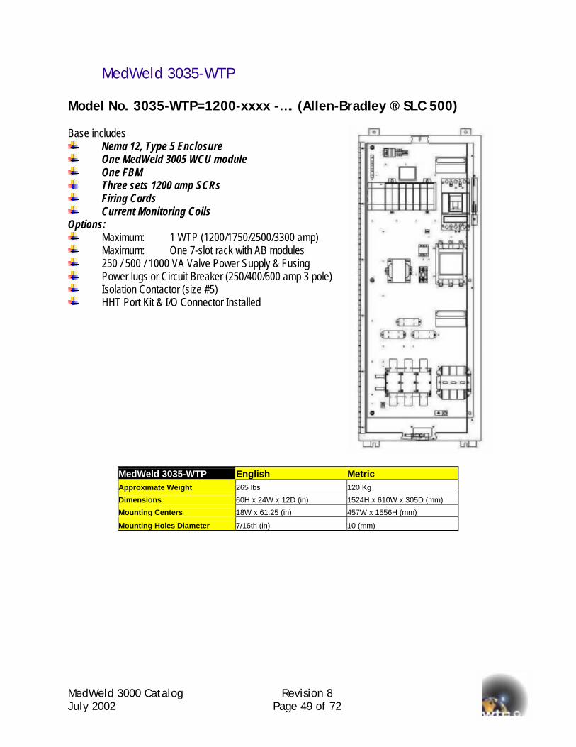
MedWeld 3035-WTP Model No. 3035-WTP=1200-xxxx -…. (Allen-Bradley ® SLC 500) Base includes
Nema 12, Type 5 Enclosure One MedWeld 3005 WCU module One FBM Three sets 1200 amp SCRs Firing Cards Current Monitoring Coils
Options: Maximum: 1 WTP (1200/1750/2500/3300 amp) Maximum: One 7-slot rack with AB modules 250 / 500 / 1000 VA Valve Power Supply & Fusing Power lugs or Circuit Breaker (250/400/600 amp 3 pole) Isolation Contactor (size #5) HHT Port Kit & I/O Connector Installed
MedWeld 3035-WTP English Metric Approximate Weight 265 lbs 120 Kg
Dimensions 60H x 24W x 12D (in) 1524H x 610W x 305D (mm)
Mounting Centers 18W x 61.25 (in) 457W x 1556H (mm)
Mounting Holes Diameter 7/16th (in) 10 (mm)
MedWeld 3000 Catalog Revision 8 July 2002 Page 50 of 72
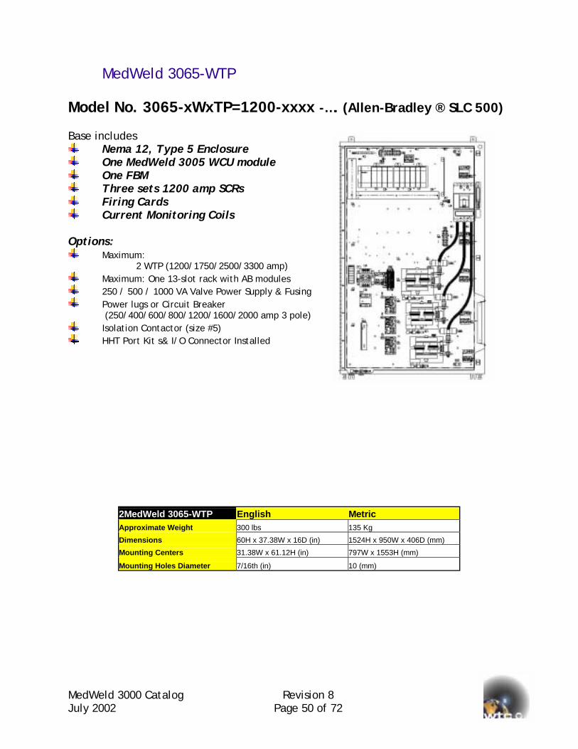
MedWeld 3065-WTP Model No. 3065-xWxTP=1200-xxxx -…. (Allen-Bradley ® SLC 500) Base includes
Nema 12, Type 5 Enclosure One MedWeld 3005 WCU module One FBM Three sets 1200 amp SCRs Firing Cards Current Monitoring Coils
Options:
Maximum: 2 WTP (1200/1750/2500/3300 amp)
Maximum: One 13-slot rack with AB modules 250 / 500 / 1000 VA Valve Power Supply & Fusing Power lugs or Circuit Breaker
(250/400/600/800/1200/1600/2000 amp 3 pole) Isolation Contactor (size #5) HHT Port Kit s& I/O Connector Installed
2MedWeld 3065-WTP English Metric Approximate Weight 300 lbs 135 Kg
Dimensions 60H x 37.38W x 16D (in) 1524H x 950W x 406D (mm)
Mounting Centers 31.38W x 61.12H (in) 797W x 1553H (mm)
Mounting Holes Diameter 7/16th (in) 10 (mm)
MedWeld 3000 Catalog Revision 8 July 2002 Page 51 of 72
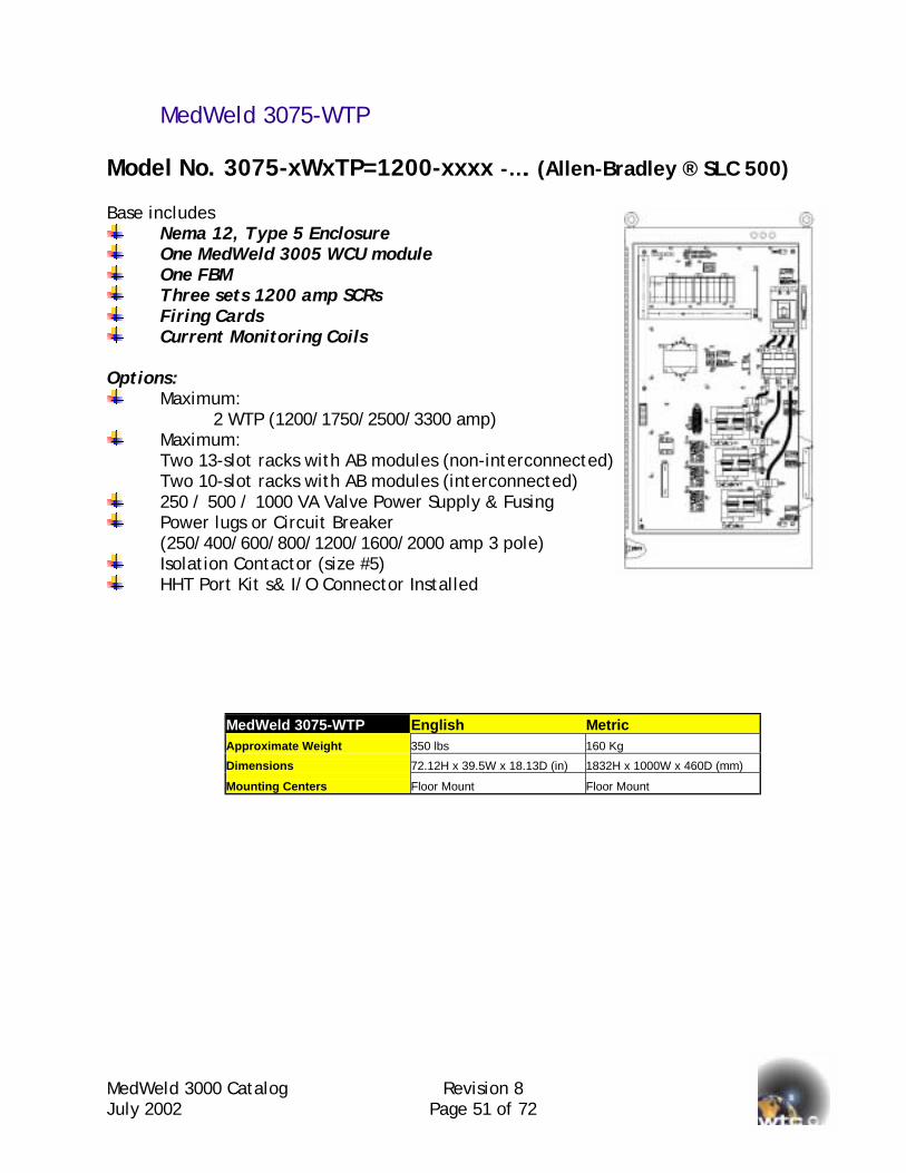
MedWeld 3075-WTP Model No. 3075-xWxTP=1200-xxxx -…. (Allen-Bradley ® SLC 500) Base includes
Nema 12, Type 5 Enclosure One MedWeld 3005 WCU module One FBM Three sets 1200 amp SCRs Firing Cards Current Monitoring Coils
Options:
Maximum: 2 WTP (1200/1750/2500/3300 amp)
Maximum: Two 13-slot racks with AB modules (non-interconnected) Two 10-slot racks with AB modules (interconnected)
250 / 500 / 1000 VA Valve Power Supply & Fusing Power lugs or Circuit Breaker
(250/400/600/800/1200/1600/2000 amp 3 pole) Isolation Contactor (size #5) HHT Port Kit s& I/O Connector Installed
MedWeld 3075-WTP English Metric
Approximate Weight 350 lbs 160 Kg
Dimensions 72.12H x 39.5W x 18.13D (in) 1832H x 1000W x 460D (mm)
Mounting Centers Floor Mount Floor Mount
MedWeld 3000 Catalog Revision 8 July 2002 Page 52 of 72
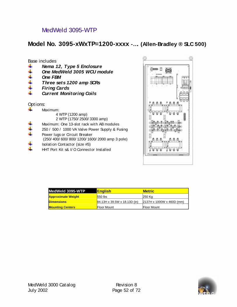
MedWeld 3095-WTP Model No. 3095-xWxTP=1200-xxxx -…. (Allen-Bradley ® SLC 500) Base includes
Nema 12, Type 5 Enclosure One MedWeld 3005 WCU module One FBM Three sets 1200 amp SCRs Firing Cards Current Monitoring Coils
Options:
Maximum: 4 WTP (1200 amp) 2 WTP (1750/2500/3300 amp)
Maximum: One 13-slot rack with AB modules 250 / 500 / 1000 VA Valve Power Supply & Fusing Power lugs or Circuit Breaker
(250/400/600/800/1200/1600/2000 amp 3 pole) Isolation Contactor (size #5) HHT Port Kit s& I/O Connector Installed
MedWeld 3095-WTP English Metric Approximate Weight 550 lbs 250 Kg
Dimensions 84.13H x 39.5W x 18.13D (in) 2137H x 1000W x 460D (mm)
Mounting Centers Floor Mount Floor Mount

MedWeld 3000 Catalog Revision 8 July 2002 Page 53 of 72
Model Number Review for 3-Phase Systems The model numbering scheme is the same for 3-Phase systems as they are for single-phase systems and cascades with the difference being that the second grouping of alpha-numeric characters calls out for “WTP” for “Welding Three Phase”.
3065-1W2TP=1750-xxxx-….. Part numbers are used to classify a product in a detailed manner. There are distinct bills of materials that are associated to a part number hence if you want to reorder an identical system to one that has been purchased before; you would specify a “Part Number”. Model numbers are descriptive numbers of a general nature. It is used to classify a product at a glance. The preceding pages describe how to group the WTPs together. Select appropriate WTP enclosure model (3035, 3065, 3075, or 3095). Additional number of MedWeld 3005 “WTP” resistance-welding processors. Additional number of “TP” power switches. Add options and accessories required. Add Allen-Bradley TM components required.

MedWeld 3000 Catalog Revision 8 July 2002 Page 54 of 72
Safety Ground Fault Systems for Manually Operated Transguns Monitoring and control circuits are required for ensuring the safety of human beings who operate a welding gun that is integrated with a welding transformer. There is high voltage cables that come in close proximity to the person who manipulates the “transgun” hence several designs need to be incorporated into the tool to make sure that the person does not become the easy path to ground for a primary electrical short circuits. At a minimum, the following three requirements must be included:
The integrity of the ground cable between the control and the welding transformer needs to be monitored at all times to assure that the cable would be capable of grounding out the primary short in the event of occurrence.
Imbalances of current between the control and transformer need to be monitored at all times. Should the current to the transformer exceed the current returning from the transformer by 10 mA or greater, it would be presumed that primary current is finding its way to ground. The control must then isolate the welding gun from the power lines.
A grounded metallic shield must surround the power cables between the welding transformer and the welding control. The shield is grounded in the control and not at the welding gun. There are additional monitoring and control functions that can be implemented to ensure safety. Some of these are listed as follows:
An isolation contactor can be included to remove the power line from the transformer during equipment idle time.
Periodic measuring and verification that the insulation covering the primary cables is adequate.
Automatic control testing and validation can be incorporated into the design to ensure that all the safety-monitoring circuits are functioning.

MedWeld 3000 Catalog Revision 8 July 2002 Page 55 of 72
2-Level Detection System The simpler design is available with the MedWeld 3005 control. This design incorporates the use an independent safety monitoring system to supervise the integrity of the ground cable and monitors for primary current imbalance. If a fault is detected, the safety system will isolate the welding gun from the power lines by tripping the circuit breaker. An under-voltage trip breaker is used for failsafe condition. The power to sustain the breaker operation must come from an external source or from the line side of the circuit breaker. When taking power from the line side of the breaker, the use of special “Touchsafe” fuse holders is required.
2-Level Manual Gun Safety Protection System Option Installed For use with the MedWeld 3005 Series Controls This includes a GFI monitor and a current imbalance-monitoring coil with push to test button & indicator.
“Touchsafe” Switch & Power Supply Installed This option is required for use with the manual gun safety system for under-voltage trip breaker if external power is not provided. The power is taken from the line side of the circuit breaker and can be disconnected safely. The power supply is to energize the GFI Monitor System and the UV mechanism of the circuit breaker.

MedWeld 3000 Catalog Revision 8 July 2002 Page 56 of 72
3-Level Detection System A more advanced safety design is available with the MedWeld 3005. This design incorporates the monitoring of the ground integrity, imbalance of current and also monitors the resistance of the insulation covering the primary cables to verify that it is greater than 250 K ohms to 2 M ohms. The verification of adequate primary insulation is accomplished with the use an independent monitoring system. This verification takes place during idle time where an isolation contactor removes the manual transformer-gun from the power lines. If the insulation resistance is too low, the control will generate a fault and prevent the isolation contactor from pulling in. This design uses the advanced programming capability of the Allen-Bradley TM 5/03 processor to build in a redundancy that assures full protection. On power-up and each time the welding control remains idle for more than 30 minutes, the system will automatically execute a verification test to ensure that the monitoring circuits are functioning. If the safety monitoring system does not detect the simulated faults, the Medar processor will generate a fault and prevent an unsafe condition from taking place. A standard shunt trip for the circuit breaker is used since the power to trip the breaker is also the power to pull in the isolation contactor.
3-level Manual Gun Safety Protection System Installed Minimal Requirements:
Circuit breaker with shunt trip Isolation contactor AB 5/03 – 8K processor (1747-L531) AB output card for shunt trip – OA or OB type

MedWeld 3000 Catalog Revision 8 July 2002 Page 57 of 72
Programming Devices for MedWeld Controls
DEP100s Part No. 937-0009 (as shown) 937-0009V2 (with mounting tabs for panel mount) Equipped with a 10ft (3.05 meter) cable Part No. 205-1086
User-friendly programming for MedWeld controls Graphical display for viewing data 5 x 6 matrix sealed keys with positive touch response Industrialized metal enclosure for plant environment Convenient metal handle for hanging on NPP bracket Address programming feature for network setup Insert / Delete function capability Review Welding / Fault Data for diagnostics Plugs into local port or network power pack
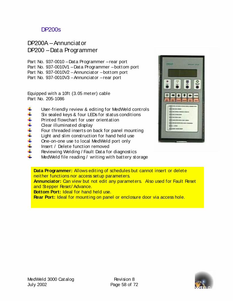
MedWeld 3000 Catalog Revision 8 July 2002 Page 58 of 72
DP200s DP200A – Annunciator DP200 – Data Programmer Part No. 937-0010 – Data Programmer – rear port Part No. 937-0010V1 – Data Programmer – bottom port Part No. 937-0010V2 – Annunciator – bottom port Part No. 937-0010V3 – Annunciator – rear port Equipped with a 10ft (3.05 meter) cable Part No. 205-1086
User-friendly review & editing for MedWeld controls Six sealed keys & four LEDs for status conditions Printed flowchart for user orientation Clear illuminated display Four threaded inserts on back for panel mounting Light and slim construction for hand held use One-on-one use to local MedWeld port only Insert / Delete function removed Reviewing Welding /Fault Data for diagnostics MedWeld file reading / writing with battery storage
Data Programmer: Allows editing of schedules but cannot neither functions nor access setup parameters. Annunciator: Can view but not edit any parameters. Also and Stepper Reset/Advance. Bottom Port: Ideal for hand held use. Rear Port: Ideal for mounting on panel or enclosure door v
insert or delete
used for Fault Reset
ia access hole.
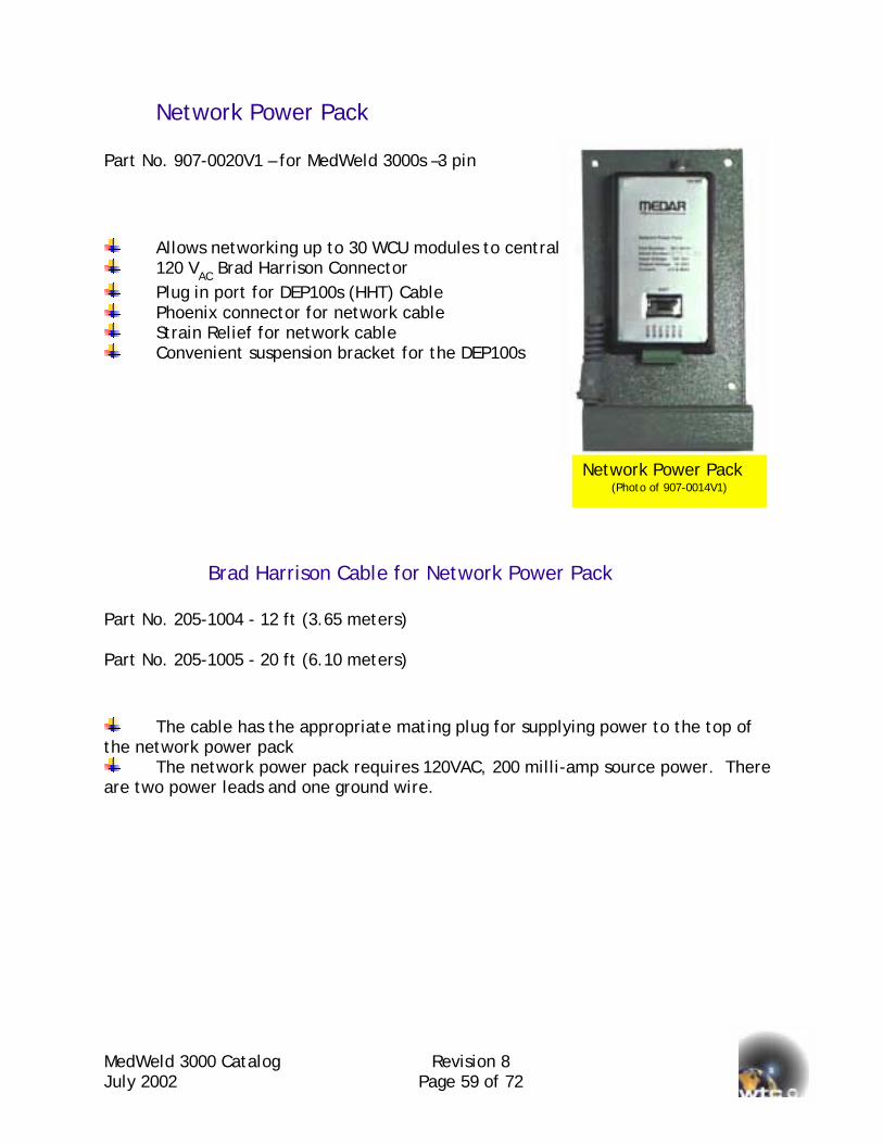
MedWeld 3000 Catalog Revision 8 July 2002 Page 59 of 72
Network Power Pack Part No. 907-0020V1 – for MedWeld 3000s –3 pin
Allows networking up to 30 WCU modules to central 120 VAC Brad Harrison Connector Plug in port for DEP100s (HHT) Cable Phoenix connector for network cable Strain Relief for network cable Convenient suspension bracket for the DEP100s
Brad Harrison Cable for Network Power Part No. 205-1004 - 12 ft (3.65 meters) Part No. 205-1005 - 20 ft (6.10 meters)
The cable has the appropriate mating plug for supplthe network power pack
The network power pack requires 120VAC, 200 milliare two power leads and one ground wire.
point
Pack
ying power to the top of
-amp source power. There
Network Power Pack (Photo of 907-0014V1)
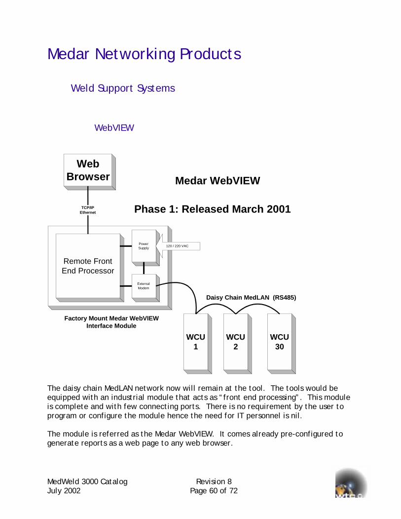
MedWeld 3000 Catalog Revision 8 July 2002 Page 60 of 72
Medar Networking Products
Weld Support Systems
WebVIEW
Remote Front End Processor
Power Supply
External Modem
120 / 220 VAC
WCU
1 WCU
2 WCU
30
Daisy Chain MedLAN (RS485)
Web
Browser
TCP/IP Ethernet
Medar WebVIEW
Phase 1: Released March 2001
Factory Mount Medar WebVIEW Interface Module
The daisy chain MedLAN network now will remain at the tool. The tools would be equipped with an industrial module that acts as “front end processing”. This module is complete and with few connecting ports. There is no requirement by the user to program or configure the module hence the need for IT personnel is nil. The module is referred as the Medar WebVIEW. It comes already pre-configured to generate reports as a web page to any web browser.

MedWeld 3000 CJuly 2002
Medar WebVIEW (Phase 1) WebVIEW consists of a remote front-end processor unit in a small industrial enclosure that is to be mounted near the welding tools. The FEP is a microprocessor-based device that has memory and communications channels. WebVIEW has complete software functionality in its first phase to behave as a stand-alone unit. Included below are some of these features.
WebVIEW Phase 1 Features:
Interface on MedLAN network (RS485) optically isolated up to 30 MedWeld controls.
Program / View sequences, setup and steppers. Program / Edit sequences, setup and steppers. Status / View all and individual steppers with print option. Status / Edit all and individual steppers with reset function. Information Status: Device ID of weld controls on line. Archiving (Saving) sequences, setup and steppers to computer. Archiving (Uploading) sequences, setup and steppers from computer. Log Welding Data, Faults, Events and Notices (100 items per weld control) View / Print / Save all log data
With the phase 1 WebVIEW, the user simply plugs in any computer having a web browser into the Ethernet port. Immediately, a user interface screen will appear with prompting buttons that will allow navigation in the collection of welding information.
Sample page of WebVIEW
atalog Revision 8 Page 61 of 72
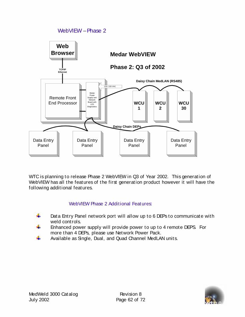
MedWeld 3000 Catalog Revision 8 July 2002 Page 62 of 72
WebVIEW – Phase 2
Remote Front End Processor
Medar Power
Supply and Network
Board with LED
Diagnostics
120 / 220 VAC
Web
Browser
TCP/IP Ethernet
Medar WebVIEW
Phase 2: Q3 of 2002
WCU 1
WCU 2
WCU 30
Daisy Chain MedLAN (RS485)
Data Entry Panel
Daisy Chain DEPs
Data Entry Panel
Data Entry Panel
Data Entry Panel
WTC is planning to release Phase 2 WebVIEW in Q3 of Year 2002. This generation of WebVIEW has all the features of the first generation product however it will have the following additional features.
WebVIEW Phase 2 Additional Features:
Data Entry Panel network port will allow up to 6 DEPs to communicate with weld controls.
Enhanced power supply will provide power to up to 4 remote DEPS. For more than 4 DEPs, please use Network Power Pack.
Available as Single, Dual, and Quad Channel MedLAN units.

MedWeld 3000 Catalog Revision 8 July 2002 Page 63 of 72
Weld Support Systems (Bank System Software) The Medar WebVIEW product is a product that can stand by itself. Users would simply use the WebVIEW with a computer or other device that has web-browsing software. The user interacts with the MedWeld controls as the user navigates through the various screens of the WebVIEW. For users who want to automate the interaction above the remote FEP device, WTC has available WSS NT System Software to automate interfaces with user interface and the welding controls networked via the WebVIEW or other network interfaces.

MedWeld 3000 Catalog Revision 8 July 2002 Page 64 of 72
Sizing Circuit Breaker and Isolation Contactors
RULES FOR SELECTING CIRCUIT BREAKER FRAME SIZES By Jack Farrow, WTC R&D Center July 7, 1993 rev. 11/3/95, 8/6/97 and 2/7/01 For WTC Resistance Welding Controls
DISCLAIMER: The purpose of this document is to assist in selecting the proper size circuit breaker for a given welding application. This document does not constitute any recommendation, warranty or obligation on the part of WTC or any of its employees. The user of this information assumes all responsibility for proper use of the information. The information in this document is presented as-is; no warranty of correctness or suitability for any application is given or implied.
ASSUMPTIONS: The first part of this selection guide relates to the computation of the minimum required circuit breaker frame size based upon the considerations of average current. The second part relates to the computation of the required magnetic trip current range. The circuit breaker can then be selected so that it meets both requirements. This selection guide assumes the following things: The circuit breakers are magnetic-trip only (no thermal trip) and the magnetic trip current range is adjustable from at least 4 times nominal circuit breaker rating up to at least 8 times nominal circuit breaker rating. For a 250-amp circuit breaker, this means a magnetic trip adjustment range of 1000 to 2000 amps. The KVA ratings on the nameplates of the welding transformers are in accordance with the RWMA standards for resistance welding transformers. The power line voltage is between 440 and 500 VAC nominal. When two or more welding transformers are connected to the same welding control and are fired simultaneously, the effective transformer KVA is the sum of all the transformers that are fired simultaneously. In multiple-transformer cascading applications, the effective transformer KVA is the KVA rating of the largest transformer, NOT the sum of all of them. All calculations here apply to SINGLE-PHASE welding controls only.
MedWeld 3000 Catalog Revision 8 July 2002 Page 65 of 72
PART 1: CIRCUIT BREAKER MINIMUM FRAME SIZE SELECTION GUIDE There are three classes of duty cycle to consider: A HIGH duty cycle application is seam welding. For HIGH DUTY CYCLE applications, the circuit breaker size should be: CIRCUIT BREAKER SIZE (amps) = TRANSFORMER NAMEPLATE KVA x 2 A MEDIUM duty cycle application is defined as 7 spot welds or more in any 30-second time interval. This corresponds to a duty cycle of more than 5%. Robot applications, manually operated welders, or multi-transformer cascading controls usually fall into this category. For MEDIUM DUTY CYCLE applications, the circuit breaker size should be: CIRCUIT BREAKER SIZE (amps) = TRANSFORMER NAMEPLATE KVA X 1.6 A LOW duty cycle application is defined as 6 or fewer spot-welds in any 30-second time interval. This corresponds to a duty cycle of 5% or less. Welders on fixtures or hard automation usually fall into this category. For LOW DUTY CYCLE applications, the circuit breaker size should be: CIRCUIT BREAKER SIZE (amps) = TRANSFORMER NAMEPLATE KVA X 1.3 The result of the calculation of PART 1 sets the MINIMUM acceptable circuit breaker frame size, based on average current considerations. Depending upon the results of the computation for the required magnetic trip setting (PART 2), a larger circuit breaker may be required.

MedWeld 3000 Catalog Revision 8 July 2002 Page 66 of 72
PART 2: MAGNETIC TRIP RANGE SELECTION. The selection of magnetic trip range is determined by maximum peak current draw, not duty cycle or average current. In order to compute maximum peak current draw, maximum welding current, type of welding machine, and number of welds made simultaneously need to be known. The following generalizations are biased toward worst-case; they will usually indicate a need for a higher magnetic trip range than what is actually needed. These generalizations should be used ONLY if better data is not available. The basic formula for selecting the required magnetic trip setting is:
MTS = WC * NSW * MF Where:
MTS = Magnetic trip setting WC = Welding current per weld; assume 18,000 amps for steel, and 40,000
amps for aluminum NSW = Number of simultaneous weld loops. Usually, this is equal to the
number of weld spots. Where series welding is used, each pair of weld spots counts as one.
MF = Machine factor; 0.084 for a hanging gun station, 0.042 for a machine or fixture welder, 0.021 for an integral transformer welding gun. EXAMPLE: Assume that four welds on a steel automobile body are made simultaneously in a fixture-type welding machine. Using these assumptions: WC = 18,000 amps (for steel) NSW = 4 (4 welds made simultaneously) MF = 0.042 (for a fixture welder) The required magnetic trip setting would be: MTS = 18,000 * 4 * 0.042 = 3042 amps If the required magnetic trip setting is higher than what is available on a circuit breaker frame size selected according to the first part of this write-up, a larger circuit breaker is required. The circuit breaker size should be selected according to EITHER average current or peak current considerations, whichever is higher.

MedWeld 3000 Catalog Revision 8 July 2002 Page 67 of 72
RULES FOR SIZING ISOLATION CONTACTORS By Jack Farrow, WTC R&D Center, February 7, 2001 Copyright, 2001 by WTC FOR WTC RESISTANCE WELDING CONTROLS
DISCLAIMER: The purpose of this document is to assist in selecting the proper size isolation contactor for a given welding application. This document does not constitute any recommendation, warranty or obligation on the part of Welding Technology Corporation or any of its employees, representatives or distributors. The user of this information assumes all responsibility for proper use of the information. The information in this document is presented as-is; no warranty of correctness or suitability for any application is given or implied. The calculations in this document have been simplified and are designed for the most common situations. If the application is very unusual, for example a system with large welding transformers above 400 KVA, a system with more than six welding transformers, or a system with a very low welding duty cycle (below 1%), competent engineering help should be sought to size the isolation contactor.
ASSUMPTIONS: The process to select the correct size of an isolation contactor consists of two parts. Part 1 calculates the average primary current draw of each welding transformer in the system. Given the average primary current draw of each welding transformer in the system and how they are connected, Part 2 selects the appropriate size isolation contactor. This selection guide assumes the following things: The isolation contactors are rated in amperes by UL general purpose current, which is a continuous-duty current. The isolation contactors are not opened or closed while weld current is flowing. The KVA ratings on the nameplates of the welding transformers are in accordance with the RWMA standards for resistance welding transformers. The power line voltage is between 420 and 500 VAC nominal. All calculations here apply to SINGLE-PHASE AC welding transformers only.
MedWeld 3000 Catalog Revision 8 July 2002 Page 68 of 72
PART 1:CALCULATION OF AVERAGE CURRENT DRAW PER WELDING TRANSFORMER There are three classes of duty cycle to consider: A HIGH duty cycle application is seam welding. For HIGH DUTY CYCLE applications, the average primary current draw per transformer is: AVERAGE CURRENT DRAW (amps) = TRANSFORMER NAMEPLATE KVA x 2 A MEDIUM duty cycle application is defined as 7 or more spot-welds in any 30-second time interval. This corresponds to a duty cycle of more than 5%. Robot applications, portable gun welders, or systems, which use multiple welding guns on each transformer usually, fall into this category. For MEDIUM DUTY CYCLE applications, the average primary current draw per transformer is: AVERAGE CURRENT DRAW (amps) = TRANSFORMER NAMEPLATE KVA X 1.6 A LOW duty cycle application is defined as 6 or fewer spot-welds in any 30-second time interval. This corresponds to a duty cycle of 5% or less. Manually operated pedestal welders, welders on fixtures or hard automation welders usually fall into this category. For LOW DUTY CYCLE applications, the average primary current draw per transformer is: AVERAGE CURRENT DRAW (amps) = TRANSFORMER NAMEPLATE KVA X 1.3 The result of the calculation of PART 1 determines the average current per welding transformer. Depending on how the transformer(s) are connected to the isolation contactor, PART 2 selects the appropriate isolation contactor rating in amperes.

MedWeld 3000 Catalog Revision 8 July 2002 Page 69 of 72
PART 2: ISOLATION CONTACTOR CURRENT RATING SELECTION BASED ON TRANSFORMER CONNECTION.
CASE 1: (simplest) If just one single-phase transformer is connected to an isolation contactor, the required isolation contactor current rating is the value of average current calculated for that transformer from Part 1. CASE 2: If two or more transformers are connected in parallel on the same two poles of an isolation contactor and are welding simultaneously, the required isolation contactor current rating is simply the sum of the average currents calculated for each transformer (from Part 1). For example if three 50 KVA welding transformers, welding simultaneously in a fixture application are connected to the same two poles of an isolation contactor, the required current rating for the isolation contactor is: 65 + 65 + 65 = 195 amperes. CASE 3: If two or more transformers are connected in parallel on the same two poles of an isolation contactor and ARE NOT welding simultaneously (cascade operation), the required isolation contactor current rating is equal to the average current for the largest transformer (from Part 1) times the square root of the number of transformers. For example, if a 100 KVA and a 75 KVA transformer are connected in parallel to the same two poles of an isolation contactor and are operated in cascade in a fixture welding application, the required current rating for the isolation contactor is: 130 * sqrt(2) = 184 amperes.

MedWeld 3000 Catalog Revision 8 July 2002 Page 70 of 72
CASE 4: If two or more transformers are connected to different poles of the isolation contactor (three-phase operation), whether the transformers are welding simultaneously or not, the required isolation contactor current rating is the highest sum of average currents for the all the transformers on one phase, times 1.7 (the approximate square root of 3). For example, four 75 KVA fixture welding transformers are connected to all three poles of an isolation contactor. Two transformers are connected to poles 1 and 2, one transformer is connected to poles 2 and 3, and the last transformer is connected to poles 1 and 3. All transformers weld simultaneously: The largest load is the two 75 KVA transformers on poles 1 and 2. The computed average current (from Part 1) for these two transformers is 98 + 98 = 196 amperes. The required current rating for the isolation contactor is: 196 * 1.7 = 333 amperes Once the required current rating is computed, select the isolation contactor with the next-higher current rating value. The circuit breaker above the isolation contactor(s) and any upstream fuses must be sized appropriately to handle the required current ratings computed above. The magnetic trip of the circuit breaker should be set no higher than ten times the current rating of the smallest isolation contactor below it.

MedWeld 3000 Catalog RevisioJuly 2002 Page 71
Directory of Resources WTC - Corporate Office
WTC Automotive
WTC Canada
Technitron Industrial Division
Industrial Technical Services Div
150 St. Charles Road Carol Stream IL 60188-2083 Tel: 630-462-8250 Fax: 630-462-8259 Email: [email protected]: www.weldtechcorp.com
24775 Crestview Court Farmington Hills, MI 48335-1563 Tel: +1 248-477-3900 Fax: +1 248-477-8897 Email: [email protected] Web: www.weldtechcorp.com
240 Cordova Road P.O. Box 858 Oshawa, Ontario L1H 7N1Tel: +1 905-433-1230 Fax: +1 905-433-1257 Email: [email protected]
710 Cahaba Valley Circle Pelham, Alabama 35124 Tel: +1 205-989-5700 Fax: +1 205-989-5719 Email: [email protected]
ision
24775 Crestview Court Farmington Hills, MI 48335-1563Tel: +1 877-982-7378 (toll free) Fax: +1 248-477-5263 Email: [email protected]n 8 of 72

MedWeld 3000 Catalog Revision 8 July 2002 Page 72 of 72
Quality QS 9000 with TE Supplement
Medar and other WTC brand welding controls are manufactured in WTC’s Farmington Hills, Michigan facility. BSI registers this facility along with the WTC Canada facility and ITS in Farmington Hills Michigan under certificate FM52727 for QS9000 with TE Supplement.
Acknowledgements
Allen-Bradley, PLC, SLC500 are registered trademarks of Rockwell Automation Fanuc is a registered trademark of Fanuc Robotics Medar, MedWeld and WebVIEW are trademarks of Welding Technology Corporation. Motoman is a registered trademark of Yaskawa Electric. Nachi is a registered trademark of Nachi Robotics Systems, Inc.
The symbol is a registered trademark of CSA International
The mark certifies conformity with all applicable European Community requirements.