eVD4 - Breaker integrated protection RBX615 - Engineering guide.pdf
Medium voltage products
eVD4 – RBX615Application manual
RBX615 Standard configurations 1
1. Protection functions 3
1.1. Overcurrent protection 3
1.2. Thermal protection 3
1.3. Motor stall protection 4
1.4. Loss of load protection 4
1.5. Earth fault protection 4
1.6. Phase discontinuity protection 5
1.7. Unbalance protection 5
1.8. Overvoltage protection 5
1.9. Negative phase sequence current 6
1.10. Undervoltage protection 6
1.11. Residual overvoltage protection 6
1.12. Motor startup supervision 7
2. Protection related functions 8
2.1. Circuit-breaker failure protection 8
2.2. K86 master trip 8
2.3. Emergency start 8
3. Supervision functions 9
3.1. Trip coil and current circuit supervisions 9
4. Condition monitoring functions 10
4.1. Circuit-breaker monitor alarm 10
4.2. Motor runtime counter 10
5. Control functions 11
5.1. Circuit-breaker control 11
5.2. Earthing switch control 12
5.3. Withdrawable motorized truck control 13
5.4. Autorecloser 13
6. Measurement function 14
6.1. Digital fault recorder 14
7. General logics 15
7.1. Local/remote selector 15
7.2. Circuit-breaker open command 15
7.3. Circuit-breaker close command 16
7.4. Enable close operation 16
7.5. Enable close operation with motor 17
8. Inputs and Outputs 18
8.1. Inputs 18
8.2. Outputs 19
9. LEDs 20
9.1. LEDs (feeder protection) 20
9.2. LEDs (motor protection) 22
10. Cumulative blocks 23
10.1. Cumulative start 23
10.2. Cumulative operate 23
10.3. Cumulative alarm 23
11. Variants 24
11.1. Fixed version 24
11.2. Motorized truck version 24
11.3. No auto-reclose function 24


11
RBX615 Standard configurations
RBX615 is available in five standard configurations: Feeder 1, 2, 3 and Motor 1, 2. The standard signal configuration can be changed by means of the graphical signal matrix or the optional graphical application functionality of the Protection and Control IED Manager PCM600. Further, the application configuration functionality of PCM600 supports the creation of multi-layer logic functions using various logical elements, including timers and flip-flops. By combining protection functions with logic function blocks, the IED configuration can be adapted to user-specific application requirements.
Description Configuration
Non-directional overcurrent protection and non-directional earth fault protection Feeder 1 (F1)
Non-directional overcurrent protection and directional earth fault protection based on measurement of the phase voltages Feeder 2 (F2)
Directional overcurrent protection, directional earth fault protection based on measurement of the phase voltages and undervoltage and overvoltage protection Feeder 3 (F3)
Motor protection based on the current measurement Motor 1 (M1)
Motor protection based on the current and voltage measurements Motor 2 (M2)
Functions IEC 61850 IEC 60617 IEC-ANSI Pre-configurations
F1 F2 F3 M1 M2
Protections
Three-phase non-directional overcurrent protection, low stage PHLPTOC1 3I> (1) 51P-1 (1) • • - • •
Three-phase non-directional overcurrent protection, high stage PHHPTOC1 3I>> (1) 51P-2 (1) • • - - -
PHHPTOC2 3I>> (2) 51P-2 (2) • • - - -
Three-phase non-directional overcurrent protection, instantaneous stage PHIPTOC1 3I>>> (1) 50P/51P (1) • • • • •
Three-phase directional overcurrent protection, low stageDPHLPDOC1 3I> → (1) 67-1 (1) - - • - -
DPHLPDOC2 3I> → (2) 67-1 (2) - - • - -
Three-phase directional overcurrent protection, high stage DPHHPDOC1 3I>> → 67-2 - - • - -
Non-directional earth-fault protection, low stageEFLPTOC1 I0> (1) 51N-1 (1) • - - • -
EFLPTOC2 I0> (2) 51N-1 (2) • - - - -
Non-directional earth-fault protection, high stage EFHPTOC1 I0>> (1) 51N-2 (1) • • • • •
Non-directional earth-fault protection, instantaneous stage EFIPTOC1 I0>>> (1) 50N/51N (1) • - - - -
Directional earth-fault protection, low stageDEFLPDEF1 I0> → (1) 67N-1 (1) - • • - •
DEFLPDEF2 I0> → (2) 67N-1 (2) - • • - -
Directional earth-fault protection, high stage DEFHPDEF1 I0>> → 67N-2 - • • - -
Negative-sequence overcurrent protectionNSPTOC1 I2> (1) 46 (1) • • • • •
NSPTOC2 I2> (2) 46 (2) • • • • •Phase discontinuity protection PDNSPTOC1 I2/I1> 46PD • • • - -
Residual overvoltage protection
ROVPTOV1 U0> (1) 59G (1) - • • - -
ROVPTOV2 U0> (2) 59G (2) - • • - -
ROVPTOV3 U0> (3) 59G (3) - • • - -
Three-phase undervoltage protection
PHPTUV1 3U< (1) 27 (1) - - • - •
PHPTUV2 3U< (2) 27 (2) - - • - -
PHPTUV3 3U< (3) 27 (3) - - • - -
Three-phase overvoltage protection
PHPTOV1 3U> (1) 59 (1) - - • - -
PHPTOV2 3U> (2) 59 (2) - - • - -
PHPTOV3 3U> (3) 59 (3) - - • - -
Three-phase positive-sequence undervoltage protection PSPTUV1 U1< 47U+ - - • - •Three-phase negative-sequence overvoltage protection NSPTOV1 U2> 47O- - - • - •
Three-phase thermal protection for feeders, cables and distribution transformers T1PTTR1 3Ith>F 49F • • • - -
Negative-sequence overcurrent protection for motorsMNSPTOC1 I2>M (1) 46M (1) - - - • •
MNSPTOC2 I2>M (2) 46M (2) - - - • •
Underpower protection LOFLPTUC1 3I< 37 - - - • •Rotor block JAMPTOC1 Ist> 51LR - - - • •Motor start-up STTPMSU1 Is2t n< 49,66,48,51LR - - - • •Protection against phase reversal PREVPTOC I2>> 46R - - - • •Three-phase thermal overload for motors MPTTR1 3Ith>M 49M - - - • •
Circuit-breaker fault CCBRBRF1 3I>/I0>BF 51BF/51NBF • • • • •
Three-phase inrush current detector INRPHAR1 3I2f> 68 • • • - -
• available O on request

22
Functions IEC 61850 IEC 60617 IEC-ANSI Pre-configurations
F1 F2 F3 M1 M2
Control
Trip managementTRPPTRC1 Master Trip (1) 94/86 (1) • • • • •
TRPPTRC2 Master Trip (2) 94/86 (2) • • • • •
Fixed circuit-breaker control FCBXCBR1 I ↔ O CB I ↔ O CB • • • • •
Withdrawable circuit-breaker control WCBXCBR1 I ↔ O CB I ↔ O CB • • • • •
Earthing switch indication ESSXSWI1 I ↔ O ES I ↔ O ES • • • • •
Earthing switch control MESXSWI1 I ↔ O ES I ↔ O ES • • • • •
Truck control TRXSWI I ↔ O DC I ↔ O DC • • • • •
H-Bridge controlHBGAPC1 HBC HBC • • • • •
HBGAPC2 HBC HBC • • • • •
Emergergency startup ESMGAPC1 ESTART ESTART - - - • •
Auto-reclosing DARREC1 O → I 79 O O O - -
Supervision and monitoring
Circuit-breaker condition monitoring SSCBR1 CBCM CBCM • • • • •
Coil switch supervision (Open) OCSSCBR1 TCS (Open) TCM (Open) • • • • •
Coil switch supervision (Close) CCSSCBR1 TCS (Close) TCM (Close) • • • • •
Fuse failure supervision SEQRFUF1 FUSEF 60 - - • - •
Motor runtime counter MDSOPT1 OPTS OPTM - - - • •
Measurement
Disturbance recorder RDRE1 - - • • • • •
Three-phase current measurement CMMXU1 3I 3I • • • • •
Sequence current measurement CSMSQI1 I1, I2, I0 I1, I2, I0 • • • • •
Residual current measurement RESCMMXU1 I0 In • • • • •
Three-phase voltage measurement VMMXU1 3U 3U - • • - •Residual voltage measurement RESVMMXU1 U0 Vn - • • - •Sequence voltage measurement VSMSQI1 U1, U2, U0 U1, U2, U0 - • • - •Three-phase power and energy measurement PEMMXU1 P, E P, E - • • - •Sensor temperature VDSTMP VDTS VDTM - • • - •
Presentation of standard configurations
The functional diagrams describe the IED's functionality from the protection, measuring, condition monitoring, disturbance recording, control and interlocking perspectives. The diagrams show the default functionality with simple symbol logics forming principle diagrams. Protection function blocks are part of the functional diagrams; they are identified on the basis of their IEC 61850 name. Some function blocks, such as PHHPTOC, are used several times in the configuration. To separate the blocks from each other, the IEC 61850 name, IEC symbol and ANSI function number are appended with a running number, that is, an instance number, from one upwards. With the Signal Matrix and Application Configuration in PCM600, it is possible to modify the standard configuration according to the actual needs. The IED is delivered from the factory with default connections described in the functional diagrams for binary inputs, binary outputs, function-to-function connections and alarm LEDs. The Signal Matrix is used for GOOSE signal input engineering and for making cross-references between the physical I/O signals and the function blocks. The Signal Matrix tool cannot be used for adding or removing function blocks, for example, GOOSE receive function blocks.
• available O on request
33
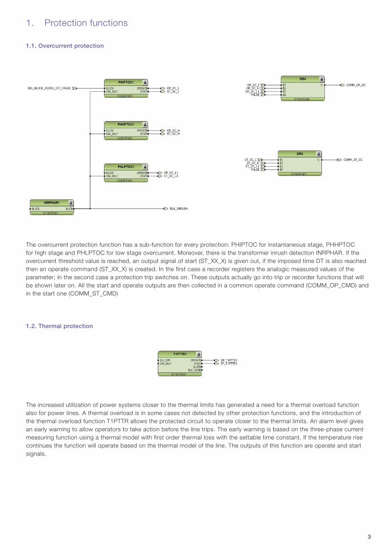
The overcurrent protection function has a sub-function for every protection: PHIPTOC for instantaneous stage, PHHPTOC for high stage and PHLPTOC for low stage overcurrent. Moreover, there is the transformer inrush detection INRPHAR. If the overcurrent threshold value is reached, an output signal of start (ST_XX_X) is given out, if the imposed time DT is also reached then an operate command (ST_XX_X) is created. In the first case a recorder registers the analogic measured values of the parameter; in the second case a protection trip switches on. These outputs actually go into trip or recorder functions that will be shown later on. All the start and operate outputs are then collected in a common operate command (COMM_OP_CMD) and in the start one (COMM_ST_CMD)
1.2. Thermal protection
1. Protection functions
1.1. Overcurrent protection
The increased utilization of power systems closer to the thermal limits has generated a need for a thermal overload function also for power lines. A thermal overload is in some cases not detected by other protection functions, and the introduction of the thermal overload function T1PTTR allows the protected circuit to operate closer to the thermal limits. An alarm level gives an early warning to allow operators to take action before the line trips. The early warning is based on the three-phase current measuring function using a thermal model with first order thermal loss with the settable time constant. If the temperature rise continues the function will operate based on the thermal model of the line. The outputs of this function are operate and start signals.

44
The stalled motor protection JAMPTOC is used for protecting the motor in stall or mechanical jam situations during the running state. When the motor is started, a separate function is used for the startup protection (STTPMSU) and JAMPTOC is normally blocked during the startup period. When the motor has passed the starting phase, JAMPTOC monitors the magnitude of phase currents. The function starts when the measured current exceeds the breakdown torque level, that is, above the set limit.
1.4. Loss of load protection
The loss of load protection LOFLPTUC is used to detect a sudden load loss which is considered as a fault condition. LOFLPTUC starts when the current is less than the set limit. It operates with the definite time (DT) characteristics, which means that the function operates after a predefined operate time and resets when the fault current disappears.
1.5. Earth fault protection
1.3. Motor stall protection
The earth fault protection is divided in three sub-functions, each one for a specific protection code: DEFHPDEF for directional earth-fault protection high stage, DEFLPDEF for directional earth-fault protection low stage and EFHPTOC for non-directional earth-fault protection high stage. As usual there are the operate and start commands which are later collected in the common ones.

55
The three-phase overvoltage protection PHPTOV is applied on power system elements, such as generators, transformers, motors and power lines, to protect the system from excessive voltages that could damage the insulation and cause insulation breakdown. The three-phase overvoltage function includes a settable value for the detection of overvoltage either in a single phase, two phases or three phases. PHPTOV includes both definite time (DT) and inverse definite minimum time (IDMT) characteristics for the delay of the trip. As with the other protection blocks, it has 2 outputs signals of operate and start.
The phase discontinuity protection PDNSPTOC is used for detecting unbalance situations caused by broken conductors. The function starts and operates when the unbalance current I2/I1 exceeds the set limit. I1 and I2 represent positive and negative phase sequence currents. As before, it gives out start and operate commands.
1.7. Unbalance protection
The unbalance protection, based on negative-phase-sequence current function MNSPTOC, protects electric motors from phase unbalance. A small voltage unbalance can produce a large negative-sequence current flow in the motor. For example, a 5 percent voltage unbalance produces a stator negative-sequence current of 30 percent of the full load current, which can severely heat the motor. MNSPTOC detects the large negative-sequence current and disconnects the motor.
1.8. Overvoltage protection
1.6. Phase discontinuity protection
66
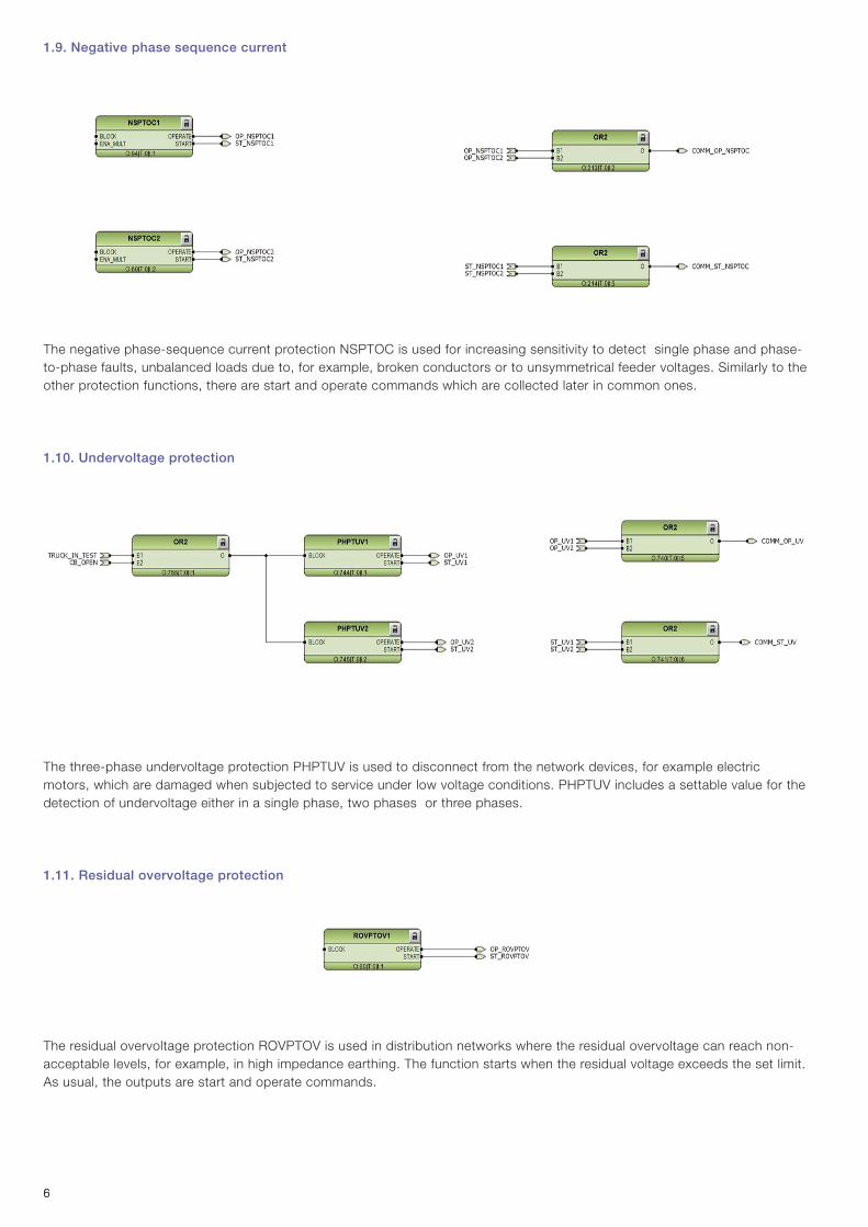
The negative phase-sequence current protection NSPTOC is used for increasing sensitivity to detect single phase and phase-to-phase faults, unbalanced loads due to, for example, broken conductors or to unsymmetrical feeder voltages. Similarly to the other protection functions, there are start and operate commands which are collected later in common ones.
1.10. Undervoltage protection
The three-phase undervoltage protection PHPTUV is used to disconnect from the network devices, for example electric motors, which are damaged when subjected to service under low voltage conditions. PHPTUV includes a settable value for the detection of undervoltage either in a single phase, two phases or three phases.
1.11. Residual overvoltage protection
1.9. Negative phase sequence current
The residual overvoltage protection ROVPTOV is used in distribution networks where the residual overvoltage can reach non-acceptable levels, for example, in high impedance earthing. The function starts when the residual voltage exceeds the set limit. As usual, the outputs are start and operate commands.

77
The motor startup supervision function STTPMSU is designed for protection against excessive starting time and locked rotor conditions of the motor during starting. For good and reliable operation of motor, the thermal stress during the motor starting is maintained within the allowed limits. The starting of motor is supervised by monitoring the TRMS magnitude of all the phase currents or by monitoring the status of the circuit-breaker connected to the motor. STTPMSU also protects the motor from an excessive number of startups. Upon exceeding the specified number of startups within a certain duration, STTPMSU blocks further starts. The restart of the motor is also inhibited after each start and continues to be inhibited for a set duration. When the motor start lock is enabled, STTPMSU gives the time remaining until the restart of the motor. In the case of an emergency start, the logic does not block the motor startup. The outputs of this block deal with the operate/trip signals due to thermal stress and stalling protection (OPR_IIT and OPR_STALL), the signal of motor startup in progress (MOT_START) and the lockout condition (LOCK_START).
1.12. Motor startup supervision
88
2. Protection related functions
2.1. Circuit-breaker failure protection
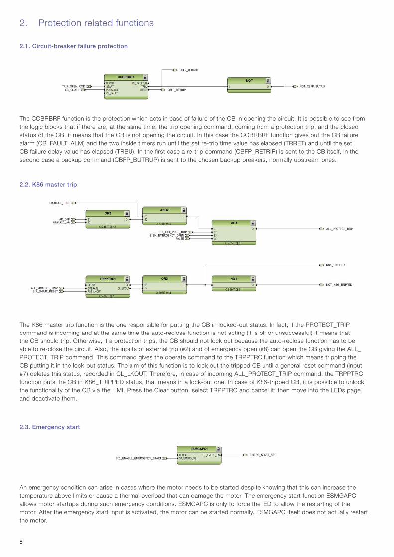
The CCBRBRF function is the protection which acts in case of failure of the CB in opening the circuit. It is possible to see from the logic blocks that if there are, at the same time, the trip opening command, coming from a protection trip, and the closed status of the CB, it means that the CB is not opening the circuit. In this case the CCBRBRF function gives out the CB failure alarm (CB_FAULT_ALM) and the two inside timers run until the set re-trip time value has elapsed (TRRET) and until the set CB failure delay value has elapsed (TRBU). In the first case a re-trip command (CBFP_RETRIP) is sent to the CB itself, in the second case a backup command (CBFP_BUTRUP) is sent to the chosen backup breakers, normally upstream ones.
2.2. K86 master trip
The K86 master trip function is the one responsible for putting the CB in locked-out status. In fact, if the PROTECT_TRIP command is incoming and at the same time the auto-reclose function is not acting (it is off or unsuccessful) it means that the CB should trip. Otherwise, if a protection trips, the CB should not lock out because the auto-reclose function has to be able to re-close the circuit. Also, the inputs of external trip (#2) and of emergency open (#8) can open the CB giving the ALL_PROTECT_TRIP command. This command gives the operate command to the TRPPTRC function which means tripping the CB putting it in the lock-out status. The aim of this function is to lock out the tripped CB until a general reset command (input #7) deletes this status, recorded in CL_LKOUT. Therefore, in case of incoming ALL_PROTECT_TRIP command, the TRPPTRC function puts the CB in K86_TRIPPED status, that means in a lock-out one. In case of K86-tripped CB, it is possible to unlock the functionality of the CB via the HMI. Press the Clear button, select TRPPTRC and cancel it; then move into the LEDs page and deactivate them.
2.3. Emergency start
An emergency condition can arise in cases where the motor needs to be started despite knowing that this can increase the temperature above limits or cause a thermal overload that can damage the motor. The emergency start function ESMGAPC allows motor startups during such emergency conditions. ESMGAPC is only to force the IED to allow the restarting of the motor. After the emergency start input is activated, the motor can be started normally. ESMGAPC itself does not actually restart the motor.
99
3. Supervision functions
3.1. Trip coil and current circuit supervisions
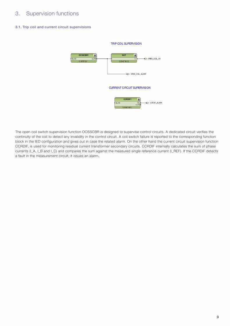
The open coil switch supervision function OCSSCBR is designed to supervise control circuits. A dedicated circuit verifies the continuity of the coil to detect any invalidity in the control circuit. A coil switch failure is reported to the corresponding function block in the IED configuration and gives out in case the related alarm. On the other hand the current circuit supervision function CCRDIF, is used for monitoring residual current transformer secondary circuits. CCRDIF internally calculates the sum of phase currents (I_A, I_B and I_C) and compares the sum against the measured single reference current (I_REF). If the CCRDIF detects a fault in the measurement circuit, it issues an alarm.

1010
4. Condition monitoring functions
4.1. Circuit-breaker monitor alarm
The circuit-breaker condition monitoring function (SSCBR) is used to monitor different parameters of the circuit-breaker. The breaker requires maintenance when the number of operations has reached a predefined value. For proper functioning of the circuit-breaker, it is essential to monitor the circuit-breaker operation, spring charge indication, breaker wear, travel time, number of operation cycles and accumulated energy. The energy is calculated from the measured input currents as the sum of current phases values. Alarms are generated when the calculated values exceed the threshold settings. Specifically, the inputs of this function are the information on the CB status coming from the CB function, such as the position of the CB (open or closed) and the condition of the spring (charged, discharged). The SSCBR function monitors a large variety of parameters and gives out an alarm for every warning condition. For example, alarms related to excessive travel time of CB opening or closing (TRV_T_OP_ALM, TRV_T_CL_ALM), failure in spring recharging (SPR_CHR_ALM), threshold value of operations done by the CB (CB_OPR_ALM), residual life based on tripping current value (CB_LIFE_ALM), long CB non-operating time (MON_ALM). All these outputs are therefore the alarms related to the good operability of the CB and the need for some maintenance.
4.2. Motor runtime counter
The motor runtime counter function MDSOPT calculates the accumulated operation time of the motor. The unit of time for accumulation is hour. The function generates a warning and an alarm when the accumulated operation time exceeds the set limits.

1111
5. Control functions
5.1. Circuit-breaker control
The circuit-breaker control function WCBXCBR is intended for withdrawable circuit-breaker control and status information purposes. This function executes commands and evaluates block conditions and different time supervision conditions. The function performs an execution command only if all the conditions indicate that a switch operation is allowed. The actuation of the command consists of operating the open and closed shunt releases. WCBXCBR is also assigned to monitor the truck status. Actually, if all the conditions to operate the truck are satisfied (CB and earthing switch open, truck moving input command enabled), the truck itself is allowed to move. Otherwise the CB function will block the RL2 not permitting the insertion of the truck. Other commands are the possibility to open ENA_OPEN (always on) or to close, depending on the admission of the CLOSE_ENABLE command; these two operations can also be blocked. The previously analyzed open command, on the other hand, gives the signal of the CB opening, whereas the close command will be explained later on. All these signals, however, act on the authorization of opening or closing the CB along with the right of blocking or unlocking the RL1 and RL2 coils. Regarding the outputs of this WCBXCBR function, there are mainly the ones related to the CB position (CB_OPEN and CB_CLOSE), which is detected by inductive position sensors and checked by the OKPOS (see the table), the charged spring indicator, the truck position (test or service, see the picture) checked by the TRUCK_OK and the status of the coils acting on RL1 and RL2 (released/not released).
ANSI truck symbols for the intermediate, service, test and faulty position
Status (POSITION) OPENPOS CLOSEPOS OKPOS
1=Open 1=True 0=False 1=True
2=Closed 0=False 1=True 1=True
3=Faulty/Bad (11) 1=True 1=True 0=False
0=Intermediate (00) 0=False 0=False 0=False

1212
5.2. Earthing switch control
The earthing switch indication function ESSXSWI indicates the open, closed and undefined states of the earthing switch. Before this function acts, there is a check for intermediate position of the earthing switch. Basically, it verifies that the command given is either “open position” or “closed position” to avoid intermediate status. In fact, the ESSXSWI function receives the signals and checks that there are not intermediate or faulty situations by comparing the values. As can be seen in the table, if the signals are coherent, the OKPOS check will give the output of open (ES_OPEN) or closed (ES_CLOSE), otherwise it will indicate the presence of an intermediate status or a faulty/bad execution.
These statuses are displayed on the HMI by means of standard single line diagram symbols, as shown below.
Earth Switch symbols for the intermediate, open, closed and faulty position
Status (POSITION) OPENPOS CLOSEPOS OKPOS
1=Open 1=True 0=False 1=True
2=Closed 0=False 1=True 1=True
3=Faulty/Bad (11) 1=True 1=True 0=False
0=Intermediate (00) 0=False 0=False 0=False

1313
5.3. Withdrawable motorized truck control
The truck control function TRXSWI is intended for truck control purposes. TRXSWI executes commands and evaluates block conditions and different time supervision conditions. The function performs an execution command only if all conditions indicate that a switch operation is allowed. The actuation of the command consists in controlling the H-Bridge driving the truck motor. The condition to operate the motor is the status of the truck: it should be enabled. So CB and ES should be open and the respective input #4 enabled. Once these conditions are satisfied, the TRXSWI function enables the H-Bridge and gives the moving direction. These commands are read by the HBGAPC function: this is a switching circuit used to apply a controlled voltage to a DC motor. The voltage applied across the motor can be either positive, that is, forward operation, or negative, that is, reverse operation. In case of an overcurrent or over-temperature signal, the function launches a fault alarm signal.
5.4. Autorecloser
About 80 to 85 percent of faults in MV overhead lines are transient and automatically cleared with a momentary de-energization of the line. The rest of the faults, 15 to 20 percent, can be cleared by longer interruptions. The de-energization of the fault location for a selected time period is implemented through automatic reclosing, during which most of the faults can be cleared. In case of a permanent fault, the automatic reclosing is followed by final tripping. A permanent fault must be located and cleared before the fault location can be re-energized. The function provides five programmable auto-reclose shots which can perform one to five successive auto-reclosings of desired type and duration, for instance one high-speed and one delayed auto-reclosing. This DARREC function receives as inputs the operate command from the different protection functions and some information related to the CB status, such as spring and open/closed statuses. The different operate commands are separated because in this way it is possible to set different delay times for the AR function. The output of this function is related to the AR operations themselves, such as the open command (OPEN_AR), the reclose one (RECLOSE_AR), the in progress status (AR_IN_PROG) and the status (AR_ON, AR_READY). Moreover, it also indicates the possible faults in the AR procedure, such as the locked status and the unsuccessful action.

1414
6. Measurement function
6.1. Digital fault recorder
The RDRE function is the one responsible for recording the signals coming from the transducers once the set threshold is elapsed: that is why it has as inputs the start commands of the various protections, along with the operate ones. Moreover, it also considers the status of the auto-reclose function and its possible commands.

1515
7. General logics
7.1. Local/remote selector
The local/remote selector function defines the type of control chosen, that is, whether we act from remote (e.g. digital inputs) or from local (HMI). The respective outputs specify this choice. To change this status from remote to local (and vice versa) use the R/L button on the HMI.
7.2. Circuit-breaker open command
The function that supervises the circuit-breaker open command is made up of two different blocks which may give that signal: the remote command and the trip due to the protections. In the first case, there should firstly be the remote opening input signal, then the truck in the service position and the remote status selected. In the case of protection trip, on the other hand, just one signal due to a protection system is enough to give the open command, such as the K86 master trip, the open phase of the auto-reclose function, or the PROTECTION_TRIP command (linked to various protections). If one of the two cases is on, there is the output of OPEN_COMMAND signal; in the specific case of open command due to a protection trip, there is also the TRIP_OPEN_CMD signal.
1616
7.3. Circuit-breaker close command
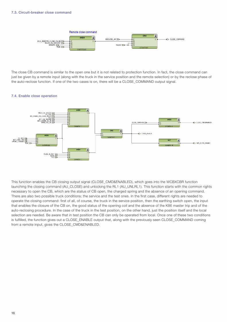
The close CB command is similar to the open one but it is not related to protection function. In fact, the close command can just be given by a remote input (along with the truck in the service position and the remote selection) or by the reclose phase of the auto-reclose function. If one of the two cases is on, there will be a CLOSE_COMMAND output signal.
7.4. Enable close operation
This function enables the CB closing output signal (CLOSE_CMD&ENABLED), which goes into the WCBXCBR function launching the closing command (AU_CLOSE) and unlocking the RL1 (AU_UNLRL1). This function starts with the common rights necessary to open the CB, which are the status of CB open, the charged spring and the absence of an opening command. There are also two possible truck conditions: the service and the test ones. In the first case, different rights are needed to operate the closing command: first of all, of course, the truck in the service position, then the earthing switch open, the input that enables the closure of the CB on, the good status of the opening coil and the absence of the K86 master trip and of the auto-reclosing procedure. In the case of the truck in the test position, on the other hand, just the position itself and the local selection are needed. Be aware that in test position the CB can only be operated from local. Once one of these two conditions is fulfilled, the function gives out a CLOSE_ENABLE output that, along with the previously seen CLOSE_COMMAND coming from a remote input, gives the CLOSE_CMD&ENABLED.
1717
7.5. Enable close operation with motor
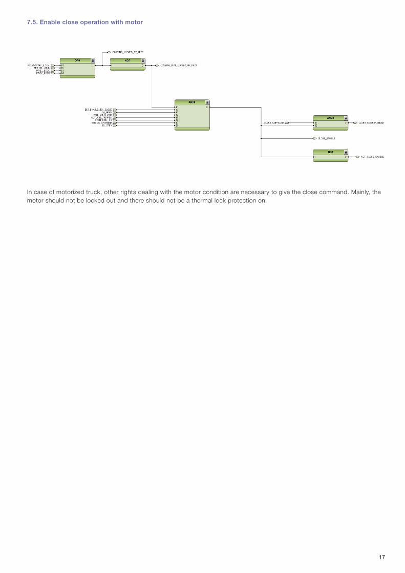
In case of motorized truck, other rights dealing with the motor condition are necessary to give the close command. Mainly, the motor should not be locked out and there should not be a thermal lock protection on.

1818
8. Inputs and outputs
8.1. Inputs
There are twelve digital inputs available in the plug. Each of them gives the related command used by the functions.
I/O Description
eVD4 - Binary Inputs
BI NumberWithout I/O
expansion module With I/O
expansion module Card Function Configurable
Available in plug
Bl 1 – • I/O expansion (-X200) Ext. Protections Alarm yes yes
Bl 2 – • I/O expansion (-X200) Ext. Protections Trip yes yes
Bl 3 – • I/O expansion (-X200) MCB closed yes yes
Bl 4 – • I/O expansion (-X200) Enable truk moving yes yes
Bl 5 – • I/O expansion (-X200) Enable to close in insert pos. yes yes
Bl 6 – • I/O expansion (-X200) Blocking OC inst. stage yes yes
Bl 7 – • I/O expansion (-X200) General Reset yes yes
Bl 8 – • I/O expansion (-X200) Emergency opening yes yes
Bl 9 – • I/O expansion (-X200) Earthing switch close yes yes
Bl 10 – • I/O expansion (-X200) Earthing switch open yes yes
Bl 11 • • Basic Card (-X300) CB remote closing no yes
Bl 12 • • Basic Card (-X300) CB remote opening no yes
Bl 13 • • Basic Card (-X300) CB closed signalling no no
Bl 14 • • Basic Card (-X300) CB open signalling no no
Bl 15 • • Basic Card (-X300) Springs charged signalling no no
Bl 16 • • Power Supply (-X100) Truck in test position no no
Bl 17 • • Power Supply (-X100) Truck in service position no no

1919
8.2. Outputs
In case of absence of the auto-reclose function, the respective output is available.
eVD4 - Binary Outputs BONumber
Without I/O expansion module
With I/O expansion module
Card Function ConfigurableAvailable
in plug
BO 1 – • I/O expansion (-X200) General operate indication yes yes
BO 2 – • I/O expansion (-X200) General start indication yes yes
BO 3 – • I/O expansion (-X200) Cumulative Alarm yes yes
BO 4 – • I/O expansion (-X200) Unsuccess AR yes yes
BO 5 • • Power Supply (-X100) K86 tripped yes yes
BO 6 • • Power Supply (-X100) CBFP open upstream yes yes
BO 7 • • Power Supply (-X100) Locking electromagnet on operating mechanism (-RLE1) no no
BO 8 • • Power Supply (-X100) Shunt closing release (-MBC) no no
BO 9 • • Power Supply (-X100) Shunt opening release (-MBO1) no no
BO 10 • • Power Supply (-X100) Watchdog no yes
BO 11 • • Power Supply (-X100) CB ready no yes
BO 12 • • Basic Card (-X300) Locking electromagnet on truck (-RLE2) no no

2020
9. LEDs
9.1. LEDs (feeder protection)

2121

2222
9.2. LEDs (motor protection)
LED Pages 1 and 3 are the same as the ones of Feeder protection. LED Page 2 is however different, as can be seen below.
2323
10. Cumulative blocks
10.1. Cumulative start
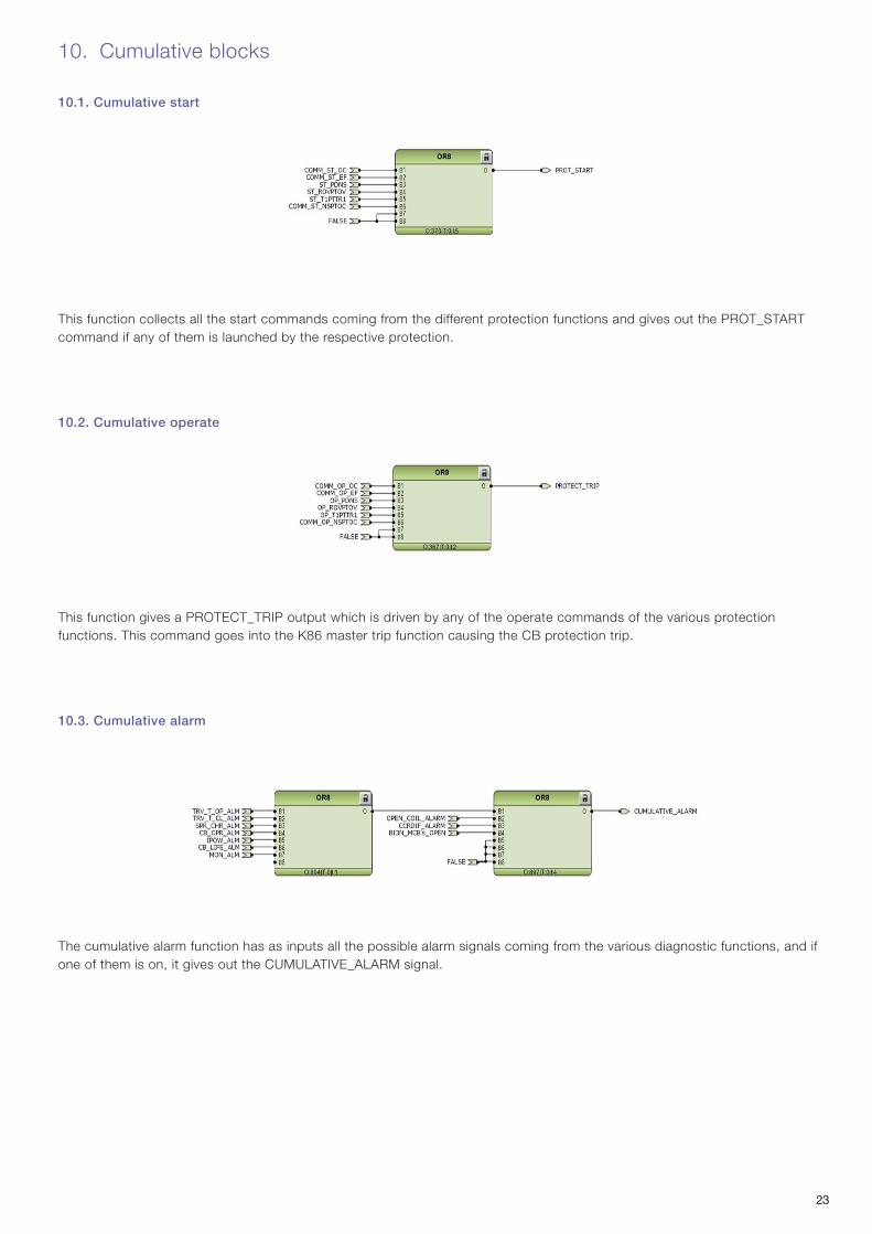
This function collects all the start commands coming from the different protection functions and gives out the PROT_START command if any of them is launched by the respective protection.
10.2. Cumulative operate
This function gives a PROTECT_TRIP output which is driven by any of the operate commands of the various protection functions. This command goes into the K86 master trip function causing the CB protection trip.
10.3. Cumulative alarm
The cumulative alarm function has as inputs all the possible alarm signals coming from the various diagnostic functions, and if one of them is on, it gives out the CUMULATIVE_ALARM signal.

2424
11. Variants
The blocks shown in this manual are as comprehensive as possible, however you may find some small differences with your configuration. But, the only variants you should be aware of regard the availability of some outputs or LEDs.
11.1. Fixed version
If you have an eVD4 - fixed version:• LEDs: there is no LED related to -RLE2. This LED is then available.• Input: #4 is available as there is no truck.
11.2. Motorized truck version
If you have an eVD4 with motorized truck:• Input: #4 is available as the motor is responsible for moving the truck.
11.3. No auto-reclose function
If you do not have the auto-reclose function configured:• Output: 1 is available as there no need for auto-reclose operation status.• LEDs: 2 are available for the same reason given in the previous point.

2525
1VC
D00
0420
– R
ev. -
, en
– A
ppl.
Man
ual -
201
1.07
(eV
D4-
RB
X61
5) (
gs) For more information please contact:
ABB S.p.A. Power Products DivisionUnità Operativa Sace-MVVia Friuli, 4I-24044 DalmineTel.: +39 035 6952 111Fax: +39 035 6952 874E-mail: [email protected]
ABB OyDistribution AutomationP.O. Box 699FI-65101 VAASA, FinlandPhone: +358 10 22 11Fax: +358 10 22 41094www.abb.com/substationautomation
ABB AG Calor Emag Medium Voltage Products Oberhausener Strasse 33 Petzower Strasse 8 D-40472 Ratingen D-14542 Glindow Phone: +49(0)2102/12-1230, Fax: +49(0)2102/12-1916
E-mail: [email protected]
www.abb.com
The data and illustrations are not binding. We reserve the right to make changes without notice in the course of technical development of the product.
© Copyright 2011 ABB. All rights reserved.