Medium Voltage Circuit Breaker Course Chapter 8.0 Student ...Medium Voltage Circuit Breaker Course...
14
Medium Voltage Circuit Breaker Course Chapter 8.0 Student Manual ABB HK Circuit Breakers USNRC 8-1 Rev 0 8.0 INTRODUCTION TO ABB/BBC/ITE HK CIRCUIT BREAKERS Learning Objectives Provide attendees with a basic understanding of the ABB HK breaker and its purpose, operation and construction. As a result of this lesson you will be able to understand: 1. The basic function of the HK circuit breaker 2. How the HK breakers are classed or grouped 3. How the breaker frame size method further identifies the breaker 4. The component attributes of the HK breaker: a. Chassis Mounting Arrangement b. Primary Contacts and Arc Chutes c. Electrical Devices including wiring d. Mechanical and Safety Interlocks e. Operating Mechanism 5. Basic understanding of common failure modes of HK Breakers 6. Basic understanding of maintenance scheduling 7. Basic understanding of subcomponent replacement 8. Basic understanding of design upgrades for the HK breakers 9. Proper lubrication type for HK breakers 10. Basic understanding of routine maintenance using the Preventative Maintenance Manual for the HK Circuit Breaker 8.1 WHAT IS AN HK CIRCUIT BREAKER? The HK breaker exclusively is a Horizontal “Draw out “design. It is an “ACB” (Air Circuit breaker) with a Spring Charged operating mechanism. This breaker is classed by Voltage class, Ampere size and Interrupting capacity.
Transcript of Medium Voltage Circuit Breaker Course Chapter 8.0 Student ...Medium Voltage Circuit Breaker Course...

Medium Voltage Circuit Breaker Course Chapter 8.0 Student Manual ABB HK Circuit Breakers
USNRC 8-1 Rev 0
8.0 INTRODUCTION TO ABB/BBC/ITE HK CIRCUIT BREAKERS
Learning Objectives
Provide attendees with a basic understanding of the ABB HK breaker and its purpose, operation and construction.
As a result of this lesson you will be able to understand:
1. The basic function of the HK circuit breaker
2. How the HK breakers are classed or grouped
3. How the breaker frame size method further identifies the breaker
4. The component attributes of the HK breaker:
a. Chassis Mounting Arrangement
b. Primary Contacts and Arc Chutes
c. Electrical Devices including wiring
d. Mechanical and Safety Interlocks
e. Operating Mechanism
5. Basic understanding of common failure modes of HK Breakers
6. Basic understanding of maintenance scheduling
7. Basic understanding of subcomponent replacement
8. Basic understanding of design upgrades for the HK breakers
9. Proper lubrication type for HK breakers
10. Basic understanding of routine maintenance using the Preventative Maintenance Manual for the HK Circuit Breaker
8.1 WHAT IS AN HK CIRCUIT BREAKER?
The HK breaker exclusively is a Horizontal “Draw out “design. It is an “ACB” (Air Circuit breaker) with a Spring Charged operating mechanism. This breaker is classed by Voltage class, Ampere size and Interrupting capacity.

Medium Voltage Circuit Breaker Course Chapter 8.0 Student Manual ABB HK Circuit Breakers
USNRC 8-2 Rev 0
8.2 HOW HK CIRCUIT BREAKERS ARE CLASSED
The HK breaker is made in several voltage classes. The HK breaker Nameplate provides breaker identification. For example:
5HK 250, 1200 Amp 5HK- 5 KV Voltage Class 250-Interrupting Capacity (MVA) 1200 Amp- Maximum continuous amperage
8.2.1 Voltage Class: HK Circuit breakers are grouped by voltage class that is
normally defined as MEDIUM. • Medium Voltage (5KV to 15KV): this includes 5HK, 7.5HK and 15HK
models. 8.2.2 Ampere Size: HK Circuit Breakers are grouped by “Frame Size” or
“Ampere Size”. This is determined by the Load circuit the breaker controls under normal use. The 5HK and 15HK breakers will most commonly be 1200 Amp, 2000 Amp or up to 3000 Amp.
8.2.3 Interrupting Capacity: HK Breakers are also grouped by its Maximum
Interrupting capacity or MVA. 250MVA to 1000 MVA.
8.3 MAJOR COMPONENT ATTRIBUTES FOR THE HK BREAKER
The HK breaker consists of the main chassis, contact assembles, a control panel, operating mechanism, racking mechanism, puffer assembly and various interlocks. The whole chassis is on wheels for ease of movement. The HK Circuit breaker is a “Draw Out” type; this means that the breaker is RACKED IN to its cubicle by means of racking handle.
8.3.1 Front cover, Insulator barriers, and Arc Chutes:
• The Front cover is a barrier between live parts of the breaker and personnel.

Medium Voltage Circuit Breaker Course Chapter 8.0 Student Manual ABB HK Circuit Breakers
USNRC 8-3 Rev 0
• Insulating barriers and cover- The Barriers isolate all the conductive parts of
the breaker from each other and the breaker frame
• Arc chutes- Consists of Blow Out coils, Arc Runners and ceramic insulators. The Arc chute breaks up the Arc by magnetic and thermal effects when the breaker OPENS under load by dividing the arc into segments aided by a puff of air.
8.3.2 The contact assemblies (Figure 8-1) are the main current carrying part of the breaker. The phase insulators (1 per phase) hold the contact bus and contacts. The HK contacts are a “BUTT” type design in that they “MAKE” flatly against each other (Figure 8-2).
8.3.3 The contacts assemblies consist of:
• Each phase has a plastic phase insulator, which holds the upper and lower contact bus. The bus is bolted to the insulator and can be removed (see Figure 8-1).
• Stationary arcing contacts- are mounted side-by-side sharing a common pivot pin on the upper contact bus. Designed to take the majority of the arc when the breaker opens under load. Typically made of a Silver Tungsten alloy or similar material. Arcing contacts always “MAKE” first and “BREAK” last. Intermediate “MAKE” before the Main on closing and “BREAK” after the mains on opening.
• Stationary main contacts- Designed to carry the primary load current. Usually made of silver cadmium oxide alloy. Main contacts “MAKE” last and “BREAK” first.
• Moving contact assembly- Consisting of a main contact, arcing contacts, and operating rod. The operating rod connects the moving contact to the jack bar.
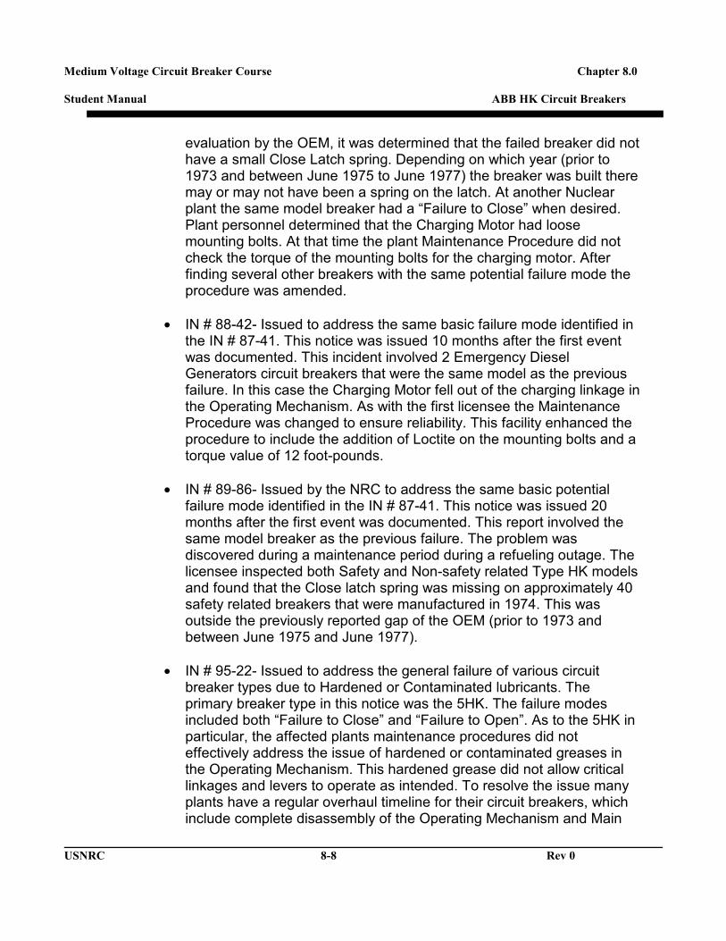
• Puffer nozzle- on a 5HK breaker the puffer is part of the moving contact assembly with an individual puffer for each phase (Figure 8-3). The 7.5 HK and above has a single puffer assembly which directs air into individual nozzles located under the stationary contacts (Figure 8-2)
Medium Voltage Circuit Breaker Course Chapter 8.0 Student Manual ABB HK Circuit Breakers
USNRC 8-4 Rev 0
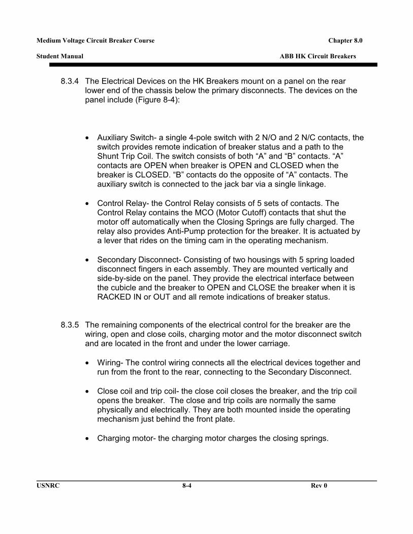
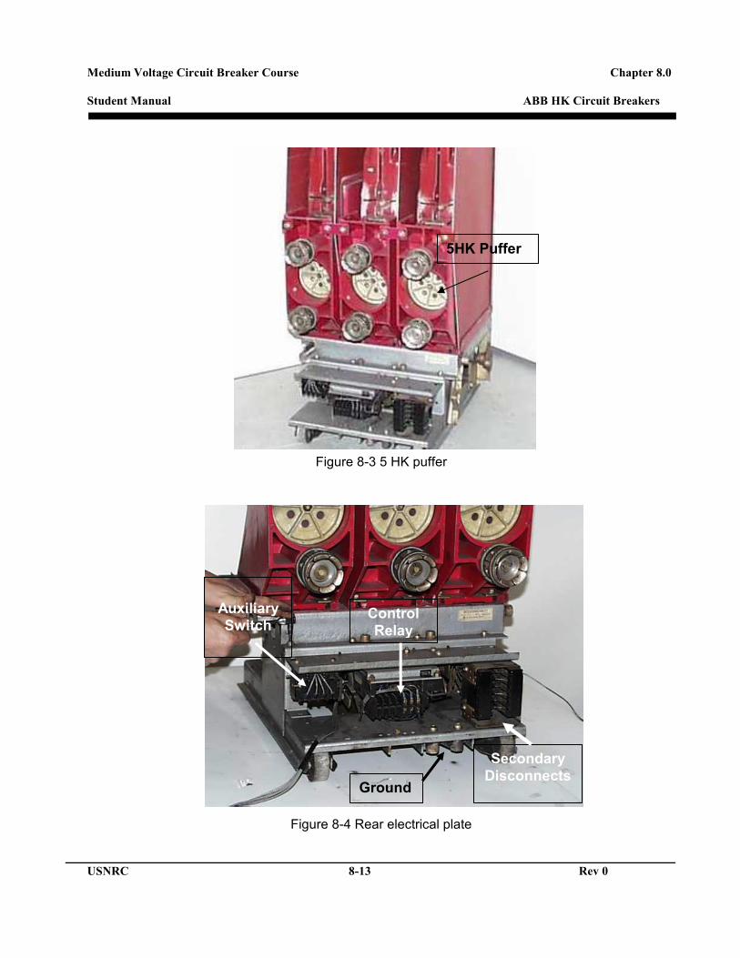
8.3.4 The Electrical Devices on the HK Breakers mount on a panel on the rear lower end of the chassis below the primary disconnects. The devices on the panel include (Figure 8-4):
• Auxiliary Switch- a single 4-pole switch with 2 N/O and 2 N/C contacts, the
switch provides remote indication of breaker status and a path to the Shunt Trip Coil. The switch consists of both “A” and “B” contacts. “A” contacts are OPEN when breaker is OPEN and CLOSED when the breaker is CLOSED. “B” contacts do the opposite of “A” contacts. The auxiliary switch is connected to the jack bar via a single linkage.
• Control Relay- the Control Relay consists of 5 sets of contacts. The Control Relay contains the MCO (Motor Cutoff) contacts that shut the motor off automatically when the Closing Springs are fully charged. The relay also provides Anti-Pump protection for the breaker. It is actuated by a lever that rides on the timing cam in the operating mechanism.
• Secondary Disconnect- Consisting of two housings with 5 spring loaded disconnect fingers in each assembly. They are mounted vertically and side-by-side on the panel. They provide the electrical interface between the cubicle and the breaker to OPEN and CLOSE the breaker when it is RACKED IN or OUT and all remote indications of breaker status.
8.3.5 The remaining components of the electrical control for the breaker are the wiring, open and close coils, charging motor and the motor disconnect switch and are located in the front and under the lower carriage. • Wiring- The control wiring connects all the electrical devices together and
run from the front to the rear, connecting to the Secondary Disconnect.
• Close coil and trip coil- the close coil closes the breaker, and the trip coil opens the breaker. The close and trip coils are normally the same physically and electrically. They are both mounted inside the operating mechanism just behind the front plate.
• Charging motor- the charging motor charges the closing springs.

Medium Voltage Circuit Breaker Course Chapter 8.0 Student Manual ABB HK Circuit Breakers
USNRC 8-5 Rev 0
The motor mounts on the operating mechanism on left side and is connected to a drive lever connected to a charging pawl, which drives the charging ratchet.
• Motor Disconnect Switch- Manual Toggle switch that opens the circuit to the
Charging Motor when desired. Mounted just in front of the motor on the left side of the operating mechanism.
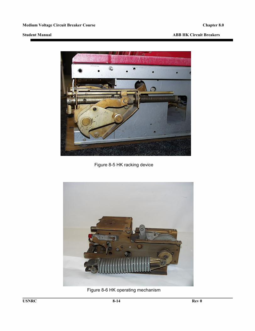
8.3.6 The Racking Device mounts on lower right side of the breaker and has a pivot
shaft that runs the length of the breaker, left to right (Figure 8-5). Racking operation and safety Interlocks.
• Racking Interlock- A mechanical interlock prevents a CLOSED breaker from
being RACKED IN or RACKED OUT. The handle will not move unless breaker is OPEN.
• When the breaker is OPEN the racking handle can be moved to the left, allowing the racking screw to be turned CW to rack a breaker in and CCW to rack the breaker out.
• The racking interlock also keeps the HK breaker from closing unless it is one of three keyed positions.
o CONNECT position: is when the breaker is fully RACKED IN.
The Primary disconnects are firmly seated on the bus and the Secondary Disconnects are fully engaged. Moving the handle and turning the racking screw CCW, when the handle resets again the breaker is in the TEST position.
o TEST position: is when the primary disconnects are not touching the bus and the shutter is down and the secondary disconnect is partially engaged, allowing electrical operation of the breaker. Moving the handle and turning the racking screw CCW, when the handle is resets again the breaker is in the DISCONNECT position.
o DISCONNECT position: is when the Primary disconnects are not touching the bus and the shutter is down. The Secondary disconnects are not engaged and the breaker is held captive in the cubicle. Moving the handle a last time and turning CCW, the breaker is moved to the REMOVE position.
o REMOVED position: is when the breaker can be rolled out of the cubicle for servicing. If the handle is left in this position the breaker cannot close as it puts the mechanism in a tripped position.

Medium Voltage Circuit Breaker Course Chapter 8.0 Student Manual ABB HK Circuit Breakers
USNRC 8-6 Rev 0
8.3.7 Chassis mounted components: other components on the chassis are: • Jack bar: common shaft which connects the mechanism and the
connecting links • The Main contact opening springs: are completely contained inside the
breaker chassis. o For the 5HK there are two springs that mount vertically on the left and
right side of the breaker. They attach to each end of the jack bar via a “J” hook.
o For the 7.5HK and above the opening springs are located above the operating mechanism towards the front of the breaker.
• Rejection Bracket- Located under the chassis on the rear, directly below
the control panel, the bracket keeps breakers of dissimilar ratings from being RACKED IN to the wrong cubicle.
• The MOC switch actuator mounts on the lower left side of the chassis and is connected to the jack bar. The MOC Switch actuator actuates the MOC (Mechanically Operated Contact) switch located in the breaker cubicle providing remote indication that the breaker is OPEN or CLOSED.
• The Shutter Roller mounts on the left rear side of the chassis, just above the MOC switch actuator and engages a ramp in the cubicle as the breaker is RACKED IN, lifting the shutter covering the busywork where the breaker Primary Disconnects engage
• Ground contact: Located on bottom rear of the breaker grounds the breaker when connected to the bus (Figure 8-4).
8.3.8 HK operating mechanism (Figure 8-6): All the HK operating mechanisms
used at nuclear plants are essentially the same. The closing springs will change as the breaker rating increases. The mechanism contains all the mechanical latches, toggle assemblies, cams, rollers, levers and linkages required to OPEN and CLOSE the breaker. The Operating Mechanism connects to the jack bar directly with a single linkage and pivot pin.

Medium Voltage Circuit Breaker Course Chapter 8.0 Student Manual ABB HK Circuit Breakers
USNRC 8-7 Rev 0
8.4 COMMON FAILURE MODES FOR THE HK BREAKER
Historically, there have been some issues with the HK breaker in the nuclear industry over the years. There have been several NRC bulletins and Information Notices issued for this breaker model since the mid 1980’s.
8.4.1 NRC bulletins and Information Notices
• IN # 83-50 Issued by the NRC to address the issue of Failures to Close on demand on Class 1E Circuit breakers. Although not specifically noted in this Information Notice the HK breaker could display the same failure modes. This notice is a result of a study by the NRC over a 5-year period and over 100 licensee events on 1E Class breakers. The study concluded that the failures were attributed to the failed breakers closing circuitry in the breakers cubicle. Most commonly, blown control fuses, electrical connections or dirty contacts, etc. The failures were common for a certain breaker type, which indicates that the corrective actions did not solve the problem. The results of this study by the NRC were improvements in surveillance of the breakers, maintenance procedures and Operations training.
• IN # 84-46- Issued by the NRC to address the “Failure to Close” on demand of a 5HK breaker. In this incident, the failed breaker was RACKED OUT to isolate a pump circuit for testing. When the test was complete the breaker was RACKED IN and the Control Room had a confirmed that the breaker was ready to operate due an indicator light on the control board. When the Operator attempted to close the breaker a week later, the breaker failed to close. It was found that the Racking Interlock kept the breaker in a “TRIP FREE” state since it was between TESTS and CONNECT positions. Due to this failure it was determined that 4 conditions must be met to ensure operability of the breaker. First, visual confirmation of breaker status by markings on the breaker and cubicle floor are lined up that show breaker is RACKED IN, that the Racking lever is fully in the CONNECT position, that the racking lever is in the fully CCW position, that the motor disconnect toggle switch is in the ON position, and the control fuses are in place and power is available.
• IN # 87-41- Issued due to the general failure of certain HK breakers at separate Nuclear Power plants. At one facility the breaker closed unexpectedly when it was RACKED IN to the CONNECT position. Upon
Medium Voltage Circuit Breaker Course Chapter 8.0 Student Manual ABB HK Circuit Breakers
USNRC 8-8 Rev 0
evaluation by the OEM, it was determined that the failed breaker did not have a small Close Latch spring. Depending on which year (prior to 1973 and between June 1975 to June 1977) the breaker was built there may or may not have been a spring on the latch. At another Nuclear plant the same model breaker had a “Failure to Close” when desired. Plant personnel determined that the Charging Motor had loose mounting bolts. At that time the plant Maintenance Procedure did not check the torque of the mounting bolts for the charging motor. After finding several other breakers with the same potential failure mode the procedure was amended.
• IN # 88-42- Issued to address the same basic failure mode identified in
the IN # 87-41. This notice was issued 10 months after the first event was documented. This incident involved 2 Emergency Diesel Generators circuit breakers that were the same model as the previous failure. In this case the Charging Motor fell out of the charging linkage in the Operating Mechanism. As with the first licensee the Maintenance Procedure was changed to ensure reliability. This facility enhanced the procedure to include the addition of Loctite on the mounting bolts and a torque value of 12 foot-pounds.
• IN # 89-86- Issued by the NRC to address the same basic potential failure mode identified in the IN # 87-41. This notice was issued 20 months after the first event was documented. This report involved the same model breaker as the previous failure. The problem was discovered during a maintenance period during a refueling outage. The licensee inspected both Safety and Non-safety related Type HK models and found that the Close latch spring was missing on approximately 40 safety related breakers that were manufactured in 1974. This was outside the previously reported gap of the OEM (prior to 1973 and between June 1975 and June 1977).
• IN # 95-22- Issued to address the general failure of various circuit breaker types due to Hardened or Contaminated lubricants. The primary breaker type in this notice was the 5HK. The failure modes included both “Failure to Close” and “Failure to Open”. As to the 5HK in particular, the affected plants maintenance procedures did not effectively address the issue of hardened or contaminated greases in the Operating Mechanism. This hardened grease did not allow critical linkages and levers to operate as intended. To resolve the issue many plants have a regular overhaul timeline for their circuit breakers, which include complete disassembly of the Operating Mechanism and Main

Medium Voltage Circuit Breaker Course Chapter 8.0 Student Manual ABB HK Circuit Breakers
USNRC 8-9 Rev 0
Contacts.
• One of the most common failures for the 5HK breakers is the electrical control device such as the Control Device, Motor Disconnect switches, and Auxiliary switches.
8.4.2 Other breaker material issues.
A The Control device is subject to high contact resistance and physical damage to the device itself. The Control device housing can crack and the actuator arm will bend. The Motor disconnect switch has a small set of contacts that corrode over time and the Secondary Disconnects can be damaged due to handling or misalignment. The Auxiliary switch can have the contacts wear down increasing the resistance of the switch and the housing can crack over time. The Stationary Intermediate/Arcing Contacts also wear over time due to the number of cycles. Hardened grease can lead to other failures such as burnt Trip coils and wiring.
8.5 MAINTENANCE SCHEDULING FOR THE HK BREAKER
Regular Maintenance is the key to reliability for the 5HK Circuit breakers and all other breaker types. All Nuclear Power plants have an Approved Maintenance Procedure for their circuit breakers. These procedures are usually based on the OEM Technical Manual for a specific breaker type. A good PM procedure will change to include additional steps as the plant personnel find problems while performing the PM. It would also include updated SAL’s or equipment upgrades.
In most cases the OEM will recommend how often the PM cycle should be, but environment role in determining the PM frequency as does the number of operations.
The original tech manual OEM recommended maintenance and schedule for the 5HK breaker is outlines below:
Type 5HK75, 5HK150, 5HK250- 2000 operations (No load or load current switching)
• Remove covers • Wipe down insulators • Clean off the Arc Chutes • Check Main Contact wipe • Ductor Main Contacts

Medium Voltage Circuit Breaker Course Chapter 8.0 Student Manual ABB HK Circuit Breakers
USNRC 8-10 Rev 0
• Timing Test 5HK350- 1000 operations (No load or load current switching) • Remove covers • Wipe down insulators • Clean off the Arc Chutes • Check Main Contact wipe • Ductor Main Contacts • Timing Test Type 5HK75, 5HK150, 5HK250- 1000 operations (Motor starting or reactor switching) • Remove covers • Wipe down insulators • Clean off the Arc Chutes • Check Main Contact wipe • Ductor Main Contacts • Timing Test
5HK350- 500 operations (Motor starting or reactor switching) • Remove covers • Wipe down insulators • Clean off the Arc Chutes • Check Main Contact wipe • Ductor Main Contacts • Timing Test
8.6 ADJUSTMENTS
The Main contact wipe is the only major adjustment required for the HK breaker. There are some minor control component adjustments.
8.7 SUBCOMPONENT REPLACEMENT FOR THE HK BREAKER
During the PM cycle it is possible that some parts on the breaker will be found to be broken, bent, burnt, cracked or worn out. Replacement parts for most HK breakers are readily available and are well supported by the OEM.
While the OEM Technical manual for the 5HK does not provide step-by-step instructions for replacing component parts, most major parts are accessible.

Medium Voltage Circuit Breaker Course Chapter 8.0 Student Manual ABB HK Circuit Breakers
USNRC 8-11 Rev 0
8.8 DESIGN UPGRADES FOR THE HK BREAKER
The replacement parts for the 5HK have not changed significantly since the original design. There have been minor changes to the Control Device contacts and the charging motor design has been changed in non-safety related applications. A return springs has been added for the close latch.
8.9 LUBRICATION TYPE FOR THE HK BREAKER
There are different types of recommended Lubricants for the HK breaker. Depending on the location of a particular component or sub-assembly would dictate what type of lubricant is required. It is always prudent to not mix and match different lubricants together. The most common lubricant in non-current carrying parts is Anderol 757. Some Nuclear Power plants have been using Mobil Red 28 in non-current carrying parts but only if ALL traces of Anderol 757 have been removed. For the contacts and all main current carrying parts of the 5HK the lubricant is NO-OX-ID.
8.10 ROUTINE MAINTENANCE FOR THE HK BREAKER
It has already been established the importance of routine maintenance. It is important to have only properly trained and qualified personnel work on the HK breakers. Although these breakers can take a lot of abuse many of the problems were identified after an overhaul or maintenance cycle. During this training seminar, the objective is to utilize the PM Manual for the HK breaker to help in understanding the function of the breaker.

Medium Voltage Circuit Breaker Course Chapter 8.0 Student Manual ABB HK Circuit Breakers
USNRC 8-12 Rev 0
Figure 8-1 HK contact assemblies
Figure 8-2 HK main contacts
Phase Insulator
“BUTT” Style Contacts
7.5HK Puffer nozzle
Medium Voltage Circuit Breaker Course Chapter 8.0 Student Manual ABB HK Circuit Breakers
USNRC 8-13 Rev 0
Figure 8-3 5 HK puffer
Figure 8-3 5 HK puffer
Figure 8-4 Rear electrical plate
5HK Puffer
Auxiliary Switch
Control Relay
Secondary Disconnects
Ground
Medium Voltage Circuit Breaker Course Chapter 8.0 Student Manual ABB HK Circuit Breakers
USNRC 8-14 Rev 0
Figure 8-5 HK racking device
Figure 8-6 HK operating mechanism