Media Access Control Layer Proposal for the 802.16.1 Air Interface
257
Project IEEE 802.16 Broadband Wireless Access Working Group Title Media Access Control Layer Proposal for the 802.16.1 Air Interface Specification Date Submitted 2000-07-07 Source Glen Sater Motorola Inc. 8220 E. Roosevelt Street, M/D R1106 Scottsdale, AZ 85257 Ken Stanwood Ensemble Communications Inc. 9890 Town Centre Dr. San Diego, CA 92121 Voice: 480-441-8893 Fax: 480-675-2116 E-mail: [email protected] Voice: 858-404-6544 Fax: 858-458-1401 E-mail: [email protected] Additional Contirbutions Arun Arunachalam, George Stamatelos Jeff Foerster Scott Marin, Bill Myers Leland Langston, Wayne Hunter Phil Guillemette Chet Shirali, Menashe Shahar Karl Stambaugh George Fishel Ray Sanders Moshe Ran Andrew Sundelin Yonatan Manor Brian Petry, Mark Vogel James Mollenauer Carl Eklund, Juha Pihlaja, Kari Rintanen Doug Gray Paolo Baldo Paul Kennard Andrea Nascimbene Naftali Chayat, Leonid Shousterman, Vladimir Yanover Demosthenes Kostas Jay Klein Company Nortel Networks Alcatel SpectraPoint Wireless, LLC. Crosspan, a Raytheon Telecommunications Company SpaceBridge Networks Corporation Vyyo Inc. Motorola, Inc. Communications Consulting Services CircuitPath Networks Systems TelesciCOM, Ltd. iSKY Oren Semiconductors 3Com Technical Strategy Associates Nokia Lucent Technologies Siemens Digital Microwave Ericsson BreezeCOM Adaptive Broadband Ensemble Communications Re: 802.16.1 INVITATION TO CONTRIBUTE: Session #8, Document 80216-00_13r1 Abstract This is a joint proposal that merges two contributions presented to the Working Group during Session #7 (documents IEEE 802.16.1mc-00/14 and IEEE 802.16.1mc-00/15). The process of combining the two documents was guided by the outline of agreements developed in Session #7.5, which amended the call for contributions for session #8. The proposed MAC provides connection-oriented links between the Base Station and CPEs. Each connection is associated with peer convergence sub-processes and service flows. Higher-layer infor- mation is tunneled through the MAC using the QoS provided by the serivce flows. In this manner, the MAC can be extended to support a wide variety of bearer transport and signaling mechanisms without modification to the core MAC services. The MAC fully supports the merged PHY layer as defined in 802.16.1pc-00/29r1. Purpose To provide a detailed description of a proposed MAC layer specification for IEEE 802.16 WG. Notice This document has been prepared to assist IEEE 802.16. It is offered as a basis for discussion and is not binding on the contributing individual(s) or organization(s). The material in this document is sub- ject to change in form and content after further study. The contributor(s) reserve(s) the right to add, amend or withdraw material contained herein. IEEE 802.16.1mc-00/21r1
Transcript of Media Access Control Layer Proposal for the 802.16.1 Air Interface

IEEE 802.16.1mc-00/21r1
Project IEEE 802.16 Broadband Wireless Access Working Group
Title Media Access Control Layer Proposal for the 802.16.1 Air Interface Specification
DateSubmitted
2000-07-07
Source Glen SaterMotorola Inc.8220 E. Roosevelt Street, M/D R1106 Scottsdale, AZ 85257
Ken StanwoodEnsemble Communications Inc.9890 Town Centre Dr.San Diego, CA 92121
Voice: 480-441-8893Fax: 480-675-2116E-mail: [email protected]
Voice: 858-404-6544Fax: 858-458-1401E-mail: [email protected]
Additional ContirbutionsArun Arunachalam, George StamatelosJeff FoersterScott Marin, Bill MyersLeland Langston, Wayne HunterPhil GuillemetteChet Shirali, Menashe ShaharKarl StambaughGeorge FishelRay SandersMoshe RanAndrew SundelinYonatan ManorBrian Petry, Mark VogelJames MollenauerCarl Eklund, Juha Pihlaja, Kari RintanenDoug GrayPaolo BaldoPaul KennardAndrea NascimbeneNaftali Chayat, Leonid Shousterman, Vladimir YanoverDemosthenes KostasJay Klein
CompanyNortel NetworksAlcatelSpectraPoint Wireless, LLC.Crosspan, a Raytheon Telecommunications CompanySpaceBridge Networks CorporationVyyo Inc.Motorola, Inc.Communications Consulting ServicesCircuitPath Networks SystemsTelesciCOM, Ltd.iSKYOren Semiconductors3ComTechnical Strategy AssociatesNokiaLucent TechnologiesSiemensDigital MicrowaveEricssonBreezeCOM
Adaptive BroadbandEnsemble Communications
Re: 802.16.1 INVITATION TO CONTRIBUTE: Session #8, Document 80216-00_13r1
Abstract This is a joint proposal that merges two contributions presented to the Working Group during Session #7 (documents IEEE 802.16.1mc-00/14 and IEEE 802.16.1mc-00/15). The process of combining the two documents was guided by the outline of agreements developed in Session #7.5, which amended the call for contributions for session #8.
The proposed MAC provides connection-oriented links between the Base Station and CPEs. Each connection is associated with peer convergence sub-processes and service flows. Higher-layer infor-mation is tunneled through the MAC using the QoS provided by the serivce flows. In this manner, the MAC can be extended to support a wide variety of bearer transport and signaling mechanisms without modification to the core MAC services. The MAC fully supports the merged PHY layer as defined in 802.16.1pc-00/29r1.
Purpose To provide a detailed description of a proposed MAC layer specification for IEEE 802.16 WG.
Notice This document has been prepared to assist IEEE 802.16. It is offered as a basis for discussion and is not binding on the contributing individual(s) or organization(s). The material in this document is sub-ject to change in form and content after further study. The contributor(s) reserve(s) the right to add, amend or withdraw material contained herein.

IEEE 802.16.1mc-00/21r1
ion tent
ple-
rd is ood
been
Release The contributor grants a free, irrevocable license to the IEEE to incorporate text contained in this contribution, and any modifications thereof, in the creation of an IEEE Standards publication; to copyright in the IEEE’s name any IEEE Standards publication even though it may include portions of this contribution; and at the IEEE’s sole discretion to permit others to reproduce in whole or in part the resulting IEEE Standards publication. The contributor also acknowledges and accepts that this contribution may be made public by IEEE 802.16.
Portions of this document are reprinted with permission from Cable Television Laboratories, Inc.
IEEE Patent Policy
The contributor is familiar with the IEEE 802.16 Patent Policy and Procedures (Version 0.9) <http://ieee802.org/16/ipr/patents/policy.html>, including the statement “IEEE standards may include the known use of patent(s), including patent applications, if there is technical justification in the opinof the standards-developing committee and provided the IEEE receives assurance from the paholder that it will license applicants under reasonable terms and conditions for the purpose of immenting the standard.”Early disclosure to the Working Group of patent information that might be relevant to the standaessential to reduce the possibility for delays in the development process and increase the likelihthat the draft publication will be approved for publication. Please notify the Chair <mailto:[email protected]> as early as possible, in written or electronic form, of any patents (granted or under application) that may cover technology that is under consideration by or has approved by IEEE 802.16. The Chair will disclose this notification via the IEEE 802.16 web site<http://ieee802.org/16/ipr/patents/letters.html>.
2

IEEE 802.16.1mc-00/21r1
.... 52
...... 53.... 54..... 55.. 57...... 59....... 60.... 61..... 63...... 64.... 64..... 66.... 67.......... 69..... 71..... 71..... 73...... 74....
..... 78
..... 81
..... 83
1. Overview.............................................................................................................................................. 7
1.1 Scope............................................................................................................................................ 71.2 Purpose......................................................................................................................................... 7
2. Normative References.......................................................................................................................... 9
3. Definitions ......................................................................................................................................... 11
4. Acronyms and abbreviations ............................................................................................................. 13
5. MAC Service Definition.................................................................................................................... 17
6. Media Access Control........................................................................................................................ 19
6.1 Connections and Service Flows................................................................................................. 196.1.1 Addressing and Connection Identifiers.......................................................................... 20
6.2 Message Formats ....................................................................................................................... 236.2.1 Convergence Sub-layer PDU Formats........................................................................... 286.2.2 MAC Management Messages........................................................................................ 286.2.3 Downlink MAP (DL-MAP) Message............................................................................ 356.2.4 Uplink MAP (UL-MAP) Message................................................................................. 386.2.5 Ranging Request (RNG-REQ) Message........................................................................ 416.2.6 Ranging Response (RNG-RSP) Message ...................................................................... 436.2.7 Registration Request (REG-REQ) Message .................................................................. 486.2.8 Registration Response (REG-RSP) Message ................................................................ 496.2.9 Registration Acknowledge (REG-ACK) Message ........................................................ 516.2.10 Privacy Key Management — Request (PKM-REQ) Message ..................................6.2.11 Privacy Key Management — Response (PKM-RSP) Message...............................6.2.12 Dynamic Service Addition — Request (DSA-REQ) Message..................................6.2.13 Dynamic Service Addition — Response (DSA-RSP) Message ...............................6.2.14 Dynamic Service Addition — Acknowledge (DSA-ACK) Message..........................6.2.15 Dynamic Service Change — Request (DSC-REQ) Message..................................6.2.16 Dynamic Service Change — Response (DSC-RSP) Message ...............................6.2.17 Dynamic Service Change — Acknowledge (DSC-ACK) Message ..........................6.2.18 Dynamic Service Deletion — Request (DSD-REQ) Message .................................6.2.19 Dynamic Service Deletion — Request (DSD-RSP) Message .................................6.2.20 Multicast Polling Assignment Request (MCA-REQ) Message.................................6.2.21 Multicast Polling Assignment Response (MCA-RSP) Message ..............................6.2.22 Downlink Modulation Change Request (DMC-REQ) Message................................
6.3 Framing and Scheduling Intervals ........................................................................................ 696.3.1 PHY Burst Mode Support.........................................................................................6.3.2 PHY Continuous Mode Support ...............................................................................6.3.3 Downlink Burst Subframe Structure.........................................................................6.3.4 Uplink Burst Subframe Structure .............................................................................6.3.5 Continuous Downstream and Upstream Structure...................................................6.3.6 Upstream Map............................................................................................................ 756.3.7 Requests ......................................................................................................................... 786.3.8 MAP Relevance and Synchronization ......................................................................
6.4 Contention Resolution ............................................................................................................... 806.4.1 Transmit Opportunities .............................................................................................
6.5 Fragmentation ............................................................................................................................ 816.6 Upstream Service....................................................................................................................... 82
6.6.1 Unsolicited Grant Service.........................................................................................
3

IEEE 802.16.1mc-00/21r1
6.6.2 Real-Time Polling Service............................................................................................. 836.6.3 Unsolicited Grant Service with Activity Detection ....................................................... 836.6.4 Non-Real-Time Polling Service..................................................................................... 846.6.5 Best Effort Service......................................................................................................... 84
6.7 Bandwidth Allocation and Request Mechanisms ...................................................................... 856.7.1 Polling............................................................................................................................ 856.7.2 Poll-Me Bit .................................................................................................................... 89
6.8 Network Entry and Initialization ............................................................................................... 896.8.1 Scanning and Synchronization to Downstream ............................................................. 916.8.2 Obtain Downstream Parameters .................................................................................... 926.8.3 Obtain Upstream Parameters ......................................................................................... 926.8.4 message Flows During Scanning and Upstream Parameter Acquisition....................... 946.8.5 Initial Ranging and Automatic Adjustments ................................................................. 956.8.6 Ranging Parameter Adjustment ................................................................................... 1006.8.7 Initial Connection Establishment................................................................................. 1006.8.8 Transfer Operational Parameters ................................................................................. 101
6.9 Ranging.................................................................................................................................... 1076.9.1 Downstream Modulation Management ....................................................................... 109
6.10 Quality of Service .................................................................................................................... 1136.10.1 Theory of Operation..................................................................................................... 1136.10.2 Service Flows............................................................................................................... 1136.10.3 Object Model ............................................................................................................... 1166.10.4 Service Classes ............................................................................................................ 1176.10.5 Authorization ............................................................................................................... 1186.10.6 Types of Service Flows................................................................................................ 1196.10.7 General Operation........................................................................................................ 1206.10.8 Dynamic Service.......................................................................................................... 124
6.11 Parameters and Constants ........................................................................................................ 1656.12 Encodings for Configuration and MAC-Layer Messaging...................................................... 167
6.12.1 Configuration File and Registration Settings............................................................... 1676.12.2 Configuration-File-Specific Settings ........................................................................... 1716.12.3 Registration-Request/Response-Specific Encodings................................................... 1736.12.4 Dynamic-Service-Message-Specific Encodings.......................................................... 1756.12.5 Quality-of-Service-Related Encodings ........................................................................ 1766.12.6 Privacy Configuration Settings Option........................................................................ 1876.12.7 Confirmation Code ...................................................................................................... 1876.12.8 Convergence Sub-Layer Parameter Encodings ........................................................... 188
6.13 Configuration File.................................................................................................................... 1886.13.1 CPE IP Addressing ...................................................................................................... 1886.13.2 CPE Configuration....................................................................................................... 1896.13.3 Configuration Verification........................................................................................... 192
7. Authentication and Privacy.............................................................................................................. 195
7.1 Privacy Plus Overview............................................................................................................. 1957.1.1 Architectural Overview................................................................................................ 1957.1.2 Operational Overview.................................................................................................. 197
7.2 MAC Frame Formats ............................................................................................................... 1987.2.1 Fragmentation and Encryption..................................................................................... 199
7.3 Privacy Key Management (PKM) Protocol............................................................................. 1997.3.1 State Models ................................................................................................................ 1997.3.2 Key Management Message Formats............................................................................ 217
7.4 Dynamic SA Mapping ............................................................................................................. 2487.4.1 Introduction.................................................................................................................. 248
4

IEEE 802.16.1mc-00/21r1
7.5 Key Usage................................................................................................................................ 2487.5.1 BS................................................................................................................................. 2487.5.2 CPE .............................................................................................................................. 250
7.6 Cryptographic Methods ........................................................................................................... 2507.6.1 Packet Data Encryption ............................................................................................... 2507.6.2 Encryption of TEK....................................................................................................... 2517.6.3 HMAC-Digest Algorithm............................................................................................ 2517.6.4 Derivation of TEKs, KEKs and Message Authentication Keys .................................. 2517.6.5 Public-Key Encryption of Authorization Key ............................................................. 2527.6.6 Digital Signatures ........................................................................................................ 2527.6.7 Supporting Alternative Algorithms ............................................................................. 253
7.7 TFTP Configuration File Extensions ....................................................................................... 2537.7.1 Privacy Configuration Setting Encodings.................................................................... 253
5

IEEE 802.16.1mc-00/21r1
6

1. Overview
1.1 Scope
The scope of this standard is to develop a medium access control (MAC) and physical layer (PHY) specifi-cation for wireless connectivity for broadband wireless access systems.
1.2 Purpose
<TBD>.
7

IEEE 802.16.1mc-00/21r1
8

IEEE 802.16.1mc-00/21r1
1750,
on”,
mber
and
wood
wood
ber
2. Normative References
This standard shall be used in conjunction with the following publications.
[FIPS-46-2]Federal Information Processing Standard Publications 46-2, Data Encryption Standard (DES),December 30, 1993.
[FIPS-74]Federal Information Processing Standards Publication (FIPS PUB) 74, Guidelines for Implement-ing and Using the Data Encryption Standard, April 1981.
[FIPS-81]Federal Information Processing Standards Publication (FIPS PUB) 81, DES Modes of Operation,December 1980.
[FIPS-140-1]Federal Information Processing Standards Publication (FIPS PUB) 140-1, Security Require-ments for Cryptographic Modules, April 1982.
[FIPS-180-1]Federal Information Processing Standards Publication (FIPS PUB) 180-1, Secure Hash Stan-dard, April 1995.
[FIPS-186]Federal Information Processing Standards Publication (FIPS PUB) 186, Digital Signature Stan-dard, 18 May 1994.
[IEEE1]IEEE Std 802-1990, IEEE Standards for Local and Metropolitan Area Net-works:Overview andArchitecture, December 1990.
[RFC1750]D. Eastlake, S. Crocker, J. Schiller, “Randomness Recommendations for Security”, RFCDecember 1994.
[RFC2104]H. Krawczyk, M. Bellare, R. Canetti, “HMAC: Keyed-Hashing for Message AuthenticatiRFC 2104, February 1997.
[RFC2202]P. Cheng, R. Glenn, “Test cases for HMAC-MD5 and HMAC-SHA-1”, RFC2202, Septe1997.
[RFC2459]R. Housley, W. Ford, W. Polk, D. Solo, “Internet X.509 Public Key Infrastructure CertificateCRL Profile”, RFC2459, January 1999.
[RSA]RSA Laboratories, “The Public-Key Cryptography Standards”, RSA Data Security, Inc., RedCity, CA.
[RSA1]RSA Laboratories, “PKCS #1: RSA Encryption Standard. Version 1.5”, November 1993.
[RSA2]RSA Laboratories, “Some Examples of the PKCS Standards,” RSA Data Security, Inc., RedCity, CA, November 1, 1993.
[RSA3]RSA Laboratories, “PKCS #1 v2.0: RSA Cryptography Standard”, Octo
9

IEEE 802.16.1mc-00/21r1
10

IEEE 802.16.1mc-00/21r1
3. Definitions
3.1 Base Station (BS): A generalized equipment set providing connectivity, management, and control of theCPE.
3.2 Burst Profile: Set of parameters that describe the upstream transmission properties that are associatedwith an IUC. Each profile contains parameters such as modulation type, preamble length, guard times, etc.
3.3 Connection: A unidirectional mapping between equivalent BS and CPE peers. Connections are identi-fied by a CID. All traffic is carried on a connection.
3.4 Connection Identifier (CID): A unidirectional, MAC-layer address that identifies a connection toequivalent peers in the CPE and BS MAC. A CID maps to a SFID, which defines the QoS parameters to theService Flow associated with that connection. Security associations also exist be keying material and CIDs.
3.5 Customer Premises Equipment (CPE): A generalized equipment set providing connectivity betweensubscriber equipment and a BS.
3.6 Downlink: A flow of information that exists in the downstream.
3.7 Downstream: The direction from a BS to the CPE.
3.8 Frame: A frame is a fixed duration of time, which contains both transmit and receive intervals.
3.9 Information Element (IE): A component of the UL-MAP that defines the length and address assign-ment associated with an IUC. Taken as a whole, each IE represents a type of upstream transmission. Mulit-ple IEs may exist in the UL-MAP.
3.10 Interval Usage Code (IUC): Defines the type of usage of an Information Element. IUCs are definedfor bandwidth requests, data grants, etc.
3.11 Grant Per Connection (GPC): A bandwidth allocation method in which grants are aggregated for allconnections and are allocated to the CPE terminal as that aggregate. Note that bandwidth requests arealways made for a connection.
3.12 Grant Per Terminal (GPT): A bandwidth allocation method in which grants are allocated to a connec-tions within a CPE. Note that bandwidth requests are always made for a connection.
3.13 Mini-slot: A unit of bandwidth allocation equivalent to N PS, where N = 2m (m = 0,...7).
3.14 Multicast Group: Agroup of zero or more CPEs or connections that are assigned a mulitcast addressfor the purposes of polling.
3.15 Physical-Slot (PS): A unit of granularity equal to 4 modulation symbols. Each PS represents 8, 16, or24 bits (using QAM-4, QAM-16, or QAM-64 modulation, respectively).
3.16 Privacy Key Management Protocol (PKM): A client/server model between the BS and CPE that isused to secure distribution of keying material.
3.17 Security Association (SA): The set of security information a BS and one or more of its client CPEshare in order to support secure communications across the BWA network.
3.18 Service Flow: A Service Flow is a unidirectional flow of PDUs on a connection that is provided a par-ticular Quality of Service.
11

IEEE 802.16.1mc-00/21r1
3.19 Service Flow Class: A grouping of Service Flow properties to allow higher layer entities and externalapplications to request Service Flows with desired QoS parameters in a globally consistent way.
3.20 Service Flow Name: An ASCII string that is used to reference a set of QoS parameters that (partially)define a Service Flow.
3.21 Uplink: A flow of information that exists in the upstream.
3.22 Uplink MAP (UL-MAP): A set of information that defines the entire access for a scheduling interval.
3.23 Upstream: The direction from a CPE to the BS.
12

IEEE 802.16.1mc-00/21r1
4. Acronyms and abbreviations
ATDD Adaptive Time Division DuplexingBR Bandwidth RequestBS Base StationCG Continuous GrantCID Connection IdentifierCPE Customer Premises EquipmentCS Convergence SubprocessCSI Convergence Subprocess IndicatorCTG CPE Transition GapDAMA Demand Assign Multiple AccessDES Data Encryption StandardDL Down LinkDSA Dynamic Service AdditionDSC Dynamic Service ChangeDSD Dynamic Service DeletionEC Encryption ControlEKS Encryption Key SequenceFC Fragment ControlFDD Frequency Division DuplexFSN Fragment Sequence NumberGM Grant ManagementGPC Grant Per ConnectionGPT Grant Per TerminalHCS Header Check SequenceH-FDD Half-duplex FDDHL-MAA High Level Media Access ArbitrationHT Header TypeIE Information ElementIUC Interval Usage CodeLL-MAA Low Level Media Access ArbitrationMAC Medium Access ControlMIC Message Integrity CheckMTG Modulation Transition GapPCD Physical Channel DescriptorPBR Piggy-Back RequestPDU Protocol Data UnitPHY Physical layerPI PHY Information elementPKM Privacy Key ManagementPM Poll Me bitPS Physical SlotQoS Quality of ServiceRS Reed-SolomonSAP Service Access PointSI Slip IndicatorSDU Service Data UnitTC Transmission ConvergenceTDD Time Division DuplexTDM Time Division MultiplexTDMA Time Division Multiple AccessTDU TC Data UnitTLV Type-Length-Value
13

IEEE 802.16.1mc-00/21r1
TRGT Tx/Rx Transmission GapUGS Unsolicited Grant ServiceUGS-AD Unsolicited Grant Service with Activity DetectionUL Up Link
14

IEEE 802.16.1mc-00/21r1
15

IEEE 802.16.1mc-00/21r1
16

IEEE 802.16.1mc-00/21r1
5. MAC Service Definition
<TBD>.
17

IEEE 802.16.1mc-00/21r1
18

IEEE 802.16.1mc-00/21r1
6. Media Access Control
In a network that utilizes a shared medium, there must be a mechanism to provide an efficient way to sharethe medium. A two-way point-to-multipoint wireless network is a good example of a shared medium: herethe medium is the space through which the radio waves propagate.
The downlink, from the base station to the user operates on a point-to-multipoint basis. The 802.16.1 wire-less link operates with a central base station and a sectorized antenna which is capable of handling multipleindependent sectors simultaneously. Within a given frequency channel and antenna sector, all stationsreceive the same transmission. The base station is the only transmitter operating in this direction, hence itcan transmit without having to coordinate with other stations, except for the overall time-division duplexingthat divides time into upstream and downstream transmission periods. It broadcasts to all stations in the sec-tor (and frequency); stations check the address in the received messages and retain only those addressed tothem.
However, the user stations share the upstream period on a demand basis. Depending on the class of serviceutilized, the CPE may be issued continuing rights to transmit, or the right to transmit may be granted by thebase station after receipt of a request from the user.
In addition to individually-addressed messages, messages may also be sent to multicast groups (controlmessages and video distribution are examples of multicast applications) as well as broadcast to all stations.
Within each sector, users must adhere to a transmission protocol which minimizes contention between usersand enables the service to be tailored to the delay and bandwidth requirements of each user application.
This is accomplished through five different types of upstream scheduling mechanism, which are imple-mented using unsolicitied bandwidth grants, polling, and contention procedures. Mechanisms are defined inthe protocol to allow vendors to optimize system performance using different combinations of these band-width allocation techniques while maintaining consistent inter-operability definitions. For example, conten-tion can be used to avoid the individual polling of CPEs which have been inactive for a long period of time.
The use of polling simplifies the access operation and guarantees that applications receive service on a deter-ministic basis if it is required. In general, data applications are delay tolerant, but real-time applications likevoice and video require service on a more uniform basis, and sometimes on a very tightly-controlled sched-ule.
6.1 Connections and Service Flows
The MAC is connection-oriented. For the purposes of mapping to services on CPEs and associating varyinglevels of QoS, all data communications are in the context of a connection. These connections are provi-sioned when a CPE is installed in the system, and set up over the air at CPE registration to provide a refer-ence against which to request bandwidth. Additionally, new connections may be established whencustomer’s service needs change. A connection defines both the mapping between peer convergence pro-cesses that utilize the MAC and a Service Flow. The Service Flow defines the QoS parameters for the PDUsthat are exchanged on the connection.
The concept of a Service Flow on a Connection is central to the operation of the MAC protocol. ServiceFlows provide a mechanism for upstream and downstream Quality of Service management. In particular,they are integral to the bandwidth allocation process. A CPE requests upstream bandwidth on a per-connec-tion basis (implicitly identifying the Service Flow). Bandwidth is granted by the BS either as an aggregate ofall grants for a CPE (within a scheduling interval) or on a connection basis.
19

IEEE 802.16.1mc-00/21r1
Once connections are established they must be maintained. The maintenance requirements vary dependingupon the type of service connected. For example, unchannelized T1 services require virtually no connectionmaintenance since they have a constant bandwidth allocated every frame. Channelized T1 services requiresome maintenance due to the dynamic (but relatively slowly changing) bandwidth requirements if com-pressed, coupled with the requirement that full bandwidth be available on demand. IP services may requirea substantial amount of ongoing maintenance due to their bursty nature and due to the high possibility offragmentation across frames. As with connection establishment, modifiable connections may require main-tenance due to stimulus from either the CPE or the network side of the connection.
Finally, connections may be terminated. This generally occurs only when a customer’s service contractchanges. The termination of a connection is stimulated by the BS or CPE.
All three of these connection management functions are supported throught the use of static configurationand dynamic addition, modification, and deletion of connections.
6.1.1 Addressing and Connection Identifiers
Each CPE shall maintain a 64-bit EUI for globally unique addressing purposes. This address uniquelydefines the CPE from within the set of all possible vendors and equipment types. This address is used duringthe registration process to establish the appropriate connections for a CPE. It is also used as part of theauthentication process by which the BS and CPE each verify the identity of each other.
Connections are identified by a 16-bit Connection Identifier. Every CPE must establish at least two connec-tions in each direction (upstream and downstream) to enable communication with the BS. The Basic Con-nection IDs, assigned to a CPE at registration, are used by the BS MAC and the CPE MAC to exchangeMAC control messages, provisioning and management information.
For bearer services, the higher layers of the BS set up connections based upon the provisioning informationdistributed to the base station. The registration of a CPE, or the modification of the services contracted at aCPE, stimulates the higher layers of the BS to initiate the setup of the connections.
The connection ID can be considered a connection identifier even for nominally connectionless traffic likeIP, since it serves as a pointer to destination and context information. The use of a 16-bit connection ID per-mits a total of 64K connections within the sector.
Requests for transmission are based on these connection IDs, since the allowable bandwidth may differ fordifferent connections, even within the same service type. For example, a CPE unit serving multiple tenantsin an office building would make requests on behalf of all of them, though the contractual service limits andother connection parameters may be different for each of them.
Many higher-layer sessions may operate over the same wireless connection ID. For example, many userswithin a company may be communicating with TCP/IP to different destinations, but since they all operatewithin the same overall service parameters, all of their traffic is pooled for request/grant purposes. Since theoriginal LAN source and destination addresses are encapsulated in the payload portion of the transmission,there is no problem in identifying different user sessions.
The type of service is implicit in the connection ID; it is accessed by a lookup indexed by the connection ID.
There are several CIDs defined in Table 1 that having specific meaning. These identifiers shall not be usedfor any other purposes.
20

IEEE 802.16.1mc-00/21r1
Table 1—Connection Identifiers
Connection Identifier Value Description
Initial Ranging 0x0000 Used by a CPE during initial ranging as part of network entry process.
Temporary Registration 0..m
Basic CIDs m..n
Transport CIDs n..0xFDFF
Priority Request CIDs 0xFEXX Request IE UsageIf 0x01 bit is set, priority zero can requestIf 0x02 bit is set, priority one can requestIf 0x04 bit is set, priority two can requestIf 0x08 bit is set, priority three can requestIf 0x10 bit is set, priority four can requestIf 0x20 bit is set, priority five can requestIf 0x40 bit is set, priority six can requestIf 0x80 bit is set, priority seven can request
Multicast Polling CIDs 0xFF00..0xFFFE A CPE may be included in one or more multicast groups for the purposes of obtaining bandwidth via polling. These connections have no associated Service Flow.
Broadcast CID 0xFFFF Used for broadcast information that is transmitted on a downlink to all CPE.
21

IEEE 802.16.1mc-00/21r1
22

IEEE 802.16.1mc-00/21r1
6.2 Message Formats
MAC Protocol Data Units (PDU) shall be of the form illustrated in Figure 1. Each PDU is preceeded by afixed-length generic MAC header. The PDU may contain optional payload information from a convergencesub-layer. The payload information can vary in length, so that a MAC PDU will represent a variable numberof bytes. The payload information is divided into a convergence sub-layer header and data portions. The def-inition and use of these message components is defined outside of the scope of the core MAC protocol. Thisallows the MAC to tunnel various higher layer traffic types without knowledge of the formats or bit patternsof those messages.
Messages are always transmitted in the order: Most-Significant-Byte first with the Most-Significant-Bit firstin each byte.
Three MAC header formats are defined. The first two are generic headers that precede each MAC Message,including both management and convergence sub-layer data. The third format is used to request additionalbandwidth. The single bit Header Type (HT) field distinguishes the generic and bandwidth request headerformats. The HT field shall be set to 0 for generic headers. The HT field shall be set to 1 for a bandwidthrequest header.
Figure 1—MAC PDU Formats
Convergence Sub-layer Data
Generic MAC Header Payload (optional)
ConvergenceSub-layerHeader
23

IEEE 802.16.1mc-00/21r1
The format shown in Figure 2 shall be used for all PDUs transmitted by the CPE to the BS in the uplinkdirection. For downlink transmissions, the format shown in Figure 3 shall be used.
These two generic header formats are equivalent with the exception of the Grant Mangament field, which isonly present in uplink transmissions.
HCS
Figure 2—Generic MAC Header Format (Uplink)
LengthEC EKS
Connection Identifier
GMHT FC FSN
Piggy-Back Request
Grants Per IntervalSI
SI PMUnsolicited Grant Service
Unsolicited Grant Servicewith Activity Detection
All others
Grant Management
CSI=0
Bit 0 8 15
HCS
Figure 3—Generic MAC Header Format (Downlink)
LengthEC EKS
Connection Identifier
HT FC FSNCSI=0
Bit 0 8 15
24

IEEE 802.16.1mc-00/21r1
The Grant Management field is one byte in length and is used by the CPE to convey bandwidth managementneeds to the BS. This field is encoded differently based upon the type of connection (as given by the Con-nection ID). The use of this field is defined in Section 6.7.
The third header is a special format used by a CPE to request additional bandwidth. This header shall alwaysbe transmitted without a PDU. The format of the Bandwidth Request Header is given in Figure 4.
The Bandwidth Request Header is used by a CPE to request uplink bandwidth. A Bandwidth RequestHeader shall not have an associated payload:
a) The length of the header shall always be 7 bytes,b) The EC field shall be set to 1, indicating no encryption,c) The CID shall indicate the Service Flow for which uplink bandwidth is requested,d) The Bandwidth Request (BR) field shall indicate the number of mini-slots requested.
A CPE receiving a Bandwidth Request Header on the downlink shall discard the PDU.
The various fields of the header formats are defined in Table 2. Every header is encoded starting with the ECand EKS fields. The coding of these fields is such that the first byte of a MAC header shall never have the
Figure 4—Bandwidth Request Header Format
Length (=7)
CID
HT BR
1
HCS
=1
0000
Bit 0 8 15
25

IEEE 802.16.1mc-00/21r1
value of 0xFX. This prevents false detection on the stuff byte used in the Transmission Convergence Sub-layer.
Table 2—MAC Header Fields
Name Length(bits) Description
BR 15 Bandwidth Request
The number of bytes of uplink bandwidth requested by the CPE. The bandwidth request is for the CID. The request shall not include any PHY layer overhead
CID 16 Connection Identifier
CSI 1 Convergence Sub-layer Indication
This bit is allocated to a convergence layer process for signaling between equivalent peers.
EC 1 Encryption Control
1 = Payload is not encrypted0 = Payload is encrypted
26

IEEE 802.16.1mc-00/21r1
Multiple MAC PDUs may be concatenated into a single transmission in either the uplink or downlink direc-tions. Figure 5 illustrates this concept for an uplink burst transmission. Since each PDU is identifiied by aunique Connection Identifier, the receiving MAC entity is able to present the PDU to the correct SAP based
EKS 4 Encryption Key Sequence
The index of the Traffic Encryption Key and Initialization Vector used to encrypt the pay-load. This field is only meaningful if the Encryption Control field is set to zero. This field must be set to all zeros when the EC is 1.
FC 2 Fragmentation Control
Indicates the fragmentation state of the payload:00 = no fragmentation01 = last fragment10 = first fragment11 = continuing (middle) fragment
FSN 4 Fragmentation Sequence Number
Defines the sequence number of the current fragment. The initial fragment (FC=10) sets this field to 0. This field increments by one (modulo 16) for each fragment.
When fragmentation is not used (FC= 00), this field shall be set to 0.
GPI 7 Grants Per Interval
The number of grants required by a connection using UGS with Activity Detection
HCS 8 Header Check Sequence
An 8-bit field used to detect errors in the header. The generator polynomial is g(D)=D8 + D2 + D + 1.
HT 1 Header Type
0 = Generic Header1 = Bandwidth Request Header
LEN 11 Length
The length in bytes of the entire MAC header and any MAC PDU information that follows this specific header.
PBR 8 Piggy-Back Request
The number of bytes of uplink bandwidth requested by the CPE. The bandwidth request is for the CID. The request shall not include any PHY layer overhead.
PM 1 Poll-Me
0 = No action.1 = Used by the CPE to request a bandwidth poll.
SI 1 Slip Indicator
0 = No action1 = Used by the CPE to indicate a slip of uplink grants relative to the uplink queue depth.
Table 2—MAC Header Fields
Name Length(bits) Description
27

IEEE 802.16.1mc-00/21r1
upon that Identifier. Management, user data, and bandwidth request PDUs may be concatenated into thesame tranmission.
6.2.1 Convergence Sub-layer PDU Formats
The format of the convergence sub-layer PDU shall be as shown in Figure 6. A Convergence Sub-layer PDUmay have a zero length payload.
6.2.2 MAC Management Messages
A set of management Messages are defined within the core MAC. These Messages shall use the standardMessage format as given in Section 6.2.1. All management Messages shall begin the payload content with a
Figure 5—MAC PDU Concatention
User Bandwidth ManagementPDURquest PDUPDU
UserPDU
UserPDU
Uplink Burst #n Uplink Burst #n+1
CID = 0x2301 CID = 0x0399 CID = 0x0EF1 CID = 0x5F3E CID = 0x2555
Figure 6—Convergence Sub-layer PDU Format
Convergence Sub-layer Payload
Generic Header
28

IEEE 802.16.1mc-00/21r1
single byte field indicating the management Message type. The format of the management Message is givenFigure 7. The encoding of the Message type field is given in Table 3.
Table 3—MAC Management Messages
Type Message Name Message Description
1 PCD Physical Channel Descriptor
2 DL-MAP Downlink Access Definition
3 UL-MAP Uplink Access Definition
4 RNG-REQ Ranging Request
5 RNG-RSP Ranging Response
6 REG-REQ Registration Request
7 REG-RSP Registration Response
8 REG-ACK Registration Acknowledge
9 PKM-REQ Privacy Key Management Request
10 PKM-RSP Privacy Key Management Response
11 DSA-REQ Dynamic Service Addition Request
12 DSA-RSP Dynamic Service Addition Response
13 DSA-ACK Dynamic Service Addition Acknowledge
14 DSC-REQ Dynamic Service Change Request
Figure 7—MAC Management Message Format
Management Message Type
Management Message Payload
Generic Header
Bit 0 8 15
29

IEEE 802.16.1mc-00/21r1
6.2.2.1 Physical Channel Descriptor (PCD) Message
An Physical Channel Descriptor shall be transmitted by the BS at a periodic interval to define the character-istics of an physical channel. A separate PCD Message shall be transmitted for each active uplink.
15 DSC-RSP Dynamic Service Change Response
16 DSC-ACK Dynamic Service Change Acknowledge
17 DSD-REQ Dynamic Service Deletion Request
18 DSD-RSP Dynamic Service Deletion Response
19 DCC-REQ Dynamic Channel Change Request
20 DCC-RSP Dynamic Channel Change Response
21 MCA-REQ Multicast Assignment Request
22 MCA-RSP Multicast Assignment Response
23 DMC-REQ Downlink Modulation Change Request
24-255 Reserved for future use
Table 3—MAC Management Messages
Type Message Name Message Description
30

IEEE 802.16.1mc-00/21r1
To provide for flexibility the message parameters following the channel ID shall be encoded in a type/length/value (TLV) form in which the type and length fields are each 1 octet long.
A BS shall generate PCDs in the format shown in Figure 8, including all of the following parameters:
Configuration Change Count
Incremented by one (modulo the field size) by the BS whenever any of the values of this channeldescriptor change. If the value of this count in a subsequent PCD remains the same, the CPE canquickly decide that the remaining fields have not changed, and may be able to disregard the remain-der of the message. This value is also referenced from the UL-MAP messages.
Mini-Slot Size
The size T of the Mini-Slot for this uplink channel in units of Physical Slots. Allowable values are T= 2m, where m = 0,...7.
Uplink Channel ID
The identifier of the uplink channel to which this Message refers. This identifier is arbitrarily chosenby the BS and is only unique within the MAC-Sublayer domain.
Downlink Channel ID
Figure 8—Physical Channel Descriptor (PCD) Message Format
MAC Management Header
Uplink
TLV Encoded information for the overall channel
Mini-slot
TLV-encoded Burst Description (#n)
Channel IDConfigurationChange Count Size
DownlinkChannel ID
TLV-encoded Burst Description (#1)
0 8 16 24 31
31

IEEE 802.16.1mc-00/21r1
The identifier of the downlink channel on which this Message has been transmitted. This identifier isarbitrarily chosen by the BS and is only unique within the MAC-Sublayer domain.
All other parameters are coded as TLV tuples. The type values used shall be those defined in Table 4, forchannel parameters, and Table 5, for uplink physical layer burst attributes. Channel-wide parameters (fromTable 4) shall preceed burst descriptors (type 1 below).
Burst Descriptors are compound TLV encodings that define, for each type of uplink usage interval, the phys-ical-layer characteristics that are to be used during that interval. The uplink interval usage codes are defined
Table 4—Physical Channel Attributes
Name Type(1 byte)
Length(1 byte)
Value(Variable Length)
Burst Descriptor 1 May appear more than once; described below. The length is the number of bytes in the overall object, including embedded TLV items.
Symbol Rate 2 2 5 - 40 MBaud. The incremental rates are not yet defined for the PHY layer. The use of a TLV allows future clarification of this field without modification to the MAC.
Frequency 3 4 Uplink center frequency (kHz)
Preamble Pattern 4 1-128 Preamble superstring. All burst-specific preamble values are cho-sen as bit-substrings of this string.
The first byte of the Value field contains the first 8 bits of the superstring, with the first bit of the preamble superstring in the MSB position of the first Value field byte, the eighth bit of the pre-amble superstring in the LSB position of the first Value field byte; the second byte in the Value field contains the second eight bits of the superstring, with the ninth bit of the superstring in the MSB of the second byte and sixteenth bit of the preamble superstring in the LSB of the second byte, and so forth.
Tx/Rx Gap 5 1 The number of PS between the end of the downlink and uplink transmissions. This TLV is only used if the PHY Type field of the DL-MAP message is {0, 1} (TDD).
Rx/Tx Gap 6 1 The number of PS between the end of the uplink and downlink transmissions. This TLV is only used if the PHY Type field of the DL-MAP message is {0, 1} (TDD).
Shortened Downlink CPE Preamble Length
7 1 TBD by the PHY Group.
BS Transmit Power 8 1 Signed in units of 1dB
MAC Version 9 1 Version number of the MAC supported on this channel.
32

IEEE 802.16.1mc-00/21r1
in the UL-MAP Message. illustrates the format of each Burst Descruption TLV. Each TLV is encoded with aType of 1, an eight bit length, and a four bit IUC.
A Burst Descriptor shall be included for each Interval Usage Code that is to be used in the UL-MAP. TheInterval Usage Code shall be one of the values from Table 6.
Figure 9—Top-Level Encoding for a Burst Descriptor
Type = 1 Length1..n
TLV codes for PHY parameters
(Burst Descriptor) IUC
33

IEEE 802.16.1mc-00/21r1
Within each Burst Descriptor is an unordered list of Physical-layer attributes, encoded as TLV values. Theseattributes are shown in Table 5.
Table 5—Uplink Physical Layer Burst Profile Parameters
Name Type(1 byte)
Length(1 byte)
Value(Variable Length)
Modula-tion Type
1 1 1 = QPSK, 2 = 16QAM, 3 = 64-QAM
Differen-tial Encod-ing
2 1 1 = on, 2 = off
Preamble Length
3 2 Up to 1024 bits. The value must be an integral number of symbols (a multiple of 2 for QPSK and 4 for 16QAM and 6 for 64QAM)
Preamble Value Off-set
4 2 Identifies the bits to be used for the preamble value. This is speci-fied as a starting offset into the Preamble Pattern (see Table 4). That is, a value of zero means that the first bit of the preamble for this burst type is the value of the first bit of the Preamble Pattern. A value of 100 means that the preamble is to use the 101st and suc-ceeding bits from the Preamble Pattern. This value must be a multi-ple of the symbol size.
The first bit of the Preamble Pattern is the firstbit transmitted in the uplink burst.
FEC Error Correction (T)
5 1 0-10 (0 implies no FEC. The number of codeword parity bytes is 2*T)
FEC Code-word Infor-mation Bytes (k)
6 1 Fixed: 16 to 253 (assuming FEC on)Shortened: 16 to 253 (assuming FEC on)(Not used if no FEC, T=0)
Scrambler Seed
7 2 The 15-bit seed value left justified in the 2 byte field. Bit 15 is the MSB of the first byte and the LSB of the second byte is not used. (Not used if scrambler is off)
Maximum Burst Size
8 1 The maximum number of bytes that can be transmitted during this burst type. Absence of this configuration setting implies that the burst size is limited elsewhere. When the interval type is Short Data Grant this value shall be present and greater than zero.
Guard Time Size
9 1 Number of symbol times which must follow the end of this burst. (Although this value may be derivable from other network and architectural parameters, it is included here to ensure that the CPEs and BS all use the same value.)
Last Code-word Length
10 1 1 = fixed; 2 = shortened
Scrambler on/off
11 1 1 = on; 2 = off
34

IEEE 802.16.1mc-00/21r1
6.2.3 Downlink MAP (DL-MAP) Message
The Downlink MAP (DL-MAP) message defines the access to the downlink information relative to the PHYmode. The DL-MAP message takes on different formats depending upon the value of the PHY Type field.
A BS shall generate DL-MAP messages in the format shown in Figure 10, including all of the followingparameters:
PHY Synchronization
A four byte field. The first three bits define the PHY type, as given by the following value:0 = TDD1 = FDD/TDM (Burst Downlink PHY)3 = FDD/TDMA5 = FDD/TDM (Continuous Downlink PHY)
The remaining 29 bits are encoded as shown in Figure 11 for PHY Type = {0..2} or Figure 12 forPHY Type = 3. For burst downlink PHY operations, the bits are encoded as the frame number. Forcontinuous downlink PHY operations, the bits are encoded as a timestamp that synchronizes theuplink transmissions.
The encoding of remaining portions of the DL-MAP message are also based upon the PHY field.For PHY Type = 3, no additional information follows the Base Station ID field. For PHY Type = {0,1}, a set of mapping information sorted by modulation type is defined as in Figure 13. For PHYType = 2, a set of mapping information sorted by Connection ID is defined as in Figure 14.
Figure 10—Downlink MAP Message Format (PHY Type = 4)
MAC Management Header
Base Station ID[0:31]
PHY Synchronization
Base Station ID[32:63]
MAP Elements (PHY Type = {0..3})
35

IEEE 802.16.1mc-00/21r1
Figure 11—PHY Synchronization Field (PHY Type = {0..3})
PHY Type Hyperframe Number[14..7]
Hyperframe Number[6:0]MultiframeNumber
FrameNumber
Figure 12—PHY Synchronization Field (PHY Type = 1)
PHY Type Uplink Timestamp[29:16]
Uplink Timestamp[15:0]
Figure 13—Downlink TDM MAP Message Element Format
QAM-16 Physical Slot Start
Downlink MAP Message
QAM-64 Physical Slot Start
End Physical Slot
36

IEEE 802.16.1mc-00/21r1
The CID entry in the TDMA version of the DL-MAP message defines the allocation of bandwidth for thatconnection. For a CPE operating in GPC mode, the CID shall be the Transport CID. For a CPE operating inGPT mode, the CID shall be the Basic CID.
Figure 14—Downlink TDMA MAP Message Element Format
Physical Slot Start
Downlink MAP Message
Physical Slot Start
Connection Identifier
Connection Identifier
Connection Identifier Physical Slot Start
37

IEEE 802.16.1mc-00/21r1
6.2.4 Uplink MAP (UL-MAP) Message
The Uplink MAP (UL-MAP) message allocates access to the upstream channel. The UL-MAP messageshall be as shown in .Figure 16
Uplink Channel ID
Figure 15—Uplink MAP Message Format
PCD Channel ID PCD Count Number of Elements
Allocation Start Time
Acknowledgement Time
Ranging BackoffStart
Ranging BackoffEnd
Data BackoffStart
Data BackoffEnd
IUC OffsetConnection ID
IUC Offset = 0Connection ID
IUC=7 Offset = map lengthConnection ID = 0
IUC Offset = map lengthConnection ID(data grant pending)
IUC Offset = map lengthConnection ID(data grant pending)
MAC Management Header
0 8 16 24 31
38

IEEE 802.16.1mc-00/21r1
The identifier of the uplink channel to which this Message refers.
PCD Count
Matches the value of the Configuration Change Count of the PCD which describes the burst param-eters which apply to this map.
Number Elements
Number of information elements in the map.
Alloc Start Time
Effective start time of the uplink allocation defined by the UL-MAP in units of mini-slots. The starttime is relative to the start of a frame in which UL-MAP message is transmitted (PHY Type ={0..2}) or from BS initialization (PHY Type = 3).
Ack Time
Latest time processed in uplink in units of mini-slots. This time is used by the CPE for collisiondetection purposes. The ack time is relative to the start of a frame in which UL-MAP message istransmitted (PHY Type = {0..2}) or from BS initialization (PHY Type = 3).
Ranging Backoff Start
Initial back-off window size for initial ranging contention, expressed as a power of 2. Values of nrange 0-15 (the highest order bits must be unused and set to 0).
Ranging Backoff End
Final back-off window size for initial ranging contention, expressed as a power of 2. Values of nrange 0-15 (the highest order bits must be unused and set to 0).
Data Backoff Start
Initial back-off window size for contention data and requests, expressed as a power of 2. Values of nrange 0-15 (the highest order bits must be unused and set to 0).
Data Backoff End
Final back-off window size for contention data and requests, expressed as a power of 2. Values of nrange 0-15 (the highest order bits must be unused and set to 0).
MAP Information Elements
Information elements define uplink bandwidth allocations. Each UL-MAP message shall contain atleast one Information Element. The format of the IE shall be as shown in Figure 16. Each IE consistsof three fields: a Connection Identifer, an Interval Usage Code, and an offset.
The Connection Identifier represent the assignment of the IE to either a unicast, multicast, or broad-cast address. When specifically addressed to allocate a bandwidth grant, the CID may be either theBasic CID of the CPE or a Traffic CID for one of the connections of the CPE. A four-bit IntervalUsage Code (IUC) shall be used to define the type of uplink access and the burst type associatedwith that access. Table 6 defines the use of the IUCs. The offset shall be the length from the start ofthe previous IE to the start of this IE in units of mini-slots. The first IE shall have an offset of 0.
39

IEEE 802.16.1mc-00/21r1
Three pairs of data grant Information Elements are defined. This allows each pair to be assigned to a differ-ent burst profile pair, typically based upon modulation type. For example, the first pair would be assigned touse QPSK, the second pair would use 16-QAM, and the third would use 64-QAM. Within each pair, theshort and long grant usage is distinguished by the maximum burst size. This allows short PDU transmissionsfor services that are tolerant of packet loss to use less FEC coding (relative to longer grants).
Table 6—Uplink MAP Information Elements
IE Name
IntervalUsageCode(IUC)
Connection ID Mini-slot Offset
Request 1 any Starting offset of REQ region
InitialMaintenance
2 broadcast Starting offset of MAINT region (used in Initial Ranging)
Figure 16—UL-MAP Information Element
Interval
Connection Identifier
Offset
Bit 0 8 15
Usage Code
40

IEEE 802.16.1mc-00/21r1
6.2.5 Ranging Request (RNG-REQ) Message
A Ranging Request shall be transmitted by a CPE at initialization and periodically on request from BS todetermine network delay and request power and/or modulation adjustment. This shall be followed by aPacket PDU in the format shown in Figure 17.
StationMaintenance
3 unicast Starting offset of MAINT region (used in Periodic Ranging)
Short Data Grant
4 unicast Starting offset of Data Grant assignmentIf inferred length = 0, then it is a Data Grant pending.
Long Data Grant
5 unicast Starting offset of Data Grant assignmentIf inferred length = 0, then it is a Data Grant Pending
Short Data Grant 2
6 unicast Starting offset of Data Grant 2 assignmentIf inferred length = 0, then it is a Data Grant pending.
Long Data Grant 2
7 unicast Starting offset of Data Grant 2 assignmentIf inferred length = 0, then it is a Data Grant pending.
Short Data Grant 3
8 unicast Starting offset of Data Grant 3 assignmentIf inferred length = 0, then it is a Data Grant pending.
Long Data Grant 3
9 unicast Starting offset of Data Grant 3 assignmentIf inferred length = 0, then it is a Data Grant pending.
Null IE 10 zero Ending offset of the previous grant.Used to bound the length of the last actual interval allocation.
Reserved 11-14 any Reserved
Expansion 15 expanded IUC # of additional 32-bit words in this IE
Table 6—Uplink MAP Information Elements
IE Name
IntervalUsageCode(IUC)
Connection ID Mini-slot Offset
41

IEEE 802.16.1mc-00/21r1
The RNG-REQ Message shall be transmitted using QPSK modulation.
Parameters shall be as follows:
CID (from the MAC Management Header)
For RNG-REQ Messages transmitted in Initial Maintenance intervals:a) Initialization CID if modem is attempting to join the networkb) Initialization CID if modem has not yet registered and is changing downlink (or both downlink and
uplink) channels as directed by a downloaded parameter filec) Temporary CID if modem has not yet registered and is changing uplink (not downlink) channels as
directed by a downloaded parameter filed) Registration CID (previously assigned in REG-RSP) if modem is registered and is changing uplink
channels
For RNG-REQ Messages transmitted in Station Maintenance intervals:Basic CID
Downlink Channel ID
The identifier of the downlink channel on which the BS received the PCD which described thisuplink. This is an 8-bit field.
Pending Till Complete
If zero, then all previous Ranging Response attributes have been applied prior to transmittting thisrequest. If nonzero then this is time estimated to be needed to complete assimilation of rangingparameters. Note that only equalization can be deferred. Units are in unsigned centiseconds (10msec).
Figure 17—RNG-REQ Message Format
Downlink Pending TilChannel ID Complete
TLV Encoded Information
MAC Management Header
42

IEEE 802.16.1mc-00/21r1
All other parameters are coded as TLV tuples.
Modulation Type
An optional parameter. The Modulation type requested by the BS for downlink traffic. The BS deter-mines the appropriate modulation type to use based upon measurements of the downlink RF channelrelative to the Modulation Transition Thresholds defined in the RNG-RSP Message.
CPE MAC Address (EUI-64 Bit)
A required parameter. The MAC address of the CPE.
6.2.5.1 RNG-REQ TLV Encodings
The type values used shall be those defined in Table 7. These are unique within the ranging request Messagebut not across the entire MAC Message set. The type and length fields shall each be 1 octet in length.
6.2.6 Ranging Response (RNG-RSP) Message
A Ranging Response shall be transmitted by a BS in response to received RNG-REQ. It may be noted that,from the point of view of the CPE, reception of a Ranging Response is stateless. In particular, the CPE shallbe prepared to receive a Ranging Response at any time, not just following a Ranging Request.
The RNG-RSP Message shall be transmitted using QPSK modulation.
To provide for flexibility, the Message parameters following the Uplink Channel ID shall be encoded in atype/length/value (TLV) form.
Table 7—Ranging Request Message Encodings
Name Type(1 byte)
Length(1 byte)
Value(Variable Length)
ModulationType
1 1 1 = QPSK, 2 = 16-QAM, 3 = 64-QAM
CPE MACAddress
2 8 CPE MAC Address in EUI-64 format
Reserved 3-255 n Reserved for future use
43

IEEE 802.16.1mc-00/21r1
A BS shall generate Ranging Responses in the form shown in Figure 18, including all of the followingparameters:
Uplink Channel ID
The identifier of the uplink channel on which the BS received the RNG-REQ to which this responserefers.
All other parameters are coded as TLV tuples.
Timing Adjust Information
The time by which to offset frame transmission so that frames arrive at the expected mini-slot timeat the BS.
Power Adjust Information
Specifies the relative change in transmission power level that the CPE is to make in order that trans-missions arrive at the BS at the desired power.
Frequency Adjust Information
Specifies the relative change in transmission frequency that the CPE is to make in order to bettermatch the BS. (This is fine-frequency adjustment within a channel, not re-assignment to a differentchannel)
CPE Transmitter Equalization Information
This provides the equalization coefficients for the pre-equalizer.
Figure 18—RNG-RSP Message Format
TLV Encoded Information
MAC Management Header
UplinkChannel ID
44

IEEE 802.16.1mc-00/21r1
Ranging Status
Used to indicate whether uplink Messages are received within acceptable limits by BS.
Downlink Frequency Override
An optional parameter. The downlink frequency with which the modem should redo initial ranging.
Uplink Channel ID Override
An optional parameter. The identifier of the uplink channel with which the modem should redo ini-tial ranging.
16-QAM Threshold
An optional parameter. The threshold for transition between QPSK and 16-QAM on a downlinkchannel is specified by the BS for use by the CPE.
64-QAM Threshold
An optional parameter. The threshold for transition between 16-QAM and 64-QAM on a downlinkchannel is specified by the BS for use by the CPE.
Threshold Delta
An optional parameter. The delta about which a hysteresis is defined for transition of the CPEbetween modulation types. Used by the CPE in conjuction with the 16-QAM and 64-QAM Thresh-olds to determine when to request a modulation change for the downlink channel.
Modulation Type
An optional parameter. The maximum allow set of Modulation types allowed for the CPE for down-link traffic. This parameter is sent in response to the RNG-REQ Modulation Type from the CPE.The CPE responds with the maximum allowed set of modulation types based upon the combinationof the requested modulation type and the maximum allowable modulation type determined at regis-tration or from a dynamic service operation.
CID
If the modem is being instructed by this response to move to a different channel, this is initialization-CID. If the corresponding RNG-REQ was an initial ranging request specifying a initialization CID,then this is the assigned temporary CID.
Note that in all other cases, the CID is encoded in the MAC Management Header is not sent as aTLV.
CPE MAC Address (EUI-64 Bit)
A required parameter. The MAC address of the CPE.
45

IEEE 802.16.1mc-00/21r1
6.2.6.1 RNG-RSP TLV Encodings
The type values used shall be those defined in Table 8 and Figure 21. These are unique within the rangingresponse Message but not across the entire MAC Message set. The type and length fields shall each be 1octet in length.
Table 8—Ranging Response Message Encodings
Name Type(1 byte)
Length(1 byte)
Value(Variable Length)
Timing Adjust
1 4 Tx timing offset adjustment (signed 32-bit, units of ¼ symbols)
Power Level Adjust
2 1 Tx Power offset adjustment (signed 8-bit, ¼-dB units)
Offset Fre-quency Adjust
3 4 Tx frequency offset adjustment (signed 32-bit, Hz units)
Transmit Equaliza-tion Adjust
4 n Tx equalization data - see details below
Ranging Status
5 1 1 = continue, 2 = abort, 3 = success
Downlink frequency override
6 4 Center frequency of new downlink channel in kHz
Uplink channel ID override
7 1 Identifier of the new uplink channel.
16-QAM Threshold
8 1 C/I+N for minimum 16-QAM operation in ¼ dB.
64-QAM Threshold
9 1 C/I+N for minimum 64-QAM operation in ¼5 dB.
Threshold Delta
10 1 Hysteresis delta for modulation threholds in ¼ dB.
Modula-tion Type
11 1 1 = QPSK, 2 = QPSK or 16-QAM, 3 = QPSK or 16/64-QAM
CPE MACAddress
12 8 CPE MAC Address in EUI-64 format
Reserved 13-255 n Reserved for future use
46

IEEE 802.16.1mc-00/21r1
linearefficient
nts maye second
The number of forward taps per symbol shall be in the range of 1 to 4. The main tap location refers to theposition of the zero delay tap, between 1 and N. For a symbol-spaced equalizer, the number of forward tapsper symbol field shall be set to “1”. The number of reverse taps (M) field shall be set to “0” for a equalizer. The total number of taps may range up to 64. Each tap consists of a real and imaginary coentry in the table.
If more than 255 bytes are needed to represent equalization information, then several type-4 elemebe used. Data shall be treated as if byte-concatenated, that is, the first byte after the length field of thtype-4 element is treated as if it immediately followed the last byte of the first type-4 element.
Figure 19—Generalized Decision Feedback Equalization Coefficients
last coefficient FN (imag)
first reverse coefficient D1(imag)
last reverse coefficient DM(imag)
last coefficient FN (real)
first reverse coefficient D1(real)
last reverse coefficient DM(real)
type4
length number of forwardtaps per symbol
number offorward taps (N)
number ofreverse taps (M)
main taplocation
first coefficient F1 (real) first coefficient F1 (imag)
Figure 20—Generalized Equalizer Tap Location Definition
F3
D5
F4
D4
F5
D3
F6
D2
F2
D6
F1
DM
Z-T
Z-R
FN
D1
EqualizerInput
EqualizerOutput
Z-R Z-R Z-R Z-R Z-R
Z-T Z-T Z-T Z-T Z-T Z-T
R = T, T/2, T/4
47

IEEE 802.16.1mc-00/21r1
6.2.7 Registration Request (REG-REQ) Message
A Registration Request shall be transmitted by a CPE at initializatioollowing the CID shall be encoded in atype/length/value form. A CPE shall generate Registration Requests in the form shown in Figure 21
CID (from the MAC Management Header)
Temporary CID for this CPE.
All other parameters are coded as TLV tuples as defined in Section 6.12.
Registration Requests can contain many different TLV parameters, some of which are set by the CPEaccording to its configuration file and some of which are generated by the CPE itself. If found in the Config-uration File, the following Configuration Settings shall be included in the Registration Request.
Configuration File Settings:
— Downlink Frequency Configuration Setting— Uplink Channel ID Configuration Setting— Network access Control Object— Uplink Service Flow Configuration Setting— Downlink Service Flow Configuration Setting— Privacy Configuration Setting— Maximum Number of Subscribers— Privacy Enable Configuration Setting— TFTP Server Timestamp— TFTP Server Provisioned Modem address— Downlink Modulation Configuration Setting— Vendor-Specific Information Configuration Setting— CPE MIC Configuration Setting— BS MIC Configuration Setting
The CPE shall forward the vendor specific configuration settings to the BS in the same order in which they werereceived in the configuration file to allow the Message integrity check to be performed.
The following registration parameter shall be included in the Registration Request.
Figure 21—REG-REQ Message Format
TLV Encoded Information
MAC Management Header
48

IEEE 802.16.1mc-00/21r1
a TLV
lowing
Vendor Specific Parameter:
— Vendor ID Configuration Setting (Vendor ID of CPE)
The following registration parameter shall also be included in the Registration Request.
— Modem Capabilities Encodings
The following registration parameter may also be included in the Registration Request.
— Modem IP address
The following Configuration Settings shall not be forwarded to the BS in the Registration Request.
— Software Upgrade Filename — Software Upgrade TFTP Server IP address— SNMP Write-access Control— SNMP MIB Object— CPE EUI-64 MAC address— HMAC Digest— End Configuration Setting— Pad Configuration Setting
6.2.8 Registration Response (REG-RSP) Message
A Registration Response shall be transmitted by BS in response to received REG-REQ.
To provide for flexibility, the Message parameters following the Response field shall be encoded in format.
A BS shall generate Registration Responses in the form shown in Figure 22, including both of the folparameters:
Figure 22—REG-RSP Message Format
TLV Encoded Information
Response
MAC Management Header
49

IEEE 802.16.1mc-00/21r1
CID (in the MAC Management Header) from Corresponding REG-REQ
CID from corresponding REG-REQ to which this response refers. (This acts as a transaction identi-fier)
Response
0 = Okay1 = Authentication Failure2 = Class of Service Failure
Note: Failures apply to the entire Registration Request. Even if only a single requested Service Flow is invalid orundeliverable the entire registration is failed.
If the REG-REQ was successful and contained Service Flow Parameters, the REG-RSP shall contain:
Service Flow Parameters
All the Service Flow Parameters from the REG-REQ, plus the Connection ID assigned by the BS.Every Service Flow that contained a Service Class Name that was admitted/activated shall beexpanded into the full set of TLVs defining the Service Flow. Every uplink Service Flow that wasadmitted/activated1 shall have a Connection Identifier assigned by the BS. A Service Flow that wasonly provisioned will include only those QoS parameters that appeared in the REG-REQ, plus theassigned Service Flow ID.
If the REG-REQ failed and contained Service Flow Parameters, the REG-RSP shall contain the following:
Service Flow Error Set
A Service Flow Error Set and identifying Service Flow Reference shall be included for every failedService Flow in the corresponding REG-REQ. Every Service Flow Error Set shall include everyspecific failed QoS Parameter of the corresponding Service Flow.
Service Class Name expansion always occurs at admission time. Thus, if a Registration-Request contains aService Flow Reference and a Service Class Name for deferred admission/activation, the Registration-Response shall not include any additional QoS Parameters except the Service Flow Identifier.
All other parameters are coded as TLV tuples:
CID #2
CID for secondary management purposes
Modem Capabilities
The BS response to the capabilities of the modem (if present in the Registration Request)
Vendor-Specific Data
As defined in Section 6.12— Vendor ID Configuration Setting (vendor ID of BS)— Vendor-specific extensions
1The ActiveQoSParamSet or AdmittedQoSParamSet is non-null.
50

IEEE 802.16.1mc-00/21r1
hand-
BS. ItG-RSP.
action
Note: The temporary CID shall no longer be used once the REG-RSP is received.
6.2.8.1 Encodings
The type values used shall be those shown below. These are unique within the Registration Response Mes-sage but not across the entire MAC Message set. The type and length fields shall each be 1 octet.
Modem Capabilities
This field defines the BS response to the modem capability field in the Registration Request. The BSresponds to the modem capabilities to indicate whether they may be used. If the BS does not recog-nize a modem capability, it must return this as “off” in the Registration Response.
Only capabilities set to “on” in the REG-REQ may be set “on” in the REG-RSP as this is the shake indicating that they have been successfully negotiated.
Encodings are as defined for the Registration Request.
6.2.9 Registration Acknowledge (REG-ACK) Message
A Registration Acknowledge shall be transmitted by the CPE in response to a REG-RSP from theconfirms acceptance by the CPE of the QoS parameters of the flow as reported by the BS in it REThe format of a REG-ACK shall be as shown in Figure 23.
The parameter shall be as follows:
CID (in the MAC Management Header) from Corresponding REG-RSP
CID from corresponding REG-RSP to which this acknowledgment refers. (This acts as a transidentifier)
Confirmation Code
Figure 23—REG-ACK Message Format
TLV Encoded Information
ConfirmationCode
MAC Management Header
51
IEEE 802.16.1mc-00/21r1
The appropriate Confirmation Code (refer to Section 6.12) for the entire corresponding RegistrationResponse.
The CPE shall forward all provisioned Service Flows to the BS. Since any of these provisioned items canfail, the REG-ACK shall include Error Sets for all failures related to these provisioned items.
Service Flow Error Set
The Service Flow Error Set of the REG-ACK Message encodes specifics of any failed ServiceFlows in the REG-RSP Message. A Service Flow Error Set and identifying Service Flow Referenceshall be included for every failed QoS Parameter of every failed Service Flow in the correspondingREG-RSP Message. This parameter shall be omitted if the entire REG-REQ/RSP is successful.
Note: Per Service Flow acknowledgment is necessary not just for synchronization between the CPE and BS, but also tosupport use of the Service Class Name. Since the CPE may not know all of the Service Flow parameters associated witha Service Class Name when making the Registration Request, it may be necessary for the CPE to NAK a RegistrationResponse if it has insufficient resources to actually support this Service Flow.
6.2.10 Privacy Key Management — Request (PKM-REQ) Message
Privacy Key Management protocol Messages transmitted from the CPE to the BS shall use the form shownin Figure 24.
Parameters shall be as follows:
PKM Code
The Code field is one octect and identifies the type of PKM packet. When a packet is recieved withan invalid Code field, it shall be silently discarded. The Code values are defined in Section 7.3.2.1.
PKM Identifier
Figure 24—PKM-REQ Message Format
TLV Encoded Information
LengthPKM Code PKM Identifier
MAC Management Header
52

IEEE 802.16.1mc-00/21r1
CPE’s
r fieldt, Keyt event.
ffectessagentifierKM shall
lar stateation, Key case
may not
ilentlynding
ilently pend-
ngthength
Lengthth is
The Identifier field is one octect. A CPE uses the identifier to match a BS response to the requests.
The CPE shall change (e.g., increment, wrapping around to 0 after reaching 255) the Identifiewhenever it issues a new PKM Message. A "new" Message is an Authorization RequesRequest or SA Map Request that is not a retransmission being sent in response to a TimeouFor retransmissions, the Identifier field shall remain unchanged.
The Identifier field in Authentication Information Messages, which are informative and do not eany response messaging, may be set to zero. The Identifier field in a BS’s PKM response Mshall match the Identifier field of the PKM Request Message the BS is responding to. The Idefield in Traffic Encryption Key (TEK) Invalid Messages, which are not sent in response to BPrequests, shall be set to zero. The Identifier field in unsolicited Authorization Invalid Messagesbe set to zero.
On reception of a BPKM response Message, the CPE associates the Message with a particumachine (the Authorization state machine in the case of Authorization Replies, AuthorizRejects, and Authorization Invalids; a particular TEK state machine in the case of Key RepliesRejects and TEK Invalids; a particular Security Association (SA) Mapping state machine in theof SA Map Replies and SA Map Rejects).
A CPE may keep track of the Identifier of its latest, pending Authorization Request. The CPEsilently discard Authorization Replies and Authorization Rejects whose Identifier fields domatch those of the pending requests.
A CPE may keep track of the Identifier of its latest, pending Key Request. The CPE may sdiscard Key Replies and Key Rejects whose Identifier fields do not match those of the perequests.
A CPE may keep track of the Identifier of its latest, pending SA Map Request. The CPE may sdiscard SA Map Replies and SA Map Rejects whose Identifier fields do not match those of theing requests.
Length
The Length field is two octets. It indicates the length of the Attribute fields in octets. The lefield does not include the Code, Identifier and Length fields. Octets outside the range of the Lfield shall be treated as padding and ignored on reception. If the packet is shorter than the field indicates, it should be silently discarded. The minimum length is 0 and maximum leng<TBD>.
All other parameters are encoded as TLV tuples as defined in Section 6.12.
6.2.11 Privacy Key Management — Response (PKM-RSP) Message
Privacy Key Management protocol Messages transmitted from the BS to the CPE shall use the form shownin Figure 25.
53

IEEE 802.16.1mc-00/21r1
6.2.12 Dynamic Service Addition — Request (DSA-REQ) Message
A Dynamic Service Addition Request may be sent by a CPE or BS to create a new Service Flow.
Figure 25—PKM-RSP Message Format
TLV Encoded Information
LengthPKM Code PKM Identifier
MAC Management Header
Figure 26—DSA-REQ Message Format
Transaction ID
TLV Encoded Information
MAC Management Header
54

IEEE 802.16.1mc-00/21r1
MAC-efer
DSA-spect to
f some,
denti-
ted with
A CPE or BS shall generate DSA-REQ Messages in the form shown in Figure 26 including the followingparameter:
Transaction ID
Unique identifier for this transaction assigned by the sender.
All other parameters are coded as TLV tuples as defined in Section 6.12. A DSA-REQ Message shall notcontain parameters for more than one Service Flow in each direction, i.e., a DSA-REQ Message shall con-tain parameters for either a single uplink Service Flow, or for a single downlink Service Flow, or for oneuplink and one downlink Service Flow.
The DSA-REQ Message shall contain:
Service Flow Parameters
Specification of the Service Flow’s traffic characteristics and scheduling requirements.
If Privacy is enabled, the DSA-REQ Message shall contain:
HMAC-Digest
The HMAC-Digest Attribute is a keyed Message digest (to authenticate the sender). The HDigest Attribute shall be the final Attribute in the Dynamic Service Message’s Attribute list. (Rto Section 6.12.4.1)
6.2.12.1 CPE-Initiated Dynamic Service Addition
Values of the Service Flow Reference are local to the DSA Message; each Service Flow within theRequest shall be assigned a unique Service Flow Reference. This value need not be unique with rethe other service flows known by the sender.
CPE-initiated DSA-Requests may use the Service Class Name (refer to Section 6.12.5.3.4) in place oor all, of the QoS Parameters.
6.2.12.2 BS-Initiated Dynamic Service Addition
BS-initiated DSA-Requests for Uplink Service Flows shall also include a Connection ID. Connection Ifiers are unique within the MAC domain.
BS-initiated DSA-Requests for named Service Classes shall include the QoS Parameter Set associathat Service Class.
6.2.13 Dynamic Service Addition — Response (DSA-RSP) Message
A Dynamic Service Addition Response shall be generated in response to a received DSA-Request. The for-mat of a DSA-RSP shall be as shown in Figure 27.
55

IEEE 802.16.1mc-00/21r1
Parameters shall be as follows:
Transaction ID
Transaction ID from corresponding DSA-REQ.
Confirmation Code
The appropriate Confirmation Code for the entire corresponding DSA-Request.
All other parameters are coded as TLV tuples as defined in Section 6.12.
If the transaction is successful, the DSA-RSP may contain the following:
Service Flow Parameters
The complete specification of the Service Flow shall be included in the DSA-RSP only if it includesa newly assigned Connection Identifier or an expanded Service Class Name.
If the transaction is unsuccessful, the DSA-RSP shall include:
Service Flow Error Set
A Service Flow Error Set and identifying Service Flow Reference/Identifier shall be included forevery failed Service Flow in the corresponding DSA-REQ Message. Every Service Flow Error Setshall include every specific failed QoS Parameter of the corresponding Service Flow. This parametershall be omitted if the entire DSA-REQ is successful.
Figure 27—DSA-RSP Message Format
Transaction ID
TLV Encoded Information
ConfirmationCode
MAC Management Header
56

IEEE 802.16.1mc-00/21r1
efer
ID. Theonnec-
uest ser- Serviceest, the
If theset values
e failed
arame-
If Privacy is enabled, the DSA-RSP Message shall contain:
HMAC-Digest
The HMAC-Digest Attribute is a keyed Message digest (to authenticate the sender). The HMAC-Digest Attribute shall be the final Attribute in the Dynamic Service Message’s Attribute list. (Rto Section 6.12.4.1)
6.2.13.1 CPE-Initiated Dynamic Service Addition
The BS’s DSA-Response for Service Flows that are successfully added shall contain a Connection DSA-Response for successfully Admitted or Active uplink QoS Parameter Sets shall also contain a Ction ID.
If the corresponding DSA-Request uses the Service Class Name (refer to Section 6.12.5.3.4) to reqvice addition, a DSA-Response shall contain the QoS Parameter Set associated with the namedClass. If the Service Class Name is used in conjunction with other QoS Parameters in the DSA-RequBS shall accept or reject the DSA-Request using the explicit QoS Parameters in the DSA-Request.Service Flow Encodings conflict with the Service Class attributes, the BS shall use the DSA-Requesas overrides for those of the Service Class.
If the transaction is unsuccessful, the BS shall use the original Service Flow Reference to identify thparameters in the DSA-RSP.
6.2.13.2 BS-Initiated Dynamic Service Addition
If the transaction is unsuccessful, the CPE shall use the Connection Identifier to identify the failed pters in the DSA-RSP.
6.2.14 Dynamic Service Addition — Acknowledge (DSA-ACK) Message
A Dynamic Service Addition Acknowledge shall be generated in response to a received DSA-RSP. The for-mat of a DSA-ACK shall be as shown in Figure 28.
57

IEEE 802.16.1mc-00/21r1
Parameters shall be as follows:
Transaction ID
Transaction ID from corresponding DSA-Response.
Confirmation Code
The appropriate Confirmation Code (refer to Section 6.12.7) for the entire corresponding DSA-Response.2
All other parameters are coded TLV tuples.
Service Flow Error Set
The Service Flow Error Set of the DSA-ACK Message encodes specifics of any failed ServiceFlows in the DSA-RSP Message. A Service Flow Error Set and identifying Service Flow Referenceshall be included for every failed QoS Parameter of every failed Service Flow in the correspondingDSA-REQ Message. This parameter shall be omitted if the entire DSA-REQ is successful.
If Privacy is enabled, the DSA-ACK Message shall contain:
HMAC-Digest
2The confirmation code is necessary particularly when a Service Class Name (refer to Section 6.12.5.3.4) is used in the DSA-Request.In this case, the DSA-Response could contain Service Flow parameters that the CPE is unable to support (either temporarily or as con-figured).
Figure 28—DSA-ACK Message Format
Transaction ID
TLV Encoded Information
ConfirmationCode
MAC Management Header
58

IEEE 802.16.1mc-00/21r1
efer
. The If thereplace-hall be
The HMAC-Digest Attribute is a keyed Message digest (to authenticate the sender). The HMAC-Digest Attribute shall be the final Attribute in the Dynamic Service Message’s Attribute list. (Rto Section 6.12.4.1)
6.2.15 Dynamic Service Change — Request (DSC-REQ) Message
A Dynamic Service Change Request may be sent by a CPE or BS to dynamically change the parameters ofan existing Service Flow.
A CPE or BS shall generate DSC-REQ Messages in the form shown inFigure 29 including the followingparameters:
Transaction ID
Unique identifier for this transaction assigned by the sender.
All other parameters are coded as TLV tuples as defined in Section 6.12. A DSC-REQ Message shall notcarry parameters for more than one Service Flow in each direction, i.e., a DSC-REQ Message shall containparameters for either a single uplink Service Flow, or for a single downlink Service Flow, or for one uplinkand one downlink Service Flow. A DSC-REQ shall contain the following:
Service Flow Parameters
Specification of the Service Flow’s new traffic characteristics and scheduling requirementsAdmitted and Active Quality of Service Parameter Sets currently in use by the Service Flow.DSC Message is successful and it contains Service Flow parameters, but does not contain ment sets for both Admitted and Active Quality of Service Parameter Sets, the omitted set(s) sset to null. If included, the Service Flow Parameters shall contain a Service Flow Identifier.
Figure 29—DSC-REQ Message Format
Transaction ID
TLV Encoded Information
MAC Management Header
59

IEEE 802.16.1mc-00/21r1
efer
If Privacy is enabled, a DSC-REQ shall also contain:
HMAC-Digest
The HMAC-Digest Attribute is a keyed Message digest (to authenticate the sender). The HMAC-Digest Attribute shall be the final Attribute in the Dynamic Service Message’s Attribute list. (Rto Section 6.12.4.1)
6.2.16 Dynamic Service Change — Response (DSC-RSP) Message
A Dynamic Service Change Response shall be generated in response to a received DSC-REQ. The format ofa DSC-RSP shall be as shown in Figure 30.
Parameters shall be as follows:
Transaction ID
Transaction ID from corresponding DSC-REQ
Confirmation Code
The appropriate Confirmation Code (refer to Section 6.12.7) for the corresponding DSC-Request.
All other parameters are coded as TLV tuples as defined in Section 6.12.
If the transaction is successful, the DSC-RSP may contain the following:
Service Flow Parameters
Figure 30—DSC-RSP Message Format
Transaction ID
TLV Encoded Information
ConfirmationCode
MAC Management Header
60

IEEE 802.16.1mc-00/21r1
efer
The complete specification of the Service Flow shall be included in the DSC-RSP only if it includesa newly assigned Connection Identifier or an expanded Service Class Name. If a Service FlowParameter set contained an uplink Admitted QoS Parameter Set and this Service Flow does not havean associated CID, the DSC-RSP shall include a CID. If a Service Flow Parameter set contained aService Class Name and an Admitted QoS Parameter Set, the DSC-RSP shall include the QoSParameter Set corresponding to the named Service Class. If specific QoS Parameters were alsoincluded in the Classed Service Flow request, these QoS Parameters shall be included in the DSC-RSP instead of any QoS Parameters of the same type of the named Service Class.
If the transaction is unsuccessful, the DSC-RSP shall contain the following:
Service Flow Error Set
A Service Flow Error Set and identifying Connection ID shall be included for every failed ServiceFlow in the corresponding DSC-REQ Message. Every Service Flow Error Set shall include everyspecific failed QoS Parameter of the corresponding Service Flow. This parameter shall be omitted ifthe entire DSC-REQ is successful.
Regardless of success or failure, if Privacy is enabled for the CPE the DSC-RSP shall contain:
HMAC-Digest
The HMAC-Digest Attribute is a keyed Message digest (to authenticate the sender). The HMAC-Digest Attribute shall be the final Attribute in the Dynamic Service Message’s Attribute list. (Rto Section 6.12.4.1)
6.2.17 Dynamic Service Change — Acknowledge (DSC-ACK) Message
A Dynamic Service Change Acknowledge shall be generated in response to a received DSC-RSP. The for-mat of a DSC-ACK shall be as shown in Figure 31.
61
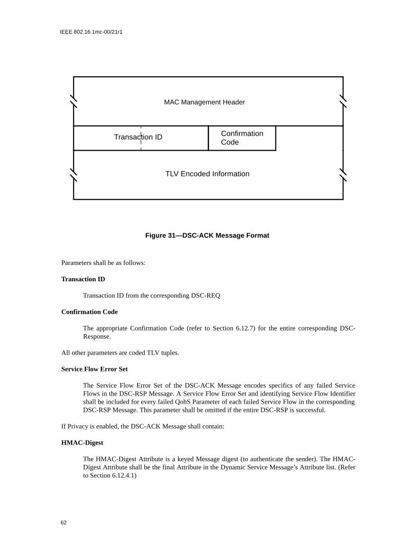
IEEE 802.16.1mc-00/21r1
efer
Parameters shall be as follows:
Transaction ID
Transaction ID from the corresponding DSC-REQ
Confirmation Code
The appropriate Confirmation Code (refer to Section 6.12.7) for the entire corresponding DSC-Response.
All other parameters are coded TLV tuples.
Service Flow Error Set
The Service Flow Error Set of the DSC-ACK Message encodes specifics of any failed ServiceFlows in the DSC-RSP Message. A Service Flow Error Set and identifying Service Flow Identifiershall be included for every failed QohS Parameter of each failed Service Flow in the correspondingDSC-RSP Message. This parameter shall be omitted if the entire DSC-RSP is successful.
If Privacy is enabled, the DSC-ACK Message shall contain:
HMAC-Digest
The HMAC-Digest Attribute is a keyed Message digest (to authenticate the sender). The HMAC-Digest Attribute shall be the final Attribute in the Dynamic Service Message’s Attribute list. (Rto Section 6.12.4.1)
Figure 31—DSC-ACK Message Format
Transaction ID
TLV Encoded Information
ConfirmationCode
MAC Management Header
62

IEEE 802.16.1mc-00/21r1
efer
6.2.18 Dynamic Service Deletion — Request (DSD-REQ) Message
A DSD-Request may be sent by a CPE or BS to delete an existing Service Flow. The format of a DSD-Request shall be as shown in Figure 32.
Parameters shall be as follows:
Service Flow Identifier
The SFID to be deleted.
Transaction ID
Unique identifier for this transaction assigned by the sender.
All other parameters are coded as TLV tuples as defined in Section 6.12.
If Privacy is enabled, the DSD-REQ shall include:
HMAC-Digest
The HMAC-Digest Attribute is a keyed Message digest (to authenticate the sender). The HMAC-Digest Attribute shall be the final Attribute in the Dynamic Service Message’s Attribute list. (Rto Section 6.12.4.1)
Figure 32—DSD-REQ Message Format
Transaction ID
TLV Encoded Information
Service Flow ID
MAC Management Header
63

IEEE 802.16.1mc-00/21r1
6.2.19 Dynamic Service Deletion — Request (DSD-RSP) Message
A DSD-RSP shall be generated in response to a received DSD-REQ. The format of a DSD-RSP shall be asshown in Figure 33.
Parameters shall be as follows:
Service Flow Identifier
SFID from the DSD-REQ to which this acknowledgement refers.
Transaction ID
Transaction ID from the corresponding DSD-REQ.
Confirmation Code
The appropriate Confirmation Code (refer to Section 6.12.7) for the corresponding DSD-REQ.
6.2.20 Multicast Polling Assignment Request (MCA-REQ) Message
The Multicast Polling Assignment message is sent to a CPE to include it in a multicast polling group. Thismessage is normally sent on a CPE’s basic connection ID. It may also be sent to a group of CPE’s on a pre-viously set up multicast connection ID. This shall be followed by a Packet PDU in the format shown in Fig-ure 34.
Figure 33—DSD-RSP Message Format
Transaction ID
TLV Encoded Information
ConfirmationCode
Service Flow ID
MAC Management Header
64
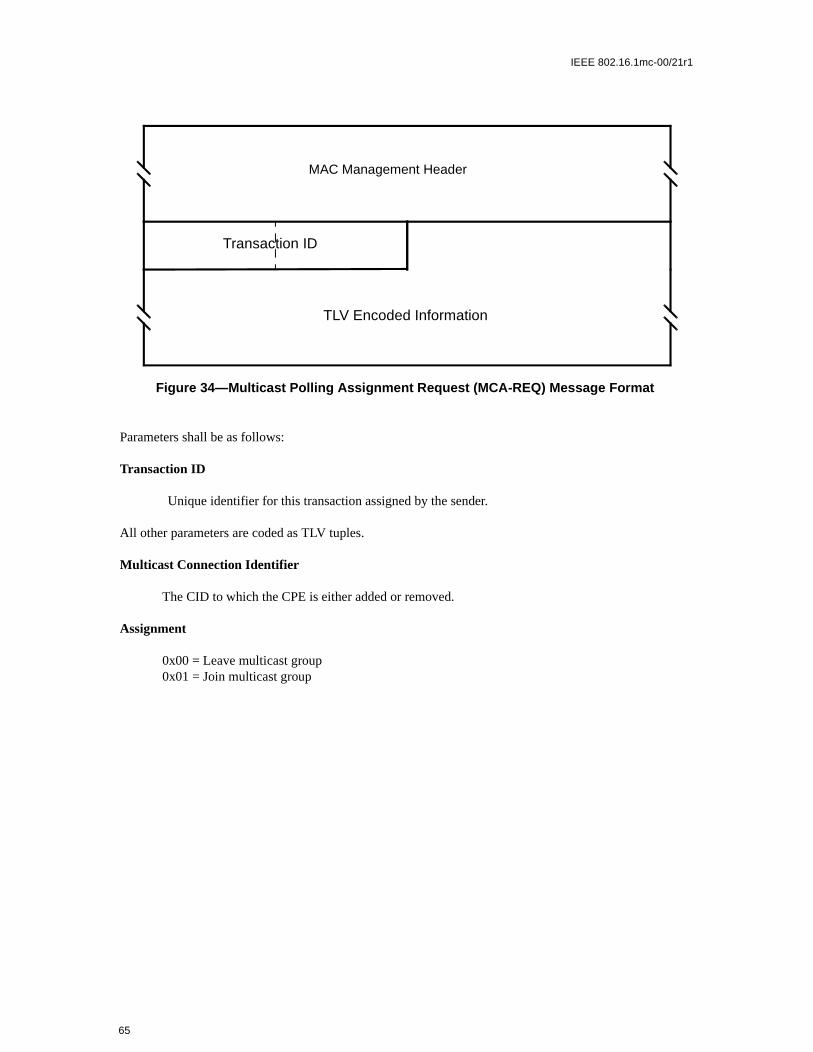
IEEE 802.16.1mc-00/21r1
Parameters shall be as follows:
Transaction ID
Unique identifier for this transaction assigned by the sender.
All other parameters are coded as TLV tuples.
Multicast Connection Identifier
The CID to which the CPE is either added or removed.
Assignment
0x00 = Leave multicast group0x01 = Join multicast group
Figure 34—Multicast Polling Assignment Request (MCA-REQ) Message Format
MAC Management Header
Transaction ID
TLV Encoded Information
65

IEEE 802.16.1mc-00/21r1
6.2.20.1 MCA-REQ TLV Encodings
The type values used shall be those defined in Table 9. The type and length fields shall each be 1 octet inlength.
6.2.21 Multicast Polling Assignment Response (MCA-RSP) Message
The Multicast Polling Assigment Response is sent by the CPE in response to a MCA-REQ. The messageformat shall be as shown in Figure 35.
Parameters shall be as follows:
Transaction ID
Unique identifier for this transaction assigned by the sender.
All other parameters are coded as TLV tuples.
Confirmation Code
0 (okay)1 (request failed)
Table 9—Multicast Assigment Request Message Encodings
Name Type(1 byte)
Length(1 byte)
Value(Variable Length)
Multicast CID 1 2
Assignment 2 1 0x00 = Leave multicast group0x01 = Join multicast group
Reserved 2-255 n Reserved for future use
Figure 35—Multicast Polling Assignment Response (MCA-RSP) Message Format
MAC Management Header
Transaction ID
TLV Encoded Information
66

IEEE 802.16.1mc-00/21r1
6.2.22 Downlink Modulation Change Request (DMC-REQ) Message
The Downlink Modulation Change Request message is sent by the CPE to the BS on the CPE’s basic con-nection ID. Normally, it is sent at the current operational modulation for the CPE. If the CPE has been inac-tive on its uplink for some period of time and detects fading on the downlink, the CPE uses this message torequest to go to a more robust (lower bits per symbol) modulation. In this case, the message is sent usingQPSK modulation to increase the likelihood of reception by the CPE. Since the CPE may not have beenallocated any uplink bandwidth, the CPE uses contention slots. The message formant shall be as shown inFigure 36.
Parameters shall be as follows:
Modulation
0x00 = QPSK0x01 = 16-QAM0x02 = 64-QAM
Figure 36—Downlink Modulation Change Request (DMC-REQ) Message Format
MAC Management Header
Modulation
67

IEEE 802.16.1mc-00/21r1
68

IEEE 802.16.1mc-00/21r1
6.3 Framing and Scheduling Intervals
The MAC is able to support both a framed and non-framed physical layer. For a framed PHY layer, theMAC aligns its scheduling intervals with the underlying PHY layer framing. For an unframed PHY layer,the scheduling intervals are chosen by the MAC to optimize system performance.
A frame is a fixed duration of time, which contains both transmit and receive intervals. The relationshipbetween upstream and downstream transmission intervals is fixed within the frame, and are both defined rel-ative to the BS internal timing. The TDD, Burst FDD and FSDD modes of operation use a framed PHYlayer. The Continuous FDD mode of operation has no explicit PHY layer framing. Instead, the upstream anddownstream transmission timings are linked via the Upstream TimeStamp within the DS-MAP and the US-MAP messages.
6.3.1 PHY Burst Mode Support
In the burst mode, the uplink and downlink can be multiplexed in a TDD fashion as described in Section6.3.1.1 or in an FDD fashion as described in Section 6.3.1.2. Each uses a frame with a duration of 1 millisec-ond. Within this frame are a downlink subframe and an uplink subframe. In the TDD case, the downlink sub-frame comes first, followed by the uplink subframe. In the burst FDD case, the downlink and uplinksubframes occur simultaneously on their respective frequencies, and occupy the whole 1 millisecond frame.In both cases, the downlink subframe is prefixed with information necessary for frame synchronization.
To aid periodic functions, multiple frames are grouped into multiframes and multiple multiframes aregrouped into hyperframes. There are 16 frames per multiframe and 32 multiframes per hyperframe. Framenumbers have the values of 0 to 15, multiframe numbers are 0 to 31, while Hyperframe numbers are from 0to 32767. Each will roll over to zero after they reach their maximum value. Since frames are 1 millisecondin duration, 1 multiframe is 16 milliseconds in duration and 1 hyperframe is 512 milliseconds in duration.
The available bandwidth in both directions is defines with a granularity of one PHY slot (PS), which has alength of 4 modulation symbols each. The number of PHY slots with each 1 mSec frame is a function of themodulation rate. The modulation rate is selected in order to obtain an integral number of PS within eachframe. For example, a 20 Mbaud modulation rate, there are 5000 PS within each 1 mS frame.
6.3.1.1 TDD Operation
In this mode of operation the downlink and uplink are on the same carrier frequency. The uplink and down-link share the same frequency in a TDM fashion. As shown in Figure 37, a TDD frame has a 1 millisecondduration and contains N PHY slots, with varying with the modulation rate. The TDD framing is adaptive inthat the number of PS allocated to downlink versus uplink can vary. The split between uplink and downlinkis a system parameter and is controlled at higher layers within the system.
69

IEEE 802.16.1mc-00/21r1
The base station MAC must be provided with time, in some form, which is synchronized to some universalsynchronization signal with at least 1 millisecond accuracy.
6.3.1.2 Burst FDD and FSDD Operation
In this mode of operation the downstream and upstream are using 2 different carrier frequencies. The fre-quency separation between carriers is set either according to the target spectrum regulations or to some valuesufficient for complying with radio channel transmit/receive isolation and desensitization requirements. Inthe time domain both upstream and downstream are frame synchronized at the BS. Figure 38 describes thebasics of the FDD and FSDD based operation.
A subscriber capable of full duplex FDD operation, meaning it is capable of transmitting and receiving at thesame instant, imposes no restriction on the base station controller regarding its upstream bandwidth alloca-tion management. On the other hand, a subscriber that is limited to half duplex FDD operation imposes arestriction on such a controller to not allocate upstream bandwidth for the subscriber during a timed whenthe subscriber must also be receiving. It is mandatory that both types of subscribers could co-exist in a FDDdeployment, meaning that radio channels could address both type of subscribers within the each frame.
At the beginning of each frame, only those users that are capable of full FDD operation can transmit duringthe time when the BS is broadcasting the Downstream MAP and Upstream MAP messages. The subscribersthat are restricted to FSDD operation must wait until the broadcast messages are finished before transmittinganything on the upstream.
Figure 37—TDD and Multiframe Structure
Adaptive
Downlink Subframe Uplink Subframe
N PHY slots = 1 mSec
Frame16(32j-31)-1
Frame16(32j-31)
Frame16(32j)-1
Frame16(32j)
Frame16(32j)-15
Multiframe 32j-31 Multiframe 32j
Hyperframe j
PS 0 PS #N-1
70

IEEE 802.16.1mc-00/21r1
6.3.2 PHY Continuous Mode Support
6.3.2.1 Continuous FDD Operation
In continuous FDD operation, the upstream and downstream signals have no defined framing, and they oper-ate on separate frequencies, which allows all subscribers to transmit on the upstream independently of whatis being transmitted on the downstream signal.
The BS periodically transmits downstream and upstream MAP messages, which are used to syncronize theupstream burst transmissions with the downstream. The usage of the mini-slots is defined by the US-MAPmessage, and can change according to the needs of the system.
6.3.3 Downlink Burst Subframe Structure
The downlink subframe defined here only applies to the burst modes (TDD, Burst FDD and FSDD).
The structure of the downlink subframe used by the BS to transmit to the CPEs has two optional forms asshown in Figure 39 and Figure 40. In both cases it starts with a Frame Control Header, which is alwaystransmitted in QAM-4. This frame header contains a preamble used by the PHY for synchronization andequalization. It also contains control sections for both the PHY and the MAC. Preambles are not RS coded,but all other downlink traffic is FEC coded. The length of the preamble in the Frame Control Header is 24QAM symbols.
In TDD systems, transmissions on the downlink for each frame are multiplexed sequentially into one contin-uous burst. The transmission is sorted by modulation with a map of the modulation changes in the PHYControl portion of the Frame Control Header. They may optionally be sorted by CPE. There is a Tx/RxTransmission Gap (TRTG) separating the downlink subframe from the uplink subframe. This structure isshown in Figure 39. Note that any one or more of the 3 differently modulated data blocks may be absent.
Burst FDD systems may use the same structure with the restriction that each half duplex user must receive inthe frame any downlink data directed to it before the user can transmit any uplink packets. If most users arefull duplex, this restriction is minor.
Alternatively, if a burst FDD system contains many half duplex users, the preferred form is to generate thedownlink subframe in a TDMA fashion. The downlink data destined to each individual CPE is grouped into
Figure 38—Burst Downstream FDD/FSDD Mapping
FRAME 0 FRAME 1 FRAME 2 FRAME 3
HALF DUPLEX USERS
HALF DUPLEX USERS
DOWNLINK
UPLINK
FULL DUPLEX USERS
BROADCAST
71

IEEE 802.16.1mc-00/21r1
P
one (preferable) or more bursts, each starting with a short (e.g., 12 symbols) preamble. In this case, the PHYControl portion of the Frame Control Header contains a map of the bursts. This option allows FSDD usersto receive or transmit in any portion of the frame as long as the bandwidth allocation preserves their halfduplex nature. This allows for greater statistical multiplexing of FSDD users at the expense of bandwidthfor the preambles and a more complex downlink map. This structure is shown in Figure 40. Note that order-ing by modulation type is not required for TDMA downlinks and not required for any uplinks.
The Frame Control Header also may periodically contain a PHY Parameters as defined in the PCD.
Figure 39—TDD and Burst FDD/TDM Downstream Subframe Structure
FrameControlHeader(QAM-4)
Data(QAM-4)
Data(QAM-16)
Data(QAM-64)
ModulationTransitions
Tx/RxTransitionGap (TDD)
Preamble PHYControl
MACControl
DL Map
Figure 40—Burst FDD/TDMA Downstream Subframe Structure
FrameControlHeader
CPE BurstStartpoints
reamble PHYControl
MACControl
DL Map
Pre
ambl
e
CPE 1Data
Pre
ambl
e
CPE 2 Data
Pre
ambl
e
CPE 3Data
Pre
ambl
e
CPE ndata
Pre
ambl
e
72

IEEE 802.16.1mc-00/21r1
6.3.3.1 PHY Control
The PHY Control portion of the downlink subframe is used for physical information destined for all CPEs.The PHY Control information is FEC encoded, but is not encrypted. The information transmitted in thissection is always transmitted in QAM-4 and includes:
a) Broadcast physical layer information (PCD)b) DL-MAPc) Frame/multiframe/hyperframe numbering or BS Upstream TimeStamp
6.3.3.2 MAC Control
The MAC Control portion of the downlink subframe is used for MAC messages destined for multiple CPEs.For information directed at an individual CPE, MAC messages are transmitted in the established controlconnection at the operating modulation of the CPE to minimize bandwidth usage. The MAC Control mes-sages are FEC encoded, but are not encrypted. The information transmitted in this section is always trans-mitted in QAM-4 and includes:
a) MAC Version Identifierb) Uplink Map (CPE/mini-slot/start symbol triplets)c) Whether any bandwidth request contention periods (see Section TBD) are included in the frame (in
US-MAP)d) Starting point and length of bandwidth request contention period, if any (in US-MAP)e) Whether registration is allowed on this physical channelf) Whether a registration contention period is included the frame (in US-MAP)g) Starting point and length of registration contention period, if any (in US-MAP)
6.3.3.3 Downlink Data
The downlink data sections are used for transmitting data and control messages to the specific CPEs. Thisdata is always FEC coded and is transmitted at the current operating modulation of the individual CPE.Message headers are sent unencrypted. Payloads of user data connections are encrypted. Payloads of MACcontrol connections are not encrypted. In the burst mode cases, data is transmitted in modulation orderQAM-4, followed by QAM-16, followed by QAM-64. The PHY Control portion of the Frame ControlHeader contains a map stating the PS and symbol at which modulation will change. In the TDMA case, thedata is grouped into CPE specific bursts, which do not need to be in modulation order.
If the downlink data does not fill the entire downlink subframe and the PHY mode is burst downstream, thetransmitter is shut-down.
6.3.4 Uplink Burst Subframe Structure
The structure of the uplink subframe used by the CPEs to transmit to the BS is shown in Figure 41. Thereare three main classes of MAC/TC messages transmitted by the CPEs during the uplink frame:
a) Those that are transmitted in contention slots reserved for station registration.b) Those that are transmitted in contention slots reserved for response to multicast and broadcast polls
for bandwidth needs. c) Those that are transmitted in bandwidth specifically allocated to individual
73

IEEE 802.16.1mc-00/21r1
6.3.4.1 Upstream Burst Mode Modulation
Adaptive modulation is used in the upstream, in which different users are assigned different modulationtypes by the base station.
In the adaptive case, the bandwidth allocated for registration and request contention slots is grouped togetherand is always used with QAM-4 modulation. The remaining transmission slots are grouped by CPE. Dur-ing its scheduled bandwidth, a CPE transmits with the modulation specified by the base station, as deter-mined by the effects of distance and environmental factors on transmission to and from that CPE. CPETransition Gaps (CTG) separate the transmissions of the various CPEs during the uplink subframe. TheCTGs contain a gap to allow for ramping down of the previous burst, followed by a preamble allowing theBS to synchronize to the new CPE. The preamble and gap lengths are broadcast periodically in the PCDmessage by the base station in the Frame Control Header.
6.3.5 Continuous Downstream and Upstream Structure
In the continuous PHY mode, the BS periodically broadcasts the Upstream MAP message (US-MAP) on thedownstream, which defines the permitted usage of each upstream mini-slot within the time interval coveredby that MAP message (see Figure 42). The timing of the upstream bursts are based upon a downstream syn-cronization message (DS-SYNC). The US-MAP messages are transmitted approximately 250 times a sec-ond, but this can vary to optimise the system’s operation.
Figure 41—Uplink Subframe Structure
RegistrationContention
Slots(QAM-4)
BW Req.Contention
Slots(QAM-4)
CPE 1Scheduled
Data(QAM-CPE 1)
CPE NScheduled
Data(QAM-CPE N)
CPETransition
Gap
Tx/RxTransitionGap (TDD)
Access Burst Access BurstCollision BandwidthRequest
CollisionBandwidthRequest
74

IEEE 802.16.1mc-00/21r1
ing IE.
t incre-
lue of the) mes- stamp
BS coun-s set by
Timeal Time
6.3.6 Upstream Map
Whether in the Burst or Continuous PHY modes, the upstream MAP message (US-MAP) defines the usagefor the upstream mini-slots using a series of Information Elements (IE), which define the useage of eachupstream interval. The US-MAP defines the upstream usage in terms of the offset from the prevoius IE start(the lenfth) in numbers of mini-slots.
Each IE consists of a 16-bit Connection ID, a 4-bit type code, and a 12-bit starting mini-slot offset as definedin Section 6.2.4. Since all CPE must scan all IE within each MAP, it is critical that IEs be short and relativelyfixed format. IEs within the MAP are strictly ordered by starting offset. For most purposes, the durationdescribed by the IE is inferred by the difference between the IE’s starting offset and that of the followFor this reason, a Null IE shall terminate the list.
6.3.6.1 Upstream Timing
The upstream timing is based on the Upstream Time Stamp reference, which is a 29-bit counter thaments at a rate that is 4 times the modulation rate. It therefore has a resolution that equals ¼th of the modula-tion symbol period. This allows the CPE to track the BS clock with a small time offset.
The BS maintains a separate Upstream Time Stamp for each upstream at the base station. The vaBS Upstream Time Stamp is broadcast to all the CPE using the Physical Channel Descriptor (PCDsage. Each CPE maintains its own Upstream Time Stamp so that it is syncronous with the BS Timefor the upstream channel that it is using. The CPE Time Stamp must change at the same rate as its terpart, but will be offset so that the upstream bursts arrive at the BS at the correct time. This offset ithe BS using the RNG-RSP message.
6.3.6.1.1 Continuous Mode Upstream Timing
The downstream MAP message (DS-MAP) in the continuous PHY mode broadcasts the UpstreamStamp value to all CPE. The Upstream Time Stamp from the BS is then used to adjust the CPE intern
Figure 42—Continuous Downstream FDD Mapping
CM tx opportunity CM tx opportunityrequest contention area
current mapprevious map
as-yetunmapped
time
mini-slots
maintenance
permitted use of the upstream channel
transmitted on downstream channel by the CMTSMap PDU transmitted on downstream channel by BSUS-MAP
75

IEEE 802.16.1mc-00/21r1
ini-or eachS 4N.
with (up tombols/
that
. In thestrates
ignifi-tamp
Stamp so that it tracks the BS timing. The CPE Time Stamp is offset from the BS Time Stamp by the TimingAdjustment amount sent to each CPE in the RNG-RSP message. The offset causes the upstream bursts arriveat the BS at the proper time. After either the BS or CPE Time Stamps reach the maximum value of 229-1,they roll over to zero and continue to count.
6.3.6.1.2 Burst Mode Upstream Timing
In the burst PHY modes, at the start of each 1 mSec frame the Upstream Time Stamp counter in the BS isreset to zero, while in the CPE it is reset using the current Timing Adjustment value as sent from the BSusing the RNG-RSP message. Thus, the CPE Time Stamp will be offset from the BS Time Stamp so that theupstream bursts arrive at the BS at the proper time.
6.3.6.2 Upstream Mini-Slot Definition
The upstream bandwidth allocation MAP (US-MAP) uses time units of “mini-slots.” The size of the mslot (N) is specified as a number of PHY slots (PS) and is carried in the Physical Channel Descriptor fupstream channel. One mini-slot contains N PHY slots (PS), where N = 2m (where m = 0..7). Since each Pcontains 4 modulation symbols, the number of modulation symbols contained in one mini-slot equals
Practical mini-slots are expected to represent relatively few PS to allow efficient bandwidth utilizationrespect to the mini-slot size. Larger mini-slot sizes allow the BS to define large contention intervals212-1 or 4095 mini-slots) using the current US-MAP. Note that the modulation level and hence the sybyte is a characteristic of an individual burst transmission, not of the channel.
A “mini-slot” is the unit of granularity for upstream transmission allocations. There is no implicationany PDU can actually be transmitted in a single mini-slot.
In a framed mode of operation, the mini-slot represents the granularity of upstream allocation unitsnon-frame mode, the mini-slot definition is related to a timestamp generated by the BS. Figure 42 illuthe mapping of the Upstream Time Stamp maintained in the BS to the BS Mini-slot Counter.
The BS and CPE base the upstream allocations on a 29-bit counter that normally counts to (229 - 1) and thenwraps back to zero. The bits (i.e., bit 0 to bit 28-3-M) of the mini-slot counter shall match the most-scant bits (i.e., bit 3+M to bit 28) of the DS-MAP timestamp counter. That is, mini-slot N begins at times
03
Additional BSResolution
28 3+M
Mini-SlotSize (2M)
028-3-M
BS Upstream Time Stamp(PS Tick = SymbolTime x 4)
Mini-slot Counter
SymbolTime/4SymbolTime x 4
Figure 43—BS System and Mini-slot Clocks
76

IEEE 802.16.1mc-00/21r1
value (N*T*16), where T = 2M is the PCD multiplier that defines the mini-slot size (i.e., the number of PSper mini-slot).
The constraint that the PCD multiplier be a power of two has the consequence that the number of PS permini-slot must also be a power of two.
6.3.6.3 Upstream Interval Definition
All of the Information Elements defined below shall be supported by conformant CPEs. Conformant BSmay use any of these Information Elements when creating a US-MAP message.
6.3.6.3.1 The Request IE
The Request IE provides an upstream interval in which requests may be made for bandwidth for upstreamdata transmission. The character of this IE changes depending on the type of Connection ID used in the IE. Ifbroadcast, this is an invitation for CPEs to contend for requests. If unicast, this is an invitation for a particu-lar CPE to request bandwidth. Unicasts may be used as part of a Quality of Service scheduling scheme that isvendor dependent. PDUs transmitted in this interval shall use the Bandwidth Request Header Format (referto Section 6.2).
A small number of Priority Request CIDs are defined in Section 6.1. These allow contention for Request IEsto be limited to service flows of a given Traffic Priority (Section 6.12.5.5.2).
6.3.6.3.2 The Initial Maintenance IE
The Initial Maintenance IE provides an interval in which new stations may join the network. A long interval,equivalent to the maximum round-trip propagation delay plus the transmission time of the Ranging Request(RNG-REQ) message, shall be provided in some US-MAPs to allow new stations to perform initial ranging.Packets transmitted in this interval shall use the RNG-REQ MAC Management message format (refer toSection 6.2.5).
6.3.6.3.3 The Station Maintenance IE
The Station Maintenance IE provides an interval in which stations are expected to perform some aspect ofroutine network maintenance, such as ranging or power adjustment. The BS may request that a particularCPE perform some task related to network maintenance, such as periodic transmit power adjustment. In thiscase, the Station Maintenance IE is unicast to provide upstream bandwidth in which to perform this task.Packets transmitted in this interval shall use the RNG-REQ MAC Management message format (see Section6.2.5).
6.3.6.3.4 Short and Long Data Grant IEs
The Short and Long Data Grant IEs provide an opportunity for a CPE to transmit one or more upstreamPDUs. These IEs are issued either in response to a request from a station, or because of an administrativepolicy providing some amount of bandwidth to a particular station (see class-of-service discussion in Sec-tion TBD). These IEs may also be used with an inferred length of zero mini slots (a zero length grant), toindicate that a request has been received and is pending (a Data Grant Pending).
Short Data Grants are used with intervals less than or equal to the maximum burst size for this usage speci-fied in the Upstream Channel Descriptor. If Short Data burst profiles are defined in the UCD, then all LongData Grants shall be for a larger number of mini-slots than the maximum for Short Data. The distinctionbetween Long and Short Data Grants may be exploited in physical-layer forward-error-correction coding;otherwise, it is not meaningful to the bandwidth allocation process.
77

IEEE 802.16.1mc-00/21r1
If this IE is a Data Grant Pending (a zero length grant), it shall follow the NULL IE. This allows CPEmodems to process all actual allocations first, before scanning the Map for data grants pending and dataacknowledgments.
6.3.6.3.5 Expansion IE
The Expansion IE provides for extensibility, if more than 16 code points or 32 bits are needed for future IEs.
6.3.6.3.6 Null IE
A Null IE terminates all actual allocations in the IE list. It is used to infer a length for the last interval. AllData Acknowledge IEs and All Data Grant Pending IEs (Data Grants with an inferred length of 0) must fol-low the Null IE.
6.3.7 Requests
Requests refer to the mechanism that CPE use to indicate to the BS that it needs upstream bandwidth alloca-tion. A Request may come as a stand-alone Bandwidth Request Header (refer to Section TBD) or it maycome as a piggyback request (refer to Section 6.7.3).
Because the modulation format of the upstream can dynamically change, all requests for bandwidth shall bemade in terms of the number of bytes needed to carry the MAC header and payload, but not the PHY layeroverhead.
The Bandwidth Request Message may be transmitted during any of the following intervals:
a) Request IEb) Short Data Grant IEc) Long Data Grant IE
The number of bytes requested shall be the total number that are desired by the CPE at the time of therequest (excluding any physical layer overhead), subject to PCD1 and administrative limits2.
The CPE shall have only one request outstanding at a time per Connection ID. If the BS does not immedi-ately respond with a Data Grant, the CPE is able to unambiguously determine that its request is still pendingbecause the BS shall continue to issue a Data Grant Pending in every MAP for as long as a request is unsat-isfied.
6.3.8 MAP Relevance and Synchronization
6.3.8.1 MAP Relevance for Burst PHY Systems
The information in the PHY Control portion of the Frame Control Header pertains to the current frame (i.e.,the frame in which it was received). The information in the Uplink Subframe Map in the MAC Control por-tion of the Frame Control Header pertains to the following frame (i.e., one frame after it is received). This
1The CPE is limited by the Maximum Burst size for the Long Data Grant IUC in the PCD.2The CPE is limited by the Maximum Concatenated Burst for the Service Flow
78

IEEE 802.16.1mc-00/21r1
timing holds for both the TDD and FDD variants of the burst system. The TDD variant is shown in Figure44. The FDD variant is shown in Figure 45.
6.3.8.2 MAP Relevance for Continuous PHY Systems
In the Continuous PHY system, the downstream MAP (DS-MAP) only contains the Upstream Time Stamp,and does not define what information is being transmitted. All CPE continuously search the downstream sig-nal for any downstream message that is addressed to them. The Upstream MAP (US-MAP) message in thedownstream contains the Time Stamp that indicates the first mini-slot that the MAP defines.
The delay from the end of the US-MAP to the beginning of the first Upstream interval defined by the MAPshall be greater than maximum round trip delay plus the processing time required by the CPE.(see Figure46)
Figure 44—Time Relevance of PHY and MAC Control Information (TDD)
ATDD SplitMAC Ctrl n
PHY Ctrl n-1
MAC Ctrl n+1
PHY Ctrl n
MAC Ctrl n+2
PHY Ctrl n+1
MAC Ctrl n+3
PHY Ctrl n+2
ATDD Split ATDD Split ATDD Split
QAM16 QAM64
Frame n-1 Frame n Frame n+1 Frame n+2
QAM16 QAM64 QAM16 QAM64
UplinkSubframe
DownlinkSubframe
FrameControl
Figure 45—Time Relevance of PHY and MAC Control Information (FDD)
MAC Ctrl n
PHY Ctrl n-1
MAC Ctrl n+1
PHY Ctrl n
MAC Ctrl n+2
PHY Ctrl n+1
MAC Ctrl n+3
PHY Ctrl n+2
QAM16 QAM64
Frame n-1 Frame n Frame n+1 Frame n+2
QAM16 QAM64 QAM16 QAM64
UplinkSubframe
DownlinkSubframe
FrameControl
79

IEEE 802.16.1mc-00/21r1
6.4 Contention Resolution
The BS controls assignments on the upstream channel through the US-MAP and determines which mini-slots are subject to collisions. The BS may allow collisions on either Requests or Data PDUs.
This section provides an overview of upstream transmission and contention resolution. For simplicity, itrefers to the decisions a CPE makes, however, this is just a instructional tool. Since a CPE can have multipleupstream Service Flows (each with its own CID) it makes these decisions on a per service queue or per CIDbasis.
The mandatory method of contention resolution which shall be supported is based on a truncated binaryexponential back-off, with the initial back-off window and the maximum back-off window controlled by theBS. The values are specified as part of the Upstream Bandwidth Allocation Map (US-MAP) MAC messageand represent a power-of-two value. For example, a value of 4 indicates a window between 0 and 15; a valueof 10 indicates a window between 0 and 1023.
When a CPE has information to send and wants to enter the contention resolution process, it sets its internalback-off window equal to the Data Backoff Start defined in the US-MAP currently in effect.3
The CPE shall randomly select a number within its back-off window. This random value indicates the num-ber of contention transmit opportunities which the CPE shall defer before transmitting. A CPE shall onlyconsider contention transmit opportunities for which this transmission would have been eligible. These aredefined by either Request IEs in the US-MAP. Note: Each IE can represent multiple transmission opportuni-ties.
As an example, consider a CPE whose initial back-off window is 0 to 15 and it randomly selects the number11. The CPE must defer a total of 11 contention transmission opportunities. If the first available Request IEis for 6 requests, the CPE does not use this and has 5 more opportunities to defer. If the next Request IE isfor 2 requests, the CPE has 3 more to defer. If the third Request IE is for 8 requests, the CPE transmits on thefourth request, after deferring for 3 more opportunities.
After a contention transmission, the CPE waits for a Data Grant (Data Grant Pending) in a subsequent MAP.Once received, the contention resolution is complete. The CPE determines that the contention transmission
3The MAP currently in effect is the MAP whose allocation start time has occurred but which includes IEs that have not occurred.
Figure 46—Time Relevance of Upstream MAP Information (Continuous FDD)
Uplink
Downlink
> round trip delay + Tproc
US-MAP US-MAP US-MAP
80

IEEE 802.16.1mc-00/21r1
Service
AP.
was lost when it finds a MAP without a Data Grant (Data Grant Pending) for it and with an Ack time morerecent than the time of transmission. The CPE shall now increase its back-off window by a factor of two, aslong as it is less than the maximum back-off window. The CPE shall randomly select a number within itsnew back-off window and repeat the deferring process described above.
This re-try process continues until the maximum number of retries (16) has been reached, at which time thePDU shall be discarded. Note: The maximum number of retries is independent of the initial and maximumback-off windows that are defined by the BS.
If the CPE receives a unicast Request or Data Grant at any time while deferring for this CID, it shall stop thecontention resolution process and use the explicit transmit opportunity.
The BS has much flexibility in controlling the contention resolution. At one extreme, the BS may choose toset up the Data Backoff Start and End to emulate an Ethernet-style back-off with its associated simplicityand distributed nature, but also its fairness and efficiency issues. This would be done by setting Data Back-off Start = 0 and End = 10 in the US-MAP. At the other end, the BS may make the Data Backoff Start andEnd identical and frequently update these values in the US-MAP so all CPE are using the same, and hope-fully optimal, back-off window.
6.4.1 Transmit Opportunities
A Transmit Opportunity is defined as any mini-slot in which a CPE may be allowed to start a transmission.Transmit Opportunities typically apply to contention opportunities and are used to calculate the properamount to defer in the contention resolution process.
The number of Transmit Opportunities associated with a particular IE in a MAP is dependent on the totalsize of the region as well as the allowable size of an individual transmission. As an example, assume a REQIE defines a region of 12 mini-slots. If the UCD defines a REQ Burst Size that fits into a single mini-slotthen there are 12 Transmit Opportunities associated with this REQ IE, i.e., one for each mini-slot. If the PCDdefines a REQ that fits in two mini-slots, then there are six Transmit Opportunities and a REQ can start onevery other mini-slot.
Transmit opportunities shall not overlap and the start time of the transmit opportunity shall align with eitherthe start of the IE interval or at the end of the previous transmit opportunity.
6.5 Fragmentation
Fragmentation is the processby which a portion of a convergence sub-layer payload is divided into two ormore MAC PDUs. This process is undertaken to allow efficient use of available bandwidth relative to theQoS requirements of a connections Service Flow.
Fragmentation may be initiated by a BS for a downlink connection. Fragmentation may be initiated by aCPE for an uplink connection. A connection may be in only one fragmentation state at any given time. Aconnection that is not in the fragmentation state shall set the FC and FSN fields of a Connection’s Flow to 0 and 0000, respectively.
The authority to fragment a traffic on a connection is defined when the connecion is created by a MS
81

IEEE 802.16.1mc-00/21r1
The fragments are set in accordance with Table 10.
The sequence number allows the receiving terminal to re-create the original payload and to detect the loss ofany intermediate packets. Upon loss, the receiving station shall discard all PDUs on the connection until anew fragment is detected or a non-fragmented PDU is detected.
6.6 Upstream Service
The following sections define the basic upstream Service Flow scheduling services and list the QoS parame-ters associated with each service. A detailed description of each QoS parameter is provided in Section6.12.5.
Scheduling services are designed to improve the efficiency of the poll/grant process. By specifying a sched-uling service and its associated QoS parameters, the BS can anticipate the throughput and latency needs ofthe upstream traffic and provide polls and/or grants at the appropriate times.
Each service is tailored to a specific type of data flow as described below. The basic services comprise:Unsolicited Grant Service (UGS), Real-Time Polling Service (rtPS), Unsolicited Grant Service with ActivityDetection (UGS-AD), Non-Real-Time Polling Service (nrtPS) and Best Effort (BE) service.
Table 10—Fragmentation Rules
Fragment FC FSN
First Fragment 10 0000
Continuing Fragment 11 incremented modulo 16
Last Fragment 01 incremented modulo 16
Table 11—Scheduling Services and Usage Rules
SchedulingType
Piggy-BackRequest
BandwidthStealing Pollng
UGS Not Alloweda
aAlso a function of the MAC Header
Not allowed PM bit is used to request a unicast poll for bandwidth needs of non-UGS connections
UGS-AD Not Allowed Not allowed Not allowed
rtPS Allowed Allowed for GPT Scheduling only allows unicast polling
nrtPS Allowed Allowed for GPT Scheduling may restrict a service flow to unicast poll-ing via the transmission/request policy; otherwise all forms of polling are allowed
BE Allowed Allowed for GPT All forms of polling allowed
82

IEEE 802.16.1mc-00/21r1
eriodicPolicytentiononnec-ing thetream to thehe keyd Grant
statust bit ofts that
w's trans-term
eter ofd is set.n. The
ariable unicast of thesizes for
ly, thehibited
requestg onlystill use Policy
g to net-ll Jit-
thate overunicastiency
6.6.1 Unsolicited Grant Service
The Unsolicited Grant Service (UGS) is designed to support real-time service flows that generate fixed sizedata packets on a periodic basis, such as T1/E1 and Voice over IP. The service offers fixed size grants on areal-time periodic basis, which eliminate the overhead and latency of CPE requests and assure that grantswill be available to meet the flow’s real-time needs. The BS shall provide fixed size data grants at pintervals to the Service Flow. In order for this service to work correctly, the Request/Transmission (refer to Section 6.12.5.6.3) setting shall be such that the CPE is prohibited from using any conrequest opportunities and the BS SHOULD not provide any unicast request opportunities for that ction. Piggy-back requests may be used to request additional bandwidth for a different connection usBandwidth Request Header. This will result in the CPE only using unsolicited data grants for upstransmission on that connection. All other bits of the Request/Transmission Policy are not relevantfundamental operation of this scheduling service and should be set according to network policy. Tservice information elements are the Unsolicited Grant Size, the Nominal Grant interval, the TolerateJitter and the Request/Transmission Policy. (Refer to TBD)
The Bandwidth Management fiels in the Generic MAC Header (refer to Figure 2) is used to passinformation from the CPE to the BS regarding the state of the UGS Service Flow. The most significanthe Bandwidth Management field is the Slip Indicator (SI) bit. The CPE shall set this flag once it detecthis Service Flow has exceeded its transmit queue depth. Once the CPE detects that the Service Flomit queue is back within limits, it shall clear the SI flag. The flag allows the BS to provide for long compensation for conditions such as lost maps or clock rate mismatch’s by issuing additional grants.
The BS shall not allocate more grants per Nominal Grant Interval than the Grants Per Interval paramthe Active QoS Parameter Set, excluding the case when the SI bit of the Bandwidth Management fielIn this case, the BS may grant up to 1% additional bandwidth for clock rate mismatch compensatioactive grants field of the Bandwidth Management field is ignored with UGS service.
6.6.2 Real-Time Polling Service
The Real-Time Polling Service (rtPS) is designed to support real-time service flows that generate vsize data packets on a periodic basis, such as MPEG video. The service offers real-time, periodic,request opportunities, which meet the flow's real-time needs and allow the CPE to specify the sizedesired grant. This service requires more request overhead than UGS, but supports variable grant optimum data transport efficiency.
The BS shall provide periodic unicast request opportunities. In order for this service to work correctRequest/Transmission Policy setting (refer to Section 6.12.5.6.3) shall be such that the CPE is profrom using any contention request opportunities for that connection. The BS may issue unicast opportunities as prescribed by this service even if a grant is pending. This will result in the CPE usinunicast request opportunities in order to obtain upstream transmission opportunites (the CPE could unsolicited data grants for upstream transmission as well). All other bits of the Request/Transmissionare not relevant to the fundamental operation of this scheduling service and should be set accordinwork policy. The key service information elements are the Nominal Polling Interval, the Tolerated Poter and the Request/Transmission Policy.
6.6.3 Unsolicited Grant Service with Activity Detection
The Unsolicited Grant Service with Activity Detection (UGS/AD) is designed to support UGS flowsmay become inactive for substantial portions of time (i.e. tens of milliseconds or more), such as VoicIP with silence suppression. The service provides Unsolicited Grants when the flow is active and polls when the flow is inactive. This combines the low overhead and low latency of UGS with the efficof rtPS. Though USG/AD combines UGS and rtPS, only one scheduling service is active at a time.
83

IEEE 802.16.1mc-00/21r1
The BS shall provide periodic unicast grants, when the flow is active, but shall revert to providing periodicunicast request opportunities when the flow is inactive. [The BS can detect flow inactivity by detectingunused grants. However, the algorithm for detecting a flow changing from an active to an inactive state isdependent on the BS implementation]. In order for this service to work correctly, the Request/TransmissionPolicy setting (refer to Section 6.12.5.6.3) shall be such that the CPE is prohibited from using any contentionrequest a opportunities. This results in the CPE using only unicast request opportunities in order to obtainupstream transmission opportunities. However, the CPE will use unsolicited data grants for upstream trans-mission as well. All other bits of the Request/Transmission Policy are not relevant to the fundamental opera-tion of this scheduling service and should be set according to network policy. The key service parametersare the Nominal Polling Interval, the Tolerated Poll Jitter, the Nominal Grant Interval, the Tolerated GrantJitter, the Unsolicited Grant Size and the Request/Transmission Policy.
In UGS-AD service, when restarting UGS after an interval of rtPS, the BS SHOULD provide additionalgrants in the first (and/or second) grant interval such that the CPE receives a total of one grant for each grantinterval from the time the CPE requested restart of UGS, plus one additional grant. Because the ServiceFlow is provisioned as a UGS flow with a specific grant interval and grant size, when restarting UGS, theCPE shall not request a different sized grant than the already provisioned UGS flow. As with any ServiceFlow, changes can only be requested with a DSC command.
The Bandwidth Management Field allows for the CPE to dynamically state how many grants per interval arerequired to support the number of flows with activity present. In UGS/AD, the CPE may use the Slip Indica-tor Bit in the Bandwidth Management Field. The remaining seven bits of the Bandwith Management Fielddefine the Active Grants field. This field defines the number of grants within a Nominal Grant Interval thatthis Service Flow currently requires. When using UGS/AD, the CPE shall indicate the number of requestedgrants per Nominal Grant Interval in this field. The Active Grants field is ignored with UGS without Activ-ity Detection. This field allows the CPE to signal to the BS to dynamically adjust the number of grants perinterval that this UGS Service Flow is actually using. The CPE shall not request more than the number ofGrants per Interval in the ActiveQoSParameterSet.
6.6.4 Non-Real-Time Polling Service
The Non-Real-Time Polling Service (nrtPS) is designed to support non real-time service flows that requirevariable size data grants on a regular basis, such as high bandwidth FTP. The service offers unicast polls on aregular basis which assures that the flow receives request opportunities even during network congestion.The BS typically polls nrtPS CIDs on an (periodic or non-periodic) interval on the order of one second orless.
The BS shall provide timely unicast request opportunities. In order for this service to work correctly, theRequest/Transmission Policy setting (refer to Section 6.12.5.6.3) SHOULD be such that the CPE is allowedto use contention request opportunities. This will result in the CPE using contention request opportunities aswell as unicast request opportunities and unsolicited data grants. All other bits of the Request/TransmissionPolicy are not relevant to the fundamental operation of this scheduling service and should be set according tonetowrk policy. The key service elements are Nominal Polling Interval, Minimum Reserved Traffic Rate,Maximum Sustained Traffic Rate, Request/Transmission Policy and Traffic Priority.
6.6.5 Best Effort Service
The intent of the Best Effort (BE) service is to provide efficient service to best effort traffic. In order for thisservice to work correctly, the Request/Transmission Policy setting SHOULD be such that the CPE isallowed to use contention request opportunities. This will result in the CPE using contention request oppor-tunities as well as unicast request opportunities and unsoliced data grants. All other bits of the Request/Transmission Policy are not relevant to the fundamental operation of this scheduling service and should beset according to network policy. The key service elements are the Minimum Reserved Traffic Rate, theMaximum Sustained Traffic Rate, and the Traffic Priority.
84

IEEE 802.16.1mc-00/21r1
6.7 Bandwidth Allocation and Request Mechanisms
Note that at registration every CPE is assigned two dedicated connection IDs for the purpose of sending andreceiving control messages. Two connections are used to allow differentiated levels of QoS to be applied tothe different connections carrying MAC management traffic. Increasing (or decreasing) bandwidth require-ments is necessary for all services except uncompressible constant bit rate CG services. The needs ofuncompressible CG services do not change between connection establishment and termination. The require-ments of compressible CG services, such as channelized T1, may increase or decrease depending on traffic.DAMA services are given resources on a demand assignment basis, as the need arises.
When a CPE needs to ask for bandwidth on a connection with Best Effort scheduling service, it sends a mes-sage to the BS containing the immediate requirements of the DAMA connection. QoS for the connectionwas established at connection establishment and is looked-up by the BS.
There are numerous methods by which the CPE can get the bandwidth request message to the BS.
6.7.1 Polling
Polling is the process by which the BS allocates to the CPEs bandwidth specifically for the purpose of mak-ing bandwidth requests. These allocations may be to individual CPEs or to groups of CPEs. Allocations togroups of connections and/or CPEs actually define bandwidth request contention IEs. The allocations arenot in the form of an explicit message, but are contained as a series of Information Elements (IE) within theUplink Map.
Note that polling is done on either a CPE or connection basis. Bandwidth is always requested on a connec-tion ID basis and bandwidth is allocated on either a connection or CPE basis (based on CPE capability).
6.7.1.1 Unicast
When a CPE is polled individually, no explicit message is transmitted to poll the CPE. Rather, the CPE isallocated, in the UL-Map, bandwidth sufficient to respond with a bandwidth request. If the CPE does notneed bandwidth, it returns a request for 0 bytes (Note that 0 byte requests are only used in the individualpolling case since explicit bandwidth for a reply has been allocated.). CPEs operating in GPT mode, whichhave an active UGS connection, may not be polled individually unless they set the Poll Me (PM) bit in theheader of a packet on the UGS connection. Only inactive CPEs and CPEs explicitly requesting to be polledwill be polled individually. This saves bandwidth over polling all CPEs individually. Active CPEs respondto polling at their current uplink modulation, while inactive CPEs must respond at QAM-4 to ensure theirtransmission is robust enough to be detected by the BS.
The interpretation of bandwidth requests by the base station differs for UGS connections and Best Effortconnections. For UGS connections, the effect of a bandwidth request is to change the bandwidth allocatedevery frame. For Best Effort connections, the effect is to reset the base station’s perception of the data pend-ing at the CPE for that connection.
The information exchange sequence for individual polling is shown in Figure 47.
85

IEEE 802.16.1mc-00/21r1
Figure 47—Unicast Polling
Individual Pollingof CPEs
More BWavailable for
individualpolling?
Unpolled CPEswith poll me bit
set?
Unpolled,inactive CPEs?
Set up poll toindividual CPE &mark as polled.
At CPE’s operationalmodulation
Initiate multicastand broadcast
polling algorithm.
Were anyindividual polls
set up?
Await individualBW requests inscheduled CPE
uplink time.
BW Requests?
Use BW allocationalgorithm &
change uplinksubframe map.
Done
Yes
No
No
Yes
Yes
No
Yes
Yes
No
No
CPE-2Data
Reg ContSlots
CPE NData
CPE-1Data
BW Request
BW ReqSlots
PHY/MACCONTROL
QAM-64Data
QAM-16Data
QAM-4Data
PreambleMAC
ControlPHY
Control
Uplink Map
CPE k BWAllocation
PHY/MACCONTROL
QAM-64Data
QAM-16Data
QAM-4Data
CPE k additional BW Allocation
PreambleMAC
ControlPHY
Control
Uplink Map
CPE’swith expired
polling interval?
86

IEEE 802.16.1mc-00/21r1
6.7.1.2 Multicast and Broadcast
If there are more CPEs that are inactive than there is bandwidth available for individual polling, some CPEsmay be polled in multicast groups and a broadcast poll may be issued. Certain connection IDs are reservedfor multicast groups and for broadcast messages, as described in Table 1. As with individual polling, thepoll is not an explicit message but bandwidth allocated in the Uplink Map. The difference is that rather thanassociating allocated bandwidth with a CPE’s basic connection ID, the allocation is to a multicast or broad-cast connection ID.
When the poll is directed at a multicast or broadcast connection ID, CPEs belonging to the polled group mayrequest bandwidth using Request Intervals allocated in the uplink frame. With multicast and broadcast poll-ing, to reduce the likelihood of collision, only CPE’s needing bandwidth reply. Zero-length bandwidthrequests are not allowed in Request intervals. CPEs always transmit using the modulation defined in theburst profile in the Request intervals. This will typically be at QPSK modulation.
If the BS does not respond with an error message or a bandwidth allocation within the expiration of timerMT5, the CPE assumes a collision has occurred and uses the a truncated binary exponential back-off algo-rithm (see Section 6.4) to try at another contention opportunity. The multicast and broadcast polling processis shown in Figure 48.
Table 12—Sample Upstream Map with Multicast and Broadcast IE
Interval Description Upstream MAP Information Element Fields
CID(16 bits)
IUC(4 bits)
Offset(12 bits)
Registration 0xFFFF 1 0
Multicast group 0xFFC5 Bandwidth Request
0xFFC5 1 405
Multicast group 0xFFDA Bandwidth Request
0xFFDA 1 200
Broadcast Bandwidth Request
0xFFFF 1 200
CPE 5 Uplink Grant 0x007B 4 156
CPE 21 Uplink Grant 0x01C9 7 75
* * * *
* * * *
* * * *
87

IEEE 802.16.1mc-00/21r1
Figure 48—Multicast and Broadcast Polling
Multicast andbroadcast polling
Bandwidthavailable for
multicast polls?
Bandwidthavailable forbroadcast
polls?
Poll next multicastgroup in MACControl block
Place broadcastpoll in MAC
Control block
Multicast orbroadcast polls
set up?
Monitor BWRequest
Contention Slotsfor BW requests
Valid (non-collision) BW
requests
Use BW allocationalgorithm &
change uplinksubframe map.
Done
Yes
No
Yes
No
Yes
Yes
No
No
PHY/MACCONTROL
QAM-64Data
QAM-16Data
QAM-4Data
PreambleMAC
ControlPHY
Control
Uplink Map
CPE k BWAllocation
PHY/MACCONTROL
QAM-64Data
QAM-16Data
QAM-4Data
PreambleMAC
ControlPHY
Control
Uplink Map
CPE-2Data
Reg ContSlots
CPE NData
CPE-1Data
BW Requests
BW ReqSlots
Collision CPE IDConnection ID
Amount
Multicast orBroadcast Poll
88

IEEE 802.16.1mc-00/21r1
6.7.2 Poll-Me Bit
CPEs with currently active USG connections may set the poll me bit (bit PM in the MAC header GM field)in a MAC packet of the USG connection to indicate to the BS that they need polled to request bandwidth.To reduce the bandwidth requirements of individual polling, CPEs with active USG connections need beindividually polled only if the Poll-Me bit is set (or if the interval of the USG is too long to satisfy the QoSof the CPEs other connections). Once the BS detects this request for polling, the process for individual poll-ing is used to satisfy the request. The procedure by which a CPE stimulates the BS to poll it is shown in Fig-ure 49. To minimize the risk of the BS missing the poll me bit, the CPE may set the bit in all USG MACheaders in the frame.
6.8 Network Entry and Initialization
The procedure for initialization of a CPE modem shall be as shown in Figure 50. This figure shows the over-all flow between the stages of initialization in a CPE. This shows no error paths, and is simply to provide anoverview of the process. The more detailed finite state machine representations of the individual sections(including error paths) are shown in the subsequent figures. Timeout values are defined in Section 6.11.
The procedure can be divided into the following phases:
Figure 49—Poll Me Bit Usage
Poll Me Bit Usage
Piggybacking& BW Stealing
exhausted?
Attemptpiggybacking &
BW Stealing first
USG Packetavailable?
Set PM=1 inMAC header
Done
Yes
No
Yes
No
89

IEEE 802.16.1mc-00/21r1
a) Scan for downstream channel and establish synchronization with the BS.b) Obtain transmit parameters (from PCD message)c) Perform rangingd) Establish IP connectivity e) Establish time of dayf) Transfer operational parametersg) Perform registrationh) Privacy initialization (if provisioned to utilize Privacy capabilities)
Each CPE contains the following information when shipped from the manufacturer:
a) A unique EUI-64 MAC address which is assigned during the manufacturing process. This is used toidentify the modem to the various provisioning servers during initialization.
b) Security information as defined in Section 7 (e.g., X.509 certificate) used to authenticate the CPE tothe security server and authenticate the responses from the security and provisioning servers.
90

IEEE 802.16.1mc-00/21r1
6.8.1 Scanning and Synchronization to Downstream
On initialization or after signal loss, the CPE modem shall acquire a downstream channel. The CPE shallhave non-volatile storage in which the last operational parameters are stored and shall first try to re-acquirethis downstream channel. If this fails, it shall begin to continuously scan the possible channels of the down-stream frequency band of operation until it finds a valid downstream signal.
Figure 50— CPE Initialization Overview
Scan forDownstream
Channel
BaselinePrivacy
Initialization
Operational
*1 *1:Baseline Privacy
enabled
Baseline Privacy
Initialized
DownstreamSync
Established
ObtainUpstream
Parameters
Ranging &Automatic
Adjustments
Upstream Parameters
Aquired
Ranging &Auto AdjComplete
EstablishIP
Connectivety
IPComplete
EstablishTime of
Day
Time of Day Established
TransferOperationalParameters
Transfer Complete
Registerwith
CMTS
Registration Complete
No
Yes
BS
PrivacyEnabled
91

IEEE 802.16.1mc-00/21r1
for its PCD
ssagehannel.
and are channel
annel to find
ameters.l. If theall waithe CPEstream
en there chan-
A downstream signal is considered to be valid when the CPE has achieved the following steps:
a) synchronization of the modulation symbol timingb) synchronization of the convolutional decoder if presentc) synchronization of the FEC framingd) synchronization of the MPEG packetizatione) recognition of PCD MAC messages
This implies that it has locked onto the correct frequency, equalized the downstream channel, recovered anyPMD sublayer framing and the FEC is operational (refer to Section TBD). At this point, a valid bit stream isbeing sent to the transmission convergence sublayer. The transmission convergence sublayer performs itsown synchronization. On detecting the well-known BWA PID, along with a payload unit start indicator per[ITU-T H.222.0], it delivers the MAC frame to the MAC sublayer.
6.8.2 Obtain Downstream Parameters
The MAC sublayer shall now search for the DS-MAP MAC management messages. The CPE achievesMAC synchronization once it has received at least one DS-MAP messages for the same Upstream ChannelID and has verified that its clock tolerances are within specified limits.
A CPE remains in “SYNC” as long as it continues to successfully receive the PCD messages Upstream Channel ID. If the Lost SYNC Interval (refer to Section 6.11) has elapsed without a validmessage, a CPE shall not use the upstream and shall try to re-establish synchronization again.
6.8.3 Obtain Upstream Parameters
Refer to Figure 51. After synchronization, the CPE shall wait for a Physical Channel Descriptor me(PCD) from the BS in order to retrieve a set of transmission parameters for a possible upstream cThese messages are transmitted periodically from the BS for all available upstream channels addressed to the MAC broadcast address. The CPE shall determine whether it can use the upstreamfrom the channel description parameters.
The CPE shall collect all PCDs which are different in their channel ID field to build a set of usable chIDs. If no channel can be found after a suitable timeout period, then the CPE shall continue scanninganother downstream channel.
The CPE shall determine whether it can use the upstream channel from the channel description parIf the channel is not suitable, then the CPE shall try the next channel ID until it finds a usable channechannel is suitable, the CPE shall extract the parameters for this upstream from the UCD. It then shfor the next DS-MAP message and extract the upstream mini-slot timestamp from this message. Tthen shall wait for a bandwidth allocation map for the selected channel. It may begin transmitting upin accordance with the MAC operation and the bandwidth allocation mechanism.
The CPE shall perform initial ranging at least once per Figure 52. If initial ranging is not successful, thnext channel ID is selected, and the procedure restarted from PCD extraction. When there are no monel IDs to try, then the CPE shall continue scanning to find another downstream channel.
92
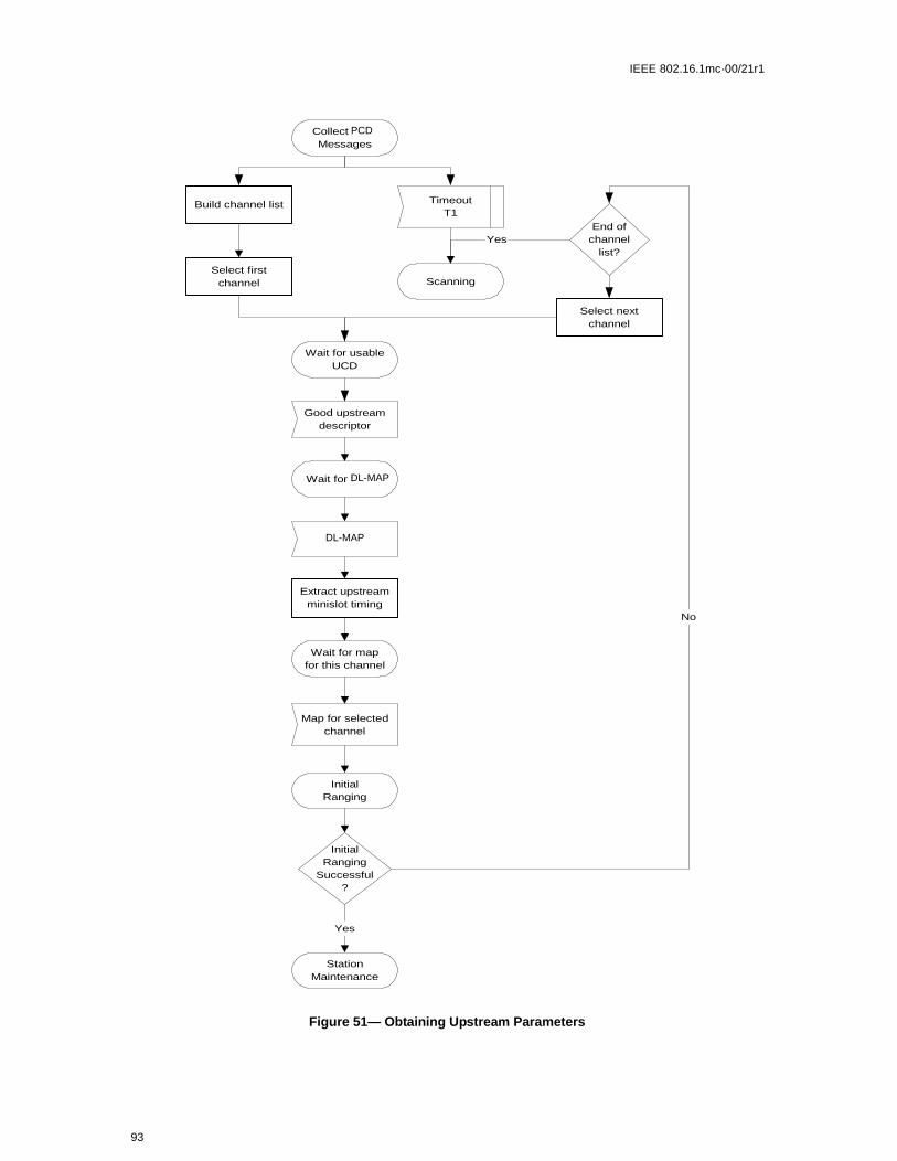
IEEE 802.16.1mc-00/21r1
Figure 51— Obtaining Upstream Parameters
Extract upstreamminislot timing
Good upstreamdescriptor
Wait for SYNC
SYNC
Wait for mapfor this channel
Map for selectedchannel
InitialRanging
InitialRanging
Successful?
StationMaintenance
TimeoutT1
Scanning
Collect UCDMessages
Wait for usableUCD
Build channel list
Select firstchannel
End ofchannel
list?
Select nextchannel
Yes
No
Yes
PCD
DL-MAP
DL-MAP
93

IEEE 802.16.1mc-00/21r1
6.8.4 message Flows During Scanning and Upstream Parameter Acquisition
The BS shall generate DS-MAP and PCD messages on the downstream at periodic intervals within theranges defined in Section 6.11. These messages are addressed to all CPEs. Refer to the following tables andfigures.
Table 13—message Flows During Scanning and Upstream Parameter Acquisition
BS CPE
clock time to send DS-MAP ----------------DS-MAP-------------------> |
clock time to send PCD ----------------PCD------------------------> |
|
clock time to send DS-MAP ----------------DS-MAP-------------------> |
| Example of a PCD cycle
| prior to CPE power-on
|
clock time to send DS-MAP ----------------DS-MAP-------------------> |
|
|
|
clock time to send DS-MAP ----------------DS-MAP-------------------> |
|
|
clock time to send DS-MAP ----------------DS-MAP------------------->
clock time to send PCD ----------------PCD---------------------->
clock time to send DS-MAP ----------------DS-MAP------------------->
power on sequence complete
clock time to send DS-MAP ----------------DS-MAP------------------->
establish PHY synchronization
& wait for PCD
clock time to send DS-MAP ----------------DS-MAP-------------------->
clock time to send DS-MAP ----------------DS-MAP-------------------->
clock time to send PCD ----------------PCD---------------------->
obtain parameters for this upstream chan-nel to use for initialization
clock time to send DS-MAP ----------------DS-MAP-------------------->
extract slot info for upstream & wait for transmit opportunity to perform ranging
clock time to send DS-MAP ----------------DS-MAP-------------------->
clock time to send US-MAP ----------------US-MAP---------------------->
start ranging process
94

IEEE 802.16.1mc-00/21r1
ions are PHYd time
cteristicsm shallnance
nd trip
e region.
E shallto thede the
equest
esponse a tempo-hall also timing
poraryith any
e tuningging Suc-normaler val-
6.8.5 Initial Ranging and Automatic Adjustments
Ranging is the process of acquiring the correct timing offset such that the CPE modem’s transmissaligned to a symbol that marks the beginning of a Mini-slot boundary. The timing delays through thelayer shall be relatively constant. Any variation in the PHY delays shall be accounted for in the guarof the upstream PHY layer overhead.
First, a CPE modem shall synchronize to the downstream and learn the upstream channel charathrough the Physical Channel Descriptor MAC management message. At this point, the CPE modescan the US-MAP message to find an Initial Maintenance Region. The BS shall make an Initial Mainteregion large enough to account for the variation in delays between any two CPEs (maximum roupropagation delay due to cell size plus maximum allowable implementation delay).
The CPE modem shall put together a Ranging Request message to be sent in an Initial MaintenancThe CID field shall be set to the non-initialized CPE value (zero).
Ranging adjusts each CPE’s timing offset such that it appears to be co-located with the BS. The CPset its initial timing offset to the amount of internal fixed delay equivalent to co-locating the CPE next BS. This amount includes delays introduced through a particular implementation, and shall includownstream PHY interleaving latency, if any.
When the Initial Maintenance transmit opportunity occurs, the CPE modem shall send the Ranging Rmessage. Thus, the CPE sends the message as if it was co-located with the BS.
Once the BS has successfully received the Ranging Request message, it shall return a Ranging Rmessage addressed to the individual CPE modem. Within the Ranging Response message shall berary CID assigned to this CPE modem until it has completed the registration process. The message scontain information on RF power level adjustment and offset frequency adjustment as well as anyoffset corrections.
The CPE modem shall now wait for an individual Station Maintenance region assigned to its temCID. It shall now transmit a Ranging Request message at this time using the temporary CID along wpower level and timing offset corrections.
The BS shall return another Ranging Response message to the CPE modem with any additional finrequired. The ranging request/response steps shall be repeated until the response contains a Rancessful notification or the BS aborts ranging. Once successfully ranged, the CPE modem shall join data traffic in the upstream. In particular, state machines and the applicability of retry counts and timues for the ranging process are defined in Table 27.
Note: The burst type to use for any transmission is defined by the Interval Usage Code (IUC). Each IUC ismapped to a burst type in the PCD message.
95

IEEE 802.16.1mc-00/21r1
The message sequence chart and flow charts on the following pages define the ranging and adjustment pro-cess which shall be followed by compliant CPEs and BS.
Note: The BS shall allow the CPE sufficient time to have processed the previous RNG-RSP (i.e., to modify thetransmitter parameters) before sending the CPE a specific ranging opportunity. This is defined as CPE RangingResponse Time in Section 6.11.
Table 14—Ranging and Automatic Adjustments Procedure
BS CPE
[time to send the Initial Maintenance oppor-tunity]
send map containing Initial Maintenance information element with a broadcast/multi-cast Connection ID
-----------US-MAP------------>
<---------RNG-REQ------- transmit ranging packet in contention mode with Connection ID parameter = 0
[receive recognizable ranging packet]
allocate temporary Connection ID
send ranging response ----------RNG-RSP------->
add temporary Connection ID to poll list store temporary Connection ID & adjust other parameters
[time to send the next map]
send map with Station Maintenance infor-mation element to modem using temporary CID
-----------US-MAP------------> recognize own temporary Connection ID in map
<---------RNG-REQ------- reply to Station Maintenance opportunity poll
send ranging response ----------RNG-RSP------->
adjust local parameters
[time to send an Initial Maintenance oppor-tunity] send map containing Initial Mainte-nance information element with a broadcast/multicast Connection ID
send periodic transmit opportunity to broad-cast address
------------US-MAP----------->
96

IEEE 802.16.1mc-00/21r1
Figure 52—Initial Ranging - CPE
Wait for broadcastmaintenanceopportunity
Wait for unicastmaintenanceopportunity
Wait forbroadcast ranging
opportunity
Error
Re-initialize MAC
Wait forRNG-RSP
Error
Re-initialize MAC
Adjust
local power
Randombackoff (Note)
Adjust localparameters per
RNG-RSP
Timeout T2
SendRNG-REQ
Timeout T3
RNG-RSP
Y
N
Map withmainten-ance
opportunity
Retriesexhausted
?
Note: Timeout T3 may occur because the RNG-REQs from multiple modemscollided. To avoid theses modems repeating the loop in lockstep, a random backoffis required. This is a backoff over the ranging window specified in the MAP. T3timeouts can also occur during multi-channel operation. On a system with multipleupstream channels, the CM MUST attempt initial ranging on every suitableupstream channel before moving to the next available downstream channel.
CPE
97

IEEE 802.16.1mc-00/21r1
1) Ranging Request is within the tolerance of the BS.
Figure 53—Initial Ranging - CPE (continued)
Timeout T4Map withMaintenance
opportunity
Error:Re-initialize MAC
SendRNG-REQ
Wait forRNG-RSP
Timeout T3 RNG-RSP
Adjust localparameters per
RNG-RSP
Success set fromCMTS?(Note 1)
Enable datatransfer
Establish IP layer
Yes
Abort Ranging setfrom CMTS?
No
Retries Exhausted?
No
Error:Re-initialize MAC
Yes
Adjust localpower
No
Error:Re-initialize MAC
Yes
Wait forStation Maintenance
opportunity
Wait forStation Maintenance
opportunity
Broadcast ranging
BS?
BS?
98

IEEE 802.16.1mc-00/21r1
Figure 54—Initial Ranging - BS
Yes
No
Wait forrecognizableRNG-REQ
RNG-REQ
Assign temporarySID
Add CM to polllist for future
maps
Send RNG-RSP(continue)
Reset retry countin poll list for this
CM
No
Wait for polledRNG-REQ
RNG-REQ
Good Enough?(Note 1)
No
RNG-REQ not
received
SendRNG-RSP(success)
Yes
No
Remove CM frompoll list
Done
SendRNG-RSP(continue)
SendRNG-RSP
(abort)
Yes
Wait for polledRNG-REQ
Remove CM frompoll list
Wait forrecognizableRNG-REQ
Yes
Retries Exhausted?
Retries Exhausted?
SID assigned tothis CM already?
Map will be sent per allocationalgorithm and pending tillcomplete. (Note 2)
Start T9
CID
CIDthis CPE already?
CPE
CPE
CPE
99

IEEE 802.16.1mc-00/21r1
testuntil
eipt) of
non-
ount in
e BS)
before
1) Means ranging is within the tolerable limits of the BS.2) RNG-REQ pending-till-complete was nonzero, the BS SHOULD hold off the station mainte-
nance opportunity accordingly unless needed, for example, to adjust the CPE’s power level. Ifopportunities are offered prior to the pending-till-complete expiry, the “good-enough” which follows receipt of a RNG-RSP shall not judge the CPE's transmit equalization pending-till-complete expires.
6.8.6 Ranging Parameter Adjustment
Adjustment of local parameters (e.g., transmit power) in a CPE as a result of the receipt (or non-recan RNG-RSP is considered to be implementation-dependent with the following restrictions:
All parameters shall be within the approved range at all times
a) Power adjustment shall start from the minimum value unless a valid power is available fromvolatile storage, in which case this shall be used as a starting point.
b) Power adjustment shall be capable of being reduced or increased by the specified amresponse to RNG-RSP messages.
c) If, during initialization, power is increased to the maximum value (without a response from thit shall wrap back to the minimum.
For multi-channel support, the CPE shall attempt initial ranging on every suitable upstream channelmoving to the next available downstream channel.
6.8.7 Initial Connection Establishment
6.8.7.1 Establish IP Connectivity
At this point, the CPE shall invoke DHCP mechanisms [RFC-2131] in order to obtain an IP address and anyother parameters needed to establish IP connectivity. The DHCP response shall contain the name of a filewhich contains further configuration parameters. Refer to Table 15.
Table 15—Establishing IP Connectivity
CPE DHCP
send DHCP request to broadcast address
----------------DHCP discover------------>
check CPE MAC address & respond
<--------------DHCP offer -----------------
choose server
----------------DHCP request-------------->
process request
<--------------DHCP response--------------
set up IP parameters from DHCP response
100

IEEE 802.16.1mc-00/21r1
e. The3] and
ion file
cy dif-ge to thequency.
CPEll for- (referll be fol-
e net-
6.8.7.2 Establish Time of Day
The CPE and BS need to have the current date and time. This is required for time-stamping logged eventswhich can be retrieved by the management system. This need not be authenticated and need only be accurateto the nearest second.
The protocol by which the time of day shall be retrieved is defined in [RFC-868]. Refer to Table 16. Therequest and response shall be transferred using UDP. The time retrieved from the server (UTC) shall be com-bined with the time offset received from the DHCP response to create the current local time
Successfully acquiring the Time of Day is not mandatory for a successful registration, but is necessary foron-going operation. The specific timeout for Time of Day Requests is implementation dependent. However,the CPE shall not exceed more than 3 Time of Day requests in any 5 minute period.
6.8.8 Transfer Operational Parameters
After DHCP is successful, the modem shall download the parameter file using TFTP, as shown in Section55. The TFTP configuration parameter server is specified by the “siaddr” field of the DHCP responsCPE shall use an adaptive timeout for TFTP based on binary exponential backoff. Refer to [RFC112[RFC2349].
The parameter fields required in the DHCP response and the format and content of the configuratshall be as defined in Section 6.13. Note that these fields are the minimum required for interoperability.
If a CPE downloads a configuration file containing an upstream channel and/or downstream frequenferent from what the CPE is currently using, the CPE shall not send a Registration Request messaBS. The CPE shall redo initial ranging using the configured upstream channel and/or downstream fre
6.8.8.1 Registration
A CPE shall be authorized to forward traffic into the network once it is initialized and configured. Theis authorized to forward traffic into the network via registration. To register with a BS, the CPE shaward its provisioned set of service flows and any other operational parameters in the configuration fileto Section 6.13) to the BS as part of a Registration Request. Figure 55 shows the procedure that shalowed by the CPE.
The configuration parameters downloaded to the CPE shall include a network access control object (see Sec-tion 6.12.1.3). If this is set to “no forwarding,” the CPE shall not forward data from attached CPE to th
Table 16—Establishing Time of Day
CPE Time Server
send request to time server
----------------time of day request------------>
process request
<--------------time of day response--------------
set up / correct time of day from response
101

IEEE 802.16.1mc-00/21r1
work, yet the CPE shall respond to network management requests. This allows the CPE to be configured in amode in which it is manageable but will not forward data.
Figure 55—Registration — CPE
Wait for Time ofDay Response
AcquireOperationalParameters
Wait for Reg-Rsp
RequestConfig File
Send Reg-Req
Time of DayRequest
Time of DayResponse
Timeout
Wait forSuccessful TFTP
Config FileReceived
Timeout
Mandatoryitems present?
CM MIC valid?
Yes
Yes
Time of Day retries areasynchronous with registration
IncrementRetry Counter
Retriesexceeded?
Scan forDownstream
Channel
No
Yes
CPE
102

IEEE 802.16.1mc-00/21r1
tications from
Once the CPE has sent a Registration Request to the BS it shall wait for a Registration Response to authorizeit to forward traffic to the network. Figure 56 shows the waiting procedure that shall be followed by theCPE.
The BS shall perform the following operations to confirm the CPE authorization (refer to Figure 57):
a) Calculate a MIC per Section 6.13 and compare it to the BS MIC included in the RegistrationRequest. If the MIC is invalid, the BS shall respond with an Authorization Failure.
b) If present, check the TFTP Server Timestamp field. If the BS detects that the time is different fromits local time by more than CPE Configuration Processing Time (refer to Table 27), the BS shallindicate authentication failure in the REG-RSP. The BS SHOULD also make a log entry stating theCPE MAC address from the message.
c) If present, check the TFTP Server Provisioned Modem Address field. If the Provisioned CPEAddress does not match the requesting CPE’s actual address, the BS shall indicate authenfailure in the REG-RSP. The BS SHOULD also make a log entry stating the CPE MAC addresthe message.
Figure 56—Wait for Registration Response — CPE
Wait for Reg-Rsp
SendReg-Req
Reg-RspTimeout T6
Response=ok?
Operational
ImplementationDependent
Retriesexhausted?
Error: Re-initializeMAC
No
Yes
Setup Service Flows &Activate Operational
Parameters
Yes
No
Wait for Reg-Rsp SendReg-Ack
Reg-Rsp
103

IEEE 802.16.1mc-00/21r1
tration
d) If the Registration Request contains Service Flow encodings, verify the availability of the Quality ofService requested in the provisioned Service Flow(s). If unable to provide the Service Flow(s), theBS shall respond with a Class of Service Failure and the appropriate Service Flow Response(s).
e) Verify the availability of any CPE Capabilities requested. If unable or unwilling to provide the CPECapability requested, the BS shall turn that Modem Capability ‘off’ (refer to 6.2.8.1).
f) Assign a Service Flow ID for each class of service supported.g) Reply to the modem in a Registration Response.h) If the Registration Request contains Service Flow encodings, the BS shall wait for a Regis
Acknowedgment as shown in Figure 58.
If timer T9 expires, the BS shall both de-assign the temporary CID from that CPE and make some provisionfor aging out that CID.
104

IEEE 802.16.1mc-00/21r1
Figure 57—Registration — BS
Waiting for Reg-Req
Reg-Req
CMTS MICValid?
Calculate MICover Reg-Req
Wait for Reg-Req
Send Reg-Rsp withResponse =
Authentication Failure
TFTP Server IP and/or Timestamp Valid?
Yes
No
Send Reg-Rsp withResponse =
Authentication Failure &Should Log Failure
No
Can the requestedservice(s) ever be
supported?
Send Reg-Rsp withResponse = Class of
Service Failure & ServiceNot Available=Reason
Permanent
No
Can the requestedservice(s) currently
be supported?
Yes
Send Reg-Rsp withResponse = Class of
Service Failure & ServiceNot Available=Reason
Temporary
No
Send Reg-Rsp withResponse = ok
Waiting for Reg-Ack
Set modemcapabilities
supported inRegRsp
Yes
CreateRequested
Services
Stop T9
BS
105

IEEE 802.16.1mc-00/21r1
6.8.8.2 Privacy Initialization
Following registration, if the CPE is provisioned to run Privacy, the CPE shall initialize Privacy operations,as described in Section 7. A CPE is provisioned to run Privacy if its configuration file includes a PrivacyConfiguration Setting (Section 6.12.3.1.1) and if the Privacy Enable parameter (Section 6.12.1.12) is set toenable.
6.8.8.3 Service IDs During CPE Initialization
After completion of the Registration process, the CPE will have been assigned Service Flow IDs (SFIDs) tomatch its provisioning. However, the CPE must complete a number of protocol transactions prior to thattime (e.g., Ranging, DHCP, etc.), and requires a temporary Connection ID in order to complete those steps.
On reception of an Initial Ranging Request, the BS shall allocate a temporary CID and assign it to the CPEfor initialization use. The BS may monitor use of this CID and restrict traffic to that needed for initialization.It shall inform the CPE of this assignment in the Ranging Response.
On receiving a Ranging Response addressed to it, the CPE shall use the assigned temporary CID for furtherinitialization transmission requests until the Registration Response is received.
On receiving a Ranging Response instruction to move to a new downstream frequency and/or upstreamchannel ID, the CPE shall consider any previously assigned temporary CID to be deassigned, and mustobtain a new temporary CID via initial ranging.
Figure 58—Registration Acknowledgment— BS
Waiting for Reg-Ack
Reg-Ack
RetriesExhausted?
DestroyServices
Wait for Reg-Ack
Waiting for Reg-Req
Timeout T7
Yes
Waiting for Reg-Req
Send Reg-Rspwith Response
= OK
No
106

IEEE 802.16.1mc-00/21r1
Rang-
It is possible that the Ranging Response may be lost after transmission by the BS. The CPE shall recover bytiming out and re-issuing its Initial Ranging Request. Since the CPE is uniquely identified by the sourceMAC address in the Ranging Request, the BS may immediately re-use the temporary CID previouslyassigned. If the BS assigns a new temporary CID, it shall make some provision for aging out the old CIDthat went unused (see Section TBD).
When assigning provisioned SFIDs on receiving a Registration Request, the BS may re-use the temporaryCID, assigning it to one of the Service Flows requested. If so, it shall continue to allow initialization mes-sages on that CID, since the Registration Response could be lost in transit. If the BS assigns all-new CIDsfor class-of-service provisioning, it shall age out the temporary CID. The aging-out shall allow sufficienttime to complete the registration process in case the Registration Response is lost in transit.
6.8.8.4 Multiple-Channel Support
In the event that more than one downstream signal is present in the system, the CPE shall operate using thebest valid downstream signal that it encounters when scanning. It will be instructed via the parameters in theconfiguration file to shift operation to different downstream and/or upstream frequencies if necessary.
Both upstream and downstream channels shall be identified where required in MAC management messagesusing channel identifiers.
6.9 Ranging
The BS shall provide each CPE a Periodic Ranging opportunity at least once every T4 seconds. The BS shallsend out Periodic Ranging opportunities at an interval sufficiently shorter than T4 that a MAP could bemissed without the CPE timing out. The size of this “subinterval” is BS dependent.
The CPE shall reinitialize its MAC layer after T4 seconds have elapsed without receiving a Periodicing opportunity.
Remote RF signal level adjustment at the CPE is performed through a periodic maintenance function usingthe RNG-REQ and RNG-RSP MAC messages. This is similar to initial ranging and is shown in Figure 59and Figure 60. On receiving a RNG-RSP, the CPE shall not transmit until the RF signal has been adjusted inaccordance with the RNG-RSP and has stabilized.
107

IEEE 802.16.1mc-00/21r1
Figure 59—Periodic Ranging - BS
Map will be sent per allocationalgorithm and pending till
complete (Note 2)
Yes
On periodic timeradd CM to poll list
for future maps
No
Wait for polledRNG-REQ
RNG-REQ
No
RNG-REQ notreceived
SendRNG-RSP(success)
Yes
Remove CM frompoll list
Done
SendRNG-RSP(continue)
SendRNG-RSP
(abort)
Yes
Wait for polledRNG-REQ
Remove CM frompoll list
Destroy SIDsassociated with
this CM
Done
No
Retries Exhausted?
Retries Exhausted? Good Enough?(Note 1)
Note 1: Means Ranging Request is within the tolerance limits of the CMTS for power and transmitequalization (if supported)Note 2: RNG-REQ pending-till-complete was nonzero, the CMTS SHOULD hold off the stationmaintenance opportunity accordingly unless needed, for example, to adjust the CM’s power level. Ifopportunities are offered prior to the pending-till-complete expiry, the "good-enough" test which followsreceiptof a RNG-RSP MUST NOT judge the CM’s transmit equalization until pending-till-complete expires.
CPE
CPE
CPE
CPE
CIDs
BS
BSCPE
CPE
108

IEEE 802.16.1mc-00/21r1
6.9.1 Downstream Modulation Management
The downstream modulation format (QPSK, 16-QAM or 64-QAM) is determined by the BS according tothe signal quality of the signal that is received by each CPE. To reduce the volume of upstream straffic, theCPE monitors the carrier to noise and interference ratio (CNIR), and compares the averaged value againstthe allowed region of operation. This region is bounded by threshold levels. If the received CNIR goes out-side of the allowed operating region, the CPE requests a change to a new modulation format using the RNG-REQ message. The BS acknowledges the reciept of the RNG-REQ message using the RNG-RSP message.
Figure 60—Periodic Ranging - CPE
SendRNG-REQ
Unicast maintenance opportunity
RNG-RSP
Operational
Error:Re-initialize MAC
Abort rangingfrom CMTS?
Timeout T4
IncrementRNG-REQ
Retry Counter
Timeout T3
RNG-REQretries exceeded?
YesYes
Adjust localparameters per
RNG-RSP
Reset RNG-REQRetry Counter;Clear T3 Timer
StartT3 Timer
StartT4 Timer
No
T3 Timerstarted?
No
Yes
Success or Continue
BS
109

IEEE 802.16.1mc-00/21r1
The RNG-RSP message contains the new CPE operating modulation format, which can be either the sameof different from the existing format.
The CPE applies an algorithm to determine its maximum operating modulation type in accordance with the16 and 64-QAM Threshold parameters as established in the RNG-RSP message. The Threshold Deltaparameter shall be applied to the two threshold points in accordance with Figure 61. The Threshold Deltaprovides a hysterisis around which the CPE applies the thresholds.
Table 17—Downstream Modulation Change Initiated from CPE
BS CPE
DS Modulation Requires Mod-ification
Receive RNG-REQ <--------- RNG-REQ ---------- Send RNG-REQ
Determine modulation type that is now appropriate
Modify modulation type within provisioned limits established for CPE
Send RNG-RSP ---------- RNG-RSP ---------> Receive RNG-RSP
Begin using new modulation type for the CPE
Figure 61—Modulation Threshold Usage
40
30
20
10
0
C/(
N+
I)
(dB
)
64-QAM Threshold + Threshold Delta
64-QAM Threshold - Threshold Delta
16-QAM Threshold + Threshold Delta
16-QAM Threshold - Threshold Delta
64-QAM Region
16-QAM Region
QPSK Region
110

IEEE 802.16.1mc-00/21r1
111

IEEE 802.16.1mc-00/21r1
112

IEEE 802.16.1mc-00/21r1
6.10 Quality of Service
This standard defines several Quality of Service (QoS) related concepts. These include:
a) Service Flow QoS Schedulingb) Dynamic Service Establishmentc) Two-Phase Activation Model
6.10.1 Theory of Operation
The various BWA protocol mechanisms described in this document can be used to support Quality of Ser-vice (QoS) for both upstream and downstream traffic through the CPE and the BS. This section provides anoverview of the QoS protocol mechanisms and their part in providing end-to-end QoS.
The requirements for Quality of Service include:
a) A configuration and registration function for pre-configuring CPE-based QoS Service Flows andtraffic parameters.
b) A signaling function for dynamically establishing QoS-enabled Service Flows and traffic parametersc) Utilization of MAC scheduling and traffic parameters for upstream Service Flows.d) Utilization of QoS traffic parameters for downstream Service Flows.e) Grouping of Service Flow properties into named Service Classes, so upper layer entities and exter-
nal applications (at both the CPE and BS) can request Service Flows with desired QoS parameters ina globally consistent way.
The principal mechanism for providing QoS is to associate packets traversing the RF MAC interface into aService Flow as identified by the Connection ID. A Service Flow is a unidirectional flow of packets that isprovided a particular Quality of Service. The CPE and BS provide this QoS according to the QoS Parame-ter Set defined for the Service Flow.
The primary purpose of the Quality of Service features defined here is to define transmission ordering andscheduling on the air interface. However, these features often need to work in conjunction with mechanismsbeyond the air interface in order to provide end-to-end QoS or to police the behavior of CPE modems.
Service Flows exist in both the upstream and downstream direction, and may exist without actually beingactivated to carry traffic. Service Flows have a 32-bit Service Flow Identifier (SFID) assigned by the BS.All Service Flows have an SFID; active Service Flows also have a 16-bit Connection Identifier (CID).
At least two Service Flows must be defined in each configuration file: one for upstream and one for down-stream service. The first upstream Service Flow describes the Primary Upstream Service Flow, and is thedefault Service Flow used for otherwise unclassified traffic and all MAC Messages. The first downstreamService Flow describes service to the Primary Downstream Service Flow. Additional Service Flowsdefined in the Configuration file create Service Flows that are provided QoS services.
6.10.2 Service Flows
A Service Flow is a MAC-layer transport service that provides unidirectional transport of packets either toupstream packets transmitted by the CPE or to downstream packets transmitted by the BS1. A Service Flowis characterized by a set of QoS Parameters such as latency, jitter, and throughput assurances. In order to
1A Service Flow, as defined here, has no direct relationship to the concept of a “flow” as defined by the IETF’s Integrated Services (int-serv) Working Group [RFC-2212]. An intserv flow is a collection of packets sharing transport-layer endpoints. Multiple intservflowscan be served by a single Service Flow.
113

IEEE 802.16.1mc-00/21r1
velope”t.
3. Thet ofuthori-
standardize operation between the CPE and BS, these attributes include details of how the CPE requestsupstream minislots and the expected behavior of the BS upstream scheduler.
A Service Flow is partially characterized by the following attributes2:
a) ServiceFlowID: exists for all service flowsb) Connection ID: mapping to a SFID only exists when the connection has admitted or active service
flow(s)c) ProvisionedQosParamSet: defines a set of QoS Parameters which appears in the configuration file
and is presented during registration. This may define the initial limit for authorizations allowed bythe authorization module. The ProvisionedQosParamSet is defined once when the Service Flow iscreated via registration.3
d) AdmittedQosParamSet: defines a set of QoS parameters for which the BS (and possibly the CPE)are reserving resources. The principal resource to be reserved is bandwidth, but this also includesany other memory or time-based resource required to subsequently activate the flow.
e) ActiveQosParamSet: defines set of QoS parameters defining the service actually being provided tothe Service Flow. Only an Active Service Flow may forward packets.
f) A Service Flow exists when the BS assigns a Service Flow ID (SFID) to it. The SFID serves as theprincipal identifier in the CPE and BS for the Service Flow. A Service Flow which exists has at leastan SFID, and an associated Direction.
g) The Authorization Module is a logical function within the BS that approves or denies every changeto QoS Parameters and Classifiers associated with a Service Flow. As such it defines an “enthat limits the possible values of the AdmittedQoSParameterSet and ActiveQoSParameterSe
The relationship between the QoS Parameter Sets is as shown in Figure 62 and Figure 6ActiveQoSParameterSet is always a subset4 of the AdmittedQoSParameterSet which is always a subsethe authorized “envelope.” In the dynamic authorization model, this envelope is determined by the A
2Some attributes are derived from the above attribute list. The Service Class Name is an attribute of the ProvisionedQoSParamSet. Theactivation state of the Service Flow is determined by the ActiveQoSParamSet. If the ActiveQoSParamSet is null then the service flow isinactive.3The ProvisionedQoSParamSet is null when a flow is created dynamically.4To say that QoS Parameter Set A is a subset of QoS Parameter Set B the following shall be true for all QoS Parameters in A and B:if (asmaller QoS parameter value indicates less resources, e.g. Maximum Traffic Rate)A is a subset of B if the parameter in A less than or equal to the same parameter in Bif (a larger QoS parameter value indicates less resources, e.g. Tolerated Grant Jitter)A is a subset of B if the parameter in A is greater than or equal to the same parameter in Bif (the QoS parameter specifies a periodic interval, e.g. Nominal Grant Interval), A is a subset of B if the parameter in A is an integer multiple of the same parameter in Bif (the QoS parameter is not quantitative, e.g. Service Flow Scheduling Type)A is a subset of B if the parameter in A is equal to the same parameter in B
114

IEEE 802.16.1mc-00/21r1
zation Module (labeled as the AuthorizedQoSParameterSet). In the provisioned authorization model, thisenvelope is determined by the ProvisionedQoSParameterSet.
Figure 62—Provisioned Authorization Model “Envelopes”
AuthQoSParamSet = ProvisionedQoSParamSet(SFID)
AdmittedQoSParamSet(SFID & CID)
ActiveQoSParamSet(SFID & Active CID)
115

IEEE 802.16.1mc-00/21r1
It is useful to think of three types of Service Flows:
a) Provisioned: this type of Service Flow is known via provisioning through the configuration file, itsAdmittedQoSParamSet and ActiveQoSParamSet are both null.
b) Admitted: this type of Service Flow has resources reserved by the BS for its AdmittedQoSParam-Set, but these parameters are not active (its ActiveQoSParamSet is null). Admitted Service Flowsmay have been provisioned or may have been signalled by some other mechanism.
c) Active: this type of Service Flow has resources committed by the BS for its QoS Parameter Set, (e.g.is actively sending MAPs containing unsolicited grants for a UGS-based service flow). ItsActiveQoSParamSet is non-null.
6.10.3 Object Model
The major objects of the architecture are represented by named rectangles in Figure 5-43. The Service Flowis the central concept of the MAC protocol. It is uniquely identified by a 32-bit Service Flow ID (SFID)assigned by the BS. Service Flows may be in either the upstream or downstream direction. Admitted ServiceFlows are mapped a 16-bit Connection ID (CID).
Outgoing user data is submitted to the MSAP by an convergence sub-layer process for transmission on theMAC interface. The information delivered to the MSAP includes the Connection Identifier identfying theconnection across which the information is delivered. The Service Flow for the connection is mapped via theConnection ID (CID).
Figure 63—Dynamic Authorization Model “Envelopes”
ProvisionedQoSParamSet(SFID)
AdmittedQoSParamSet(SFID & CID)
ActiveQoSParamSet(SFID & Active CID)
AuthQoSParamSet(BS only, not known by CPE)
116

IEEE 802.16.1mc-00/21r1
w QoSsubject to
pro-e; the
mple-g. Fornt Bsstime of
com-
exam-ervice
ly
The Service Class is an optional object that may be implemented at the BS. It is referenced by an ASCIIname which is intended for provisioning purposes. A Service Class is defined in the BS to have a particularQoS Parameter Set. The QoS Parameter Sets of a Service Flow may contain a reference to the Service ClassName as a “macro” that selects all of the QoS parameters of the Service Class. The Service FloParameter Sets may augment and even override the QoS parameter settings of the Service Class, authorization by the BS.
6.10.4 Service Classes
The Service Class serves the following purposes:
1) It allows operators, who so wish, to move the burden of configuring service flows from thevisioning server to the BS. Operators provision the modems with the Service Class Namimplementation of the name is configured at the BS. This allows operators to modify the imentation of a given service to local circumstances without changing modem provisioninexample, some scheduling parameters may need to be tweaked differently for two differeto provide the same service. As another example, service profiles could be changed by day.
2) It allows BS vendors to provide class-based-queuing if they choose, where service flowspete within their class and classes compete with each other for bandwidth.
3) It allows higher-layer protocols to create a Service Flow by its Service Class Name. For ple, telephony signaling may direct the CPE to instantiate any available Provisioned SFlow of class “G711”.
Note: The Service Class is optional: the flow scheduling specification may always be provided in full; a serviceflow may belong to no service class whatsoever. BS implementations may treat such “unclassed” flows differentfrom “classed” flows with equivalent parameters.
Any Service Flow may have its QoS Parameter Set specified in any of three ways:
Figure 64—Theory of Operation Object Model
Service Class
Service Class NameQoSParamSet
Service Flow
SFIDDirection[CID][ProvQosParamSet][AdmittedQoSParamSet][ActiveQosParamSet]
PDU
SFID[Service Class][CID][SFID]
0,1
N
117

IEEE 802.16.1mc-00/21r1
essfullyd Mes-, the BS
er Set ofparam-
eturnedistrativeame is
arametersxistingn.
le. ThisQ Mes-an admis-e Flowd or acti-
ores thesionedisionedeter Set.ate new
e initial
sages,ver mayts, and
requestset being
a CPEequestshe pol-
figura-ese are
a) By explicitly including all traffic parameters.b) By indirectly referring to a set of traffic parameters by specifying a Service Class Name.c) By specifying a Service Class Name along with modifying parameters.
The Service Class Name is “expanded” to its defined set of parameters at the time the BS succadmits the Service Flow. The Service Class expansion can be contained in the following BS-originatesages: Registration Response, DSA-REQ, DSC-REQ, DSA-RSP and DSC-RSP. In all of these casesshall include a Service Flow Encoding that includes the Service Class Name and the QoS Parametthe Service Class. If a CPE-initiated request contained any supplemental or overriding Service Flow eters, a successful response shall also include these parameters.
When a Service Class name is given in an admission or activation request, it is possible that the rQoS Parameter Set may change from activation to activation. This can happen because of adminchanges to the Service Class’ QoS Parameter Set at the BS. If the definition of a Service Class Nchanged at the BS (e.g. its associated QoS Parameter Set is modified), it has no effect on the QoS Pof existing Service Flows associated with that Service Class. A BS may initiate DSC transactions to eService Flows which reference the Service Class Name to affect the changed Service Class definitio
When a CPE uses the Service Class Name to specify the Admitted QoS Parameter Set, the expanded set ofTLV encodings of the Service Flow will be returned to the CPE in the response Message (REG-RSP, DSA-RSP, or DSC-RSP). Use of the Service Class Name later in the activation request may fail if the definition ofthe Service Class Name has changed and the new required resources are not available. Thus, the CPESHOULD explicitly request the expanded set of TLVs from the response Message in its later activationrequest.
6.10.5 Authorization
Every change to the Service Flow QoS Parameters shall be approved by an authorization moduincludes every REG-REQ or DSA-REQ Message to create a new Service Flow, and every DSC-REsage to change a QoS Parameter Set of an existing Service Flow. Such changes include requesting sion control decision (e.g. setting the AdmittedQoSParamSet) and requesting activation of a Servic(e.g. setting the ActiveQoSParameterSet). Reduction requests regarding the resources to be admittevated are also checked by the authorization module.
In the static authorization model, the authorization module receives all registration Messages, and stprovisioned status of all “deferred” Service Flows. Admission and activation requests for these proviservice flows will be permitted, as long as the Admitted QoS Parameter Set is a subset of the ProvQoS Parameter Set, and the Active QoS Parameter Set is a subset of the Admitted QoS ParamRequests to change the Provisioned QoS Parameter Set will be refused, as will requests to credynamic Service Flows. This defines a static system where all possible services are defined in thconfiguration of each CPE.
In the dynamic authorization model, the authorization module not only receives all registration Mesbut also communicates through a separate interface to an independent policy server. This policy serprovide to the authorization module advance notice of upcoming admission and activation requesspecifies the proper authorization action to be taken on those requests. Admission and activation from a CPE are then checked by the Authorization Module to ensure that the ActiveQoSParameterSrequested is a subset of the set provided by the policy server. Admission and activation requests fromthat are signalled in advance by the external policy server are permitted. Admission and activation rfrom a CPE that are not pre-signalled by the external policy server may result in a real-time query to ticy server, or may be refused.
During registration, the CPE shall send to the BS the authenticated set of TLVs derived from its contion file which defines the Provisioned QoS Parameter Set. Upon receipt and verification at the BS, th
118

IEEE 802.16.1mc-00/21r1
hat is,rovi-
ssigns auire an
a Provi-thorizedy deac-
Service The BStrationh DSC
w.
In theto-endre “acti-ompletesources
c) pre-
r-layerllowing Admitro. Later Grants-, so theguaran-e upper-
handed to the Authorization Module within the BS. The BS shall be capable of caching the Provisioned QoSParameter Set, and shall be able to use this information to authorize dynamic flows which are a subset of theProvisioned QoS Parameter Set. The BS SHOULD implement mechanisms for overriding this automatedapproval process (such as described in the dynamic authorization model). For example:
a) Deny all requests whether or not they have been pre-provisionedb) Define an internal table with a richer policy mechanism but seeded by the configuration file infor-
mationc) Refer all requests to an external policy server
6.10.6 Types of Service Flows
It useful to think about three basic types of Service Flows. This section describes these three types of ServiceFlows in more detail. However, it is important to note that there are more than just these three basic types.(Refer to Section 6.12.5.5.1)
6.10.6.1 Provisioned Service Flows
A Service Flow may be Provisioned but not immediately activated (sometimes called “deferred”). Tthe description of any such service flow in the TFTP configuration file contains an attribute which psions but defers activation and admission (refer to Section 6.12.5.5.1). During Registration, the BS aService Flow ID for such a service flow but does not reserve resources. The BS may also reqexchange with a policy module prior to admission.
As a result of external action beyond the scope of this specification, the CPE may choose to activate sioned Service Flow by passing the Service Flow ID and the associated QoS Parameter Sets. If auand resources are available, the BS shall respond by mapping the Service Flow to a CID. The BS mativate the Service Flow, but SHOULD not delete the Service Flow during the CPE registration epoch.
As a result of external action beyond the scope of this specification, the BS may choose to activate aFlow by passing the Service Flow ID as well as the CID and the associated QoS Parameter Sets.may deactivate the Service Flow, but SHOULD not delete the Service Flow during the CPE regisepoch. Such a Provisioned Service Flow may be activated and deactivated many times (througexchanges). In all cases, the original Service Flow ID shall be used when reactivating the service flo
6.10.6.2 Admitted Service Flows
This protocol supports a two-phase activation model which is often utilized in telephony applications.two-phase activation model, the resources for a “call” are first “admitted,” and then once the end-negotiation is completed (e.g. called party’s gateway generates an “off-hook” event) the resources avated.” Such a two-phase model serves the purposes a) of conserving network resources until a cend-to-end connection has been established, b) performing policy checks and admission control on reas quickly as possible, and, in particular, before informing the far end of a connection request, andventing several potential theft-of-service scenarios.
For example, if an upper layer service were using unsolicited grant service, and the addition of uppeflows could be adequately provided by increasing the Grants Per Interval QoS parameter, then the fomight be used. When the first upper-layer flow is pending, the CPE issues a DSA-Request with theGrants Per Interval parameter equal one, and the Activate Grants Per Interval parameter equal zewhen the upper-layer flow becomes active, it issues a DSC-Request with the instance of the Activateper-Interval parameter equal to one. Admission control was performed at the time of the reservationlater DSC-Request, having the Activate parameters within the range of the previous reservation, is teed to succeed. Subsequent upper-layer flows would be handled in the same way. If there were thre
119

IEEE 802.16.1mc-00/21r1
lly for it be sig-y some RSVP
w. It isay be current)
s asso-TheseService
, two-
layer flows establishing connections, with one flow already active, the Service Flow would have Admit(ted)Grants-per-Interval equal four, and Active Grants-per-Interval equal one.
An activation request of a Service Flow where the new ActiveQoSParamSet is a subset of the AdmittedQoS-ParamSet are being added shall be allowed (except in the case of catastrophic failure). An admission requestwhere the AdmittedQoSParamSet is a subset of the previous AdmittedQoSParamSet, so long as theActiveQoSParamSet remains a subset of the AdmittedQoSParameterSet, shall succeed.
A Service Flow that has resources assigned to its AdmittedQoSParamSet, but whose resources are not yetcompletely activated, is in a transient state. A timeout value shall be enforced by the BS that requires ServiceFlow activation within this period. (Refer to Section 6.12.5.5.9) If Service Flow activation is not completedwithin this interval, the assigned resources in excess of the active QoS parameters shall be released by theBS.
It is possible in some applications that a long-term reservation of resources is necessary or desirable. Forexample, placing a telephone call on hold should allow any resources in use for the call to be temporarilyallocated to other purposes, but these resources must be available for resumption of the call later. TheAdmittedQoSParamSet is maintained as “soft state” in the BS; this state shall be refreshed periodicato be maintained without the above timeout releasing the non-activated resources. This refresh maynalled with a periodic DSC-REQ Message with identical QoS Parameter Sets, or may be signalled binternal mechanism within the BS outside of the scope of this specification (e.g. by the BS monitoringrefresh Messages).
6.10.6.3 Active Service Flows
A Service Flow that has a non-NULL set of ActiveQoSParameters is said to be an Active Service Florequesting5 and being granted bandwidth for transport of data packets. An admitted Service Flow mmade active by providing an ActiveQoSParameterSet, signaling the resources actually desired at thetime. This completes the second stage of the two-phase activation model. (Refer to Section 6.10.6.2
A Service Flow may be Provisioned and immediately activated. This is the case for the Service Flowciated with the Basic CIDs. It is also typical of Service Flows for monthly subscription services, etc. Service Flows are established at registration time and shall be authorized by the BS MIC. These Flows may also be authorized by the BS authorization module.
Alternatively, a Service Flow may be created dynamically and immediately activated. In this casephase activation is skipped and the Service Flow is available for immediate use upon authorization.
6.10.7 General Operation
6.10.7.1 Static Operation
Static configuration of Service Flows uses the Registration process. A provisioning server provides the CPEwith configuration information. The CPE passes this information to the BS in a Registration Request. The
5According to its Request/Transmission Policy (refer toSection 6.12.5.6.3)
120

IEEE 802.16.1mc-00/21r1
BS adds information and replies with a Registration Response. The CPE sends a Registration Acknowledgeto complete registration.
A TFTP configuration file consists of one or more instances of Service Flow Encodings..
Service Flow Encodings contain either a full definition of service attributes (omitting defaultable items ifdesired) or a service class name. A service class name is an ASCII string which is known at the BS andwhich indirectly specifies a set of QoS Parameters. (Refer to Section 5.3.6.1.3 and C.2.2.3.4)
Note: At the time of the TFTP configuration file, Service Flow References exist as defined by the provisioningserver. Service Flow Identifiers do not yet exist because the BS is unaware of these service flow definitions.
The Registration Request packet contains Downstream Classifiers (if to be immediately activated) and allInactive Service Flows. The configuration file, and thus, the Registration Request, generally does not con-tain a Downstream Classifier if the corresponding Service Flow is requested with deferred activation. Thisallows for late binding of the Classifier when the Flow is activated.
Table 18—TFTP File Contents
Items Service FlowReference
Service FlowID
Service Flow EncodingsImmediate activation requested, upstream
1..m None Yet
Service Flow EncodingsProvisioned for later activation requested, upstream
(m+1)..n None Yet
Service Flow EncodingsImmediate activation requested, downstream
(n+1)..p None Yet
Service Flow EncodingsProvisioned for later activation requested, downstream
(p+1)..q None Yet
Figure 65—Registration Message Flow
ProvisioningServer
CM
CMTS
TFTP Configuration
Registration-Request
Registration Response
Registration-Ack
BS
CPE
121
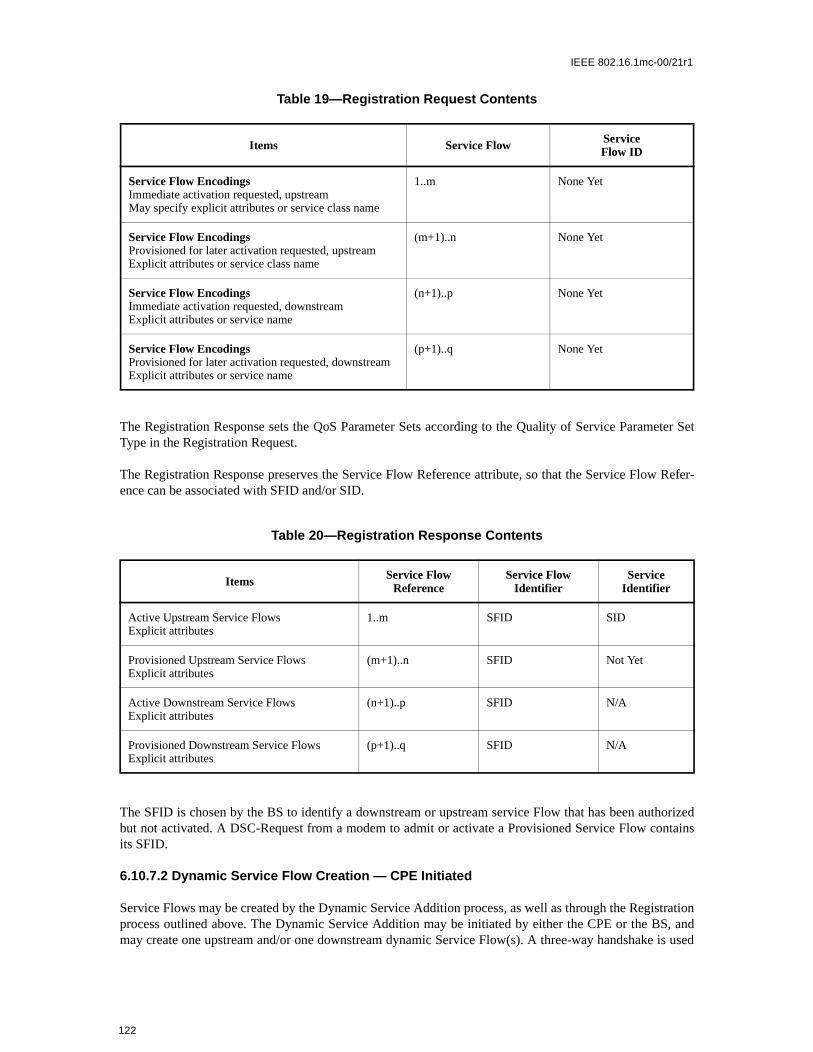
IEEE 802.16.1mc-00/21r1
The Registration Response sets the QoS Parameter Sets according to the Quality of Service Parameter SetType in the Registration Request.
The Registration Response preserves the Service Flow Reference attribute, so that the Service Flow Refer-ence can be associated with SFID and/or SID.
The SFID is chosen by the BS to identify a downstream or upstream service Flow that has been authorizedbut not activated. A DSC-Request from a modem to admit or activate a Provisioned Service Flow containsits SFID.
6.10.7.2 Dynamic Service Flow Creation — CPE Initiated
Service Flows may be created by the Dynamic Service Addition process, as well as through the Registrationprocess outlined above. The Dynamic Service Addition may be initiated by either the CPE or the BS, andmay create one upstream and/or one downstream dynamic Service Flow(s). A three-way handshake is used
Table 19—Registration Request Contents
Items Service Flow ServiceFlow ID
Service Flow EncodingsImmediate activation requested, upstreamMay specify explicit attributes or service class name
1..m None Yet
Service Flow EncodingsProvisioned for later activation requested, upstreamExplicit attributes or service class name
(m+1)..n None Yet
Service Flow EncodingsImmediate activation requested, downstreamExplicit attributes or service name
(n+1)..p None Yet
Service Flow EncodingsProvisioned for later activation requested, downstreamExplicit attributes or service name
(p+1)..q None Yet
Table 20—Registration Response Contents
Items Service FlowReference
Service FlowIdentifier
Service Identifier
Active Upstream Service FlowsExplicit attributes
1..m SFID SID
Provisioned Upstream Service FlowsExplicit attributes
(m+1)..n SFID Not Yet
Active Downstream Service FlowsExplicit attributes
(n+1)..p SFID N/A
Provisioned Downstream Service FlowsExplicit attributes
(p+1)..q SFID N/A
122

IEEE 802.16.1mc-00/21r1
tted andl and theameter
to create Service Flows. The CPE-initiated protocol is illustrated in Figure 66 and described in detail in Sec-tion 6.10.8.4.1.
A DSA-Request from a CPE contains Service Flow Reference(s), and QoS Parameter set(s) (marked either for admission-only or for admission and activation).
6.10.7.2.1 Dynamic Service Flow Creation — BS Initiated
A DSA-Request from a BS contains Service Flow Identifier(s) for one upstream and/or one downstreamService Flow, possibly a CID, and set(s) of active or admitted QoS Parameters. The protocol is as illustratedin Figure 67 and is described in detail in Section 6.10.8.4.2.
6.10.7.2.2 Dynamic Service Flow Modification and Deletion
In addition to the methods presented above for creating service flows, protocols are defined for modifyingand deleting service flows. Refer to Section 6.10.8.4 and Section 6.10.8.5.
Both provisioned and dynamically created Service flows are modified with the DSC message, which canchange the Admitted and Active QoS Parameter sets of the flow.
A successful DSC transaction changes a Service Flow’s QoS parameters by replacing both the AdmiActive QoS parameter sets. If the message contains only the Admitted set, the Active set is set to nulflow is deactivated. If the message contains neither set (‘000’ value used for Quality of Service Par
Figure 66—Dynamic Service Addition Message Flow — CPE Initiated
BS
CPE
CM
CMTS
DSA-Request
DSA-Response
DSA-Acknowledge
CPE
BS
Figure 67—Dynamic Service Addition Message Flow — BS Initiated
CM
CMTS
DSA-Request
DSA-Response
DSA-Acknowledge
CPE
BS
123

IEEE 802.16.1mc-00/21r1
Set type, see Section 6.12.5.5.1) then both sets are set to null and the flow is de-admitted. When the messagecontains both QoS parameter sets, the Admitted set is checked first and, if admission control succeeds, theActive set in the message is checked against the Admitted set in the message to ensure that it is a subse . Ifall checks are successful, the QoS parameter sets in the message become the new Admitted and Active QoSparameter sets for the Service Flow. If either of the checks fails, the DSC transaction fails and the ServiceFlow QoS parameter sets are unchanged.
6.10.8 Dynamic Service
6.10.8.1 Connection Establishment
Service Flows may be created, changed or deleted. This is accomplished through a series of MAC manage-ment Messages referred to as Dynamic Service Addition (DSA), Dynamic Service Change (DSC) andDynamic Service Deletion (DSD). The DSA Messages create a new Service Flow. The DSC Messageschange an existing Service Flow. The DSD Messages delete an existing Service Flow. This is illustrated inFigure 68.
The Null state implies that no Service Flow exists that matches the SFID and/or TransactionID in a Message.Once the Service Flow exists, it is operational and has an assigned SFID. In steady state operation, a ServiceFlow resides in a Nominal state. When Dynamic Service messaging is occurring, the Service Flow may tran-sition through other states, but remains operational. Since multiple Service Flows may exist, there may bemultiple state machines active, one for every Service Flow. Dynamic Service Messages only affect thosestate machines that match the SFID and/or Transaction ID. If privacy is enabled, both the CPE and BS shallverify the HMAC digest on all dynamic service Messages before processing them, and discard any Mes-sages that fail.
Service Flows created at registration time effectively enter the SF_operational state without a DSA transac-tion.
TransactionIDs are unique per transaction and are selected by the initiating device (CPE or BS). To help pre-vent ambiguity and provide simple checking, the TransactionID number space is split between the CPE andBS. The CPE shall select its TransactionIDs from the first half of the number space (0x0000 to 0x7FFF).The BS shall select its TransactionIDs from the second half of the number space (0x8000 to 0xFFFF).
Each dynamic service Message sequence is a unique transaction with an associated unique transaction iden-tifier. The DSA/DSC transactions consist of a request/response/acknowledge sequence. The DSD transac-tions consist of a request/response sequence. The response Messages will return a confirmation code of okayunless some exception condition was detected. The acknowledge Messages will return the confirmationcode in the response unless a new exception condition arises. A more detailed state diagram, including tran-sition states, is shown below. The detailed actions for each transaction will be given in the following sec-tions.
Figure 68—Dynamic Service Flow Overview
Null Operational
DSC
DSA
DSD
124

IEEE 802.16.1mc-00/21r1
ntedction ter-s have
ms:
6.10.8.2 Dynamic Service Flow State Transitions
The Dynamic Service Flow State Transition Diagram is the top-level state diagram and controls the generalService Flow state. As needed, it creates transactions, each represented by a Transaction state transition dia-gram, to provide the DSA, DSC, and DSD signaling. Each Transaction state transition diagram only com-municates with the parent Dynamic Service Flow State Transition Diagram. The top-level state transitiondiagram filters Dynamic Service Messages and passes them to the appropriate transaction based on ServiceFlow Identifier (SFID), Service Flow Reference number, and TransactionID.
There are six different types of transactions: locally initiated or remotely initiated for each of the DSA, DSCand DSD Messages. Most transactions have three basic states: pending, holding and deleting. The pendingstate is typically entered after creation and is where the transaction is waiting for a reply. The holding state istypically entered once the reply is received. the purpose of this state is to allow for retransmissions in case ofa lost Message, even though the local entity has perceived that the transaction has completed. The deletingstate is only entered if the Service Flow is being deleted while a transaction is being processed.
The flow diagrams provide a detailed representation of each of the states in the Transaction state transitiondiagrams. All valid transitions are shown. Any inputs not shown should be handled as a severe error condi-tion.
With one exception, these state diagrams apply equally to the BS and CPE. In the Dynamic Service FlowChanging-Local state, there is a subtle difference in the CPE and BS behaviors. This is called out in the statetransition and detailed flow diagrams.
[Note: The ‘Num Xacts’ variable in the Dynamic Service Flow State Transition Diagram is incremeevery time the top-level state diagram creates a transaction and is decremented every time a transaminates. A Dynamic Service Flow shall not return to the Null state until it’s deleted and all transactionterminated.]
The inputs for the state diagrams are identified below.
Dynamic Service Flow State Transition Diagram inputs from unspecified local, higher-level entities:
a) Addb) Changec) Delete
Dynamic Service Flow State Transition Diagram inputs from DSx Transaction State Transition diagra
a) DSA Succeededb) DSA Failedc) DSA ACK Lostd) DSA Errede) DSA Ended
a) DSC Succeededb) DSC Failedc) DSC ACK Lostd) DSC Errede) DSC Ended
125

IEEE 802.16.1mc-00/21r1
gram”
by the
ending
a) DSD Succeededb) DSD Erredc) DSD Ended
DSx Transaction State Transition diagram inputs from the Dynamic Service Flow State Transition Dia
a) SF Addb) SF Changec) SF Delete
a) SF Abort Addb) SF Change-Remotec) SF Delete-Locald) SF Delete-Remote
a) SF DSA-ACK Lostb) SF-DSC-REQ Lostc) SF-DSC-ACK Lostd) SF DSC-REQ Lost
a) SF Changedb) SF Deleted
The creation of DSx Transactions by the Dynamic Service Flow State Transition Diagram is indicatednotation
DSx-[ Local | Remote ] ( initial_input )
where initial_input may be SF Add, DSA-REQ, SF Change, DSC-REQ, SF Delete, or DSD-REQ depon the transaction type and initiator.
126

IEEE 802.16.1mc-00/21r1
Figure 69—Dynamic Service Flow State Transition Diagram
Null
AddingLocal
Add FailedAddingRemote
Nominal
ChangingLocal
ChangingRemote
Deleting
Deleted
DSA-REQ /DSA-Remote( DSA-REQ )
DSA Ended /Add / DSA-Local( SF Add )
DSA Succeeded /DSA Succeeded /
( DSA Failed / )( Delete / SF Abort Add )
DSA Failed /
DSC-REQ / SF DSA-ACK Lost
( DSC-REQ / )( DSA ACK Lost / SF DSD-REQ Lost )( DSC ACK Lost / SF DSD-REQ Lost )
( DSC-REQ / [ CMTS Only ] )( DSA ACK Lost / SF DSC-REQ Lost )( DSC ACK Lost / SF DSC-REQ Lost )
( DSD Succeeded / SF Deleted )( DSD Erred / SF Deleted )
DSD-REQ / SF Delete-Remote, DSD-Remote( DSD-REQ )
( DSC Erred / SF Delete-Local, DSD-Local( SF Delete ) )( Delete / SF Delete-Local, DSD-Local( SF Delete ) )
( DSC Erred / DSD-Local( SF Delete ) )( Delete / SF Delete-Local, DSD-Local( SF Delete ) )
Change /DSC-Local( SF Change )
( DSC Succeeded / SF Changed )( DSC Failed / SF Changed )
( DSC Succeeded / SF Changed )( DSC Failed / SF Changed )
DSC-REQ /SF Change-Remote,DSC-Remote( DSC-REQ )
DSC-REQ / SF Change-Remote,DSC-Remote( DSC-REQ ) [ CM Only ]
DSD Succeeded / SF Deleted
DSD Ended &&Num Xacts == 0 /
( DSA Erred / DSD-Local( SF Delete ) )( Delete / SF Delete-Local, DSD-Local( SF Delete ) )
New DSC-REQ /SF DSC-ACK Lost
Delete /SF Delete-Local,DSD-Local( SF Delete )
DSA Erred /DSD-Local( SF Delete )
BS
CPE
127

IEEE 802.16.1mc-00/21r1
Figure 70—DSA - Locally Initiated Transaction State Transition Diagram
Begin
End
DSA-RSPPending
( Timeout T10 / DSA Ended )( SF Changed / DSA Ended )( SF Change-Remote / DSA Ended )
Timeout T7 && Retries Exhausted /
SF Delete-Local /
( Timeout T10 / DSA Ended )( SF Deleted / DSA Ended )
DSA-RSP / DSA-ACK, DSA ACK Lost
DeletingService Flow
DSA-RSP /DSA ACK Lost
HoldingDown
SF Add / DSA-REQ
Timeout T7 && Retries Available / DSA-REQ
( DSA-RSP / DSA Succeeded, DSA-ACK )( DSA-RSP / DSA Failed, DSA-ACK )( SF Abort Add / )
RetriesExhausted ( DSA-RSP / DSA Succeeded, DSA-ACK )
( DSA-RSP / DSA Failed, DSA-ACK )( SF Abort Add / )
Timeout T10 /DSA Erred, DSA Ended
SF Delete-Remote / DSA Ended
128

IEEE 802.16.1mc-00/21r1
Figure 71—DSA - Remotely Initiated Transaction State Transition Diagram
Begin
End
( DSA-REQ / DSA-RSP )( DSA-REQ / DSA Failed, DSA-RSP )
( DSA-ACK / DSA Succeeded )( DSA-ACK / DSA Failed )
( Timeout T8 / DSA Ended )( SF Changed / DSA Ended )( SF Deleted / DSA Ended )( SF Delete-Remote / DSA Ended )
( Timeout T8 && Retries Available / DSA-RSP )( DSA-REQ && Retries Available / DSA-RSP )( DSA-REQ && Retries Exhausted / )( SF DSA-ACK Lost && Retries Available / DSA-RSP )( SF DSA-ACK Lost && Retries Exhausted / )
DSA-ACKPending
HoldingDown
SF Delete-Local /
( Timeout T10 / DSA Ended )( SF Deleted / DSA Ended )( SF Delete-Remote / DSA Ended )
( DSA-ACK / )( SF Delete-Local / )( SF Change-Remote / )
DeletingService Flow
( DSA-REQ / )( DSA-ACK / )
( Timeout T8 && Retries Exhausted / DSA Erred, DSA Ended )( SF Delete-Remote / DSA Ended )
129

IEEE 802.16.1mc-00/21r1
Figure 72—DSC - Locally Initiated Transaction State Transition Diagram
RetriesExhausted
Begin
End
SF Change / DSC-REQ
( DSC-RSP / DSC Succeeded, DSC-ACK )( DSC-RSP / DSC Failed, DSC-ACK )
( Timeout T7 && Retries Available / DSC-REQ )( SF DSC-REQ Lost && Retries Available / DSC-REQ )( SF DSC-REQ Lost && Retries Exhausted / )
DSC-RSPPending
( Timeout T10 / DSC Ended )( SF Changed / DSC Ended )( SF Change-Remote / DSC Ended )
( Timeout T10 / DSC Ended )( SF Deleted / DSC Ended )
DeletingService Flow
DSC-RSP /DSC ACK Lost
HoldingDown
SF Delete-Local /
DSC-RSP /DSC-ACK, DSC ACK Lost
SF Delete-Remote / DSC Ended
SF Change-Remote / DSC Ended [ CM Only ]
Timeout T7 && Retries Exhausted /
Timeout T10 /DSC Erred, DSC Ended
( DSC-RSP / DSC Succeeded, DSC-ACK )( DSC-RSP / DSC Failed, DSC-ACK )
CPE
130

IEEE 802.16.1mc-00/21r1
Figure 73—DSC - Remotely Initiated Transaction State Transition Diagram
Begin
End
DSC-REQ / DSC-RSP
( DSC-ACK / DSC Succeeded )( DSC-ACK / DSC Failed )
( Timeout T8 / DSC Ended )( SF Changed / DSC Ended )( SF Deleted / DSC Ended )( SF Delete-Remote / DSC Ended )
( Timeout T8 && Retries Available / DSC-RSP )( DSC-REQ && Retries Available / DSC-RSP )( DSC-REQ && Retries Exhausted / )( SF DSC-ACK Lost && Retries Available / DSC-RSP )( SF DSC-ACK Lost && Retries Exhausted / )
DSC-ACKPending
HoldingDown
SF Delete-Local /
( Timeout T10 / DSC Ended )( SF Deleted / DSC Ended )( SF Delete-Remote / DSC Ended )
( DSC-ACK / )( SF Delete-Local / )( SF Change-Remote / )
DeletingService Flow
( DSC-REQ / )( DSC-ACK / )
( Timeout T8 && Retries Exhausted / DSC Erred, DSC Ended )( SF Delete-Remote / DSC Ended )
131

IEEE 802.16.1mc-00/21r1
Figure 74—DSD - Locally Initiated Transaction State Transition Diagram
Begin
End
DSD-RSPPending
SF Delete / DSD-REQ
( Timeout T7 && Retries Available / DSD-REQ )( SF DSD-REQ Lost && Retries Available / DSD-REQ )( SF DSD-REQ Lost && Retries Exhausted / )
( DSD-RSP / DSD Succeeded )( SF Delete-Remote / )
Timeout T7 / DSD Ended
Timeout T7 && Retries Exhausted / DSD Erred, DSD EndedHoldingDown
( DSD-RSP / DSD Succeeded )( SF Deleted / )
132

IEEE 802.16.1mc-00/21r1
6.10.8.3 Dynamic Service Addition
A CPE wishing to create an upstream and/or a downstream Service Flow sends a request to the BS using adynamic service addition request Message (DSA-REQ). The BS checks the CPE’s authorization for therequested service(s) and whether the QoS requirements can be supported and generates an appropriateresponse using a dynamic service addition response Message (DSA-RSP). The CPE concludes the transac-tion with an acknowledgment Message (DSA-ACK).
Figure 75—Dynamic Deletion (DSD) - Remotely Initiated Transaction State Transition Diagram
HoldingDown
Begin
End
DSD-REQ / DSD Succeeded, DSD-RSP
( Timeout T10 / DSD Ended )( SF Deleted / DSD Ended )
DSD-REQ / DSD-RSP
133

IEEE 802.16.1mc-00/21r1
In order to facilitate a common admission response, an upstream and a downstream Service Flow can be included in a single DSA-REQ. Both Service Flows are either accepted or rejected together.
Table 21—Dynamic Service Addition Initiated from CPE
6.10.8.3.1 BS Initiated Dynamic Service Addition
A BS wishing to establish an upstream and/or a downstream dynamic Service Flow(s) with a CPE performsthe following operations. The BS checks the authorization of the destination CPE for the requested class ofservice and whether the QoS requirements can be supported. If the service can be supported the BS gener-ates new SFID(s) with the required class of service and informs the CPE using a dynamic service additionrequest Message (DSA-REQ). If the CPE checks that it can support the service and responds using a
CPE BS
New Service Flow(s) needed
Check if resources are available
Send DSA-REQ ---DSA-REQ--> Receive DSA-REQ
Check if CPE authorized for Service(s)a
aNote: authorization can happen prior to the DSA-REQ being received by the BS. The details of BS signalling to anticipatea DSA-REQ are beyond the scope of this specification.
Check Service Flow(s) QoS can be sup-ported
Create SFID(s)
If upstream AdmittedQoSParamSet is non-null, map Service Flow to CID
If upstream ActiveQoSParamSet is non-null, Enable reception of data on new upstream Service Flow
Receive DSA-RSP <--DSA-RSP--- Send DSA-RSP
If ActiveQoSParamSet is non-null, Enable transmission and/or reception of data on new Service Flow(s)
Send DSA-ACK ---DSA-ACK--> Receive DSA-ACK
If downstream ActiveQoSParamSet is non-null, Enable transmission of data on new downstream Service Flow
134

IEEE 802.16.1mc-00/21r1
C
R
C
A
Evi
S
R
EF
dynamic service addition response Message (DSA-RSP). The transaction completes with the BS sending theacknowledge Message (DSA-ACK).
Table 22—Dynamic Service Addition Initiated from BS
PE BS
New Service Flow(s) required for CPE
Check CPE authorized for Service(s)
Check Service Flow(s) QoS can be supported
Create SFID(s)
If upstream AdmittedQoSParamSet is non-null, map Service Flow to CID
If upstream ActiveQoSParamSet is non-null, Enable reception of data on new upstream ServiceFlow
eceive DSA-REQ <--DSA-REQ--- Send DSA-REQ
onfirm CPE can support Service Flow(s)
dd Downstream SFID (if present)
nable reception on any new downstream Ser-ce Flow
end DSA-RSP ---DSA-RSP--> Receive DSA-RSP
Enable transmission & reception of data on new Service Flow(s)
eceive DSA-ACK <--DSA-ACK--- Send DSA-ACK
nable transmission on new upstream Service low
135

IEEE 802.16.1mc-00/21r1
6.10.8.3.2 Dynamic Service Addition State Transition Diagrams
Figure 76—DSA - Locally Initiated Transaction Begin State Flow Diagram
SF Add
DSA-LocalBegin
Set DSA-REQRetries Availableto ’DSx Request
Retries’
DSA-REQ
Start T7 Timer
Save transmittedDSA-REQ
DSA-LocalDSA-RSPPending
136

IEEE 802.16.1mc-00/21r1
Figure 77—DSA - Locally Initiated Transaction Begin State Flow Diagram
SF Add
DSA-LocalBegin
Set DSA-REQRetries Availableto ’DSx Request
Retries’
DSA-REQ
Start T7 Timer
Save transmittedDSA-REQ
DSA-LocalDSA-RSPPending
137

IEEE 802.16.1mc-00/21r1
Figure 78—DSA - Locally Initiated Transaction DSA-RSP Pending State Flow Diagram
DSA-LocalDSA-RSPPending
DSA-RSPSF Abort Add
Stop T7 TimerStop T7 Timer
DSA Failed
Save DSA-ACKwith Condition
Code ’reject-add-aborted’
Set ConditionCode to ’reject-xxx’
Okay ?
Yes
Enableservice flow
DSASucceeded
Set ConditionCode to ’okay’
DSA-ACK
Save transmittedDSA-ACK
DSA-LocalHolding Down
Start T10 Timer
Timeout T7 SF Delete-Remote
Stop T7 Timer
DSA Ended
DSA-LocalEnd
RetriesAvailable
?
Yes
Start T10 Timer
DSA-LocalDSA-RSPPending
DSA-LocalRetries Exhausted
DecrementDSA-REQ
Retries Available
SavedDSA-REQ
Start T7 Timer
No
No
138

IEEE 802.16.1mc-00/21r1
Figure 79—DSA - Locally Initiated Transaction Holding State Flow Diagram
DSA-LocalHolding Down
Timeout T10 DSA-RSP
SavedDSA-ACK
DSA ACKLost
DSA-LocalHolding Down
SF Changed,SF Change-Remote,SF Delete-Remote
SF Delete-Local
DSA-LocalDeleting
Service FlowStop T10 Timer
DSA Ended
DSA-LocalEnd
139

IEEE 802.16.1mc-00/21r1
Figure 80—DSA - Locally Initiated Transaction Retries Exhausted State Flow Diagram
DSA-LocalRetries Exhausted
Timeout T10 SF Delete-Remote DSA-RSPSF Abort Add
DSA Failed
Save DSA-ACKwith Condition
Code ’reject-add-aborted’
Stop T10 TimerDSA Erred
DSA Ended
DSA-LocalEnd
Okay ?
Yes
Set ConditionCode to ’reject-xxx’
Set ConditionCode to ’okay’
DSA-ACK
Save transmittedDSA-ACK
DSA-LocalHolding Down
Enableservice flow
DSASucceeded
No
140

IEEE 802.16.1mc-00/21r1
Figure 81—DSA - Locally Initiated Transaction Deleting Service Flow State Flow Diagram
DSA-LocalDeleting
Service Flow
Timeout T10SF Deleted,
SF Delete-Remote
Stop T10 Timer
DSA Ended
DSA-LocalEnd
DSA-RSP
DSA ACKLost
DSA-LocalDeleting
Service Flow
141

IEEE 802.16.1mc-00/21r1
DSA-RemoteBegin
DSA-REQ
Okay ?
Yes
[ CMTS Only ]Enable
upstreamservice flow
[ CM Only ]Enable
downstreamservice flow
DSA Failed
Set ConditionCode to ’okay’
Set ConditionCode to ’reject-xxx’
DSA-RemoteDSA-ACKPending
Set DSA-RSPRetries Availableto ’DSx Response
Retries’
DSA-RSP
Start T8 Timer
Save transmittedDSA-RSP
No
Figure 82—DSA - Remotely Initiated Transaction Begin State Flow Diagram
[CPE only] [BS only]
142

IEEE 802.16.1mc-00/21r1
Figure 83—DSA - Remotely Initiated Transaction DSA-ACK Pending State Flow Diagram
DSA-RemoteDSA-ACKPending
DSA-ACK
Stop T8 Timer
Okay ?
DSA Failed
Yes
[ CMTS Only ]Enable
downstreamservice flow
[ CM Only ]Enable
upstreamservice flow
DSASucceeded
Start T8 Timer
DSA-RemoteHolding Down
Disableservice flow
SF Delete-Local
Stop T8 Timer
Start T10 Timer
DSA-RemoteDeleting
Service Flow
DSA-REQSF DSA-ACK
LostSF Delete-
Remote
Stop T8 Timer
Timeout T8
RetriesAvailable
?
Yes
DSA-RemoteDSA-ACKPending
DSA Erred
DSA-RemoteEnd
DSA Ended
DecrementDSA-RSP
Retries Available
SavedDSA-RSP
Start T8 Timer
RetriesAvailable
?
Yes
SavedDSA-RSP
No
No
No
[CPE only] [BS only]
143

IEEE 802.16.1mc-00/21r1
Figure 84—DSA - Remotely Initiated Transaction Holding Down State Flow Diagram
SF Changed,SF Deleted,
SF Delete-Remote
DSA-RemoteHolding Down
Timeout T8 DSA-ACK
DSA-RemoteHolding Down
SF Delete-Local,SF Change-Remote
Stop T8 Timer
DSA Ended
DSA-RemoteEnd
144

IEEE 802.16.1mc-00/21r1
eduling
avior is simul-
6.10.8.4 Dynamic Service Change
The Dynamic Service Change (DSC) set of Messages is used to modify the flow parameters associated witha Service Flow. Specifically, DSC can modify the Service Flow Specification.
A single DSC Message exchange can modify the parameters of one downstream service flow and/or oneupstream service flow.
To prevent packet loss, any required bandwidth change is sequenced between the CPE and BS.
The BS controls both upstream and downstream scheduling. The timing of scheduling changes is indepen-dent of direction AND whether it’s an increase or decrease in bandwidth. The BS always changes schon receipt of a DSC-REQ (CPE initiated transaction) or DSC-RSP (BS initiated transaction).
The BS also controls the downstream transmit behavior. The change in downstream transmit behalways coincident with the change in downstream scheduling (i.e. BS controls both and changes bothtaneously).
Figure 85—DSA - Remotely Initiated Transaction Deleting Service State Flow Diagram
DSA-RemoteDeleting
Service Flow
Timeout T10SF Deleted,
SF Delete-Remote
Stop T10 Timer
DSA Ended
DSA-RemoteEnd
DSA-REQ,DSA-ACK
DSA-RemoteDeleting
Service Flow
145

IEEE 802.16.1mc-00/21r1
se” in
irst andndwidthhe CPE
dwidth
C-REQever, iferefore, duringtil the
sactiontion to
sactionansac-
S shallnamic
The CPE controls the upstream transmit behavior. The timing of CPE transmit behavior changes is a func-tion of which device initiated the transaction AND whether the change is an “increase” or “decreabandwidth.
If an upstream Service Flow’s bandwidth is being reduced, the CPE reduces its payload bandwidth fthen the BS reduces the bandwidth scheduled for the Service Flow. If an upstream Service Flow’s bais being increased, the BS increases the bandwidth scheduled for the Service Flow first and then tincreases its payload bandwidth.
If the bandwidth changes are complex, it may not be obvious to the CPE when to effect the banchanges. This information may be signalled to the CPE from a higher layer entity.
Any service flow can be deactivated with a Dynamic Service Change command by sending a DSMessage, referencing the Service Flow Identifier, and including a null ActiveQoSParameterSet. Howa Primary Service Flow of a CPE is deactivated that CPE is de-registered and shall re-register. Thcare should be taken before deactivating such Service Flows. If a Service Flow that was provisionedregistration is deactivated, the provisioning information for that Service Flow shall be maintained unService Flow is reactivated.
A CPE shall have only one DSC transaction outstanding per Service Flow. If it detects a second traninitiated by the BS, the CPE shall abort the transaction it initiated and allow the BS initiated transaccomplete.
A BS shall have only one DSC transaction outstanding per Service Flow. If it detects a second traninitiated by the CPE, the BS shall abort the transaction the CPE initiated and allow the BS initiated trtion to complete.
Note: Currently anticipated applications would probably control a Service Flow through either the CPE or BS,and not both. Therefore the case of a DSC being initiated simultaneously by the CPE and BS is considered as anexception condition and treated as one.
6.10.8.4.1 CPE-Initiated Dynamic Service Change
A CPE that needs to change a Service Flow definition performs the following operations.
The CPE informs the BS using a Dynamic Service Change Request Message (DSC-REQ). The Bdecide if the referenced Service Flow can support this modification. The BS shall respond with a Dy
146

IEEE 802.16.1mc-00/21r1
Service Change Response (DSC-RSP) indicating acceptance or rejection. The CPE reconfigures the ServiceFlow if appropriate, and then shall respond with a Dynamic Service Change Acknowledge (DSC-ACK).
6.10.8.4.2 BS-Initiated Dynamic Service Change
A BS that needs to change a Service Flow definition performs the following operations.
The BS shall decide if the referenced Service Flow can support this modification. If so, the BS informs theCPE using a Dynamic Service Change Request Message (DSC-REQ). The CPE checks that it can supportthe service change, and shall respond using a Dynamic Service Change Response (DSC-RSP) indicatingacceptance or rejection. The BS reconfigures the Service Flow if appropriate, and then shall respond with aDynamic Service Change Acknowledgment (DSC-ACK)
BS CPE
Service Flow Requires Modifying
Receive DSC-REQ <--------- DSC-REQ ---------- Send DSC-REQ
Validate Request
Modify Service Flow
Increase Channel Bandwidth if Required
Send DSC-RSP ---------- DSC-RSP ---------> Receive DSC-RSP
Modify Service Flow
Adjust Payload Bandwidth
Receive DSC-ACK <--------- DSC-ACK ---------- Send DSC-ACK
Decrease Channel Bandwidth if Required
Table 23—CPE-Initiated DSC
BS CPE
Service Flow Requires Modifying
Send DSC-REQ ---------- DSC-REQ ---------> Receive DSC-REQ
Modify Service Flow
Decrease Payload Bandwidth if Required
Receive DSC-RSP <--------- DSC-RSP ---------- Send DSC-RSP
Modify Service Flow
Adjust Channel Bandwidth
Send DSC-ACK ---------- DSC-ACK ---------> Receive DSC-ACK
Increase Payload Bandwidth if Required
Table 24—BS-Initiated DSC
147

IEEE 802.16.1mc-00/21r1
6.10.8.4.3 Dynamic Service Change State Transition Diagrams
Figure 86—DSC - Locally Initiated Transaction Begin State Flow Diagram
Save service flowQoS state
DSC-LocalDSC-RSPPending
Set DSC-REQRetries Availableto ’DSx Request
Retries’
DSC-REQ
Start T7 Timer
Save transmittedDSC-REQ
[ CM Only ]If decrease upstream
bandwidth, modifytransmission
SF Change
DSC-LocalBegin
[CPE only]
148

IEEE 802.16.1mc-00/21r1
Figure 87—DSC - Locally Initiated Transaction DSC-RSP Pending State Flow Diagram
SF Delete-Local
DSC-RSP
Stop T7 Timer
Start T10 Timer
DSC-LocalDeleting
Service Flow
Stop T7 Timer
Restoreservice flowQoS state
DSC-LocalDSC-RSPPending
Okay ?
Yes
[ CMTS Only ]Modify schedule and,
if downstream,transmission
[ CM Only ]If increase upstreambandwidth, modify
transmission
SF DSC-REQLost
SF Change-Remote
[ CM Only ]
SF Delete-Remote
DSC-LocalEnd
Stop T7 Timer
DSC Ended
Timeout T7
RetriesAvailable
?
Yes
Start T10 Timer
DSC-LocalRetries Exhausted
DSC-LocalDSC-RSPPending
DecrementDSC-REQ
Retries Available
SavedDSC-REQ
Start T7 Timer
RetriesAvailable
?
Yes
SavedDSC-REQ
DSC Failed
Set ConditionCode to ’reject-xxx’
DSCSucceeded
Set ConditionCode to ’okay’
DSC-ACK
Save transmittedDSC-ACK
Start T10 Timer
DSC-LocalHolding Down
No
No
No
[CPE only] [BS only]
149

IEEE 802.16.1mc-00/21r1
Figure 88—DSC - Locally Initiated Transaction Holding Down State Flow Diagram
DSC-LocalHolding Down
Timeout T10 DSC-RSP
SavedDSC-ACK
DSC ACKLost
DSC-LocalHolding Down
SF Changed,SF Change-Remote,SF Delete-Remote
SF Delete-Local
DSC-LocalDeleting
Service FlowStop T10 Timer
DSC Ended
DSC-LocalEnd
150

IEEE 802.16.1mc-00/21r1
Figure 89—DSC - Locally Initiated Transaction Retries Exhausted State Flow Diagram
DSC-LocalRetries Exhausted
DSC-RSPSF Delete-LocalSF Delete-RemoteTimeout T10
Stop T10 TimerDSC Erred
DSC Ended
DSC-LocalEnd
DSC-LocalDeleting
Service Flow
Okay ?
[ CMTS Only ]Modify schedule
and, ifdownstream,transmission
[ CM Only ]If increaseupstream
bandwidth, modifytransmission
Set ConditionCode to ’okay’
DSC-ACK
Save transmittedDSC-ACK
DSC-LocalHolding Down
DSCSucceeded
Restoreservice flowQoS state
DSC Failed
Set ConditionCode to ’reject-xxx’
No
Yes
[CPE only] [BS only]
151

IEEE 802.16.1mc-00/21r1
Figure 90—DSC - Locally Initiated Transaction Deleting Service Flow State Flow Diagram
DSC-LocalDeleting
Service Flow
Timeout T10SF Deleted,
SF Delete-Remote
Stop T10 Timer
DSC Ended
DSC-LocalEnd
DSC-RSP
DSC ACKLost
DSC-LocalDeleting
Service Flow
152

IEEE 802.16.1mc-00/21r1
Figure 91—DSC - Remotely Initiated Transaction Begin State Flow Diagram
Okay ?
Yes
[ CMTS Only ]Modify schedule and,
if downstream,transmission
[ CM Only ]If decrease upstream
bandwidth, modifytransmission
Set ConditionCode to ’okay’
Set ConditionCode to ’reject-xxx’
DSC-RemoteDSC-ACKPending
Set DSC-RSPRetries Availableto ’DSx Response
Retries’
DSC-RSP
Start T8 Timer
Save transmittedDSC-RSP
DSC-RemoteBegin
DSC-REQ
Save service flowQoS state
No
[CPE only] [BS only]
153

IEEE 802.16.1mc-00/21r1
\
Figure 92—DSC - Remotely Initiated Transaction DSC-ACK Pending State Flow Diagram
DSC-RemoteDSC-ACKPending
SF Delete-Local
Stop T8 Timer
Start T10 Timer
DSC-RemoteDeleting
Service Flow
DSC-ACK
Stop T8 Timer
Okay ?
Yes
[ CM Only ]If increaseupstream
bandwidth, modifytransmission
Restoreservice flowQoS state
DSC FailedDSC
Succeeded
Start T8 Timer
DSC-RemoteHolding Down
DSC-REQSF DSC-ACK
LostSF Delete-
Remote
Stop T8 Timer
Timeout T8
RetriesAvailable
?
Yes
DSC-RemoteDSC-ACKPending
DSC Erred
DSC-RemoteEnd
DSC Ended
DecrementDSC-RSP
Retries Available
SavedDSC-RSP
Start T8 Timer
RetriesAvailable
?
Yes
SavedDSC-RSP
No
No
No
[CPE only]
154

IEEE 802.16.1mc-00/21r1
Figure 93—DSC - Remotely Initiated Transaction Holding Down State Flow Diagram
DSC-RemoteEnd
SF Changed,SF Deleted,
SF Delete-Remote
DSC-RemoteHolding Down
Timeout T8 DSC-ACK
DSC-RemoteHolding Down
SF Delete-Local,SF Change-Remote
Stop T8 Timer
DSC Ended
155

IEEE 802.16.1mc-00/21r1
6.10.8.5 Connection Release
Any service flow can be deleted with the Dynamic Service Deletion (DSD) Messages. When a Service Flowis deleted, all resources associated with it are released. However, if a Basic Service Flow of a CPE is deleted,that CPE is de-registered and shall re-register. Also, if a Service Flow that was provisioned during registra-tion is deleted, the provisioning information for that Service Flow is lost until the CPE re-registers. How-ever, the deletion of a provisioned Service Flow shall not cause a CPE to re-register. Therefore, care shouldbe taken before deleting such Service Flows.
Note: Unlike DSA and DSC Messages, DSD Messages are limited to only a single Service Flow.
6.10.8.5.1 CPE Initiated Dynamic Service Deletion
A CPE wishing to delete a Service Flow generates a delete request to the BS using a Dynamic Service Dele-tion-Request Message (DSD-REQ). The BS removes the Service Flow and generates a response using aDynamic Service Deletion-Response Message (DSD-RSP). Only one Service Flow can be deleted per DSD-Request.
CPE BS
Service Flow no longer needed
Delete Service Flow
Send DSD-REQ ---DSD-REQ--> Receive DSD-REQ
Figure 94—DSC - Remotely Initiated Transaction Deleting Service Flow State Flow Diagram
DSC-RemoteDeleting
Service Flow
Timeout T10SF Deleted,
SF Delete-Remote
Stop T10 Timer
DSC Ended
DSC-RemoteEnd
DSC-REQ,DSC-ACK
DSC-RemoteDeleting
Service Flow
156

IEEE 802.16.1mc-00/21r1
Table 25—Dynamic Service Deletion Initiated from CPE
6.10.8.5.2 BS Initiated Dynamic Service Deletion
A BS wishing to delete a dynamic Service Flow generates a delete request to the associated CPE using aDynamic Service Deletion-Request Message (DSD-REQ). The CPE removes the Service Flow and gener-ates a response using a Dynamic Service Deletion-Response Message (DSD-RSP). Only one Service Flowcan be deleted per DSD-Request.
Table 26—Dynamic Service Deletion Initiated from BS
Verify CPE is Service Flow ‘owner’
Delete Service Flow
Receive DSD-RSP <--DSD-RSP--- Send DSD-RSP
CPE BS
Service Flow no longer needed
Delete Service Flow
Determine associated CPE for this Service Flow
Receive DSD-REQ <---DSD-REQ--- Send DSD-REQ
Delete Service Flow
Send DSD-RSP ---DSD-RSP--> Receive DSD-RSP
157

IEEE 802.16.1mc-00/21r1
6.10.8.5.3 Dynamic Service Deletion State Transition Diagrams
Figure 95—DSD - Locally Initiated Transaction Begin State Flow Diagram
SF Delete
DSD-LocalBegin
DSD-LocalDSD-RSPPending
Set DSD-REQRetries Availableto ’DSx Request
Retries’
DSD-REQ
Start T7 Timer
Save transmittedDSD-REQ
Disableservice flow
158

IEEE 802.16.1mc-00/21r1
Figure 96—DSD - Locally Initiated Transaction DSD-RSP Pending State Flow Diagram
DSD-LocalDSD-RSPPending
DSD-RSPSF Delete-Remote
DSD-LocalHolding Down
Start T7 Timer
Stop T7 Timer Stop T7 Timer
DSDSucceeded
SF DSD-REQLost
RetriesAvailable
?
Yes
SavedDSD-REQ
Timeout T7
RetriesAvailable
?
Yes
DSD Erred
DSD Ended
DSD-LocalEnd
DSD-LocalDSD-RSPPending
DecrementDSD-REQ
Retries Available
SavedDSD-REQ
Start T7 Timer
No
No
159

IEEE 802.16.1mc-00/21r1
Figure 97—DSD - Locally Initiated Transaction Holding Down State Flow Diagram
DSD-LocalHolding Down
DSD-RSP
DSDSucceeded
DSD-LocalHolding Down
SF DeletedTimeout T7
DSD Ended
DSD-LocalEnd
160

IEEE 802.16.1mc-00/21r1
Figure 98—DSD - Remotely Initiated Transaction Begin State Flow Diagram
DSD-RemoteBegin
Start T10 Timer
Save transmittedDSD-RSP
DSD-RemoteHolding Down
Disableservice flow
DSD-REQ
DSD-RSP
DSDSucceeded
161

IEEE 802.16.1mc-00/21r1
162

IEEE 802.16.1mc-00/21r1
163

IEEE 802.16.1mc-00/21r1
164

IEEE 802.16.1mc-00/21r1
6.11 Parameters and Constants
Table 27—Parameters and Constants
System Name Time Reference Minimum Value
Default Value
Maximum Value
BS Sync Interval Nominal time between transmission of SYNC messages
200 msec
BS UCD Interval Time between transmis-sion of UCD messages
2 sec
BS Max MAP Pending The number of mini-slots that a BS is allowed to map into the future )
4096 mini-slot times
BS Ranging Interval Time between transmis-sion of broadcast Ranging requests
2 sec
CPE Lost DS-MAP Inter-val
Time since last received Sync message before syn-chronization is considered lost
600 msec
CPE Contention Ranging Retries
Number of Retries on con-tention Ranging Requests
16
CPE, BS Invited Ranging Retries
Number of Retries on inviting Ranging Requests
16
CPE Request Retries Number of retries on bandwidth allocation requests
16
CPE Registration Request Retries
Number of retries on reg-istration requests
3
CPE Data Retries Number of retries on immediate data transmis-sion
16
BS CPE UL-MAP pro-cessing time
Time provided between arrival of the last bit of a UL-MAP at a CPE and effectiveness of that MAP
200 us
BS CPE Ranging Response processing time
Minimum time allowed for a CPE following receipt of a ranging response before it is expected to reply to an invited ranging request
1 msec
BS CPE Configuration The maximum time allowed for a CPE, fol-lowing receipt of a config-uration file, to send a Registration Request to a BS.
30 sec
165

IEEE 802.16.1mc-00/21r1
CPE T1 Wait for PCD timeout 5 * PCD interval maximum value
CPE T2 Wait for broadcast ranging timeout
5 * ranging interval
CPE T3 Wait for ranging response 50 msec 200 msec 200 msec
CPE T4 Wait for unicast ranging opportunity. If the pend-ing-till-complete field was used earlier by this modem, then the value of that field must be added to this interval.
30 sec 35 sec
BS T5 Wait for Upstream Chan-nel Change response
2 sec
CPE T6 Wait for registration response
3 sec
CPE, BS Mini-slot size Size of mini-slot for upstream transmission. Must be a power of 2 (in units of the Timebase Tick)
32 symbol times
CPE, BS Timebase Tick System timing unit ¼ Symbol
CPE, BS DSx Request Retries Number of Timeout Retries on DSA/DSC/DSD Requests
3
CPE, BS DSx Response Retries Number of Timeout Retries on DSA/DSC/DSD Responses
3
CPE, BS T7 Wait for DSA/DSC/DSD Response timeout
1 sec
Table 27—Parameters and Constants
System Name Time Reference Minimum Value
Default Value
Maximum Value
166

IEEE 802.16.1mc-00/21r1
6.12 Encodings for Configuration and MAC-Layer Messaging
The following type/length/value encodings shall be used in both the configuration file (see Section 6.13), in CPE registration requests and in Dynamic Service Messages. All multi-octet quantities are in network-byte order, i.e., the octet containing the most-significant bits is the first transmitted on the wire.
The following configuration settings shall be supported by all CPEs which are compliant with this specification.
6.12.1 Configuration File and Registration Settings
These settings are found in the configuration file and, if present, shall be forwarded by the CPE to the BS in its Registration Request.
CPE, BS T8 Wait for DSA/DSC Acknowledge timeout
300 msec
CPE TFTP Backoff Start Initial value for TFTP backoff
1sec
CPE TFTP Backoff End Last value for TFTP back-off
16 sec
CPE TFTP Request Retries Number of retries on TFTP request
16
CPE TFTP Download Retries
Number of retries on entire TFTP downloads
3
CPE TFTP Wait The wait between TFTP retry sequences
10 min
CPE ToD Retries Number of Retries per ToD Retry Period
3
CPE ToD Retry Period Time period for ToD retries
5 min
BS T9 Registration Timeout, the time allowed between the BS sending a RNG-RSP (success) to a CPE, and receiving a REG-REQ from that same CPE.
15 min 15 min
CPE, BS T10 Wait for Transaction End timeout
3 sec
Table 27—Parameters and Constants
System Name Time Reference Minimum Value
Default Value
Maximum Value
167

IEEE 802.16.1mc-00/21r1
r s of not
ioning
6.12.1.1 Downstream Frequency Configuration Setting
The receive frequency to be used by the CPE. It is an override for the channel selected during scanning. This is the center frequency of the downstream channel in Hz stored as a 32-bit binary number.
Type Length Value1 4 Rx Frequency
Valid Range:The receive frequency shall be a multiple of 1000 Hz.
6.12.1.2 Upstream Channel ID Configuration Setting
The upstream channel ID which the CPE shall use. The CPE shall listen on the defined downstream channel until an upstream channel description message with this ID is found. It is an override for the channel selected during initialization.
Type Length Value2 1 Channel ID
6.12.1.3 Network Access Control Object
If the value field is a 1, Subscriber Equipment attached to this CPE are allowed access to the network, based on CPE provisioning. If the value of this field is a 0, the CPE shall not forward traffic from attached Subscriber Equipment to the MAC network, but shall continue to accept and generate traffic from the CPE itself. The value of this field does not affect BS service flow operation and does not affect BS data forwarding operation.
Type Length On / Off3 1 1 or 0
Note: The intent of “NACO = 0” is that the CPE does not forward traffic from any attached Subscribeequipment onto the BWA network. (A Subscriber is any client device attached to that CPE, regardleshow that attachment is implemented.) However, with “NACO = 0”, management traffic to the CPE is restricted. Specifically, with NACO off, the CPE remains manageable, including sending/receiving management traffic such as (but not limited to):
• ARP: allow the modem to resolve IP addresses, so it can respond to queries or send traps.
• DHCP: allow the modem to renew its IP address lease.
• ICPEP: enable network troubleshooting for tools such as “ping” and “traceroute.”
• ToD: allow the modem to continue to synchronize its clock after boot.
• TFTP: allow the modem to download either a new configuration file or a new software image.
• SYSLOG: allow the modem to report network events.
• SNMP: allow management activity
With NACO off, the primary upstream and primary downstream service flows of the CPE remain operational only for management traffic to and from the CPE. With respect to BWA provisioning, a BSshould ignore the NACO value and allocate any service flows that have been authorized by the provisserver.
168

IEEE 802.16.1mc-00/21r1
cribers’s
lt value
6.12.1.4 Downstream Modulation Configuration Setting
The allowed downstream modulation types that can be used by the CPE.
Type Length Value4 1 bit #0: QPSK
bit #1: 16-QAMbit #2: 64-QAMbit #3-7: reserved must be set to zero
6.12.1.5 CPE Message Integrity Check (MIC) Configuration Setting
The value field contains the CPE message integrity check code. This is used to detect unauthorized modification or corruption of the configuration file.
Type Length Value6 16 d1 d2....... d16
6.12.1.6 BS Message Integrity Check (MIC) Configuration Setting
The value field contains the BS message integrity check code. This is used to detect unauthorized modification or corruption of the configuration file.
Type Length Value7 16 d1 d2....... d16
6.12.1.7 Maximum Number of Subscribers
The maximum number of Subcribers that can be granted access through a CPE during a CPE epoch. The CPE epoch is the time between startup and hard reset of the modem. The maximum number of Subsshall be enforced by the CPE.
Type Length Value18 1
If present, the value shall be positive and non-zero. The non-existence of this option means the defauof 1.
Note: This is a limit on the maximum number of CPEs a CPE will grant access to. Hardware limitations of a given modem implementation may require the modem to use a lower value.
6.12.1.8 TFTP Server Timestamp
The sending time of the configuration file in seconds. The definition of time is as in [RFC-868]
Type Length Value19 4 Number of seconds since 00:00 1 Jan 1900
Note: The purpose of this parameter is to prevent replay attacks with old configuration files.
169

IEEE 802.16.1mc-00/21r1
y to side
. This low or ID
6.12.1.9 TFTP Server Provisioned CPE Address
The IP Address of the CPE requesting the configuration file.
Type Length Value20 4 IP Address
Note: The purpose of this parameter is to prevent IP spoofing during registration.
6.12.1.10 Upstream Service Flow Encodings
This field defines the parameters associated with upstream scheduling for one Service Flow. Refer to Section 6.12.5.1.
Type Length Value24 n
6.12.1.11 Downstream Service Flow Encodings
This field defines the parameters associated with downstream scheduling for one Service Flow. Refer to Section 6.12.5.2.
Type Length Value
6.12.1.12 Privacy Enable
This configuration setting enables/disables Privacy on the Primary Service Flow and all other Service Flows for this CPE.
Type Length Value29 1 0 — Disable
1 — Enable
The default value of this parameter is 1 — privacy enabled.
6.12.1.13 Vendor-Specific Information
Vendor-specific information for CPE modems, if present, shall be encoded in the vendor specific information field (VSIF) (code 43) using the Vendor ID field (6.12.3.2) to specify which TLV tuples applwhich vendors products. The Vendor ID shall be the first TLV embedded inside VSIF. If the first TLV inVSIF is not a Vendor ID, then the TLV must be discarded.
This configuration setting may appear multiple times. The same Vendor ID may appear multiple timesconfiguration setting may be nested inside a Packet Classification Configuration Setting, a Service FConfiguration Setting, or a Service Flow Response. However, there shall not be more than one VendTLV inside a single VSIF.
Type Length Value43 n per vendor definition
Example:
Configuration with vendor A specific fields and vendor B specific fields:
170

IEEE 802.16.1mc-00/21r1
of this bject
e byte
VSIF (43) + n (number of bytes inside this VSIF)8 (Vendor ID Type) + 3 (length field) + Vendor ID of Vendor AVendor A Specific Type #1 + length of the field + Value #1Vendor A Specific Type #2 + length of the field + Value #2
VSIF (43) + m (number of bytes inside this VSIF)8 (Vendor ID Type) + 3 (length field) + Vendor ID of Vendor BVendor B Specific Type + length of the field + Value
6.12.2 Configuration-File-Specific Settings
These settings are found in only the configuration file. They shall not be forwarded to the BS in the Registration Request.
6.12.2.1 End-of-Data Marker
This is a special marker for end of data.
It has no length or value fields.
Type255
6.12.2.2 Pad Configuration Setting
This has no length or value fields and is only used following the end of data marker to pad the file to an integral number of 32-bit words.
Type0
6.12.2.3 Software Upgrade Filename
The filename of the software upgrade file for the CPE. The filename is a fully qualified directory-path name. The file is expected to reside on a TFTP server identified in a configuration setting option defined in Appendix 6.12.1.9.
Type Length Value9 n filename
6.12.2.4 SNMP Write-Access Control
This object makes it possible to disable SNMP “Set” access to individual MIB objects. Each instance object controls access to all of the writeable MIB objects whose Object ID (OID) prefix matches. This omay be repeated to disable access to any number of MIB objects.
Type Length Value10 n OID prefix plus control flag
Where n is the size of the ASN.1 Basic Encoding Rules [ISO8025] encoding of the OID prefix plus onfor the control flag.
The control flag may take values:
171

IEEE 802.16.1mc-00/21r1
hall
tion
0 - allow write-access
1 - disallow write-access
Any OID prefix may be used. The Null OID 0.0 may be used to control access to all MIB objects. (The OID 1.3.6.1 will have the same effect.)
When multiple instances of this object are present and overlap, the longest (most specific) prefix has precedence. Thus, one example might be
someTabledisallow write-accesssomeTable.1.3allow write-access
This example disallows access to all objects in someTable except for someTable.1.3.
6.12.2.5 SNMP MIB Object
This object allows arbitrary SNMP MIB objects to be Set via the TFTP-Registration process.
Type Length Value11 n variable binding
where the value is an SNMP VarBind as defined in [RFC-1157]. The VarBind is encoded in ASN.1 Basic Encoding Rules, just as it would be if part of an SNMP Set request.
The CPE modem shall treat this object as if it were part of an SNMP Set Request with the following caveats:
a) It shall treat the request as fully authorized (it cannot refuse the request for lack of privilege). b) SNMP Write-Control provisions (see previous section) do not apply. c) No SNMP response is generated by the CPE.
This object may be repeated with different VarBinds to “Set” a number of MIB objects. All such Sets sbe treated as if simultaneous.
Each VarBind shall be limited to 255 bytes.
6.12.2.6 CPE Ethernet MAC Address
This object configures the CPE with the Ethernet MAC address of a CPE device. This object may berepeated to configure any number of CPE device addresses.
Type Length Value14 6 Ethernet MAC Address of CPE
6.12.2.7 Software Upgrade TFTP Server
The IP address of the TFTP server, on which the software upgrade file for the CPE resides. See Sec5.3.1.3.1.1 and Section 6.12.2.3
Type Length Value21 4 ip1,ip2,ip3,ip4
172

IEEE 802.16.1mc-00/21r1
6.12.3 Registration-Request/Response-Specific Encodings
These encodings are not found in the configuration file, but are included in the Registration Request. Some encodings are also used in the Registration Response.
The CPE shall include Modem Capabilities Encodings in its Registration Request. If present in the corresponding Registration Request, the BS shall include Modem Capabilities in the Registration Response.
6.12.3.1 Modem Capabilities Encoding
The value field describes the capabilities of a particular modem, i.e., implementation dependent limits on the particular features or number of features which the modem can support. It is composed from a number of encapsulated type/length/value fields. The encapsulated sub-types define the specific capabilities for the modem in question. Note that the sub-type fields defined are only valid within the encapsulated capabilities configuration setting string.
Type Length Value5 n
The set of possible encapsulated fields is described below.
6.12.3.1.1 Privacy Support
The value is the BPI support of the CPE.
Type Length Value5.6 1 0 Privacy Supported
1 - 255 Reserved
6.12.3.1.2 Upstream CID Support
The field shows the number of Upstream CIDs the modem can support.
Type Length Value5.8 1 Number of Upstream CIDs the CPE can support.
If the number of CIDs is 0 that means the Modem can support only 1 CID.
6.12.3.1.3 Transmit Equalizer Taps per Symbol
This field shows the maximal number of pre-equalizer taps per symbol supported by the CPE.
Note: All CPEs shall support symbol-spaced equalizer coefficients. CPE support of 2 or 4 taps per symbol is optional. If this tuple is missing, it is implied that the CPE only supports symbol spaced equalizer coefficients.
Type Length Value5.10 1 1, 2 or 4
6.12.3.1.4 Number of Transmit Equalizer Taps
This field shows the number of equalizer taps that are supported by the CPE.
173

IEEE 802.16.1mc-00/21r1
Note: All CPEs shall support an equalizer length of at least 8 symbols. CPE support of up to 64 T-spaced, T/2-spaced or T/4-spaced taps is optional. If this tuple is missing, it is implied that the CPE only supports an equalizer length of 8 taps.
Type Length Value5.11 1 8 to 64
6.12.3.1.5 CPE Demodulator Types
This field indicates the different modulation types supported by the CPE for downstream reception.
Type Length Value5.12 1 bit #0: QPSK
bit #1: 16-QAMbit #2: 64-QAMbit #3-7: reserved must be set to zero
6.12.3.1.6 CPE Modulator Types
This field indicates the different modulation types supported by the CPE for upstream transmission.
Type Length Value5.13 1 bit #0: QPSK
bit #1: 16-QAMbit #2: 64-QAMbit #3-7: reserved must be set to zero
6.12.3.1.7 Duplexing Support
This field indicates the different duplexing modes the CPE is able to support.
Type Length Value5.14 1 bit #0: FDD (continuous downstream)
bit #1: FDD (burst downstream)bit #2: Half-Duplex FDDbit #3: TDDbit #4-7: reserved must be set to zero
6.12.3.1.8 Bandwidth Allocation Support
This field indicates the different bandwidth allocation modes the CPE is able to support.
Type Length Value5.15 1 bit #0: Grant per Connection
bit #1: Grant per Terminal (CPE)bit #2-7: reserved must be set to zero
6.12.3.2 Vendor ID Encoding
The value field contains the vendor identification specified by the three-byte vendor-specific Organization Unique Identifier of the CPE MAC address.
174

IEEE 802.16.1mc-00/21r1
ormed ssage er in
rithm,
ined in in
to
The Vendor ID shall be used in a Registration Request, but shall not be used as a stand-alone configuration file element. It may be used as a sub-field of the Vendor Specific Information Field in a configuration file. When used as a sub-field of the Vendor Specific Information field, this identifies the Vendor ID of the CPEs which are intended to use this information. When the vendor ID is used in a Registration Request, then it is the Vendor ID of the CPE sending the request.
Type Length Value8 3 v1, v2, v3
6.12.3.3 Service(s) Not Available Response
This configuration setting shall be included in the Registration Response message if the BS is unable or unwilling to grant any of the requested classes of service that appeared in the Registration Request. Although the value applies only to the failed service class, the entire Registration Request shall be considered to have failed (none of the class-of-service configuration settings are granted).
Type Length Value13 3 Class ID, Type, Confirmation Code
Where
Class ID is the class-of-service class from the request which is not available
Type is the specific class-of-service object within the class which caused the request to be rejected
Confirmation Code Refer to 6.12.7.
6.12.4 Dynamic-Service-Message-Specific Encodings
These encodings are not found in the configuration file, nor in the Registration Request/Response signaling. They are only found in Dynamic Service Addition, Dynamic Service Change and Dynamic Service Deletion Request/Response messages:
6.12.4.1 HMAC-Digest
The HMAC-Digest setting is a keyed message digest. If privacy is enabled, the HMAC-Digest Attribute shall be the final Attribute in the Dynamic Service message’s Attribute list. The message digest is perfover the all of the Dynamic Service parameters (starting immediately after the MAC Management MeHeader and up to, but not including the HMAC Digest setting), other than the HMAC-Digest, in the ordwhich they appear within the packet.
Inclusion of the keyed digest allows the receiver to authenticate the message. The HMAC-Digest algoand the upstream and downstream key generation requirements are documented in Section 7.
This parameter contains a keyed hash used for message authentication. The HMAC algorithm is def[RFC2104]. The HMAC algorithm is specified using a generic cryptographic hash algorithm. BaselinePrivacy uses a particular version of HMAC that employs the Secure Hash Algorithm (SHA-1), defined[SHA].
A summary of the HMAC-Digest Attribute format is shown below. The fields are transmitted from left right.
Type Length Value27 20 A 160-bit (20 octet) keyed SHA hash
175

IEEE 802.16.1mc-00/21r1
or
single if only
s, and re.
re the es of
ewhat
share types
6.12.4.2 Authorization Block
The Authorization Block contains an authorization “hint” from the CPE to the BS. The specifics of thecontents of this “hint” are beyond the scope of this specification.
The Authorization Block may be present in CPE-initiated DSA-REQ and DSC-REQ messages. This parameter shall not be present in DSA-RSP and DSC-RSP message, nor in BS-initiated DSA-REQ nDSC-REQ messages.
The Authorization Block information applies to the entire contents of the DSC message. Thus, only aAuthorization Block may be present per DSA-REQ or DSC-REQ message. The Authorization Block, present, shall be passed to the Authorization Module in the BS. The Authorization Block information isprocessed by the Authorization Module.
Type Length Value30 n Sequence of n octets
6.12.5 Quality-of-Service-Related Encodings
The following type/length/value encodings shall be used in the configuration file, registration messageDynamic Service messages to encode parameters for Service Flows. All multi-octet quantities are innetwork-byte order, i.e., the octet containing the most-significant bits is the first transmitted on the wi
The following configuration settings shall be supported by all CPEs which are compliant with this specification.
6.12.5.1 Upstream Service Flow Encodings
This field defines the parameters associated with upstream scheduling for a Service Flow. It is somewhat complex in that is composed from a number of encapsulated type/length/value fields.
Note that the encapsulated upstream and downstream Service Flow configuration setting strings shasame subtype field numbering plan, because many of the subtype fields defined are valid for both typconfiguration settings. These type fields are not valid in other encoding contexts.
Type Length Value24 n
6.12.5.2 Downstream Service Flow Encodings
This field defines the parameters associated with downstream scheduling for a Service Flow. It is somcomplex in that is composed from a number of encapsulated type/length/value fields.
Note that the encapsulated upstream and downstream flow classification configuration setting stringsthe same subtype field numbering plan, because many of the subtype fields defined are valid for bothof configuration settings except Service Flow encodings.
Type Length Value25 n
176

IEEE 802.16.1mc-00/21r1
6.12.5.3 General Service Flow Encodings
6.12.5.3.1 Service Flow Reference
The Service Flow Reference is used to associate a packet classifier encoding with a Service Flow encoding. A Service Flow Reference is only used to establish a Service Flow ID. Once the Service Flow exists and has an assigned Service Flow ID, the Service Flow Reference shall no longer be used.
Type Length Value[24/25].1 2 1 - 65535
6.12.5.3.2 Service Flow Identifier
The Service Flow Identifier is used by the BS as the primary reference of a Service Flow. Only the BS can issue a Service Flow Identifier. It uses this parameterization to issue Service Flow Identifiers in BS-initiated DSA/DSC-Requests and in its REG/DSA/DSC-Response to CPE-initiated REG/DSA/DSC-Requests. The CPE specifies the SFID of a service flow using this parameter in a DSC-REQ message.
The configuration file shall not contain this parameter.
Type Length Value[24/25].2 4 1 - 4,294,967,295
6.12.5.3.3 Connection Identifier
The value of this field specifies the Connection Identifier assigned by the BS to a Service Flow with a non-null AdmittedQosParameterSet or ActiveQosParameterSet. This is used in the bandwidth allocation MAP to assign upstream bandwidth. This field shall be present in BS-initiated DSA-REQ or DSC-REQ message related to establishing an admitted or active upstream Service Flow. This field shall also be present in REG-RSP, DSA-RSP and DSC-RSP messages related to the successful establishment of an admitted or active upstream Service Flow.
Even though a Service Flow has been successfully admitted or activated (i.e. has an assigned Connection ID) the Service Flow ID shall be used for subsequent DSx message signalling as it is the primary handle for a service flow. If a Service Flow is no longer admitted or active (via DSC-REQ) its Connection ID may be reassigned by the BS.
SubType Length Value[24/25].3 2 CID
6.12.5.3.4 Service Class Name
The value of the field refers to a predefined BS service configuration to be used for this Service Flow.
Type Length Value[24/25].4 2 to 16 Zero-terminated string of ASCII characters.
Note: The length includes the terminating zero.
When the Service Class Name is used in a Service Flow encoding, it indicates that all the unspecified QoS Parameters of the Service Flow need to be provided by the BS. It is up to the operator to synchronize the definition of Service Class Names in the BS and in the configuration file.
177

IEEE 802.16.1mc-00/21r1
or DSC-
w ne A-RSP
Error
r
ACK, e with
sages.
a rameter
Code a given
r
6.12.5.4 Service Flow Error Encodings
This field defines the parameters associated with Service Flow Errors.
Type Length Value[24/25].5 n
A Service Flow Error Parameter Set is defined by the following individual parameters: Confirmation Code, Errored Parameter and Error Message.
The Service Flow Error Parameter Set is returned in REG-RSP, DSA-RSP and DSC-RSP messages to indicate the recipient’s response to a Service Flow establishment request in a REG-REQ, DSA-REQDSC-REQ message. The Service Flow Error Parameter Set is returned in REG-ACK, DSA-ACK andACK messages to indicate the recipient’s response to the expansion of a Service Class Name in a corresponding REG-RSP, DSA-RSP or DSC-RSP.
On failure, the sender shall include one Service Flow Error Parameter Set for each failed Service Florequested in the REG-REQ, DSA-REQ or DSC-REQ message. On failure, the sender shall include oService Flow Error Parameter Set for each failed Service Class Name expansion in the REG-RSP, DSor DSC-RSP message. Service Flow Error Parameter Set for the failed Service Flow shall include theConfirmation Code and Errored Parameter and may include an Error Message. If some Service FlowParameter Sets are rejected but other Service Flow Parameter Sets are accepted, then Service FlowParameters Sets shall be included for only the rejected Service Flow.
On success of the entire transaction, the RSP or ACK message shall not include a Service Flow ErroParameter Set.
Multiple Service Flow Error Parameter Sets may appear in a REG-RSP, DSA-RSP, DSC-RSP, REG-DSA-ACK or DSC-ACK message, since multiple Service Flow parameters may be in error. A messageven a single Service Flow Error Parameter Set shall not contain any QoS Parameters.
A Service Flow Error Parameter Set shall not appear in any REG-REQ, DSA-REQ or DSC-REQ mes
6.12.5.4.1 Errored Parameter
The value of this parameter identifies the subtype of a requested Service Flow parameter in error in rejected Service Flow request or Service Class Name expansion response. A Service Flow Error PaSet shall have exactly one Errored Parameter TLV within a given Service Flow Encoding.
Subtype Length Value[24/25].5.1 1 Service Flow Encoding Subtype in Error
6.12.5.4.2 Error Code
This parameter indicates the status of the request. A non-zero value corresponds to the Confirmationas described in 6.12.7. A Service Flow Error Parameter Set shall have exactly one Error Code within Service Flow Encoding.
Subtype Length Value[24/25].5.2 1 Confirmation code
A value of okay(0) indicates that the Service Flow request was successful. Since a Service Flow ErroParameter Set only applies to errored parameters, this value shall not be used.
178

IEEE 802.16.1mc-00/21r1
6.12.5.4.3 Error Message
This subtype is optional in a Service Flow Error Parameter Set. If present, it indicates a text string to be displayed on the CPE console and/or log that further describes a rejected Service Flow request. A Service Flow Error Parameter Set may have zero or one Error Message subtypes within a given Service Flow Encoding.
SubType Length Value[24/25].5.3 n Zero-terminated string of ASCII characters.
Note: The length N includes the terminating zero.
Note: The entire Service Flow Encoding message must have a total length of less than 256 characters.
6.12.5.5 Common Upstream and Downstream Quality-of-Service Parameter Encodings
The remaining Type 24 & 25 parameters are QoS Parameters. Any given QoS Parameter type shall appear zero or one times per Service Flow Encoding.
6.12.5.5.1 Quality of Service Parameter Set Type
This parameter shall appear within every Service flow Encoding. It specifies the proper application of the QoS Parameter Set: to the Provisioned set, the Admitted set, and/or the Active set. When two QoS Parameter Sets are the same, a multi-bit value of this parameter may be used to apply the QoS parameters to more than one set. A single message may contain multiple QoS parameter sets in separate type 24/25 Service Flow Encodings for the same Service Flow. This allows specification of the QoS Parameter Sets when their parameters are diferent. Bit 0 is the LSB of the Value field.
For every Service Flow that appears in a Registration-Request or Registration-Response message, there shall be a Service Flow Encoding that specifies a ProvisionedQoSParameterSet. This Service Flow Encoding, or other Service Flow Encoding(s), may also specify an Admitted and/or Active set.
Type Length Value[24/25].6 1 Bit # 0 Provisioned Set
Bit # 1 Admitted SetBit # 2 Active Set
Table 28—Values Used in REG-REQ and REG-RSP Messages
Table 29—Values Used In Dynamic Service Messages.
Value Messages
001 Apply to Provisioned set only
011 Apply to Provisioned and Admitted set, and perform admission control
101 Apply to Provisioned and Active sets, perform admission control, and acti-vate this Service flow
111 Apply to Provisioned, Admitted, and Active sets; perform admission control and activate this Service Flow
Value Messages
000 Sect Active and Admitted sets to Null
010 Perform admission control and apply to Admitted set
179

IEEE 802.16.1mc-00/21r1
in bits
5.5).
A BS shall handle a single update to each of the Active and Admitted QoS parameter sets. The ability to process multiple Service Flow Encodings that specify the same QoS parameter set is not required, and is left as a vendor-specific function. If a DSA/DSC contains multiple updates to a single QoS parameter set and the vendor does not support such updates, then the BS shall reply with error code 2, reject-unrecognized-configuration-setting.
6.12.5.5.2 Traffic Priority
The value of this parameter specifies the priority assigned to a Service Flow. Given two Service Flows identical in all QoS parameters besides priority, the higher priority Service Flow SHOULD be given lower delay and higher buffering preference. For otherwise non-identical Service Flows, the priority parameter SHOULD not take precedence over any conflicting Service Flow QoS parameter. The specific algorithm for enforcing this parameter is not mandated here.
For upstream service flows, the BS SHOULD use this parameter when determining precedence in request service and grant generation, and the CPE shall preferentially select contention Request opportunities for Priority Request Service IDs (refer to A.2.3) based on this priority and its Request/Transmission Policy (refer to 6.12.5.6.3).
Type Length Value[24/25].7 1 0 to 7 — Higher numbers indicate higher priority
Note: The default priority is 0.
6.12.5.5.3 Maximum Sustained Traffic Rate
This parameter is the rate parameter R of a token-bucket-based rate limit for packets. R is expressedper second, and must take into account all MAC frame data PDU of the Service Flow from the byte
following the MAC header HCS to the end of the CRC1. The number of bytes forwarded (in bytes) is limited during any time interval T by Max(T), as described in the expression
Max(T) = T * (R / 8) + B, (1)
where the parameter B (in bytes) is the Maximum Traffic Burst Configuration Setting (refer to 6.12.5.
Note: This parameter does not limit the instantaneous rate of the Service Flow.
Note: The specific algorithm for enforcing this parameter is not mandated here. Any implementation which satisfies the above equation is conformant.
Note: If this parameter is omitted or set to zero, then there is no explicitly-enforced traffic rate maximum. This field specifies only a bound, not a guarantee that this rate is available.
100 Check against Admitted set in separate Service flow Encoding, perform admission control if needed, activate this Service Flow, and apply to Active set
110 Perform admission control and activate this Service Flow, apply parameters to both Admitted and Active sets
1The payload size includes every PDU in a Concatenated MAC Frame.
Value Messages
180

IEEE 802.16.1mc-00/21r1
, up to a
ntion. is limit BS ests,
ression s (1) in
ribed in e
1522
LD be
ocate f all
6.12.5.5.4 Upstream Maximum Sustained Traffic Rate
For an upstream Service Flow, the CPE shall not request bandwidth exceeding the Max(T) requirement in (1) during any interval T because this could force the BS to fill MAPs with deferred grants.
The CPE shall defer upstream packets that violate (1) and “rate shape” them to meet the expressionlimit as implemented by vendor buffering restrictions.
The BS shall enforce expression (1) on all upstream data transmissions, including data sent in conteThe BS may consider unused grants in calculations involving this parameter. The BS may enforce thby any of the following methods: (a) discarding over-limit requests, (b) deferring (through zero-lengthgrants) the grant until it is conforming to the allowed limit, or (c) discarding over-limit data packets. Ashall report this condition to a policy module. If the BS is policing by discarding either packets or requthe BS shall allow a margin of error between the CPE and BS algorithms.
Type Length Value24.8 4 R (in bits per second)
Downstream Maximum Sustained Traffic Rate
For a downstream Service Flow, this parameter is only applicable at the BS. The BS shall enforce exp(1) on all downstream data transmissions. The BS shall not forward downstream packets that violateany interval T. The BS SHOULD “rate shape” the downstream traffic by enqueuing packets arriving inexcess of (1), and delay them until the expression can be met.
This parameter is not intended for enforcement on the CPE.
Type Length Value25.8 4 R (in bits per second)
6.12.5.5.5 Maximum Traffic Burst
The value of this parameter specifies the token bucket size B (in bytes) for this Service Flow as descexpression (1). This value is calculated from the byte following the MAC header HCS to the end of th
CRC2.
If this parameter is omitted, then the default B is 1522 bytes. The minimum value of B is the larger ofbytes or the value of Maximum Concatenated Burst Size (refer to 6.12.5.6.1).
Type Length Value[24/25].9 4 B (bytes)
Note: The specific algorithm for enforcing this parameter is not mandated here. Any implementation which satisfies the above equation is conformant.
6.12.5.5.6 Minimum Reserved Traffic Rate
This parameter specifies the minimum rate, in bits/sec, reserved for this Service Flow. The BS SHOUable to satisfy bandwidth requests for a Service Flow up to its Minimum Reserved Traffic Rate. If lessbandwidth than its Minimum Reserved Traffic Rate is requested for a Service Flow, the BS may reallthe excess reserved bandwidth for other purposes. The aggregate Minimum Reserved Traffic Rate o
2The payload size includes every PDU in a Concatenated MAC Frame.
181

IEEE 802.16.1mc-00/21r1
’s DSC-itted
Service Flows may exceed the amount of available bandwidth. This value of this parameter is calculated
from the byte following the MAC header HCS to the end of the CRC3. If this parameter is omitted, then it defaults to a value of 0 bits/sec (i.e., no bandwidth is reserved for the flow by default).
This field is only applicable at the BS and shall be enforced by the BS.
Type Length Value[24/25].10 4
Note: The specific algorithm for enforcing the value specified in this field is not mandated here.
6.12.5.5.7 Assumed Minimum Reserved Rate Packet Size
The value of this field specifies an assumed minimum packet size (in bytes) for which the Minimum Reserved Traffic Rate will be provided. This parameter is defined in bytes and is specified as the bytes
following the MAC header HCS to the end of the CRC4. If the Service Flow sends packets of a size smaller than this specified value, such packets will be treated as being of the size specified in this parameter for calculating the minimum Reserved Traffic Rate and for calculating bytes counts (e.g. bytes transmitted) which may ultimately be used for billing.
The BS shall apply this parameter to its Minimum Reserved Traffic Rate algorithm. This parameter is used by the BS to estimate the per packet overhead of each packet in the service flow.
If this parameter is omitted, then the default value is BS implementation dependent.
Type Length Value[24/25].11 2
6.12.5.5.8 Timeout for Active QoS Parameters
The value of this parameter specifies the maximum duration resources remain unused on an active Service Flow. If there is no activity on the Service Flow within this time interval, the BS shall change the active and admitted QoS Parameter Sets to null. The BS shall signal this resource change with a DSC-REQ to the CPE.
If defined, this parameter shall be enforced at the BS and SHOULD not be enforced at the CPE.
Type Length Value[24/25].12 2 seconds
The value of 0 means that the flow is of infinite duration and shall not be timed out due to inactivity. The default value is 0.
6.12.5.5.9 Timeout for Admitted QoS Parameters
The value of this parameter specifies the duration that the BS shall hold resources for a Service FlowAdmitted QoS Parameter Set while they are in excess of its Active QoS Parameter Set. If there is noREQ to activate the Admitted QoS Parameter Set within this time interval, the resources that are adm
3The payload size includes every PDU in a Concatenated MAC Frame.4The payload size includes every PDU in a Concatenated MAC Frame.
182

IEEE 802.16.1mc-00/21r1
but not activated shall be released, and only the active resources retained. The BS shall set the Admitted QoS Parameter Set equal to the Active QoS Parameter Set for the Service Flow and initiate a DSC-REQ exchange with the CPE to inform it of the change.
If this parameter is omitted, then the default value is 200 seconds. The value of 0 means that the Service Flow can remain in the admitted state for an infinite amount of time and shall not be timed out due to inactivity. However, this is subject to policy control by the BS.
This parameter shall be enforced by the BS. The BS may set the response value less than the requested value.
Type Length Value[24/25].13 2 seconds
6.12.5.5.10 Vendor Specific QoS Parameters
This allows vendors to encode vendor-specific QoS parameters. The Vendor ID shall be the first TLV embedded inside Vendor Specific QoS Parameters. If the first TLV inside Vendor Specific QoS Parameters is not a Vendor ID, then the TLV must be discarded. (Refer to 6.12.1.13)
Type Length Value[24/25].43 n
6.12.5.6 Upstream-Specific QoS Parameter Encodings
6.12.5.6.1 Maximum Concatenated Burst
The value of this parameter specifies the maximum concatenated burst (in bytes) which a Service Flow is allowed. This parameter is calculated from the FC byte of the Concatenation MAC Header to the last CRC in the concatenated MAC frame.
A value of 0 means there is no limit. The default value is 0.
This field is only applicable at the CPE. If defined, this parameter shall be enforced at the CPE.
Note: This value does not include any physical layer overhead.
Type Length Value24.14 2
Note: This applies only to concatenated bursts. It is legal and, in fact, it may be useful to set this smaller than the maximum Ethernet packet size. Of course, it is also legal to set this equal to or larger than the maximum Ethernet packet size.
6.12.5.6.2 Service Flow Scheduling Type
The value of this parameter specifies which upstream scheduling service is used for upstream transmission requests and packet transmissions. If this parameter is omitted, then the Best Effort service shall be assumed.
183

IEEE 802.16.1mc-00/21r1
ities.
sts
r Spe-
is bit
iated rides
This parameter is only applicable at the BS. If defined, this parameter shall be enforced by the BS.
Type Length Value24.15 1 0 Reserved
1 for Undefined (BS implementation-dependent5)2 for Best Effort3 for Non-Real-Time Polling Service4 for Real-Time Polling Service5 for Unsolicited Grant Service with Activity Detection6 for Unsolicited Grant Service7 through 255 are reserved for future use
6.12.5.6.3 Request/Transmission Policy
The value of this parameter specifies which IUC opportunities the CPE uses for upstream transmission requests and packet transmissions for this Service Flow, whether requests for this Service Flow may be piggybacked with data and whether data packets transmitted on this Service Flow can be concatenated, fragmented, or have their payload headers suppressed. For UGS, it also specifies how to treat packets that do not fit into the UGS grant. See section 8.2 for requirements related to settings of the bits of this parameter for each Service Flow Scheduling Type.
This parameter is required for all Service Flow Scheduling Types except Best Effort. If omitted in a Best Effort Service Flow QoS parameter Set, the default value of zero shall be used. Bit #0 is the LSB of the Value field. Bit 0 is the LSB of the Value field
Type Length Value24.16 4 Bit #0 The Service Flow shall not use “all CPEs” broadcast request opportun
Bit #1 The Service Flow shall not use Priority Request multicast request opportunities. (Refer to A.2.3)
Bit #2 The Service Flow shall not use Request/Data opportunities for RequeBit #3 The Service Flow shall not use Request/Data opportunities for DataBit #4 The Service Flow shall not piggyback requests with data.Bit #5 The Service Flow shall not concatenate data.Bit #6 The Service Flow shall not fragment dataBit #7 The Service Flow shall not suppress payload headers
Bit #86 The Service Flow shall drop packets that do not fit in the Unsolicited
Grant Size7 All other bits are reserved.
Note: Data grants include both short and long data grants.
5The specific implementation dependent scheduling service type could be defined in the 24.43 Vendocific Information Field.
6This bit only applies to Service Flows with the Unsolicited Grant Service Flow Scheduling Type, if this set on any other Service Flow Scheduling type it shall be ignored
7Packets that classify to an Unsolicited Grant Service Flow and are larger than the Grant Size assocwith that Service Flow are normally transmitted on the Primary Service Flow. This parameter overthat default behavior.
184

IEEE 802.16.1mc-00/21r1
6.12.5.6.4 Nominal Polling Interval
The value of this parameter specifies the nominal interval (in units of microseconds) between successive unicast request opportunities for this Service Flow on the upstream channel. This parameter is typically suited for Real-Time and Non-Real-Time Polling Service.
The ideal schedule for enforcing this parameter is defined by a reference time t0, with the desired
transmission times ti = t0 + i*interval. The actual poll times, t’i shall be in the range ti <= t’i <= ti + jitter, where interval is the value specified with this TLV, and jitter is Tolerated Poll Jitter. The accuracy of the ideal poll times, ti, are measured relative to the BS Master Clock used to generate timestamps (refer to Section 5.4.1.1).
This field is only applicable at the BS. If defined, this parameter shall be enforced by the BS.
Type Length Value24.17 4 µsec
6.12.5.6.5 Tolerated Poll Jitter
The values in this parameter specifies the maximum amount of time that the unicast request interval may be delayed from the nominal periodic schedule (measured in microseconds) for this Service Flow.
The ideal schedule for enforcing this parameter is defined by a reference time t0, with the desired poll times
ti = t0 + i*interval. The actual poll, t’i shall be in the range ti <= t’i <= ti + jitter, where jitter is the value specified with this TLV and interval is the Nominal Poll Interval. The accuracy of the ideal poll times, ti, are measured relative to the BS Master Clock used to generate timestamps (refer to Section 5.4.1.1).
This parameter is only applicable at the BS. If defined, this parameter represents a service commitment (or admission criteria) at the BS.
Type Length Value24.18 4 µsec
6.12.5.6.6 Unsolicited Grant Size
The value of this parameter specifies the unsolicited grant size in bytes. The grant size includes the entire MAC frame data PDU from the Frame Control byte to end of the MAC frame.
This parameter is applicable at the BS and shall be enforced at the BS.
Type Length Value24.19 2
Note: For UGS, this parameter should be used by the BS to compute the size of the unsolicited grant in minislots.
6.12.5.6.7 Nominal Grant Interval
The value of this parameter specifies the nominal interval (in units of microseconds) between successive data grant opportunities for this Service Flow. This parameter is required for Unsolicited Grant and Unsolicited Grant with Activity Detection Service Flows.
185

IEEE 802.16.1mc-00/21r1
The ideal schedule for enforcing this parameter is defined by a reference time t0, with the desired
transmission times ti = t0 + i*interval. The actual grant times, t’i shall be in the range ti <= t’i <= ti + jitter, where interval is the value specified with this TLV, and jitter is the Tolerated Grant Jitter. When an upstream Service Flow with either Unsolicited Grant or Unsolicited Grant with Activity Detection scheduling becomes active, the first grant shall define the start of this interval, i.e. the first grant shall be for an ideal transmission time, ti. When multiple grants per interval are requested, all grants shall be within this interval, thus the Nominal Grant Interval and Tolerated Grant Jitter shall be maintained by the BS for all grants in this Service Flow. The accuracy of the ideal grant times, ti, are measured relative to the BS Master Clock used to
generate timestamps (refer to Section 5.4.1.1).
This field is mandatory for Unsolicited Grant and Unsolicited Grant with Activity Detection Scheduling Types. This field is only applicable at the BS, and shall be enforced by the BS.
Type Length Value24.20 4 µsec
6.12.5.6.8 Tolerated Grant Jitter
The values in this parameter specifies the maximum amount of time that the transmission opportunities may be delayed from the nominal periodic schedule (measured in microseconds) for this Service Flow.
The ideal schedule for enforcing this parameter is defined by a reference time t0, with the desired transmission times ti = t0 + i*interval. The actual transmission opportunities, t’i shall be in the range ti <= t’i <= ti + jitter, where jitter is the value specified with this TLV and interval is the Nominal Grant Interval. The accuracy of the ideal grant times, ti, are measured relative to the BS Master Clock used to generate
timestamps (refer to Section 5.4.1.1).
This field is mandatory for Unsolicited Grant and Unsolicited Grant with Activity Detection Scheduling Types. This field is only applicable at the BS, and shall be enforced by the BS.
Type Length Value24.21 4 µsec
6.12.5.6.9 Grants per Interval
For Unsolicited Grant Service, the value of this parameter indicates the actual number of data grants per Nominal Grant Interval. For Unsolicited Grant Service with Activity Detection, the value of this parameter indicates the maximum number of Active Grants per Nominal Grant Interval. This is intended to enable the addition of sessions to an existing Unsolicited Grant Service Flow via the Dynamic Service Change mechanism, without negatively impacting existing sessions.
The ideal schedule for enforcing this parameter is defined by a reference time t0, with the desired transmission times ti = t0 + i*interval. The actual grant times, t’i shall be in the range ti <= t’i <= ti + jitter, where interval is the Nominal Grant Interval, and jitter is the Tolerated Grant Jitter. When multiple grants per interval are requested, all grants shall be within this interval, thus the Nominal Grant Interval and Tolerated Grant Jitter shall be maintained by the BS for all grants in this Service Flow.
This field is mandatory for Unsolicited Grant and Unsolicited Grant with Activity Detection Scheduling Types. This field is only applicable at the BS, and shall be enforced by the BS.
Type Length Value Valid Range24.22 1 # of grants 0-127
186

IEEE 802.16.1mc-00/21r1
6.12.5.7 Downstream-Specific QoS Parameter Encodings
6.12.5.7.1 Maximum Downstream Latency
The value of this parameter specifies the maximum latency between the reception of a packet by the BS on its NSI and the forwarding of the packet to its RF Interface.
If defined, this parameter represents a service commitment (or admission criteria) at the BS and shall be guaranteed by the BS. A BS does not have to meet this service commitment for Service Flows that exceed their minimum downstream reserved rate.
Type Length Value25.14 4 µsec
6.12.6 Privacy Configuration Settings Option
This configuration setting describes parameters which are specific to Privacy. It is composed from a number of encapsulated type/length/value fields.
Type Length Value17 (= P_CFG) n
6.12.7 Confirmation Code
The Confirmation Code (CC) provides a common way to indicate failures for Registration Response, Registration Ack, Dynamic Service Addition-Response, Dynamic Service Addition-Ack, Dynamic Service Delete-Response, Dynamic Service Change-Response and Dynamic Service Change-Ack MAC Management Messages.
Confirmation Code is one of the following:
okay / success(0)reject-other(1)reject-unrecognized-configuration-setting(2)reject-temporary / reject-resource(3)reject-permanent / reject-admin(4)reject-not-owner(5)reject-service-flow-not-found(6)reject-service-flow-exists(7)reject-required-parameter-not-present(8)reject-header-suppression(9)reject-unknown-transaction-id(10)reject-authentication-failure(11)reject-add-aborted(12)
187

IEEE 802.16.1mc-00/21r1
e f 99.2,
below:
set to
in the
CIIimal
.of the
is is
trafficor for-
tion,
n 7).
6.12.8 Convergence Sub-Layer Parameter Encodings
Configuration files will contain parameter information used by the convergence sub-layers. Each convergence sub-layer defines a set of TLV parameters that are encoded as a set of TLVs within a subindex under the type value 99. For example, convergence sub-layer “a” would define a set of TLVs using thsubtype index of 99.1. Convergence sub-layer “b” would define a set of TLVs using a subtype index oetc.
Type Length Value99 n TLV Subindex
6.13 Configuration File
6.13.1 CPE IP Addressing
6.13.1.1 DHCP Fields Used by the CPE
The following fields shall be present in the DHCP request from the CPE and shall be set as described
a) The hardware type (htype) shall be set to 1 (Ethernet).b) The hardware length (hlen) shall be set to 6.c) The client hardware address (chaddr) shall be set to the 48 bit MAC address associated with the RF
interface of the CPE.d) The “client identifier” option shall be included, with the hardware type set to 1, and the value
the same 48 bit MAC address as the chaddr field.e) The “parameter request list” option shall be included. The option codes that shall be included
list are:1) Option code 1 (Subnet Mask)2) Option code 2 (Time Offset)3) Option code 3 (Router Option)4) Option code 4 (Time Server Option)5) Option code 7 (Log Server Option)6) Option code 60 (Vendor Specific Option) — A compliant CPE shall send the following AS
coded string in Option code 60, “802.16.1:xxxxxxx”. Where xxxxx shall be the hexidecencoding of the Modem Capabilities, refer to Section 6.12.3.1.
The following fields are expected in the DHCP response returned to the CPE. The CPE shall configure itself based on the DHCP response.
a) The IP address to be used by the CPE (yiaddr).b) The IP address of the TFTP server for use in the next phase of the bootstrap process (siaddr)c) If the DHCP server is on a different network (requiring a relay agent), then the IP address
relay agent (giaddr). Note: this may differ from the IP address of the first hop router.d) The name of the CPE configuration file to be read from the TFTP server by the CPE (file).e) The subnet mask to be used by the CPE (Subnet Mask, option 1).f) The time offset of the CPE from Universal Coordinated Time (UTC) (Time Offset, option 2). Th
used by the CPE to calculate the local time for use in time-stamping error logs.g) A list of addresses of one or more routers to be used for forwarding CPE-originated IP
(Router Option, option 3). The CPE is not required to use more than one router IP address fwarding.
h) A list of [RFC-868] time-servers from which the current time may be obtained (Time Server Opoption4).
i) A list of SYSLOG servers to which logging information may be sent (Log Server Option, optio
188

IEEE 802.16.1mc-00/21r1
E’s
he
6.13.2 CPE Configuration
6.13.2.1 CPE Binary Configuration File Format
The CPE-specific configuration data shall be contained in a file which is downloaded to the CPE via TFTP. This is a binary file in the same format defined for DHCP vendor extension data [RFC-2132].
It shall consist of a number of configuration settings (1 per parameter) each of the form
Type Length Value
WhereType is a single-octet identifier which defines the parameterLength is a single octet containing the length of the value field in octets (not including type andlength fields)Value is from one to 254 octets containing the specific value for the parameter
The configuration settings shall follow each other directly in the file, which is a stream of octets (no record markers).
Configuration settings are divided into three types:
a) Standard configuration settings which shall be presentb) Standard configuration settings which may be presentc) Vendor-specific configuration settings.
CPEs shall be capable of processing all standard configuration settings. CPEs shall ignore any configuration setting present in the configuration file which it cannot interpret. To allow uniform management of CPconformant to this specification, conformant CPE’s shall support a 8192-byte configuration file at a minimum.
Authentication of the provisioning information is provided by two message integrity check (MIC) configuration settings, CPE MIC and BS MIC.
a) CPE MIC is a digest which ensures that the data sent from the provisioning server were not modifieden route. This is not an authenticated digest (it does not include any shared secret).
b) BS MIC is a digest used to authenticate the provisioning server to the BS during registration. It istaken over a number of fields one of which is a shared secret between the BS and the provisioningserver.
Use of the CPE MIC allows the BS to authenticate the provisioning data without needing to receive tentire file.
Thus the file structure is of the form shown in Figure 99:
Figure 99— Binary Configuration File Format
ConfigurationSetting 1
ConfigurationSetting 2
ConfigurationSetting n
CPE MIC BS MIC
189

IEEE 802.16.1mc-00/21r1
n
Figure
6.13.2.2 Configuration File Settings
The following configuration settings shall be included in the configuration file and shall be supported by all CPEs.
a) Network Access Configuration Settingb) CPE MIC Configuration Settingc) BS MIC Configuration Settingd) End Configuration Settinge) Upstream Service Flow Configuration Setting f) Downstream Service Flow Configuration Setting
The following configuration settings shall be included in the configuration file and shall be supported by all CPEs that support the specific Convergence Sub-layer:
a) Convergence Sub-layer Configuration Setting(s)
The following configuration settings may be included in the configuration file and if present shall be supported by all CPEs.
a) Downstream Frequency Configuration Settingb) Upstream Channel ID Configuration Settingc) Privacy Configuration Settingd) Software Upgrade Filename Configuration Settinge) SNMP Write-Access Controlf) SNMP MIB Objectg) Software Server IP Addressh) CPE Ethernet MAC Addressi) Maximum Number of CPEsj) Privacy Enable Configuration Settingk) Payload Header Suppressionl) TFTP Server Timestampm) TFTP Server Provisioned Modem Addressn) Pad Configuration Setting
The following configuration settings may be included in the configuration file and if present may be supported by a CPE.
• Vendor-Specific Configuration Settings
Note: There is a limit on the size of registration request and registration response frames (see sectio6.2.5.2). The configuration file shall not cause the CPE to BS to exceed that limit.
6.13.2.3 Configuration File Creation
The sequence of operations required to create the configuration file is as shown in Figure 100 through103.
190

IEEE 802.16.1mc-00/21r1
1) Create the type/length/value entries for all the parameters required by the CPE.
2) Calculate the CPE message integrity check (MIC) configuration setting as defined in Section6.13.2.3.1 and add to the file following the last parameter using code and length values definedfor this field.
3) Calculate the BS message integrity check (MIC) configuration setting as defined in Section6.13.3.1 and add to the file following the CPE MIC using code and length values defined forthis field.
4)
Figure 100— Create TLV Entries for Parameters Required by the CPE
type, length, value for parameter 2
type, length, value for parameter n
type, length, value for parameter 1
Figure 101— Add CPE MIC
type, length, value for parameter 2
type, length, value for parameter n
type, length, value for CM MIC
type, length, value for parameter 1
CPEtype, length, value for CPE MIC
Figure 102— Add BS MIC
type, length, value for parameter 2
type, length, value for parameter n
type, length, value for CM MIC
type, length, value for CMTS MIC
type, length, value for parameter 1
CPEtype, length, value for CPE MIC
CPEtype, length, value for BS MIC
191
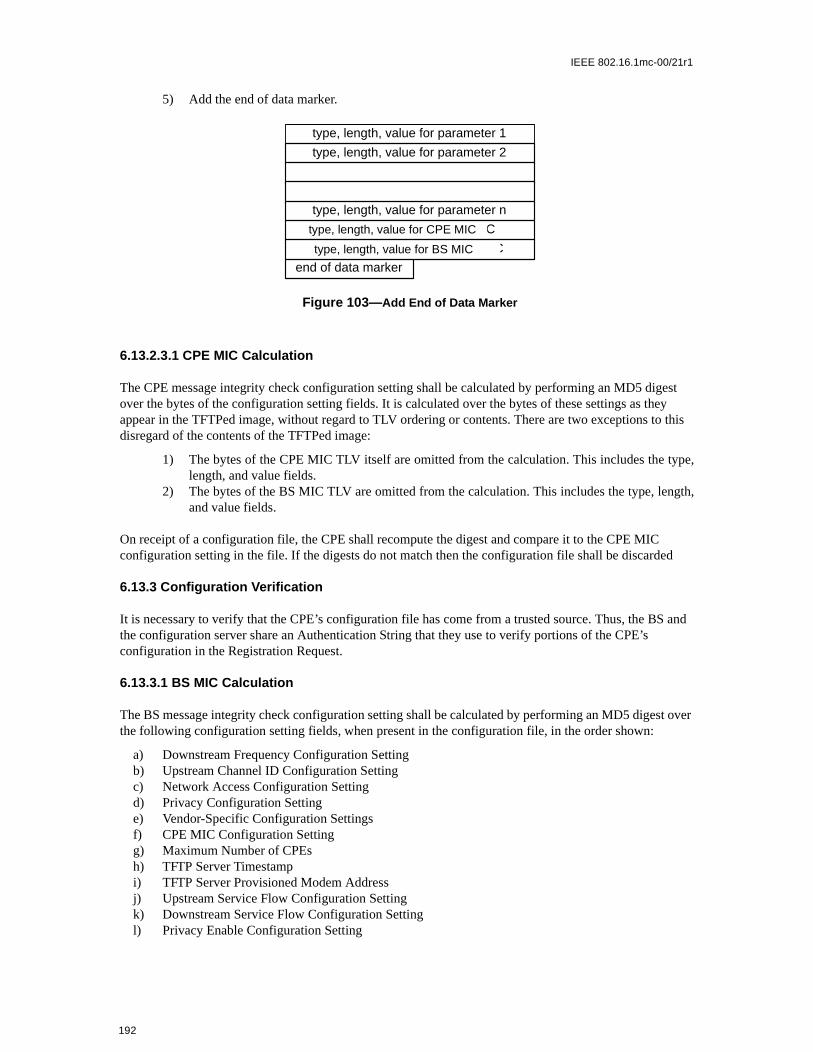
IEEE 802.16.1mc-00/21r1
S and
t over
5) Add the end of data marker.
6.13.2.3.1 CPE MIC Calculation
The CPE message integrity check configuration setting shall be calculated by performing an MD5 digest over the bytes of the configuration setting fields. It is calculated over the bytes of these settings as they appear in the TFTPed image, without regard to TLV ordering or contents. There are two exceptions to this disregard of the contents of the TFTPed image:
1) The bytes of the CPE MIC TLV itself are omitted from the calculation. This includes the type,length, and value fields.
2) The bytes of the BS MIC TLV are omitted from the calculation. This includes the type, length,and value fields.
On receipt of a configuration file, the CPE shall recompute the digest and compare it to the CPE MIC configuration setting in the file. If the digests do not match then the configuration file shall be discarded
6.13.3 Configuration Verification
It is necessary to verify that the CPE’s configuration file has come from a trusted source. Thus, the Bthe configuration server share an Authentication String that they use to verify portions of the CPE’s configuration in the Registration Request.
6.13.3.1 BS MIC Calculation
The BS message integrity check configuration setting shall be calculated by performing an MD5 digesthe following configuration setting fields, when present in the configuration file, in the order shown:
a) Downstream Frequency Configuration Settingb) Upstream Channel ID Configuration Settingc) Network Access Configuration Settingd) Privacy Configuration Settinge) Vendor-Specific Configuration Settingsf) CPE MIC Configuration Settingg) Maximum Number of CPEsh) TFTP Server Timestampi) TFTP Server Provisioned Modem Addressj) Upstream Service Flow Configuration Settingk) Downstream Service Flow Configuration Settingl) Privacy Enable Configuration Setting
Figure 103— Add End of Data Marker
type, length, value for parameter 2
type, length, value for parameter n
type, length, value for CM MIC
type, length, value for CMTS MIC
end of data marker
type, length, value for parameter 1
CPEtype, length, value for CPE MIC
CPEtype, length, value for BS MIC
192

IEEE 802.16.1mc-00/21r1
The bulleted list specifies the order of operations when calculating the BS MIC over configuration setting Type fields. The BS shall calculate the BS MIC over TLVs of the same Type in the order they were received. Within Type fields, the BS shall calculate the BS MIC over the Subtypes in the order they were received. To allow for correct BS MIC calculation by the BS, the CPE shall not reorder configuration file TLVs of the same Type or Subtypes within any given Type in its Registration-Request message.
All configuration setting fields shall be treated as if they were contiguous data when calculating the CPE MIC.
The digest shall be added to the configuration file as its own configuration setting field using the BS MIC Configuration Setting encoding.
The authentication string is a shared secret between the provisioning server (which creates the configuration files) and the BS. It allows the BS to authenticate the CPE provisioning. The authentication string is to be used as the key for calculating the keyed BS MIC digest as stated in D.3.1.1.
The mechanism by which the shared secret is managed is up to the system operator.
On receipt of a configuration file, the CPE shall forward the BS MIC as part of the registration request (REG-REQ).
On receipt of a REG-REQ, the BS shall recompute the digest over the included fields and the authentication string and compare it to the BS MIC configuration setting in the file. If the digests do not match, the registration request shall be rejected by setting the authentication failure result in the registration response status field.
6.13.3.1.1 Digest Calculation
The BS MIC digest field shall be calculated using HMAC-MD5 as defined in [RFC-2104].
193

IEEE 802.16.1mc-00/21r1
194

IEEE 802.16.1mc-00/21r1
ribu-nchro-etwork
ation
CBC) DES sup-ith data
d. Alll opera-
m the09 digi-iple
lient”,al CPE
7. Authentication and Privacy
7.1 Privacy Plus Overview
Privacy provides subscribers with privacy across the fixed broadband wireless network. It does this byencrypting connectionss between CPE and BS.
In addition, Privacy provides operators with strong protection from theft of service. The BS protects againstunauthorized access to these data transport services by enforcing encryption of the associated traffic flowsacross the network. Privacy employs an authenticated client/server key management protocol in which theBS, the server, controls distribution of keying material to client CPE. Additionally, the basic privacy mecha-nisms are strengthened by adding digital-certificate based CPE authentication to its key management proto-col.
7.1.1 Architectural Overview
Privacy has two component protocols:
a) An encapsulation protocol for encrypting packet data across the fixed broadband wireless accessnetwork. This protocol defines (1) a set of supported cryptographic suites, i.e., pairings of dataencryption and authentication algorithms, and (2) the rules for applying those algorithms to a MACheader’s payload.
b) A key management protocol (Privacy Key Management, or “PKM”) providing the secure disttion of keying data from BS to CPE. Through this key management protocol, CPE and BS synize keying data; in addition, the BS uses the protocol to enforce conditional access to nservices.
7.1.1.1 Packet Data Encryption
Encryption services are defined as a set of capabilities within the MAC sublayer. MAC Header informspecific to encryption is allocated in the Generic MAC Header Formant.
This specification supports a single packet date encryption algorithm: the Cipher Block Chaining (mode of the US Data Encryption Standard (DES) algorithm [FIPS-46-1] [FIPS-81]. It does not pairCBC with any packet data authentication algorithm. Additional data encryption algorithms may beported in future enhancements to the protocol specification, and these algorithms may be paired wauthentication algorithms.
Encryption is always applied to the MAC PDU payload; the Generic MAC Header is not encrypteMAC management messages shall be sent in the clear to facilitate registration, ranging, and normation of the MAC sublayer.
Section 7.2 specifies the format of MAC PDUs carrying encrypted packet data payloads.
7.1.1.2 Key Management Protocol
CPE use the Privacy Key Management protocol to obtain authorization and traffic keying material froBS, and to support periodic reauthorization and key refresh. The key management protocol uses X.5tal certificates [ITU1], RSA [RSA, RSA1, RSA3] (a public-key encryption algorithm) and two-key trDES to secure key exchanges between CPE and BS.
The Privacy Key Management protocol adheres to a client/server model, where the CPE, a PKM “crequests keying material, and the BS, a PKM “server”, responds to those requests, ensuring individu
195

IEEE 802.16.1mc-00/21r1
c KeyWhendigital sends
vices that authen-orized
ng fake
neratee CPEh fac-ternal-issued
re inons areate BS.on and
tors.ticationarticu-ecurityn algo-
ll of and the unicast
clients only receive keying material they are authorized for. The PKM protocol uses MAC managementmessaging.
Privacy uses public-key cryptography to establish a shared secret (i.e., an Authorization Key) between CPEand BS. The shared secret is then used to secure subsequent PKM exchanges of traffic encryption keys. Thistwo-tiered mechanism for key distribution permits refreshing of traffic encryption keys without incurring theoverhead of computation-intensive public-key operations.
A BS authenticates a client CPE during the initial authorization exchange. Each CPE carries a unique X.509digital certificate issued by the CPE’s manufacturer. The digital certificate contains the CPE’s Publialong with other identifying information; i.e., CPE MAC address, manufacturer ID and serial number. requesting an Authorization Key, a CPE presents it’s digital certificate to a BS. The BS verifies the certificate, and then uses the verified Public Key to encrypt an Authorization Key, which the BS thenback to the requesting CPE.
The BS associates a CPE’s authenticated identity to a paying subscriber, and hence to the data sersubscriber is authorized to access. Thus, with the Authorization Key exchange, the BS establishes anticated identity of a client CPE, and the services (i.e., specific traffic encryption keys) the CPE is authto access.
Since the BS authenticates CPE, it can protect against an attacker employing a cloned CPE, masquerading asa legitimate subscriber’s CPE. The use of the X.509 certificates prevents cloned CPEs from passicredentials onto a BS.
CPE shall have factory-installed RSA private/public key pairs or provide an internal algorithm to gesuch key pairs dynamically. If a CPE relies on an internal algorithm to generate its RSA key pair, thshall generate the key pair prior to its first Privacy initialization, described in Section 7.1.2.1. CPE wittory-installed RSA key pairs shall also have factory-installed X.509 certificates. CPE that rely on inalgorithms to generate an RSA key pair shall support a mechanism for installing a manufacturerX.509 certificate following key generation.
The PKM protocol is defined in detail in Section 7.5.
7.1.1.3 Security Associations
A Security Association (SA) is the set of security information a BS and one or more of its client CPE shaorder to support secure communications across the BWA network. Three types of Security Associatidefined: Primary, Static, and Dynamic. A Primary Security Association is related to the Basic CID thevery CPE establishes during registration. Static Security Associations are provisioned within thDynamic Security Associations are established and eliminated, on the fly, in response to the initiatitermination of specific traffic flows. Both Static and Dynamic SAs can by shared by multiple CPE.
A Security Association’s shared information includes traffic encryption keys and CBC initialization vecIn order to support, in future protocol enhancements, alternative data encryption and data authenalgorithms, Security Association parameters include a cryptographic suite identifier, indicating a the plar pairing of packet data encryption and packet data authentication algorithms employed by the sassociation. At the time of release of this specification, 56-bit DES is the only packet data encryptiorithms supported, and neither are paired with a PDU authentication algorithm.
Security Associations are identified using a SAID.
Each (Privacy enabled) CPE establishes an exclusive Primary Security Association with its BS. ACPE’s upstream traffic, and typically all downstream unicast traffic directed at CPE device(s) behiCPE, are encrypted under the CPE’s exclusive, Primary Security Association. (Selected downstream
196

IEEE 802.16.1mc-00/21r1
imary threence ised to a
h client
e BS. It isaterialin key
s, shall.
g CPEgistra-PE isacy
ublic
cation
the BSe theonses to
traffic flows may be encrypted under Static or Dynamic SAs.) The CID corresponding to a CPE’s PrSA shall be equal to the CPE’s Basic CID. Downstream traffic may be encrypted under any of thetypes of SAs. A downstream multicast PDU, however, is typically intended for multiple CPE and hemore likely to be encrypted under Static or Dynamic SAs, which multiple CPE can access, as opposPrimary SA, which is restricted to a single CPE.
Using the PKM protocol, a CPE requests from its BS a SA’s keying material. The BS ensures that eacCPE only has access to the Security Associations it is authorized to access.
A SA's keying material (e.g., DES key and CBC Initialization Vector) has a limited lifetime. When thdelivers SA keying material to a CPE, it also provides the CPE with that material's remaining lifetimethe responsibility of the CPE to request new keying material from the BS before the set of keying mthat the CPE currently holds expires at the BS. The PKM protocol specifies how CPE and BS maintasynchronization.
7.1.2 Operational Overview
7.1.2.1 CPE Initialization
CPE initialization is divided into the following sequence of tasks:
a) scan for downstream channel and establish synchronization with the BSb) obtain transmit parameters c) perform rangingd) establish IP connectivity (DHCP)e) establish time of dayf) transfer operational parameters (download parameter file via TFTP)g) BS Registration
Privacy establishment follows BS registration.
If a CPE is to run Privacy, its parameter file, downloaded during the transfer of operational parameterinclude Privacy Configuration Settings. These additional configuration settings are defined in <TBD>
Upon completing BS registration, the BS will have assigned one or more static CIDs to the registerinthat match the CPE’s static class-of-service provisioning. The first static CID assigned during the retion process is the Basic CID, and this CID will also serve as the CPE’s Privacy Basic SAID. If a Cconfigured to run Privacy, BS registration is immediately followed by initialization of the CPE’s Privsecurity functions.
Privacy initialization begins with the CPE sending the BS an Authorization Request, containing:
a) data identifying the CPE (e.g., MAC address), b) the CPE’s RSA public key, c) an X.509 certificate verifying the binding between the CPE’s identifying data and the CPE’s p
key, d) a list of the CPE’s security capabilities (i.e., the particular pairings of encryption and authenti
algorithms the CPE supports) and e) the CPE’s Primary SAID.
If the BS determines the requesting CPE is authorized for the Authorization Request’s Basic SAID, responds with an Authorization Reply containing an Authorization Key, from which CPE and BS derivkeys needed to secure a CPE’s subsequent requests for traffic encryption keys and the BS’s respthese requests. The BS encrypts the Authorization Key with the receiving CPE’s public key.
197

IEEE 802.16.1mc-00/21r1
escrip-scribe
ests tots areKey isponds keyicated
ers a con-
ility ofg when to that
yptionlue. Itate list
fined
PDUs
The Authorization Reply also contains a list of security association descriptors, identifying the primary andstatic SAs the requesting CPE is authorized to access. Each SA descriptor consists of a collection of SAparameters, including the SA’s SAID, type and cryptographic. The list contains at least one entry: a dtor describing the CPE’s primary security association. Additional entries are optional, and would deany static SAs the CPE was provisioned to access.
After successfully completing authentication and authorization with the BS, the CPE sends key requthe BS, requesting traffic encryption keys to use with each of its SAIDs. A CPE’s traffic key requesauthenticated using a keyed hash (the HMAC algorithm [RFC2104]); the Message Authentication derived from the Authorization Key obtained during the earlier authorization exchange. The BS reswith key replies, containing the Traffic Encryption Keys (TEKs); TEKs are triple DES encrypted with aencryption key derived from the Authorization Key. Like the Key Requests, Key Replies are authentwith a keyed hash, where the Message Authentication Key is derived from the Authorization Key.
7.1.2.2 CPE Key Update Mechanism
The traffic encryption keys which the BS provides to client CPE have a limited lifetime. The BS delivkey’s remaining lifetime, along with the key value, in the key replies it sends to its client CPE. The BStrols which keys are current by flushing expired keys and generating new keys. It is the responsibindividual CPEs to insure the keys they are using match those the BS is using. CPE do this by trackina particular SAID’s key is scheduled to expire and issuing a new key request for the latest key priorexpiration time.
In addition, CPEs are required to periodically reauthorize with the BS; as is the case with Traffic EncrKeys, an Authorization Key has a finite lifetime which the BS provides the CPE along with the key vais the responsibility of each CPE to reauthorize and obtain a fresh Authorization Key (and an up-to-dof SA descriptors) before the BS expires the CPE’s current Authorization Key.
Privacy initialization and key update is implemented within the Privacy Key Management protocol, dein detail in Section 7.5.
7.2 MAC Frame Formats
When operating with Privacy enabled, CPE and BS encrypt the payload regions of particular MAC they transmit onto the FBWA network.
Figure 104—MAC PDU Encryption
Generic MAC Header Payload (optional)
Encrypted portion of the MAC PDU
198

IEEE 802.16.1mc-00/21r1
es a 4- with theerationfy thea 4-bit
quenceaintainent key
s the is not
yption
n stateryptionxplana-
ption
f pri-
Keysnd BS
responses
ation status
The Generic MAC header shall not be encrypted. The Header contains all the Encryption information(Encryption Control Field, Encryption Key Sequence Field, and CID) needed to decrypt a Payload at thereceiving station.
Four bits of a MAC Header contains a key sequence number. Recall that the keying material associated witha SA has a limited lifetime, and the BS periodically refreshes a SA’s keying material. The BS managbit key sequence number independently for each SA and distributes this key sequence number alongSA’s keying material to client CPE. The BS increments the key sequence number with each new genof keying material. The MAC Header includes this sequence number, along with the SAID, to identispecific generation of that SA keying material being used to encrypt the attached payload. Being quantity, the sequence number wraps around to 0 when it reaches 15.
Comparing a received PDU’s key sequence number with what it believes to be the “current” key senumber, a CPE or BS can easily recognize a loss of key synchronization with its peer. A CPE shall mthe two most recent generations of keying material for each SA. Keeping on-hand the two most recgenerations is necessary for maintaining uninterrupted service during a SA’s key transition.
Encryption of the payload is indicated by the Encryption Control (EC) bit field. A value of 0 indicatepayload is encrypted and the EKS field contains meaningful data. A value of 1 indicates the payloadencrypted and the EKS field is set to all zeros.
7.2.1 Fragmentation and Encryption
A fragment may have its payload encrypted. Encryption is applied after fragmentation. Likewise, decris applied before reassembly of the PDU fragments.
7.3 Privacy Key Management (PKM) Protocol
7.3.1 State Models
7.3.1.1 Introduction
The PKM protocol is specified by two separate, but interdependent, state models: an authorizatiomodel (the Authorization state machine) and an operational service key state model (the Traffic EncKey, or TEK state machine). This section defines these two state models. The state models are for etory purposes only, and should not be construed as constraining an actual implementation.
CPE authorization, controlled by the Authorization state machine, is the process of:
a) the BS authenticating a client CPE’s identityb) the BS providing the authenticated CPE with an Authorization Key, from which a Key Encry
Key (KEK) and message authentication keys are derivedc) the BS providing the authenticated CPE with the identities (i.e., the SAIDs) and properties o
mary and static security associations the CPE is authorized to obtain keying information for
The KEK is a two-key triple DES encryption key that the BS uses to encrypt the Traffic Encryption (TEKs) it sends to the modem. Traffic encryption keys are used for encrypting user data traffic. CPE ause message authentication keys to authenticate, via a keyed message digest, the key requests andthey exchange.
After achieving initial authorization, a CPE periodically seeks re-authorization with the BS; reauthorizis also managed by the CPE's Authorization state machine. A CPE must maintain its authorization
199

IEEE 802.16.1mc-00/21r1
author-re it;.
ticationg anyes:
nfor-
raphic partic-ports MAC
terminesfor theessage.
rization
curity
tches
CPE,s, andr. Noter crypto-
tified inor man-d Key
A Key
MAC
with the BS in order to be able to refresh aging Traffic Encryption Keys. TEK state machines manage therefreshing of Traffic Encryption Keys.
A CPE begins authorization by sending an Authentication Information message to its BS. The Authentica-tion Information message contains the CPE manufacturer’s X.509 certificate, issued by an external ity. The Authentication Information message is strictly informative, i.e., the BS may choose to ignohowever it does provide a mechanism for a BS to learn the manufacturer certificates of its client CPE
The CPE sends an Authorization Request message to its BS immediately after sending the AuthenInformation message. This is a request for an Authorization Key, as well as for the SAIDs identifyinStatic Security Associations the CPE is authorized to participate in. The Authorization Request includ
a) the CPE’s manufacturer ID and serial numberb) the CPE’s MAC address c) the CPE's public key d) a manufacturer-issued X.509 certificate binding the CPE’s public key to its other identifying i
matione) a description of the cryptographic algorithms the requesting CPE supports; a CPE’s cryptog
capabilities is presented to the BS as a list of cryptographic suite identifiers, each indicating aular pairing of packet data encryption and packet data authentication algorithms the CPE sup
f) the CPE’s Basic CID. The Basic CID is the first static CID the BS assigns to a CPE during RFregistration -- the primary SAID is equal to the Basic CID
In response to an Authorization Request message, a BS validates the requesting CPE’s identity, dethe encryption algorithm and protocol support it shares with the CPE, activates an Authorization Key CPE, encrypts it with the CPE's public key, and sends it back to the CPE in an Authorization Reply mThe authorization reply includes:
a) an Authorization Key encrypted with the CPE's public keyb) a 4-bit key sequence number, used to distinguish between successive generations of Autho
Keys c) a key lifetimed) the identities (i.e., the SAIDs) and properties of the single primary and zero or more static se
associations the CPE is authorized to obtain keying information for
While the Authorization Reply may identify Static SAs in addition to the Primary SA whose SAID mathe requesting CPE’s Basic CID, the Authorization Reply shall not identify any Dynamic SAs.
The BS, in responding to a CPE’s Authorization Request, will determine whether the re-questingwhose identity can be verified via the X.509 digital certificate, is authorized for basic unicast servicewhat additional statically provisioned services (i.e., Static SAIDs) the CPE's user has subscribed fothat the protected services a BS makes available to a client CPE can depend upon the particulagraphic suites CPE and BS share support for.
Upon achieving authorization, a CPE starts a separate TEK state machine for each of the SAIDs identhe Authorization Reply message. Each TEK state machine operating within the CPE is responsible faging the keying material associated with its respective SAID. TEK state machines periodically senRequest messages to the BS, requesting a refresh of keying material for their respective SAIDs.Request includes:
a) identifying information unique to the CPE, consisting of the manufacturer ID, serial number, address and RSA Public Key
b) the SAID whose keying material is being requestedc) an HMAC keyed message digest, authenticating the Key Request
200

IEEE 802.16.1mc-00/21r1
aterial
ode)
e twossor and
r, theng life-re Keye keying
’s regi-able to
e BS.ticationn state
ization activehine’s a cli- infor-
n Key,
o pro-
esan be
etween
nts andrizationK state
The BS responds to a Key Request with a Key Reply message, containing the BS’s active keying mfor a specific SAID. This keying material includes:
a) the triple-DES-encrypted traffic encryption keyb) CBC initialization vectorc) a key sequence number d) a key’s remaining lifetimee) an HMAC keyed message, authenticating the Key Reply
The traffic encryption key (TEK) in the Key Reply is triple DES (encrypt-decrypt-encrypt or EDE mencrypted, using a two-key, triple DES key encryption key (KEK) derived from the Authorization Key.
Note that at all times the BS maintains two active sets of keying material per SAID. The lifetimes of thgenerations overlap such that each generation becomes active halfway through the life of it predeceexpires halfway through the life of its successor. A BS includes in its Key Replies both of a SAID’s activegenerations of keying material.
The Key Reply provides the requesting CPE, in addition to the TEK and CBC initialization vectoremaining lifetime of each of the two sets of keying material. The receiving CPE uses these remainitimes to estimate when the BS will invalidate a particular TEK, and therefore when to schedule futuRequests such that the CPE requests and receives new keying material before the BS expires thmaterial the CPE currently holds.
The operation of the TEK state machine’s Key Request scheduling algorithm, combined with the BSmen for updating and using a SAID’s keying material (see Section 7.5), insures that the CPE will be continually exchange encrypted traffic with the BS.
A CPE shall periodically refresh its Authorization Key by re-issuing an Authorization Request to thReauthorization is identical to authorization with the exception that the CPE does not send AuthenInformation messages during reauthorization cycles. Section 7.3.1.2’s description of the authorizatiomachine clearly indicates when Authentication Information messages are sent.
To avoid service interruptions during reauthorization, successive generations of the CPE’s AuthorKeys have overlapping lifetimes. Both CPE and BS shall be able to support up to two simultaneouslyAuthorization Keys during these transition periods. The operation of the Authorization state macAuthorization Request scheduling algorithm, combined with the BS’s regimen for updating and usingent CPE’s Authorization Keys (see Section 7.5), insures that CPE will be able to refresh TEK keyingmation without interruption over the course of the CPE’s reauthorization periods.
A TEK state machine remains active as long as:
a) the CPE is authorized to operate in the BS’s security domain; i.e., it has a valid Authorizatioand
b) the CPE is authorized to participate in that particular Security Association; i.e. BS continues tvide fresh keying material during re-key cycles.
The parent Authorization state machine stops all of its child TEK state machines when the CPE receivfrom the BS an Authorization Reject during a reauthorization cycle. Individual TEK state machines cstarted or stopped during a reauthorization cycle if a CPE’s Static SAID authorizations changed bsuccessive re-authorizations.
Communication between Authorization and TEK state machines occurs through the passing of eveprotocol messaging. The Authorization state machine generates events (i.e., Stop, Authorized, AuthoPending, and Authorization Complete events) that are targeted at its child TEK state machines. TE
201

IEEE 802.16.1mc-00/21r1
equests:Invalid
SA ins traf- mate-o clientppings
traffic state is a for-
associ-ation ofstablishspecify
suitesom thiseply
fies theization
criptor suite in its
ot sup-c suites
rdwarere the
ntication
f mes-elow in
machines do not target events at their parent Authorization state machine. The TEK state machine affects theAuthorization state machine indirectly through the messaging a BS sends in response to a modem’s ra BS may respond to a TEK machine’s Key Requests with a failure response (i.e., Authorization message) that will be handled by the Authorization state machine.
7.3.1.1.1 Preliminary Comment on Dynamic Security Associations and Dynamic SA Map-ping
Section 7.1 introduced Dynamic SAs and mentioned how a BS can establish or eliminate a Dynamicresponse to the initiation or termination of downstream traffic flows (e.g., a particular multicast group’fic). In order for a CPE to run a TEK state machine to obtain a Dynamic Security Association’s keyingrial, the CPE needs to know the corresponding SAID value. The BS, however, does not volunteer tCPE the existence of Dynamic SAs; instead, it is the responsibility of CPE to request of the BS the maof traffic flow identifiers (e.g., an multicast address) to dynamic SAIDs.
The protocol defines a messaging exchange by which a CPE learns the mapping of a downstreamflow to a Dynamic SA (all upstream traffic is encrypted under a CPE’s Primary SA). A SA Mappingmachine specifies how CPEs manage the transmission of these mapping request messages. Thisward-looking definition designed to support multicast traffic encryption.
The Authorization state machine controls the establishment and termination of TEK state machinesated with the Primary and any Static SAs; it does not, however, control the establishment and terminTEK state machines associated with Dynamic SAs. CPE shall implement the necessary logic to eand terminate a Dynamic SA’s TEK state machine. This interface specification, however, does not how CPE should manage their Dynamic SA’s TEK state machines.
A full description of the SA Mapping state model is deferred to Section 7.4.
7.3.1.1.2 Security Capabilities Selection
As part of their authorization exchange, the CPE provides the BS with a list of all the cryptographic(pairing of data encryption and data authentication algorithms) the CPE supports. The BS selects frlist a single cryptographic suite to employ with the requesting CPE’s primarySA. The Authorization Rthe BS sends back to the CPE includes a primary SA descriptor which, among other things, identicryptographic suite the BS selected to use for the CPE’s primary SA. A BS shall reject the authorrequest if it determines that none of the offered cryptographic suites are satisfactory.
The Authorization Reply also contains an optional list of static SA descriptors; each static SA desidentifies the cryptographic suite employed within the SA. The selection of a static SA’s cryptographicis typically made independent of the requesting CPE’s cryptographic capabilities. A BS may includeAuthorization Reply static SA descriptors identifying cryptographic suites the requesting CPE does nport; if this is the case, the CPE shall not start TEK state machines for static SAs whose cryptographithe CPE does not support.
The above selection framework was incorporated in order to support future enhancements to MAC haand to the Privacy protocol. At the time of release of this specification, 56-bit DES and 40-bit DES aonly packet data encryption algorithms supported, and neither are paired with a packet data authealgorithm.
7.3.1.2 Authorization State Machine
The Authorization state machine consists of six states and eight distinct events (including receipt osages) that can trigger state transitions. The Authorization finite state machine (FSM) is presented b
202

IEEE 802.16.1mc-00/21r1
h as the transi-te tran-
h state
05.
>/<mes-e there
ates inft-mostt state Autho-s thethorizeition to; these
ld note, if an (cell 4-P event,xt of the
a graphical format, as a state flow model (Figure 105), and in a tabular format, as a state transition matrix(Table 30).
The state flow diagram depicts the protocol messages transmitted and internal events generated for each ofthe model’s state transitions; however, the diagram does not indicate additional internal actions, succlearing or starting of timers, that accompany the specific state transitions. Accompanying the statetion matrix is a detailed description of the specific actions accompanying each state transition; the stasition matrix shall be used as the definitive specification of protocol actions associated with eactransition.
The following legend applies to the Authorization State Machine flow diagram in depicted in Figure 1
a) Ovals are states.b) Events are in italics.c) Messages are in normal font.d) State transitions (i.e. the lines between states) are labeled with <what causes the transition
sages and events triggered by the transition>. So “timeout/Auth Request” means that the statreceived a “timeout” event and sent an Authorization Request (“Auth Request”) message. Ifare multiple events or messages before the slash “/” separated by a comma, any of them can cause atransition. If there are multiple events or messages listed after the slash, all of the specified actionsmust accompany the transition.
The Authorization state transition matrix presented in Table 30 lists the six Authorization machine stthe top-most row and the eight Authorization machine events (includes message receipts) in the lecolumn. Any cell within the matrix represents a specific combination of state and event, with the nex(the state transitioned to) displayed within the cell. For example, cell 4-B represents the receipt of anrization Reply (Auth Reply) message when in the Authorize Wait (Auth Wait) state. Within cell 4-B iname of the next state, “Authorized.” Thus, when a CPE’s Authorization state machine is in the AuWait state and an Authorization Reply message is received, the Authorization state machine will transthe Authorized state. In conjunction with this state transition, several protocol actions must be takenare described in the listing of protocol actions, under the heading 4-B, in Section 7.3.1.2.5.
A shaded cell within the state transition matrix implies that either the specific event cannot or shouoccur within that state, and if the event does occur, the state machine shall ignore it. For examplAuthorization Reply message arrives when in the Authorized state, that message should be ignoredC). The CPE may, however, in response to an improper event, log its occurrence, generate an SNMor take some other vendor-defined action. These actions, however, are not specified within the conteAuthorization state machine, which simply ignores improper events.
203

IEEE 802.16.1mc-00/21r1
Table 30— Authorization FSM State Transition Matrix
7.3.1.2.1 States
Start
State
Event or Rcvd Message
(A)Start
(B)Auth Wait
(C)Authorized
(D)Reauth
Wait
(E)Auth
RejectWait
(F)Silent
(1) Provisioned
Auth Wait
(2) Auth Reject
AuthRejectWait
AuthRejectWait
(3)Perm Auth Reject
Silent Silent
(4)Auth Reply
Authorized Authorized
(5)Timeout
Auth Wait Reauth Wait Start
(6)Auth Grace Timeout
Reauth Wait
(7)Auth Invalid
Reauth Wait Reauth Wait
(8)Reauth
Reauth Wait
Figure 105—Authorization State Machine Flow Diagram
204

IEEE 802.16.1mc-00/21r1
e.g., all
n withand an
PE. Ate cre-
currentoriza-g for a
st. Theceiving
he CPE
st. Theition to SNMP
zation
This is the initial state of the FSM. No resources are assigned to or used by the FSM in this state—timers are off, and no processing is scheduled.
Authorize Wait (Auth Wait)
The CPE has received the “Provisioned” event indicating that it has completed RF MAC registratiothe BS. In response to receiving the event, the CPE has sent both an Authentication Information Authorize Request message to the BS and is waiting for the reply.
Authorized
The CPE has received an Authorization Reply message which contains a list of valid SAIDs for this Cthis point, the modem has a valid Authorization Key and SAID list. Transition into this state triggers thation of one TEK FSM for each of the CPE’s privacy-enabled SAIDs.
Reauthorize Wait (Reauth Wait)
The CPE has an outstanding re-authorization request. The CPE was either about to time out itsauthorization or received an indication (an Authorization Invalid message from the BS) that it’s authtion was no longer valid. The CPE sent an Authorization Request message to the BS and is waitinresponse.
Authorize Reject Wait (Auth Reject Wait)
The CPE received an Authorization Reject message in response to its last Authorization RequeAuthorization Reject’s error code indicated the error was not of a permanent nature. In response to rethis reject message, the CPE set a timer and transitioned to the Authorize Reject Wait state. Tremains in this state until the timer expires.
Silent
The CPE received an Authorization Reject message in response to its last Authorization RequeAuthorization Reject’s error code indicated the error was of a permanent nature. This triggers a transthe Silent state, where the CPE is not permitted to pass Subscriber traffic, but is able to respond tomanagement requests arriving from across the cable network.
7.3.1.2.2 Messages
Note that the message formats are defined in detail in Section 7.3.2.
Authorization Request (Auth Request)
Request an Authorization Key and list of authorized SAIDs. Sent from CPE to BS.
Authorization Reply (Auth Reply)
Receive an Authorization Key and list of authorized, static SAIDs. Sent from BS to CPE. The AuthoriKey is encrypted with the CPE’s public key.
Authorization Reject (Auth Reject)
Attempt to authorize was rejected. Sent from the BS to the CPE.
Authorization Invalid (Auth Invalid)
205

IEEE 802.16.1mc-00/21r1
ationer the
by anthe BS; may
as com- Pro-
iggers
ation before
etting
et, meant
or Keyrom theuest’schroni-
The BS can send an Authorization Invalid message to a client CPE as:
a) an unsolicited indication, orb) a response to a message received from that CPE
In either case, the Authorization Invalid message instructs the receiving CPE to re-authorize with its BS.
The BS responds to a Key Request with an Authorization Invalid message if (1) the BS does not recognizethe CPE as being authorized (i.e., no valid Authorization Key associated with CPE) or (2) verification of theKey Request’s keyed message digest (in HMAC-Digest Attribute) failed. Note that the AuthorizInvalid event, referenced in both the state flow diagram and the state transition matrix, signifies eithreceipt of a Authorization Invalid message or an internally generated event.
Authentication Information (Authent Info)
The Authentication Information message contains the CPE manufacturer’s X.509 Certificate, issuedexternal authority. The Authent Info message is strictly an informative message the CPE sends to with it, a BS may dynamically learn the manufacturer certificate of client CPE. Alternatively, a BSrequire out-of-band configuration of its list of manufacturer certificates.
7.3.1.2.3 Events
Provisioned
The Authorization state machine generates this event upon entering the Start state if the RF MAC hpleted initialization, i.e., BS registration. If the RF MAC initialization is not complete, the CPE sends avisioned event to the Authorization FSM upon completing BS registration. The Provisioned event trthe CPE to begin the process of getting its Authorization Key and TEKs.
Timeout
A retransmission or wait timer timed out. Generally a request is resent.
Authorization Grace Timeout (Auth Grace Timeout)
The Authorization Grace timer timed out. This timer fires a configurable amount of time (the AuthorizGrace Time) before the current authorization is supposed to expire, signalling the CPE to re-authorizeits authorization actually expires. The Authorization Grace Time is specified in a configuration swithin the TFTP-downloaded parameter file.
Reauthorize (Reauth)
CPE's set of authorized static SAIDs may have changed. Event generated in response to an SNMP sto trigger a reauthorization cycle.
Authorization Invalid (Auth Invalid)
This event can be internally generated by the CPE when there is a failure authenticating a Key ReplyReject message, or externally generated by the receipt of an Authorization Invalid message, sent fBS to the CPE. A BS responds to a Key Request with an Authorization Invalid if verification of the reqmessage authentication code fails. Both cases indicate BS and CPE have lost Authorization Key synzation.
206
IEEE 802.16.1mc-00/21r1
Waition.
and
il the
it) orhoriza-
TFTP
A BS may also send a CPE an unsolicited Authorization Invalid message to a CPE, forcing an AuthorizationInvalid event.
Permanent Authorization Reject (Perm Auth Reject)
The CPE receives an Authorization Reject in response to an Authorization Request. The error code in theAuthorization Reject indicates the error is of a permanent nature. What is interpreted as a permanent error issubject to administrative control within the BS. Authorization Request processing errors that can be inter-preted as permanent error conditions include:
a) unknown manufacturer (do not have CA certificate of the issuer of the CPE Certificate)b) invalid signature on CPE certificatec) ASN.1 parsing failured) inconsistencies between data in the certificate and data in accompanying PKM data Attributese) incompatible security capabilities
When a CPE receives an Authorization Reject indicating a permanent failure condition, the AuthorizationState machine moves into a Silent state where the CPE is not permitted to pass Subscriber traffic, but is ableto respond to SNMP management requests received across the cable network interface. CPE shall issue anSNMP Trap upon entering the Silent state.
Authorization Reject (Auth Reject)
The CPE receives an Authorization Reject in response to an Authorization Request. The error code in theAuthorization Reject does not indicate the failure was due to a permanent error condition. As a result, theCPE’s Authorization state machine will set a wait timer and transition into the Authorization RejectState. The CPE remains in this state until the timer expires, at which time it will re-attempt authorizat
[Note: the following events are sent by an Authorization state machine to the TEK state machine.]
[TEK] Stop
Sent by the Authorization FSM to an active (non -START state) TEK FSM to terminate the FSMremove the corresponding SAID’s keying material from the CPE’s key table.
[TEK] Authorized
Sent by the Authorization FSM to a non-active (START state), but valid TEK FSM.
[TEK] Authorization Pending (Auth Pend)
Sent by the Authorization FSM to a specific TEK FSM to place that TEK FSM in a wait state untAuthorization FSM can complete its re-authorization operation.
[TEK] Authorization Complete (Auth Comp)
Sent by the Authorization FSM to a TEK FSM in the Operational Reauthorize Wait (Op Reauth WaRekey Reauthorize Wait (Rekey Reauth Wait) states to clear the wait state begun by a TEK FSM Auttion Pending event.
7.3.1.2.4 Parameters
All configuration parameter values are specified in the TFTP-downloaded parameter file (see 7.7:Configuration File Extensions).
207

IEEE 802.16.1mc-00/21r1
oning
w:
Authorize Wait Timeout (Auth Wait Timeout)
Timeout period between sending Authorization Request messages from Authorize Wait state. See 7.7.1.1.1.
Authorization Grace Time (Auth Grace Time)
Amount of time before authorization is scheduled to expire that the CPE starts reauthorization. See .
Authorization Grace Time (Auth Grace Timeout)
Amount of time before authorization is scheduled to expire that the CPE starts re-authorization. See7.7.1.1.2.
Authorize Reject Wait Timeout (Auth Reject Wait Timeout)
Amount of time a CPE’s Authorization FSM remains in the Authorize Reject Wait state before transitito the Start state. See .
7.3.1.2.5 Actions
Actions taken in association with state transitions are listed by <event/rcvd message> - <state> belo
1-A Start (Provisioned) Å Auth Wait
a) send Authentication Information message to BSb) send Authorization Request message to BSc) set Authorization Request retry timer to Authorize Wait Timeout
2-B Auth Wait (Auth Reject) Å Auth Reject Wait
a) clear Authorization Request retry timerb) set a wait timer to Authorize Reject Wait Timeout
2-D Reauth Wait (Auth Reject) Å Auth Reject Wait
a) clear Authorization Request retry timerb) generate TEK FSM Stop events for all active TEK state machinesc) set a wait timer to Authorize Reject Wait Timeout
3-B Auth Wait (Perm Auth Reject) Å Silent
a) clear Authorization Request retry timerb) disable all forwarding of CPE traffic
3-D Reauth Wait (Perm Auth Reject) Å Silent
a) clear Authorization Request retry timerb) generate TEK FSM Stop events for all active TEK state machinesc) disable all forwarding of CPE traffic
4-B Auth Wait (Auth Reply) Å Authorized
a) clear Authorization Request retry timerb) decrypt and record Authorization Key delivered with Authorization Reply
208

IEEE 802.16.1mc-00/21r1
sup-
CPEutho-
cor-
AIDs
sup-
FSMvalid the BS
FSMvalid
c) start TEK FSMs for all SAIDs listed in Authorization Reply (provided the CPE supports the crypto-graphic suite that is associated with a SAID) and issue a TEK FSM Authorized event for each of thenew TEK FSMs
d) set the Authorization Grace timer to go off “Authorization Grace Time” seconds prior to theplied Authorization Key’s scheduled expiration
4-D Reauth Wait (Auth Reply) Å Authorized
a) clear Authorization Request retry timerb) decrypt and record Authorization Key delivered with Authorization Replyc) start TEK FSMs for any newly authorized SAIDs listed in Authorization Reply (provided the
supports the cryptographic suite that is associated with the new SAID) and issue TEK FSM Arized event for each of the new TEK FSMs
d) generate TEK FSM Authorization Complete events for any currently active TEK FSMs whoseresponding SAIDs were listed in Authorization Reply
e) generate TEK FSM Stop events for any currently active TEK FSMs whose corresponding Swere not listed in Authorization Reply
f) set the Authorization Grace timer to go off “Authorization Grace Time” seconds prior to the plied Authorization Key’s scheduled expiration
5-B Auth Wait (Timeout) Å Auth Wait
a) send Authentication Information message to BSb) send Authorization Request message to BSc) set Authorization Request retry timer to Authorize Wait Timeout
5-D Reauth Wait (Timeout) Å Reauth Wait
a) send Authorization Request message to BSb) set Authorization Request retry timer to Reauthorize Wait Timeout
5-E Auth Reject Wait (Timeout) Å Start
a) no protocol actions associated with state transition
6-C Authorized (Auth Grace Timeout) Å Reauth Wait
a) send Authorization Request message to BSb) set Authorization Request retry timer to Reauthorize Wait Timeout
7-C Authorized (Auth Invalid) Å Reauth Wait
a) clear Authorization Grace timerb) send Authorization Request message to BSc) set Authorization Request retry timer to Reauthorize Wait Timeoutd) if the Authorization Invalid event is associated with a particular TEK FSM, generate a TEK
Authorization Pending event for the TEK state machine responsible for the Authorization Inevent (i.e., the TEK FSM that either generated the event, or sent the Key Request messageresponded to with an Authorization Invalid message)
7-D Reauth Wait (Auth Invalid) Å Reauth Wait
a) if the Authorization Invalid event is associated with a particular TEK FSM, generate a TEK Authorization Pending event for the TEK state machine responsible for the Authorization In
209

IEEE 802.16.1mc-00/21r1
ynchro- keyingn of its delays,stimatedith theCPE’s
event (i.e., the TEK FSM that either generated the event, or sent the Key Request message the BSresponded to with an Authorization Invalid message)
8-C Authorized (Reauth) Å Reauth Wait
a) clear Authorization grace timerb) send Authorization Request message to BSc) set Authorization Request retry timer to Reauthorize Wait Timeout
7.3.1.3 TEK State Machine
The TEK state machine consists of six states and nine events (including receipt of messages) that can triggerstate transitions. Like the Authorization state machine, the TEK state machine is presented in both a stateflow diagram and a state transition matrix. And as was the case for the Authorization state machine, the statetransition matrix shall be used as the definitive specification of protocol actions associated with each statetransition.
Shaded states in Figure 106 (Operational, Rekey Wait, and Rekey Reauthorize Wait) have valid keyingmaterial and encrypted traffic can be passed.
The Authorization state machine starts an independent TEK state machine for each of its authorized SAIDs.
As mentioned previously in Section 7.3.1.1, the BS maintains two active TEKs per SAID. The BS includesin its Key Replies both of these TEKs, along with their remaining lifetimes. The BS encrypts downstreamtraffic with the older of its two TEKs and decrypts upstream traffic with either the older or newer TEK,depending upon which of the two keys the CPE was using at the time. The CPE encrypts upstream trafficwith the newer of its two TEKs and decrypts downstream traffic with either the older or newer TEK,depending upon which of the two keys the BS was using at the time. See Section 7.5 for details on CPE andBS key usage requirements.
Through operation of a TEK state machine, the CPE attempts to keep its copies of a SAID’s TEKs snized with those of its BS. A TEK state machine issues Key Requests to refresh copies of its SAID’smaterial soon after the scheduled expiration time of the older of its two TEKs and before the expirationewer TEK. To accommodate for CPE/BS clock skew and other system processing and transmissionthe CPE schedules its Key Requests a configurable number of seconds before the newer TEK’s eexpiration in the BS. With the receipt of the Key Reply, the CPE shall always update its records wTEK Parameters from both TEKs contained in the Key Reply Message. Figure 106 illustrates the scheduling of its key refreshes in conjunction with its management of a SA’s active TEKs.
210

IEEE 802.16.1mc-00/21r1
Figure 106—TEK State Machine Flow Diagram
Sto
p /
Sta
rt
Rek
ey R
eaut
hW
ait
Op
Wai
t
Aut
horiz
ed /
Key
Req
uest
Key
Rej
ect,
Sto
p /
Tim
eout
/K
ey R
eque
st
Op
Rea
uth
Wai
t
Sto
p /
Aut
h P
end
/
Aut
h C
omp
/K
ey R
eque
st
Tek
Inva
lid /
Ope
ratio
nal
Key
Rep
ly /
Tek
Inva
lid /
Key
Req
uest
Sto
p /
Rek
ey W
ait
Key
Rep
ly /
TE
K R
efre
sh T
imeo
ut /
Key
Req
uest
TE
K In
valid
/K
ey R
eque
st
Tim
eout
/K
ey R
eque
stAut
h C
omp
/K
ey R
eque
st
Aut
h P
end
/
Key
Rej
ect,
Sto
p /
211

IEEE 802.16.1mc-00/21r1
e.g., all
traffic
utho-
Table 31—TEK FSM State Transition Matrix
7.3.1.3.1 States
Start
This is the initial state of the FSM. No resources are assigned to or used by the FSM in this state—timers are off, and no processing is scheduled.
Operational Wait (Op Wait)
The TEK state machine has sent its initial request (Key Request) for its SAID’s keying material (encryption key and CBC initialization vector), and is waiting for a reply from the BS.
Operational Reauthorize Wait (Op Reauth Wait)
The wait state the TEK state machine is placed in if it does not have valid keying material while the Arization state machine is in the in the middle of a reauthorization cycle.
Operational
The CPE has valid keying material for the associated SAID.
Rekey Wait
State
Event or Rcvd
Message
(A)Start
(B)Op Wait
(C)Op Reauth
Wait
(D)Op
(E)Rekey Wait
(F)Rekey Reauth
Wait
(1) Stop
Start Start Start Start Start
(2)Authorized
Op Wait
(3)Auth Pend
Op Reauth Wait
Rekey Re-auth Wait
(4)Auth Comp
Op Wait Rekey Wait
(5)TEK Invalid
Op Wait Op Wait Op Reauth Wait
(6)Timeout
Op Wait Rekey Wait
(7)TEK Refresh Tim-eout
Rekey Wait
(8)Key Reply
Operational Operational
(9)Key Reject
Start Start
212

IEEE 802.16.1mc-00/21r1
key digest;
he Keyfrom the
n invalidout of
and
ssful
SM
The TEK Refresh Timer has expired and the CPE has requested a key update for this SAID. Note that thenewer of its two TEKs has not expired and can still be used for both encrypting and decrypting data traffic.
Rekey Reauthorize Wait (Rekey Reauth Wait)
The wait state the TEK state machine is placed in if the TEK state machine has valid traffic keying material,has an outstanding request for the latest keying material, and the Authorization state machine initiates areauthorization cycle.
7.3.1.3.2 Messages
Note that the message formats are defined in detail in Section 7.3.2.
Key Request
Request a TEK for this SAID. Sent by the CPE to the BS and authenticated with keyed message digest. Themessage authentication key is derived from the Authorization Key.
Key Reply
Response from the BS carrying the two active sets of traffic keying material for this SAID. Sent by the BS tothe CPE, it includes the SAID’s traffic encryption keys, triple DES encrypted with a key encryptionderived from the Authorization Key. The Key Reply message is authenticated with a keyed messagethe authentication key is derived from the Authorization Key.
Key Reject
Response from the BS to the CPE to indicate this SAID is no longer valid and no key will be sent. TReject message is authenticated with a keyed message digest; the authentication key is derived Authorization Key
TEK Invalid
The BS sends a CPE this message if it determines that the CPE encrypted an upstream PDU with aTEK; i.e., a SAID’s TEK key sequence number, contained within the received PDU’s MAC Header, is the BS’s range of known, valid sequence numbers for that SAID.
7.3.1.3.3 Events
Stop
Sent by the Authorization FSM to an active (non-START state) TEK FSM to terminate TEK FSMremove the corresponding SAID’s keying material from the CPE’s key table. See Section .
Authorized
Sent by the Authorization FSM to a non-active (START state) TEK FSM to notify TEK FSM of succeauthorization. See Section .
Authorization Pending (Auth Pend)
Sent by the Authorization FSM to TEK FSM to place TEK FSM in a wait state while Authorization Fcompletes re-authorization. See Section .
213

IEEE 802.16.1mc-00/21r1
a TEK
syn-tained num-
BS’s
w Keyof time via
,: TFTP
.1.1.3.
7.7.1.1.4.
a new
and is
Authorization Complete (Auth Comp)
Sent by the Authorization FSM to a TEK FSM in the Operational Reauthorize Wait or Rekey ReauthorizeWait states to clear the wait state begun by the prior Authorization Pending event. See Section <TBD>.
TEK Invalid
This event can be triggered by either a CPE’s data packet decryption logic, or by the receipt of Invalid message from the BS.
A CPE’s data packet decryption logic triggers a TEK Invalid event if it recognizes a loss of TEK keychronization between itself and the encrypting BS; i.e., a SAID’s TEK key sequence number, conwithin the received, downstream PDU’s MAC Header, is out of the CPE’s range of known sequencebers for that SAID.
A BS sends a CPE a TEK Invalid message, triggering a TEK Invalid event within the CPE, if thedecryption logic recognizes a loss of TEK key synchronization between itself and the CPE.
Timeout
A retry timer timeout. Generally, the particular request is retransmitted.
TEK Refresh Timeout
The TEK refresh timer timed out. This timer event signals the TEK state machine to issue a neRequest in order to refresh its keying material. The refresh timer is set to fire a configurable length (TEK Grace Time) before the expiration of the newer TEK the CPE currently holds. This is configuredthe BS to occur after the scheduled expiration of the older of the two TEKs.
7.3.1.3.4 Parameters
All configuration parameter values are specified in TFTP downloaded parameter file (see Section 7.7Configuration File Extensions).
Operational Wait Timeout
Timeout period between sending of Key Request messages from the Op Wait state. See Section 7.7
Rekey Wait Timeout
Timeout period between sending of Key Request messages from the Rekey Wait state. See Section
TEK Grace Time
Time interval, in seconds, before the estimated expiration of a TEK that the CPE starts rekeying forTEK.
TEK Grace Time is specified in a configuration setting within the TFTP-downloaded parameter file, the same across all SAIDs. See Section 7.7.1.1.5.
7.3.1.3.5 Actions
1-B Op Wait (Stop) Å Start
214

IEEE 802.16.1mc-00/21r1
a) clear Key Request retry timerb) terminate TEK FSM
1-C Op Reauth Wait (Stop) Å Start
a) terminate TEK FSM
1-D Operational (Stop) Å Start
a) clear TEK refresh timer, which is timer set to go off “Tek Grace Time” seconds prior to the TEK’sscheduled expiration time
b) terminate TEK FSMc) remove SAID keying material from key table
1-E Rekey Wait(Stop) Å Start
a) clear Key Request retry timerb) terminate TEK FSMc) remove SAID keying material from key table
1-F Rekey Reauth Wait(Stop) Å Start
a) terminate TEK FSMb) remove SAID keying material from key table
2-A Start (Authorized) Å Op Wait
a) send Key Request Message to BSb) set Key Request retry timer to Operational Wait Timeout
3-B Op Wait (Auth Pend) Å Op Reauth Wait
a) clear Key Request retry timer
3-E Rekey Wait (Auth Pend) Å Rekey Reauth Wait
a) clear Key Request retry timer
4-C Op Reauth Wait (Auth Comp) Å Op Wait
a) send Key Request message to BSb) set Key Request retry timer to Operational Wait Timeout
4-F Rekey Reauth Wait (Auth Comp) Å Rekey Wait
a) send Key Request message to BSb) set Key Request retry timer to Rekey Wait Timeout
5-D Operational (TEK Invalid) Å Op Wait
a) clear TEK refresh timerb) send Key Request message to BSc) set Key Request retry timer to Operational Wait Timeoutd) remove SAID keying material from key table
215

IEEE 802.16.1mc-00/21r1
pira-
sexpira-
5-E Rekey Wait (TEK Invalid) Å Op Wait
a) clear Key Request retry timerb) send Key Request message to BSc) set Key Request retry timer to Operational Wait Timeoutd) remove SAID keying material from key table
5-F Rekey Reauth Wait (TEK Invalid) Å Op Reauth Wait
a) remove SAID keying material from key table
6-B Op Wait (Timeout) Å Op Wait
a) send Key Request message to BSb) set Key Request retry timer to Operational Wait Timeout
6-E Rekey Wait (Timeout) Å Rekey Wait
a) send Key Request message to BSb) set Key Request retry timer to Rekey Wait Timeout
7-D Operational (TEK Grace Timeout) Å Rekey Wait
a) send Key Request message to BSb) set Key Request retry timer to Rekey Wait Timeout
8-B Op Wait (Key Reply) Å Operational
(Note: Key Reply passed message authentication.)
a) clear Key Request retry timerb) process contents of Key Reply message and incorporate new keying material into key databasec) set the TEK refresh timer to go off “TEK Grace Time” seconds prior to the key’s scheduled ex
tion
8-E Rekey Wait (Key Reply) Å Operational
(Note: Key Reply passed message authentication.)
a) clear Key Request retry timerb) process contents of Key Reply message and incorporate new keying material into key databac) set the TEK refresh timer to go off “TEK Grace Time” seconds prior to the key’s scheduled e
tion
9-B Op Wait (Key Reject) Å Start
(Note: Key Reject passed message authentication.)
a) clear Key Request retry timerb) terminate TEK FSM
9-E Rekey Wait (Key Reject) Å Start
a) clear Key Request retry timer
216

IEEE 802.16.1mc-00/21r1
b) terminate TEK FSMc) remove CID keying material from key table
7.3.2 Key Management Message Formats
Privacy Key Management employs two MAC message types: PKM-REQ and PKM-RSP.
While these two MAC management message types distinguish between PKM requests (CPE to BS) andresponses (BS to CPE), more detailed information about message contents is encoded in the PKM messagesthemselves. This maintains a clean separation between privacy management functions and MAC bandwidthallocation, timing and synchronization.
7.3.2.1 Packet Formats
Exactly one PKM message is encapsulated in the Management Message Payload field of a MAC manage-ment message.
A summary of the PKM message format is shown below. The fields are transmitted from left to right.
0 1 2 3 0 1 2 3 4 5 6 7 8 9 0 1 2 3 4 5 6 7 8 9 0 1 2 3 4 5 6 7 8 9 0 1 +-+-+-+-+-+-+-+-+-+-+-+-+-+-+-+-+-+-+-+-+-+-+-+-+-+-+-+-+-+-+-+-+ | Code | Identifier | Length | +-+-+-+-+-+-+-+-+-+-+-+-+-+-+-+-+-+-+-+-+-+-+-+-+-+-+-+-+-+-+-+-+ | Attributes ... +-+-+-+-+-+-+-+-+-+-+-+-+-
Code
The Code field is one octet, and identifies the type of PKM packet. When a packet is received with aninvalid Code field, it SHOULD be silently discarded.
PKM Codes (decimal) are assigned as follows:
Table 32—Privacy Key Management MAC Messages
Type Value Message Name Message Description
9 PKM-REQ Privacy Key Management Request [CPE -> BS]
10 PKM-RSP Privacy Key Management Response [BS -> CPE]
217

IEEE 802.16.1mc-00/21r1
PKMch arethori-
Identifier
The Identifier field is one octet. A CPE uses the identifier to match a BS’s responses to the CPE’srequests.
The CPE shall change (e.g., increment, wrapping around to 0 after reaching 255) the Identifier fieldwhenever it issues a new PKM message. A "new" message is an Authorization Request, KeyRequest or SA Map Request that is not a retransmission being sent in response to a Timeout event.For retransmissions, the Identifier field shall remain unchanged.
The Identifier field in Authentication Information messages, which are informative and do not effectany response messaging, may be set to zero.
The Identifier field in a BS’s PKM response message shall match the Identifier field of the Request message the BS is responding to. The Identifier field in TEK Invalid messages, whinot sent in response to PKM requests, shall be set to zero. The Identifier field in unsolicited Auzation Invalid messages shall be set to zero.
Table 33—Privacy Key Management Message Codes
Code PKM Message Type MAC Management Message Name
0-3 Reserved -
4 Auth Request PKM-REQ
5 Auth Reply PKM-RSP
6 Auth Reject PKM-RSP
7 Key Request PKM-REQ
8 Key Reply PKM-RSP
9 Key Reject PKM-RSP
10 Auth Invalid PKM-RSP
11 TEK Invalid PKM-RSP
12 Authent Info PKM-REQ
13 Map Request PKM-REQ
14 Map Reply PKM-RSP
15 Map Reject PKM-RSP
16-255 Reserved -
218

IEEE 802.16.1mc-00/21r1
On reception of a PKM response message, the CPE associates the message with a particular statemachine (the Authorization state machine in the case of Authorization Replies, AuthorizationRejects, and Authorization Invalids; a particular TEK state machine in the case of Key Replies, KeyRejects and TEK Invalids; a particular SA Mapping state machine in the case of SA Map Repliesand SA Map Rejects).
A CPE may keep track of the Identifier of its latest, pending Authorization Request. The CPE maysilently discard Authorization Replies and Authorization Rejects whose Identifier fields do notmatch those of the pending requests.
A CPE may keep track of the Identifier of its latest, pending Key Request. The CPE may silentlydiscard Key Replies and Key Rejects whose Identifier fields do not match those of the pendingrequests.
A CPE may keep track of the Identifier of its latest, pending SA Map Request. The CPE may silentlydiscard SA Map Replies and SA Map Rejects whose Identifier fields do not match those of the pend-ing requests.
Length
The Length field is two octets. It indicates the length of the Attribute fields in octets. The lengthfield does not include the Code, Identifier and Length fields. Octets outside the range of the Lengthfield shall be treated as padding and ignored on reception. If the packet is shorter than the Lengthfield indicates, it SHOULD be silently discarded. The minimum length is 0 and maximum length is1490.
Attributes
PKM Attributes carry the specific authentication, authorization and key management dataexchanged between client and server. Each PKM packet type has its own set of required and optionalAttributes. Unless explicitly stated, there are no requirements on the ordering of attributes within aPKM message.
The end of the list of Attributes is indicated by the Length of the PKM packet.
Attributes are type/length/value (TLV) encoded, as shown below. The fields are transmitted fromleft to right.
Packet formats for each of the PKM messages are described below. The descriptions list the PKM attributescontained within each PKM message type. The Attributes themselves are described in Section 7.3.2.2.Unknown attributes shall be ignored on receipt, and skipped over while scanning for recognized attributes.
The BS shall silently discard all requests that do not contain ALL required attributes. The CPE shall silentlydiscard all responses that do not contain ALL required attributes.
0 1 2 3 0 1 2 3 4 5 6 7 8 9 0 1 2 3 4 5 6 7 8 9 0 1 2 3 4 5 6 7 8 9 0 1+-+-+-+-+-+-+-+-+-+-+-+-+-+-+-+-+-+-+-+-+-+-+-+-+-+-+-+-+-+-+-+-+| Type | Length | Value...+-+-+-+-+-+-+-+-+-+-+-+-+-+-+-+-+-+-+-+-+-+-+-+-+-+-+-+-+-+-+-+-+
219

IEEE 802.16.1mc-00/21r1
r. TheSA
r, and publiclevel
apabil-rithm(s)
SAIDn.
essageriptorsnd theirth theBS inAIDs
7.3.2.1.1 Authorization Request (Auth Request)
Code: 4
Attributes:
The CPE-Identification attribute contains a set of data that identifies the requesting CPE to the BS. Note thatthe BS is in all likelihood using only a single item in the CPE-Identification attribute (e.g., CPE MACaddress) as a CPE handle. While a specific item could be selected for inclusion in the Authorization Requestmessage, including the entire CPE-Identification attribute for client identification provides vendors withgreater flexibility in the headend’s system design.
The CPE-Certificate attribute contains an X.509 CPE certificate issued by the CPE’s manufactureCPE’s X.509 certificate is a public-key certificate which binds the CPE’s identifying information to it’s Rpublic key in a verifiable manner. The X.509 certificate is digitally signed by the CPE’s manufacturethat signature can be verified by a BS that knows the manufacturer’s public key. The manufacturer’skey is placed in an X.509 certification authority (CA) certificate, which in turn is signed by a higher certification authority.
The Security-Capabilities attribute is a compound attribute describing the requesting CPE’s security cities. This includes the data encryption algorithm(s) a CPE supports and the data authentication algosupported (of which there are currently none).
A SAID attribute contains a Privacy security association identifier, or SAID. In this case, the providedis the CPE’s Basic CID, which is equal to the Basic CID assigned the to CPE during MAC registratio
7.3.2.1.2 Authorization Reply (Auth Reply)
Sent by the BS to a client CPE in response to an Authorization Request, the Authorization Reply mcontains an Authorization Key, the key’s lifetime, the key’s sequence number, and a list of SA-Descidentifying the Primary and Static Security Associations the requesting CPE is authorized to access aparticular properties (e.g., type, cryptographic suite). The Authorization Key shall be encrypted wiCPE’s public key. The SA-Descriptor list shall include a descriptor for the Basic CID reported to the the corresponding Authorization Request. The SA-Descriptor list may include descriptors of Static Sthe CPE is authorized to access.
Code field: 5
Table 34—Authorization Request Attributes
Attribute Contents
CPE-Identification contains information used to identify CPE to BS
CPE-Certificate contains the CPE’s X.509 user certificate
Security-Capabilities describes requesting CPE’s security capabilities
SAID CPE’s primary SAID equal to the Basic CID
220

IEEE 802.16.1mc-00/21r1
cts the
rization
of
Attributes:
7.3.2.1.3 Authorization Reject (Auth Reject)
BS responds to a CPE’s authorization request with an Authorization Reject message if the BS rejeCPE’s authorization request.
Code field: 6
Attributes:
The Error-Code and Display-String attributes describe to the requesting CPE the reason for the authofailure.
7.3.2.1.4 Key Request
Code: 7
Table 35—Authorization Reply Attributes
Attribute Contents
AUTH-Key Authorization (AUTH) Key, encrypted with the target client CPE’s public key
Key-Lifetime Authorization key lifetime
Key-Sequence-Number Authorization key sequence number
(one or more) SA-Descriptor
Each SA-Descriptor compound Attribute specifies a SAID and additional propertiesthe SA.
Table 36—Auth Rej Attributes
Attribute Contents
Error-Code Error code identifying reason for rejection of authorization request
Display-String (optional) Display String providing reason for rejection of authorization request
221

IEEE 802.16.1mc-00/21r1
and allin the
igest’ss, for
ndingime,.2.2.13
eying to the
Attributes:
The HMAC-Digest Attribute is a keyed message digest. The HMAC-Digest Attribute shall be the finalAttribute in the Key Request’s Attribute list. The message digest is performed over the PDU header of the Key Request’s Attributes, other than the HMAC-Digest, in the order in which they appear withpacket.
Inclusion of the keyed digest allows the BS to authenticate the Key Request message. The HMAC-Dauthentication key is derived from the Authorization Key. See Section 7.6, Cryptographic Methoddetails.
7.3.2.1.5 Key Reply
Code: 8
Attributes:
The TEK-Parameters Attribute is a compound attribute containing all of the keying material correspoto a particular generation of a SAID's TEK. This would include the TEK, the TEK’s remaining key lifetits key sequence number, and the CBC initialization vector. The TEK is encrypted. See Section 7.3for details.
At all times the BS maintains two sets of active generations of keying material per SAID. (A set of kmaterial includes the a TEK and its corresponding CBC initialization vector.) One set corresponds
Table 37—Key Request Attributes
Attribute Contents
CPE-Identification Contains information used to identify CPE to BS
Key-Sequence-Number Authorization key sequence number
SAID Security Association ID
HMAC-Digest Keyed SHA message digest
Table 38—Key Reply Attributes
Attribute Contents
Key-Sequence-Number Authorization key sequence number
SAID Security Association ID
TEK-Parameters “Older” generation of key parameters relevant to SAID
TEK-Parameters “Newer” generation of key parameters relevant to SAID
HMAC-Digest Keyed SHA message digest
222

IEEE 802.16.1mc-00/21r1
mate-er gener-ions of
essages two
finalheadert, in
ensurerived
ID.
finalheadert, in
ensurerived
“older” generation of keying material, the second set corresponds to the “newer” generation of keyingrial. The newer generation has a key sequence number one greater than (modulo 16) that of the oldation. Section 7.5.1 specifies BS requirements for maintaining and using a SAID’s two active generatkeying material.
The BS distributes to a client CPE both generations of active keying material. Thus, the Key Reply mcontains two TEK-Parameters Attributes, each containing the keying material for one of the SAIDactive sets of keying material.
The HMAC-Digest Attribute is a keyed message digest. The HMAC-Digest Attribute shall be theAttribute in the Key Reply’s Attribute list. The message digest is performed over the PKM message (starting with the PKM Code field) and all of the Key Reply’s Attributes, other than the HMAC-Digesthe order in which they appear within the packet.
Inclusion of the keyed digest allows the receiving client to authenticate the Key Reply message andCPE and BS have synchronized Authorization Keys. The HMAC-Digest’s authentication key is defrom the Authorization Key. See Section 7.6, Cryptographic Methods, for details.
7.3.2.1.6 Key Reject
Receipt of a Key Reject indicates the receiving client CPE is no longer authorized for a particular SA
Code: 9
Attributes:
The HMAC-Digest Attribute is a keyed message digest. The HMAC-Digest Attribute shall be theAttribute in the Key Reject’s Attribute list. The message digest is performed over the PKM message (starting with the PKM Code field) and all of the Key Reject’s Attributes, other than the HMAC-Digesthe order in which they appear within the packet.
Inclusion of the keyed digest allows the receiving client to authenticate the Key Reject message andCPE and BS have synchronized Authorization Keys. The HMAC-Digest’s authentication key is defrom the Authorization Key. See Section 7.6, Cryptographic Methods, for details.
7.3.2.1.7 Authorization Invalid
The BS can send an Authorization Invalid message to a client CPE as:
Table 39—Key Reject Attributes
Attribute Contents
Key-Sequence-Number Authorization key sequence number
SAID Security Association ID
Error-Code Error code identifying reason for rejection of Key Request
Display-String (optional) Display string containing reason for Key Reject
HMAC-Digest Keyed SHA message digest
223

IEEE 802.16.1mc-00/21r1
ss of
pted an theAID.
finaleadert, in
a) an unsolicited indication, orb) a response to a message received from that CPE
In either case, the Authorization Invalid message instructs the receiving CPE to re-authorize with its BS.
The BS sends an Authorization Invalid in response to a Key Request if (1) the BS does not recognize theCPE as being authorized (i.e., no valid Authorization Key associated with the requesting CPE) or (2) verifi-cation of the Key Request’s keyed message digest (in HMAC-Digest Attribute) failed, indicating a loAuthorization Key synchronization between CPE and BS.
Code: 10
Attributes:
7.3.2.1.8 TEK Invalid
The BS sends a TEK Invalid message to a client CPE if the BS determines that the CPE encryupstream PDU with an invalid TEK; i.e., a SAID’s TEK key sequence number, contained withinreceived packet’s MAC Header, is out of the BS’s range of known, valid sequence numbers for that S
Code: 11
Attributes:
The HMAC-Digest Attribute is a keyed message digest. The HMAC-Digest Attribute shall be theAttribute in the TEK Invalid’s Attribute list. The message digest is performed over the PKM message h(starting with the PKM Code field) and all of the TEK Invalid’s Attributes, other than the HMAC-Digesthe order in which they appear within the packet.
Table 40—Authorization Invalid Attributes
Attribute Contents
Error-Code Error code identifying reason for Authorization Invalid
Display-String (optional) Display String describing failure condition
Table 41—TEK Invalid Attributes
Attribute Contents
Key-Sequence-Number Authorization key sequence number
SAID Security Association ID
Error-Code Error code identifying reason for TEK Invalid message
Display-String (optional) Display string containing vendor-defined in-formation
HMAC-Digest Keyed SHA message digest
224

IEEE 802.16.1mc-00/21r1
rived
certif-e certi-
y an
t Info
user
traffic
Inclusion of the keyed digest allows the receiving client to authenticate the TEK Invalid message and ensureCPE and BS have synchronized Authorization Keys. The HMAC-Digest’s authentication key is defrom the Authorization Key. See Section 7.6, Cryptographic Methods, for details.
7.3.2.1.9 Authentication Information (Authent Info)
The Authentication Info message contains a single CA-Certificate Attribute, containing an X.509 CA icate for the manufacturer of the CPE. The CPE’s X.509 user certificate shall have been issued by thfication authority identified by the X.509 CA certificate. All X.509 CA certificates shall be issued bexternal root certification authority.
Authentication Information messages are strictly informative: while the CPE shall transmit Authenmessages as indicated by the Authentication state model (Section 7.3.1.2), the BS may ignore them.
Code: 12
Attributes:
The CA-certificate attribute contains an X.509 CA certificate for the CA that issued the CPE’s X.509certificate. The external certification authority issues these CA-certificates to CPE manufacturers.
7.3.2.1.10 SA Map Request (MAP Request)
A CPE modem sends SA Map Requests to its BS to request the mapping of a particular downstreamflow to a SA. Section 7.4 describes the SA Mapping state model which uses the message.
Code: 13
Attributes:
Table 42—Authentication Information Attributes
Attribute Contents
CA-Certificate certificate of manufacturer CA that issued CPE certificate
Table 43—SA Map Request Attributes
Attribute Contents
CPE-Identification Contains information used to identify CPE to BS
SA-Query Contains addressing information identifying the downstream traffic flow CPE is requesting an SA mapping for
225

IEEE 802.16.1mc-00/21r1
p ReplyMapping
p Rejecteingor codeich uses
r-
7.3.2.1.11 SA Map Reply (Map Reply)
A BS sends an SA Map Reply as a positive response to a client CPE’s SA Map Request. The SA Mainforms the CPE of a mapping between a queried address and a SA. Section 7.4 describes the SA state model which uses the message.
Code: 14
Attributes:
7.3.2.1.12 SAID Map Reject (Map Reject)
A BS sends SA Map Reject as a negative response to a client CPE’s SA Map Request. The SA Mainforms the CPE that either (1) downstream traffic flow identified in the SA-Query Attribute is not bencrypted or (2) the requesting CPE is not authorized to receive that traffic. The contents of an errattribute distinguishes between the two cases. Section 7.4 describes the SA Mapping state model whthe message.
Code: 15
Attributes:
7.3.2.2 PKM Attributes
A summary of the Attribute format is shown below. The fields are transmitted from left to right.
Table 44—SA Map Reply Attributes
Attribute Contents
SA-Query Contains addressing information identifying the downstream traffic flow CPE is requested an SA mapping for
SA-Descriptor SA-Descriptor compound Attribute specifies the mapped SA’s SAID and other propeties.
Table 45—SA MAP Reject Attributes
Attribute Contents
SA-Query Contains addressing information identifying the downstream traffic flow CPE requested an SA mapping for
Error-Code Error code identifying reason for rejection of SA Map Request
Display-String (optional) Display string containing reason for Map Reject
226

IEEE 802.16.1mc-00/21r1
0 1 2 3 0 1 2 3 4 5 6 7 8 9 0 1 2 3 4 5 6 7 8 9 0 1 2 3 4 5 6 7 8 9 0 1 +-+-+-+-+-+-+-+-+-+-+-+-+-+-+-+-+-+-+-+-+-+-+-+-+-+-+-+-+-+-+-+-+ | Type | Length | Value... +-+-+-+-+-+-+-+-+-+-+-+-+-+-+-+-+-+-+-+-+-+-+-+-+-+-+-+-+-+-+-+-+
Type
The Type field is one octet. Values of the PKM Type field are specified below. Note that Type valuesbetween 0 and 127 are defined within the Privacy Specification, values between 128 and 255 arevendor-assigned Attribute Types.
A PKM server shall ignore Attributes with an unknown Type.
A PKM client shall ignore Attributes with an unknown Type.
PKM client and server (i.e., CPE and BS) may log receipt of unknown attribute types.
Table 46—PKM Attribute Types
Type BPKM Attribute
0 Reserved
1 Serial-Number
2 Manufacturer-ID
3 MAC-Address
4 RSA-Public-Key
5 CPE-Identification
6 Display-String
7 AUTH-KEY
8 TEK
9 Key-Lifetime
10 Key-Sequence-Number
11 HMAC-Digest
12 SAID
13 TEK-Parameters
14 Reserved
15 CBC-IV
227

IEEE 802.16.1mc-00/21r1
. Thethe
rmategere first
eady
Length
The Length field is 2 octets, and indicates the length of this Attribute’s Value field, in octetslength field does not include the Type and Length fields. The minimum Attribute Length is 0, maximum Length is <TBD>.
Packets containing attributes with invalid lengths SHOULD be silently discarded.
Value
The Value field is zero or more octets and contains information specific to the Attribute. The foand length of the Value field is determined by the Type and Length fields. All multi-octet intquantities are in network-byte order, i.e., the octet containing the most-significant bits is thtransmitted on the wire.
Note that a “string” does not require termination by an ASCII NULL because the Attribute alrhas a length field.
16 Error-Code
17 CA-Certificate
18 CPE-Certificate
19 Security-Capabilities
20 Cryptographic-Suite
21 Cryptographic-Suite-List
22 Version
23 SA-Descriptor
24 SA-Type
25 SA-Query
26 SA-Query-Type
27 IP-Address
28-126 Reserved
127 Vendor-Defined
128-255 Vendor-assigned attribute types
Table 46—PKM Attribute Types
Type BPKM Attribute
228

IEEE 802.16.1mc-00/21r1
The format of the value field is one of five data types.
7.3.2.2.1 Serial-Number
Description
This Attribute indicates the serial number assigned by the manufacturer to a CPE device.
A summary of the Serial-Number Attribute format is shown below. The fields are transmitted fromleft to right.
0 1 2 3 0 1 2 3 4 5 6 7 8 9 0 1 2 3 4 5 6 7 8 9 0 1 2 3 4 5 6 7 8 9 0 1 +-+-+-+-+-+-+-+-+-+-+-+-+-+-+-+-+-+-+-+-+-+-+-+-+-+-+-+-+-+-+-+-+ | Type = 1 | Length | String... +-+-+-+-+-+-+-+-+-+-+-+-+-+-+-+-+-+-+-+-+-+-+-+-+-+-+-+-+-+-+-+-+
Type
1 for Serial-Number
Length
>= 0 and =<255
String
The String field is zero or more octets and contains a manufacturer-assigned serial number.
The manufacturer-assigned serial number shall be encoded in the ISO 8859-1 character encoding.
The characters employed shall be restricted to the following:
a) A-Z (0x41-0x5A)b) a-z (0x61-0x7A)c) 0-9 (0x30-0x39)d) “-” (0xD2)
Table 47—Attribute Value Data Types
string 0 – n octets
uint8 8-bit unsigned integer
uint16 16-bit unsigned integer
uint32 32-bit unsigned integer
compound collection of Attributes
229

IEEE 802.16.1mc-00/21r1
7.3.2.2.2 Manufacturer-ID
Description
This Attribute identifies the manufacturer. The identifier is 3 octets long and contains the 3-octetOrganizationally Unique Identifier (OUI) assigned to applying organizations by the IEEE [IEEE1].The first two bits of the 3-octet string are set to zero.
A summary of the Manufacturer-ID Attribute format is shown below. The fields are transmittedfrom left to right.
0 1 2 3 0 1 2 3 4 5 6 7 8 9 0 1 2 3 4 5 6 7 8 9 0 1 2 3 4 5 6 7 8 9 0 1 +-+-+-+-+-+-+-+-+-+-+-+-+-+-+-+-+-+-+-+-+-+-+-+-+-+-+-+-+-+-+-+-+ | Type = 2 | Length | String... +-+-+-+-+-+-+-+-+-+-+-+-+-+-+-+-+-+-+-+-+-+-+-+-+-+-+-+-+-+-+-+-+
Type
2 for Manufacturer-ID
Length
3
String
The String field is three octets and contains an IEEE OUI.
7.3.2.2.3 MAC-Address
Description
This Attribute identifies the IEEE MAC address assigned to the CPE. Guaranteed to be unique, it islikely to be used as a CPE handle/index at the BS.
A summary of the MAC-Address Attribute format is shown below. The fields are transmitted fromleft to right.
0 1 2 3 0 1 2 3 4 5 6 7 8 9 0 1 2 3 4 5 6 7 8 9 0 1 2 3 4 5 6 7 8 9 0 1 +-+-+-+-+-+-+-+-+-+-+-+-+-+-+-+-+-+-+-+-+-+-+-+-+-+-+-+-+-+-+-+-+ | Type = 3 | Length | String... +-+-+-+-+-+-+-+-+-+-+-+-+-+-+-+-+-+-+-+-+-+-+-+-+-+-+-+-+-+-+-+-+
Type
3 for MAC-Address
Length
6
230
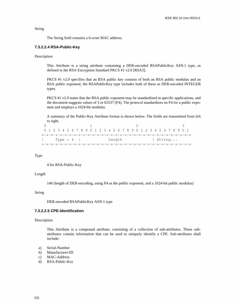
IEEE 802.16.1mc-00/21r1
String
The String field contains a 6-octet MAC address.
7.3.2.2.4 RSA-Public-Key
Description
This Attribute is a string attribute containing a DER-encoded RSAPublicKey ASN.1 type, asdefined in the RSA Encryption Standard PKCS #1 v2.0 [RSA3].
PKCS #1 v2.0 specifies that an RSA public key consists of both an RSA public modulus and anRSA public exponent; the RSAPublicKey type includes both of these as DER-encoded INTEGERtypes.
PKCS #1 v2.0 states that the RSA public exponent may be standardized in specific applications, andthe document suggests values of 3 or 65537 (F4). The protocol standardizes on F4 for a public expo-nent and employs a 1024-bit modulus.
A summary of the Public-Key Attribute format is shown below. The fields are transmitted from leftto right.
0 1 2 3 0 1 2 3 4 5 6 7 8 9 0 1 2 3 4 5 6 7 8 9 0 1 2 3 4 5 6 7 8 9 0 1 +-+-+-+-+-+-+-+-+-+-+-+-+-+-+-+-+-+-+-+-+-+-+-+-+-+-+-+-+-+-+-+-+ | Type = 4 | Length | String... +-+-+-+-+-+-+-+-+-+-+-+-+-+-+-+-+-+-+-+-+-+-+-+-+-+-+-+-+-+-+-+-+
Type
4 for RSA-Public-Key
Length
140 (length of DER-encoding, using F4 as the public exponent, and a 1024-bit public modulus)
String
DER-encoded RSAPublicKey ASN.1 type
7.3.2.2.5 CPE-Identification
Description
This Attribute is a compound attribute, consisting of a collection of sub-attributes. These sub-attributes contain information that can be used to uniquely identify a CPE. Sub-attributes shallinclude:
a) Serial-Numberb) Manufacturer-IDc) MAC-Addressd) RSA-Public-Key
231

IEEE 802.16.1mc-00/21r1
The CPE-Identification may also contain optional Vendor-Defined Attributes.
0 1 2 3 0 1 2 3 4 5 6 7 8 9 0 1 2 3 4 5 6 7 8 9 0 1 2 3 4 5 6 7 8 9 0 1 +-+-+-+-+-+-+-+-+-+-+-+-+-+-+-+-+-+-+-+-+-+-+-+-+-+-+-+-+-+-+-+-+ | Type = 5 | Length | Compound +-+-+-+-+-+-+-+-+-+-+-+-+-+-+-+-+-+-+-+-+-+-+-+-+-+-+-+-+-+-+-+-+
Type
5
Length
>= 126
7.3.2.2.6 Display-String
Description
This Attribute contains a textual message. It is typically used to explain a failure response, andmight be logged by the receiver for later retrieval by an SNMP manager. Display strings shall be nolonger than 128 bytes.
A summary of the Display-String Attribute format is shown below. The fields are transmitted fromleft to right.
0 1 2 3 0 1 2 3 4 5 6 7 8 9 0 1 2 3 4 5 6 7 8 9 0 1 2 3 4 5 6 7 8 9 0 1 +-+-+-+-+-+-+-+-+-+-+-+-+-+-+-+-+-+-+-+-+-+-+-+-+-+-+-+-+-+-+-+-+ | Type = 6 | Length | String... +-+-+-+-+-+-+-+-+-+-+-+-+-+-+-+-+-+-+-+-+-+-+-+-+-+-+-+-+-+-+-+-+
Type
6 for Display String
Length
>=0 and <= 128
String
A string of characters. There is no requirement that the character string be null terminated; the lengthfield always identifies the end of the string.
7.3.2.2.7 AUTH-Key
Description
The Authorization Key is an 20 byte quantity, from which a key encryption key, and two messageauthentication keys (one for upstream requests, and a second for downstream replies) are derived.
232

IEEE 802.16.1mc-00/21r1
This Attribute contains either a 96 or a 128-octet quantity containing the Authorization Key RSA-encrypted with the CPE’s 1024-bit RSA public key. Details of the RSA encryption procedure aregiven in section 7.5. The ciphertext produced by the RSA algorithm will be the length of the RSAmodulus, i.e., 128 octets.
233

IEEE 802.16.1mc-00/21r1
0 1 2 3 0 1 2 3 4 5 6 7 8 9 0 1 2 3 4 5 6 7 8 9 0 1 2 3 4 5 6 7 8 9 0 1 +-+-+-+-+-+-+-+-+-+-+-+-+-+-+-+-+-+-+-+-+-+-+-+-+-+-+-+-+-+-+-+-+ | Type = 7 | Length | String ... +-+-+-+-+-+-+-+-+-+-+-+-+-+-+-+-+-+-+-+-+-+-+-+-+-+-+-+-+-+-+-+-+
Type
7 for AUTH-Key
Length
96 or 128
String
96 or 128-octet quantity representing an RSA-encrypted Authorization Key.
7.3.2.2.8 TEK
Description
This Attribute contains an 8-octet quantity that is a TEK DES key, encrypted with a Key EncryptionKey derived from the Authorization Key. TEK keys are encrypted using the Encrypt-Decrypt-Encrypt (EDE) mode of two-key triple DES. See Section 7.6, Cryptographic Methods, for details.
0 1 2 3 0 1 2 3 4 5 6 7 8 9 0 1 2 3 4 5 6 7 8 9 0 1 2 3 4 5 6 7 8 9 0 1 +-+-+-+-+-+-+-+-+-+-+-+-+-+-+-+-+-+-+-+-+-+-+-+-+-+-+-+-+-+-+-+-+ | Type = 8 | Length | String ... +-+-+-+-+-+-+-+-+-+-+-+-+-+-+-+-+-+-+-+-+-+-+-+-+-+-+-+-+-+-+-+-+
Type
8 for TEK
Length
8
String
64-bit quantity representing a (two-key triple DES EDE mode) encrypted traffic encryption key.
7.3.2.2.9 Key-Lifetime
Description
This Attribute contains the lifetime, in seconds, of an Authorization Key or TEK. It is a 32-bitunsigned quantity representing the number of remaining seconds that the associated key will bevalid.
234

IEEE 802.16.1mc-00/21r1
0 1 2 3 0 1 2 3 4 5 6 7 8 9 0 1 2 3 4 5 6 7 8 9 0 1 2 3 4 5 6 7 8 9 0 1 +-+-+-+-+-+-+-+-+-+-+-+-+-+-+-+-+-+-+-+-+-+-+-+-+-+-+-+-+-+-+-+-+ | Type = 9 | Length | uint32 ... | +-+-+-+-+-+-+-+-+-+-+-+-+-+-+-+-+-+-+-+-+-+-+-+-+-+-+-+-+-+-+-+-+ | ... uint32 | +-+-+-+-+-+-+-+-+-+-+-+-+-+-+-+-+-+-+-+-+-+-+-+-+
Type
9 for Key-Lifetime
Length
4
uint32
32-bit quantity representing key lifetime
A key lifetime of zero indicates that the corresponding Authorization Key or traffic encryption keyis not valid.
7.3.2.2.10 Key-Sequence-Number
Description
This Attribute contains a 4-bit sequence number for a TEK or Authorization Key. The 4-bit quantity,however, is stored in a single octet, with the high-order 4 bits set to 0.
A summary of the Key-Sequence-Number Attribute format is shown below. The fields are transmit-ted from left to right.
0 1 2 3 0 1 2 3 4 5 6 7 8 9 0 1 2 3 4 5 6 7 8 9 0 1 2 3 4 5 6 7 8 9 0 1 +-+-+-+-+-+-+-+-+-+-+-+-+-+-+-+-+-+-+-+-+-+-+-+-+-+-+-+-+-+-+-+-+ | Type = 10 | Length | uint8 | +-+-+-+-+-+-+-+-+-+-+-+-+-+-+-+-+-+-+-+-+-+-+-+-+-+-+-+-+-+-+-+-+
Ty pe
10 for Key-Sequence-Number
Length
1
uint8
4-bit sequence number
235

IEEE 802.16.1mc-00/21r1
7.3.2.2.11 HMAC-Digest
Description
This Attribute contains a keyed hash used for message authentication. The HMAC algorithm isdefined in [RFC2104]. The HMAC algorithm is specified using a generic cryptographic hash algo-rithm. Privacy uses a particular version of HMAC that employs the Secure Hash Algorithm (SHA-1), defined in [FIPS-180-1][FIPS-180-1].
A summary of the HMAC-Digest Attribute format is shown below. The fields are transmitted fromleft to right.
0 1 2 3 0 1 2 3 4 5 6 7 8 9 0 1 2 3 4 5 6 7 8 9 0 1 2 3 4 5 6 7 8 9 0 1 +-+-+-+-+-+-+-+-+-+-+-+-+-+-+-+-+-+-+-+-+-+-+-+-+-+-+-+-+-+-+-+-+ | Type = 11 | Length | String ... +-+-+-+-+-+-+-+-+-+-+-+-+-+-+-+-+-+-+-+-+-+-+-+-+-+-+-+-+-+-+-+-+
Type
11 for HMAC-Digest
Length
20-octets
String
A 160-bit (20 octet) keyed SHA hash
7.3.2.2.12 SAID
Description
This Attribute contains a 16-bit SAID (SAID) used by the Privacy Protocol as the security associa-tion identifier.
236

IEEE 802.16.1mc-00/21r1
0 1 2 3 0 1 2 3 4 5 6 7 8 9 0 1 2 3 4 5 6 7 8 9 0 1 2 3 4 5 6 7 8 9 0 1 +-+-+-+-+-+-+-+-+-+-+-+-+-+-+-+-+-+-+-+-+-+-+-+-+-+-+-+-+-+-+-+-+ | Type = 12 | Length | uint16 ... | +-+-+-+-+-+-+-+-+-+-+-+-+-+-+-+-+-+-+-+-+-+-+-+-+-+-+-+-+-+-+-+-+ | ...uint16 | +-+-+-+-+-+-+-+-+
Type
12 for SAID
Length
2
uint16
16-bit quantity representing a SAID
7.3.2.2.13 TEK-Parameters
Description
This Attribute is a compound attribute, consisting of a collection of sub-attributes. These sub-attributes represent all security parameters relevant to a particular generation of a SAID’s TEK.
A summary of the TEK-Parameters Attribute format is shown below. The fields are transmitted fromleft to right.
0 1 2 3 0 1 2 3 4 5 6 7 8 9 0 1 2 3 4 5 6 7 8 9 0 1 2 3 4 5 6 7 8 9 0 1 +-+-+-+-+-+-+-+-+-+-+-+-+-+-+-+-+-+-+-+-+-+-+-+-+-+-+-+-+-+-+-+-+ | Type = 13 | Length | Compound... +-+-+-+-+-+-+-+-+-+-+-+-+-+-+-+-+-+-+-+-+-+-+-+-+-+-+-+-+-+-+-+-+
Type
13 for TEK-Parameters
Length
33
Compound
237

IEEE 802.16.1mc-00/21r1
The Compound field contains the following sub-Attributes:
7.3.2.2.14 CBC-IV
Description
This Attribute contains a 64-bit (8-octet) value specifying a Cipher Block Chaining (CBC) Initial-ization Vector.
A summary of the HMAC-Digest Attribute format is shown below. The fields are transmitted fromleft to right.
0 1 2 3 0 1 2 3 4 5 6 7 8 9 0 1 2 3 4 5 6 7 8 9 0 1 2 3 4 5 6 7 8 9 0 1 +-+-+-+-+-+-+-+-+-+-+-+-+-+-+-+-+-+-+-+-+-+-+-+-+-+-+-+-+-+-+-+-+ | Type = 15 | Length | String ... +-+-+-+-+-+-+-+-+-+-+-+-+-+-+-+-+-+-+-+-+-+-+-+-+-+-+-+-+-+-+-+-+
Type
15 for CBC-IV
Length
8 octets
String
A 64-bit quantity representing a DES-CBC initialization vector.
7.3.2.2.15 Error-Code
Description
This Attribute contains a one-octet error code providing further information about an AuthorizationReject, Key Reject, Authorization Invalid, or TEK Invalid.
A summary of the Error-Code Attribute format is shown below. The fields are transmitted from leftto right.
Table 48—TEK-Parameters Sub-Attributes
Attribute Contents
TEK TEK, encrypted (two-key triple DES-EDE mode) with the KEK
Key-Lifetime TEK Remaining Lifetime
Key-Sequence-Number TEK Sequence Number
CBC-IV Cipher Block Chaining (CBC) Initialization Vector
238

IEEE 802.16.1mc-00/21r1
0 1 2 3 0 1 2 3 4 5 6 7 8 9 0 1 2 3 4 5 6 7 8 9 0 1 2 3 4 5 6 7 8 9 0 1 +-+-+-+-+-+-+-+-+-+-+-+-+-+-+-+-+-+-+-+-+-+-+-+-+-+-+-+-+-+-+-+-+ | Type = 16 | Length | uint8 | +-+-+-+-+-+-+-+-+-+-+-+-+-+-+-+-+-+-+-+-+-+-+-+-+-+-+-+-+-+-+-+-+
Type
16 for Error-Code
Length
1
uint8
1-octet error code
A BS shall include the Error-Code Attribute in all Authorization Reject, Authorization Invalid, KeyReject and TEK Invalid messages. Table 49 lists code values for use with this Attribute. The BS mayemploy the nonzero error codes (1-8) listed below; it may, however, return a code value of zero (0).Error code values other than those defined in Table 49 shall be ignored. Returning a code value ofzero sends no additional failure information to the CPE; for security reasons, this may be desirable.
Error code 6, Permanent Authorization Failure, is used to indicate a number of different error condi-tions affecting the PKM authorization exchange. These include:
a) an unknown manufacturer; i.e., the BS does not have the CA certificate belonging to the issuer of aCPE certificate
Table 49—Error-Code Attribute Code Values
Error Code Messages Description
0 all no information
1 Auth Reject, Auth Invalid Unauthorized CPE
2 Auth Reject, Key Reject Unauthorized SAID
3 Auth Invalid Unsolicited
4 Auth Invalid, TEK Invalid Invalid Key Sequence Number
5 Auth Invalid Message (Key Request) authentication failure
6 Auth Reject Permanent Authorization Failure
7 Map Reject not authorized for requested downstream traffic flow
8 Map Reject downstream traffic flow not mapped to SAID
239

IEEE 802.16.1mc-00/21r1
pts aterma- that
viding may
cturer-ntified
versal iden-
from
b) CPE certificate has an invalid signaturec) ASN.1 parsing failure during verification of CPE certificated) CPE certificate is on the “hot list”e) inconsistencies between certificate data and data in accompanying PKM attributesf) CPE and BS have incompatible security capabilities
Their common property is that the failure condition is considered permanent: any re-attemauthorization would continue to result in Authorization Rejects. Details about the cause of a Pnent Authorization Failure may be reported to the CPE in an optional Display-String Attributemay accompany the Error-Code Attribute in Authorization Reject messages. Note that prothis additional detail to the CPE should be administratively controlled within the BS. The BSlog these Authorization failures, or even trap then to an SNMP manager.
7.3.2.2.16 Vendor-Defined
The Vendor-Defined Attribute is a compound attribute whose first sub-attribute shall be the ManufaID Attribute. Subsequent Attribute(s) are user defined, with Type values as-signed by the vendor ideby the previous Manufacturer-ID Attribute.
0 1 2 3 0 1 2 3 4 5 6 7 8 9 0 1 2 3 4 5 6 7 8 9 0 1 2 3 4 5 6 7 8 9 0 1 +-+-+-+-+-+-+-+-+-+-+-+-+-+-+-+-+-+-+-+-+-+-+-+-+-+-+-+-+-+-+-+-+ | Type = 127 | Length | Compound ... +-+-+-+-+-+-+-+-+-+-+-+-+-+-+-+-+-+-+-+-+-+-+-+-+-+-+-+-+-+-+-+-+
Type
1 27 for Vendor-Defined
Length
>= 6
Compound
The first sub-attribute shall be Manufacturer-ID. Subsequent attributes can include both uniTypes (i.e., defined within this specification) and vendor-defined Types, specific to the vendortified in the preceding Manufacturer-ID sub-attribute.
7.3.2.2.17 CA-Certificate
Description
This Attribute is a string attribute containing an X.509 CA Certificate, as defined in [X.509].
A summary of the CA-Certificate Attribute format is shown below. The fields are transmitted left to right.
0 1 2 3 0 1 2 3 4 5 6 7 8 9 0 1 2 3 4 5 6 7 8 9 0 1 2 3 4 5 6 7 8 9 0 1 +-+-+-+-+-+-+-+-+-+-+-+-+-+-+-+-+-+-+-+-+-+-+-+-+-+-+-+-+-+-+-+-+ | Type = 17 | Length | String...
240

IEEE 802.16.1mc-00/21r1
09].
from
ximum
ver-
+-+-+-+-+-+-+-+-+-+-+-+-+-+-+-+-+-+-+-+-+-+-+-+-+-+-+-+-+-+-+-+-+
Type
17 for CA-Certificate
Length
Variable. Length shall not cause resulting MAC management message to exceed the maximumallowed size.
String
X.509 CA Certificate (DER-encoded ASN.1)
7.3.2.2.18 CPE-Certificate
Description
This Attribute is a string attribute containing a CPE’s X.509 User Certificate, as defined in [X.5
A summary of the CPE-Certificate Attribute format is shown below. The fields are transmittedleft to right.
0 1 2 3 0 1 2 3 4 5 6 7 8 9 0 1 2 3 4 5 6 7 8 9 0 1 2 3 4 5 6 7 8 9 0 1 +-+-+-+-+-+-+-+-+-+-+-+-+-+-+-+-+-+-+-+-+-+-+-+-+-+-+-+-+-+-+-+-+ | Type = 18 | Length | String... +-+-+-+-+-+-+-+-+-+-+-+-+-+-+-+-+-+-+-+-+-+-+-+-+-+-+-+-+-+-+-+-+
Type
18 for CPE-Certificate
Length
Variable. Length shall not cause resulting MAC management message to exceed the maallowed size.
String
X.509 User Certificate (DER-encoded ASN.1)
7.3.2.2.19 Security-Capabilities
Description
The Security-Capabilities Attribute is a compound attribute whose sub-attributes identify thesion of Privacy a CPE supports and the cryptographic suite(s) a CPE supports.
0 1 2 3 0 1 2 3 4 5 6 7 8 9 0 1 2 3 4 5 6 7 8 9 0 1 2 3 4 5 6 7 8 9 0 1 +-+-+-+-+-+-+-+-+-+-+-+-+-+-+-+-+-+-+-+-+-+-+-+-+-+-+-+-+-+-+-+-+ | Type = 19 | Length | Compound ... +-+-+-+-+-+-+-+-+-+-+-+-+-+-+-+-+-+-+-+-+-+-+-+-+-+-+-+-+-+-+-+-+
241

IEEE 802.16.1mc-00/21r1
Type
19 for Security-Capabilities
Length
>=9
Compound
The Compound field contains the following sub-Attributes:
7.3.2.2.20 Cryptographic-Suite
Description
0 1 2 3 0 1 2 3 4 5 6 7 8 9 0 1 2 3 4 5 6 7 8 9 0 1 2 3 4 5 6 7 8 9 0 1 +-+-+-+-+-+-+-+-+-+-+-+-+-+-+-+-+-+-+-+-+-+-+-+-+-+-+-+-+-+-+-+-+ | Type = 20 | Length | uint16 ... | +-+-+-+-+-+-+-+-+-+-+-+-+-+-+-+-+-+-+-+-+-+-+-+-+-+-+-+-+-+-+-+-+ | ...uint16 | +-+-+-+-+-+-+-+-+
Type
20 for Cryptographic-Suite
Length
2
Uint16
A 16-bit integer identifying a pairing of a data encryption algorithm (encoded in the left-most, mostsignificant, byte) and a data authentication algorithm (encoded in the right-most, least significant,
Table 50—Security-Capabilities Sub-Attributes
Attribute Contents
Cryptographic-Suite-List list of supported cryptographic suites
Version version of Privacy supported
242

IEEE 802.16.1mc-00/21r1
byte). Currently, 56-bit and 40-bit DES are the only algorithms specified for use within security, andneither are paired with a data authentication algorithm.
7.3.2.2.21 Cryptographic-Suite-List
Description
0 1 2 3 0 1 2 3 4 5 6 7 8 9 0 1 2 3 4 5 6 7 8 9 0 1 2 3 4 5 6 7 8 9 0 1 +-+-+-+-+-+-+-+-+-+-+-+-+-+-+-+-+-+-+-+-+-+-+-+-+-+-+-+-+-+-+-+-+ | Type = 21 | Length | String... +-+-+-+-+-+-+-+-+-+-+-+-+-+-+-+-+-+-+-+-+-+-+-+-+-+-+-+-+-+-+-+-+
Type
Table 51—Data Encryption Algorithm Identifiers
Value Description
0 Reserved
1 CBC-Mode, 56-bit DES
2 CBC-Mode, 40-bit DES
3-255 Reserved
Table 52—Data Authentication Algorithm Identifiers
Value Description
0 No Data Authentication
1-255 Reserved
Table 53—Cryptographic-Suite Attribute Values
Value Description
256 (0x0100 hex) CBC-Mode 56-bit DES & no data authentication
512 (0x0200 hex) CBC-Mode 40-bit DES & no data authentication
all remaining values Reserved
243

IEEE 802.16.1mc-00/21r1
21 for Cryptographic-Suite-List
Length
2*n, where n=number of cryptographic suites listed
Uint8
A list of byte pairs identifying a collection of cryptographic suites. Each byte pair represents a sup-ported cryptographic suite, with an encoding identical to the value field of the Cryptographic-SuiteAttribute (Section 7.3.2.2.20). The BS shall not interpret the relative ordering of byte pairs in the listas a CPE’s preferences amongst the cryptographic suites it supports.
7.3.2.2.22 Version
Description
0 1 2 3 0 1 2 3 4 5 6 7 8 9 0 1 2 3 4 5 6 7 8 9 0 1 2 3 4 5 6 7 8 9 0 1 +-+-+-+-+-+-+-+-+-+-+-+-+-+-+-+-+-+-+-+-+-+-+-+-+-+-+-+-+-+-+-+-+ | Type = 22 | Length | uint8 | +-+-+-+-+-+-+-+-+-+-+-+-+-+-+-+-+-+-+-+-+-+-+-+-+-+-+-+-+-+-+-+-+
Type
22 for Version
Length
1
Uint8
A 1-octet code identifying a version of Privacy security.
7.3.2.2.23 SA-Descriptor
Description
Table 54—Version Attribute Values
Value Description
0 Reserved
1 Current Privacy
2-255 Reserved
244

IEEE 802.16.1mc-00/21r1
The SA-Descriptor Attribute is a compound attribute whose sub-attributes describe the properties ofa Security Association. These properties include the SAID, the SA type, and the cryptographic suiteemployed within the SA.
0 1 2 3 0 1 2 3 4 5 6 7 8 9 0 1 2 3 4 5 6 7 8 9 0 1 2 3 4 5 6 7 8 9 0 1 +-+-+-+-+-+-+-+-+-+-+-+-+-+-+-+-+-+-+-+-+-+-+-+-+-+-+-+-+-+-+-+-+ | Type = 23 | Length | Compound... +-+-+-+-+-+-+-+-+-+-+-+-+-+-+-+-+-+-+-+-+-+-+-+-+-+-+-+-+-+-+-+-+
Type
23 for SA-Descriptor
Length
14
Compound
The Compound field contains the following sub-Attributes:
7.3.2.2.24 SA-Type
Description
Identifies Type of SA. Privacy defines three SA types: Primary, Static, Dynamic. 0 1 2 3 0 1 2 3 4 5 6 7 8 9 0 1 2 3 4 5 6 7 8 9 0 1 2 3 4 5 6 7 8 9 0 1 +-+-+-+-+-+-+-+-+-+-+-+-+-+-+-+-+-+-+-+-+-+-+-+-+-+-+-+-+-+-+-+-+ | Type = 24 | Length | uint8 | +-+-+-+-+-+-+-+-+-+-+-+-+-+-+-+-+-+-+-+-+-+-+-+-+-+-+-+-+-+-+-+-+
Type
24 for SA-Type
Length
1
Table 55—SA-Descriptor Sub-Attributes
Attribute Contents
SAID Security Association ID
SA-Type Type of SA
Cryptographic-Suite pairing of data encryption and data authentication algorithms employed within the SA
245

IEEE 802.16.1mc-00/21r1
Uint8
A 1-octet code identifying the value of SA-type as defined in Table 56.
7.3.2.2.25 SA-Query
Description
Compound Attribute used in SA Map Request to specify mapping query arguments. Query argu-ments include the query type and any addressing attributes particular to that query type - theaddressing attributes identify a particular downstream traffic flow that a SA mapping is beingrequested for. Currently, the only query type specified is Multicast, and the addressing argumentassociated with that type is an IP group address.
0 1 2 3 0 1 2 3 4 5 6 7 8 9 0 1 2 3 4 5 6 7 8 9 0 1 2 3 4 5 6 7 8 9 0 1 +-+-+-+-+-+-+-+-+-+-+-+-+-+-+-+-+-+-+-+-+-+-+-+-+-+-+-+-+-+-+-+-+ | Type = 25 | Length | Compound... +-+-+-+-+-+-+-+-+-+-+-+-+-+-+-+-+-+-+-+-+-+-+-+-+-+-+-+-+-+-+-+-+
Type
25 for SA-Query
Length
11
Compound
The Compound field contains the following sub-Attributes:
Table 56—SA-Type Attribute Values
Value Description
0 Primary
1 Static
2 Dynamic
3-127 Reserved
128-255 Vendor-specific
246

IEEE 802.16.1mc-00/21r1
Table 7-3. SA-Query Sub-Attributes
7.3.3.2.26 SA-Query-Type
Description
This Attribute identifies an IP address used to identify an encrypted IP traffic flow. It is used, forexample, to specify an IP multicast group address.
A summary of the IP-Address Attribute format is shown below. The fields are transmitted from leftto right.
0 1 2 3 0 1 2 3 4 5 6 7 8 9 0 1 2 3 4 5 6 7 8 9 0 1 2 3 4 5 6 7 8 9 0 1 +-+-+-+-+-+-+-+-+-+-+-+-+-+-+-+-+-+-+-+-+-+-+-+-+-+-+-+-+-+-+-+-+ | Type = 26 | Length | uint8 | +-+-+-+-+-+-+-+-+-+-+-+-+-+-+-+-+-+-+-+-+-+-+-+-+-+-+-+-+-+-+-+-+
Type
26 for SA-Query-Type
Length
1
Uint8
A 1-octet code identifying the value of SA-Query-Type as defined in Table 57.
Attribute ContentsSA-Query-Type Type of QueryIP-Address required if SA-Query-Type = IP-Multicast; contains an IP group
address whose SA mapping is being requested.
Table 57—SA-Query-Type Attribute Values
Value Description
0 Reserved
1 IP Multicast
2-127 Reserved
128-255 Vendor-specific
247

IEEE 802.16.1mc-00/21r1
hanismami-
s firstf a new mes-
(TEK
that
ort up toation
a CPEctivatesset the
f the
imple-
7.4 Dynamic SA Mapping
7.4.1 Introduction
Dynamic Security Associations (Dynamic SAs), introduced in Section 7.1.1.3, are SAs that a BS establishesand eliminates, dynamically, in response to its enabling and disabling of specific downstream traffic flows.These traffic flows may be initiated by the actions of:
a) a CPE (Customer Premise Equipment) device attached to one of the BS’s client CPE, b) an application server within the head end, c) an OSS system, ord) other unspecified mechanisms.
Regardless of what triggers the establishment of a Dynamic SA within the BS, client CPE need a mecfor learning the mapping of a particular Privacy-protected downstream traffic flow to that flow’s dyncally assigned Security Association (and that SA’s corresponding SAID).
The details of this mechanism and the associated requirements are TBD.
7.5 Key Usage
7.5.1 BS
After a CPE completes MAC Registration, it initiates an Authorization exchange with its BS. The BS’receipt of an Authorization Request message from the unauthorized CPE initiates the activation oAuthorization Key (AK), which the BS sends back to the requesting CPE in an Authorization Replysage. This AK will remain active until it expires according to its predefined lifetime, Authorization Key Life-time, a BS system configuration parameter (see Appendix A.2).
The BS shall use keying material derived from the CPE’s Authorization Key for:
a) verifying the HMAC-Digest in Key Requests received from that CPEb) encrypting (EDE mode two-key triple DES) the TEK in the Key Replies it sends to that CPE
is a sub-attribute of a Key Reply’s TEK-Parameters Attribute)c) calculating the HMAC-Digests it writes into Key Replies, Key Rejects and TEK Invalids sent to
CPE
The BS must always be prepared to send a CPE an AK upon request. The BS shall be able to supptwo simultaneously active AKs for each client CPE. The BS has two active AKs during an AuthorizKey transition period; the two active keys have overlapping lifetimes.
An Authorization Key transition period begins when the BS receives an Authorization Request from and the BS has a single active AK for that CPE. In response to this Authorization Request, the BS aa second AK, which it sends back to the requesting CPE in an Authorization Reply. The BS shall active lifetime of this second AK to be the remaining lifetime of the first AK, plus the predefined Authoriza-tion Key Lifetime; thus, the second, “newer” key will remain active for one Authorization Key Lifetimebeyond the expiration of the first, “older” key. The key transition period will end with the expiration oolder key. This is depicted in the top half of Figure 6-1.
The Authorization Key lifetime a BS reports in a Authorization reply shall reflect, as accurately as an mentation permits, the remaining lifetimes of AK at the time the reply message is sent.
248

IEEE 802.16.1mc-00/21r1
g twoe twow AK,
utho-s
PE. Ifuence
is as an
whensitionhe BShe BS
n vec-lappinge olderlf wayhall no
ed forccord-
ation
ent them ther TEK either
BS is
s.
thehanismf the
n key
e num-ct, as
As long as the BS is in the midst of a CPE’s Authorization Key transition period, and thus is holdinactive Authorization Keys for that CPE, it will respond to Authorization Requests with the newer of thactive keys. Once the older key expires, an Authorization Request will trigger the activation of a neand the start of a new key transition period.
If a CPE fails to reauthorize before the expiration of its most current AK, the BS will hold no active Arization keys for the CPE and will consider the CPE unauthorized. A BS shall remove from its keying tableall TEKs associated with an unauthorized CPE’s Primary SA.
A BS shall use a CPE’s active AK(s) to verify the HMAC-digest in Key Requests received from the Ca BS receives a Key Request while in an AK transition period, and the accompanying AK Key SeqNumber indicates the Request was authenticated with the newer of the two AKs, the BS identifies thimplicit acknowledgment that the CPE has obtained the newer of the CPE’s two active AKs.
A BS shall use an active AK when calculating HMAC-Digests in Key Replies and Key Rejects, andencrypting the TEK in Key Replies. When sending Key Replies or Key Rejects within a key tranperiod (i.e., when two active AKs are available), if the newer key has been implicitly acknowledged, tshall use the newer of the two active AKs; if the newer key has not been implicitly acknowledged, tshall use the older of the two active AKs.
The upper half of Figure 6-1 illustrates the BS’s policy regarding its use of AKs.
The BS shall maintain two sets of active traffic encryption keys (and their associated CBC initializatiotors) per SAID. They correspond to two successive generations of keying material, and have overlifetimes. The newer TEK shall have a key sequence number one greater than (modulo 16) that of thTEK. Each TEK becomes active half way through the lifetime of its predecessor, and expires hathrough the lifetime of its successor. Once a TEK’s lifetime expires, the TEK becomes inactive and slonger be used.
The BS transitions between the two active TEKs differently depending on whether the TEK is usdownstream or upstream traffic. For each of its SAIDs, the BS shall transition between active TEKs aing to the following rules:
a) The BS shall use the older of the two active TEKs for encrypting downstream traffic. At expirof the older TEK, the BS will immediately transition to using the newer TEK for encryption.
b) For decryption of upstream traffic, a transition period is defined that begins once the BS has snewer TEK to a CPE within a Key Reply Message. The upstream transition period begins frotime the BS sends the newer TEK in a Key Reply Message and concludes once the oldeexpires. While in the transition period, the BS shall be able to decrypt upstream frames usingthe older or newer TEK.
Note that the BS encrypts with a given TEK for only the second half of that TEK’s total lifetime. The able, however, to decrypt with a TEK for the TEK’s entire lifetime.
The upper half of Figure 6-2 illustrates this BS’s management of a Privacy Security Association’s TEK
The BS is responsible for maintaining keying information for both primary and multicast SAIDs inabove manner. The Privacy Key Management protocol defined in this specification describes a mecfor synchronizing this keying information between a BS and its client CPE. It is the responsibility oCPE to update its keys in a timely fashion; the BS will transition to a new downstream encryptioregardless of whether a client CPE has retrieved a copy of that TEK.
The Key Replies sent by a BS contain TEK parameters (the TEK itself, a key lifetime, a key sequencber and a CBC IV) for the two active TEKs. The key lifetimes a BS reports in a Key Reply shall refle
249

IEEE 802.16.1mc-00/21r1
gth ofionng toization
cks the
igestste Key
ing AK
SAID. recent
eadyransi-
) algo-
l, in order
accurately as an implementation permits, the remaining lifetimes of these TEKs at the time the Key Replymessage is sent.
7.5.2 CPE
The CPE is responsible for sustaining authorization with its BS and maintaining an active AuthorizationKey. A CPE shall be prepared to use its two most recently obtained AKs.
AKs have a limited lifetime and must be periodically refreshed. A CPE refreshes its Authorization Key byre-issuing an Authorization Request to the BS. The Authorization state machine (Section 7.3.1.2) managesthe scheduling of Authorization Requests for refreshing AKs.
A CPE’s Authorization state machine schedules the beginning of reauthorization a configurable lentime (the Authorization Grace Time) before the CPE’s latest AK is scheduled to expire. The AuthorizatGrace Time is configured to provide a CPE with an authorization retry period that is sufficiently loallow for system delays and provide adequate time for the CPE to successfully complete an Authorexchange before the expiration of its most current AK.
Note that the BS does not require knowledge of the Authorization Grace Time. The BS, however, tralifetime of its Authorization Keys and shall deactive a key once it has expired.
A CPE shall use the newer of its two most recent Authorization Keys when calculating the HMAC-Dit attaches to Key Requests. It shall be able to use either of its two most recent AKs to authenticaReplies or Key Rejects, and to decrypt a Key Keply’s encrypted TEK. The CPE uses the accompanyKey Sequence Number to determine which of the two AKs to use.
The lower half of Figure 6-1 illustrates a CPE’s maintenance and usage of its Authorization Keys.
A CPE shall be capable of maintaining two successive sets of traffic keying material per authorizedThrough operation of its TEK state machines, a CPE attempts to always maintain a SAID’s two mostsets of traffic keying material.
For each of its authorized SAIDs, the CPE:
a) shall use the newer of its two TEKs to encrypt newly received upstream traffic. Traffic alrqueued up may use either TEK (in no specific order) for a brief period of time covering the ttion from the old to the new key.
b) shall be able to decrypt downstream traffic encrypted with either of the TEKs
7.6 Cryptographic Methods
This section specifies cryptographic algorithms and key sizes protocol uses.
7.6.1 Packet Data Encryption
Privacy shall use the Cipher Block Chaining (CBC) mode of the US Data Encryption Standard (DESrithm [FIPS-46, FIPS-46-1, FIPS-74, FIPS-81] to encrypt the MAC PDU payloads.
Privacy implementations shall support 56-bit DES.
CBC shall be initialized with an initialization vector that is provided, along with other SAID key materiaa BS’s Key Reply. Chaining is done block to block within a frame and reinitialized on a frame basis into make the system more robust to potential frame loss.
250

IEEE 802.16.1mc-00/21r1
vectorber of
block.
field is
ication
ee Sec-
or shallay also
50] pro-
, seven, right-d so that
Residual termination block processing shall be used to encrypt the final block of plaintext when the finalblock is less than 64 bits. Given a final block having n bits, where n is less than 64, the next-to-last cipher-text block is DES encrypted a second time, using the ECB mode, and the least significant n bits of the resultare exclusive ORed with the final n bits of the payload to generate the short final cipher block. In order forthe receiver to decrypt the short final cipher block, the receiver DES encrypts the next-to-last ciphertextblock, using the ECB mode, and exclusive ORs the left-most n bits with the short final cipher block in orderto recover the short final cleartext block. This encryption procedure is depicted in Figure 9.4 (pg. 195) of[SCHNEIER].
In the special case when the frame’s to-be-encrypted plaintext is less than 64 bits, the initializationshall be DES encrypted, and the left-most n bits of the resulting ciphertext corresponding to the numbits of the payload shall be exclusive ORed with the n bits of the payload to generate the short cipher1
7.6.2 Encryption of TEK
The BS encrypts the value fields of the TEK in the Key Reply messages it sends to client CPE. Thisencrypted using two-key triple DES in the encrypt-decrypt-encrypt (EDE) mode [SCHNEIER]:
encryption: C = Ek1[Dk2[Ek1[P]]]decryption: P = Dk1[Ek2[Dk1[C]]]P = Plaintext 64-bit TEKC = Ciphertext 64-bit TEKk1 = left-most 64 bits of the 128-bit KEKk2 = right-most 64 bits of the 128-bit KEKE[ ] = 56-bit DES ECB (electronic code book) mode encryptionD[ ] = 56-bit DES ECB decryption
Section 7.6.4 below describes how the KEK is derived from the Authorization key.
7.6.3 HMAC-Digest Algorithm
The keyed hash employed by the HMAC-Digest Attribute shall use the HMAC message authentmethod [RFC 2104] with the SHA-1 hash algorithm [FIPS-180-1].
Upstream and downstream message authentication keys are derived from the Authorization Key (stion 7.6.4 below for details).
7.6.4 Derivation of TEKs, KEKs and Message Authentication Keys
The BS generates Authorization Keys, TEKs and IVs. A random or pseudo-random number generatbe used to generate Authorization Keys and TEKs. A random or pseudo-random number generator mbe used to generate IVs; regardless of how they are generated, IVs shall be unpredictable. [RFC17vides recommended practices for generating random numbers for use within cryptographic systems.
[FIPS-81] defines DES keys as 8-octet (64-bit) quantities where the seven most significant bits (i.e.left-most bits) of each octet are the independent bits of a DES key, and the least significant bit (i.e.most bit) of each octet is a parity bit computed on the preceding seven independent bits and adjustethe octet has odd parity.
The keying material for two-key triple DES consists of two distinct (single) DES keys.
1This method of encrypting short payloads is vulnerable to attack: EXORing two sets of ciphertext encrypted in the above manner underthe same set of keying material will yield the EXOR of the corresponding sets of plaintext. Further investigation is required.
251

IEEE 802.16.1mc-00/21r1
CPE’s expo- speci- hashcified infor theoding
cer-
c expo- bits
nature
PKM does not require odd parity. The PKM protocol generates and distributes 8-octet DES keys of arbitraryparity, and it requires that implementations ignore the value of the least significant bit of each octet.
A key encryption key (KEK) and two message authentication keys are derived from a common Authoriza-tion Key. The following defines how these keys are derived:
KEK is the Key Encryption Key used to encrypt Traffic Encryption Keys.
HMAC_KEY_U is the message authentication key used in upstream Key Requests
HMAC_KEY_D is the message authentication key used in downstream Key Replies, Key Rejects and TEKInvalids.
SHA(x|y) denotes the result of applying the SHA function to the concatenated bit strings x and y.
Truncate(x,n) denotes the result of truncating x to its left-most n bits.
KEK = Truncate(SHA( K_PAD | AUTH_KEY ), 128)
HMAC_KEY_U = SHA( H_PAD_U | AUTH_KEY )
HMAC_KEY_D = SHA( H_PAD_D | AUTH_KEY )
Each _PAD_ is a 512 bit string:
K_PAD = 0x53 repeated 64 times.
H_PAD_U = 0x5C repeated 64 times.
H_PAD_D = 0x3A repeated 64 times.
7.6.5 Public-Key Encryption of Authorization Key
Authorization keys in Authorization Reply messages shall be RSA public-key encrypted, using the public key. The protocol uses F4 (65537 decimal, or equivalently, 010001 hexadecimal) as its publicnent and a modulus length of 1024 bits. The protocol employs the RSAES-OAEP encryption schemefied in version 2.0 of the PKCS#1 standard [RSA3]. RSAES-OAEP requires the selection of: afunction; a mask-generation function; and an encoding parameter string. The default selections spe[RSA3] shall be used when encrypting the authorization key. These default selections are: SHA-1 hash function; MGF1 with SHA-1 for the mask-generation function; and the empty string for the encparameter string.
7.6.6 Digital Signatures
The Protocol employs the RSA Signature Algorithm [RSA3] with SHA-1 [FIPS186] for all three of itstificate types.
As with its RSA encryption keys, Privacy uses F4 (65537 decimal, 010001 hexadecimal) as the publinent for its signing operation. The external authority Root CA will employ a modulus length of 2048(256 octets) for signing the Manufacturer CA certificates it issues. Manufacturer CAs shall employ sigkey modulus lengths of at least 1024 bits, and no greater than 2048 bits.
252

IEEE 802.16.1mc-00/21r1
e jus-re date,
own-both
e con-
If Pri-setting disable-inser-
ncapsu-e Pri-
es from
7.6.7 Supporting Alternative Algorithms
The current specification requires the use of 56-bit DES for encrypting packet data, two-key triple DES forencrypting traffic encryption keys, 1024-bit RSA for encrypting Authorization keys, and 1024-to-2048-bitRSA for signing Privacy X.509 certificates. The choice of key lengths and algorithms, while appropriate forcurrent threat models and hardware capabilities, may be inappropriate in the future.
For example, it is generally agreed that DES is approaching the end of its practical usefulness as the industrystandard for symmetric encryption. NIST is currently overseeing the development and adoption of a newstandard encryption algorithm, commonly referred to as the Advanced Encryption Standard, or AES. Giventhe nature of the security services, the protocol is being asked to support (basic privacy at a level better thanor equal to that possible over dedicated wires, and conditional access to RF data transport services) as wellas the protocol’s flexible key management policy (i.e., setting of key lifetimes), service providers will btified in the continued reliance on DES for, at least, the next five years. Nevertheless, at some futuCPEs will need to adopt a stronger traffic encryption algorithm, possibly AES.
7.7 TFTP Configuration File Extensions
All of a CPE’s Privacy configuration parameter values are specified in the configuration file TFTP-dloaded by the CPE during RF MAC initialization. Privacy configuration setting fields are included in the CPE MIC and BS MIC calculations, and in a CPE’s registration requests.
7.7.1 Privacy Configuration Setting Encodings
The following type/length/value encodings for Privacy configuration settings shall be used in both thfiguration file and in MAC CPE registration requests.
The Privacy Enable configuration setting controls whether Privacy is enabled or disabled in a CPE.vacy is enabled, the Privacy Configuration Setting shall also be present. The Privacy Configuration may be present if Privacy is disabled. The separate Privacy Enable parameter allows an operator toor re-enable Privacy by toggling a single configuration parameter, thus not requiring the removal or retion of the larger set of Privacy Configuration parameters.
This field defines the parameters associated with Privacy operation. It is composed of a number of elated type/length/value fields. The type fields defined are only valid within the encapsulated Baselinvacy configuration setting string.
type length value
P_CFG n
7.7.1.1 Internal Baseline Privacy Encodings
7.7.1.1.1 Authorize Wait Timeout
The value of the field specifies retransmission interval, in seconds, of Authorization Request messagthe Authorize Wait state.
sub-type length value
1 4
Valid Range: 1 - 30
253

IEEE 802.16.1mc-00/21r1
Reauthorize Wait Timeout
The value of the field specifies retransmission interval, in seconds, of Authorization Request messages fromthe Authorize Wait state.
sub-type length value
2 4
Valid Range: 1 - 30
7.7.1.1.2 Authorization Grace Time
The value of this field specifies the grace period for re-authorization, in seconds.
sub-type length value
3 4
Valid Range: 1 - 6,047,999
7.7.1.1.3 Operational Wait Timeout
The value of this field specifies the retransmission interval, in seconds, of Key Requests from the Opera-tional Wait state.
sub-type length value
4 4
Valid Range: 1 - 10
7.7.1.1.4 Rekey Wait Timeout
The value of this field specifies the retransmission interval, in seconds, of Key Requests from the RekeyWait state.
sub-type length value
5 4
Valid Range: 1 - 10
7.7.1.1.5 TEK Grace Time
The value of this field specifies grace period, in seconds, for rekeying the TEK.
sub-type length value
6 4
Valid Range: 1 - 302399
254

IEEE 802.16.1mc-00/21r1
meters.ning Pri-
7.7.1.1.6 Authorize Reject Wait Timeout
The value of this field specifies how long a CPE waits (seconds) in the Authorize Reject Wait state afterreceiving an Authorization Reject.
sub-type length value
7 4
Valid Range: 1 - 600
7.7.1.1.7 SA Map Wait Timeout
The value of this field specifies the retransmission interval, in seconds, of SA Map Requests from the MapWait state.
sub-type length value
8 4
Valid Range: 1 - 10
7.7.1.1.8 SA Map Max Retries
The value of this field specifies the maximum number of Map Request retries allowed.
sub-type length value
9 4
Valid Range: 0 - 10
7.7.1.2 Parameter Guidelines
Below are recommended ranges and values for Privacy’s various configuration and operational paraThese ranges and default values may change as service providers gain operational experience runvacy.
255

IEEE 802.16.1mc-00/21r1
recom-ol withvalues
ly thanned toorrectlylikely to
Table 58—Recommended Operational Ranges for Privacy Configuration Parameters
The valid range (vs. recommended operational range) for Authorization and TEK lifetimes are:
a) Authorization Lifetime Valid Range: 1 - 6,048,000 secondsb) TEK Lifetime Valid Range: 1 - 604,800 seconds
Note that valid ranges defined for each of Privacy’s configuration parameters extend below the mended operational ranges. For the purposes of protocol testing, it is useful to run the privacy protoctimer values well below the low end of the recommended operational ranges. The shorter timer "speed up" prviacy’s clock, causing privacy protocol state machine events to occur far more rapidthey would under an "operational" configuration. While privacy implementations need not be desigoperate efficiently at this accelerated privacy pace, the protocol implementation should operate cunder these shorter timer values. Table 59 provides a list of shortened parameter values which are be employed in protocol conformance and certification testing.
System Name Description Minimum Value
Default Value
Maximum Value
BS Authorization Lifetime
Lifetime, in seconds, BS assigns to new Authorization Key
1 day (86,400 sec.)
7 days (604,800 sec.)
70 days (6,048000 sec.)
BS TEK Lifetime Lifetime, in seconds, BS assigns to new TEK
30 min. (1800 sec.)
12 hours (43,200 sec.)
7 days (604,800 sec.)
CPE Authorize Wait Timeout
Auth Req retransmission interval from Auth Wait state
2 sec. 10 sec. 30 sec.
CPE Reauthorize Wait Timeout
Auth Req retransmission interval from Reauth Wait state
2 sec. 10 sec. 30 sec.
CPE Authorization Grace Time
Time prior to Authorization expi-ration CPE begins re-authorization
5 min. (300 sec.)
10 min. (600 sec.)
35 days (3,024,000 sec).
CPE Operational Wait Timeout
Key Req retransmission interval from Op Wait state
1 sec. 1 sec. 10 sec.
CPE Rekey Wait Time-out
Key Req retransmission interval from Rekey Wait state
1 sec. 1 sec. 10 sec.
CPE TEK Grace Time Time prior to TEK expiration CPE begins rekeying
5 min. (300 sec)
1 hour (3,600 sec.)
3.5 days (302,399 sec)
CPE Authorize Reject Wait
Delay before re-sending Auth Request after receiving Auth Reject
10 sec. 60 sec. 10 min. (600 sec.)
CPE SA Map Wait Timeout
Map Request retransmission inter-val from Map Wait state
1 sec. 1 sec. 10 sec.
CPE SA Map Max Retries
Maximum number of times CPE retries SA Map Request before giving up
0 4 10
256

IEEE 802.16.1mc-00/21r1
Table 59—Shortened Privacy Parameter Values for Protocol Testing
The TEK Grace Time shall be less than half the TEK lifetime.
Authorization Lifetime 5 min. (300 sec.)
TEK Lifetime 3 min. (180 sec.)
Authorization Grace Time
1 min. (60 sec.)
TEK Grace time 1 min. (60 sec.)
257