Mechatronics Design Approach for Working Model of Swinging Boat in Amusement Park
5
International Journal of Automation and Power Engineering (IJAPE) Volume 2 Issue 4, May 2013 www.ijape.org 257 Mechatronics Design Approach for Working Model of Swinging Boat in Amusement Park Arko Djajadi, Nathaniel Tirta Adiatma, Prianggada I Tanaya Mechatronics Department, Faculty of Engineering Swiss German University (SGU) BSDCity, INDONESIA [email protected] Abstract The paper is concerned with mechatronics approach to design and construct a working model of a “Kora‐kora” Swinging Boat Ride for educational and entertainment applications based on the study of the actual ride in an amusement park. By constructing a working model of this ride, it is possible to learn and apply mechanical, electrical and programming aspects to solve similar problems creatively. From the mechanical aspect, it clearly represents pendulum movement. From electromechanical and programming systems, the left and right swing movement of the ride is driven by a DC motor under the control of a microcontroller. The sensor used to detect the swing of the boat is an optical encoder. From the passenger point of view, riding a swinging boat gives excitement and unique sensation due to the variation of gravitational acceleration. This gravitational acceleration is observed by using accelerometer to detect and measure the angular acceleration of the boat. Finally, the whole system is integrated and tested to evaluate its performance which proved to be very similar to the actual system. Keywords Swinging Boat; Mechatronic Approach; Working Model; Accelerometer, Embedded Controller Introduction DUFAN (Dunia Fantasi) is a famous theme park in North Jakarta. It has many rides and attractions, and one of the most famous rides is “Kora‐kora”. Most of the amusement parks in the world have this kind of ride. The original name of Kora‐kora is “Swinging ship”. The Swinging ship manufacturers produce many types of rides based on the passengers capacity. Those manufactures are Fabbri (www.fabbrigroup.com), Huss rides (www.hussrides.com). By studying the system of a swinging boat in Dunia Fantasi, the writer reveals that The Swinging ship is exactly a nicely designed mechatronics product which FIG. 1 THE ORIGINAL KORA‐KORA RIDE IN THE PARK FIG. 2 DRIVING WHEEL UNDER THE BOAT gives sensational feelings to its passengers. It is also serves as an educational tool to see many principles of physics, mechanics, electronics and control which work together in a controlled and synergetic way. This is a The driving wheel Ship’s keel Hub Steel Support Ship Spokes Control Room Boat
-
Upload
shirley-wang -
Category
Documents
-
view
213 -
download
0
description
http://www.ijape.org/ The paper is concerned with mechatronics approach to design and construct a working model of a “Kora-kora” Swinging Boat Ride for educational and entertainment applications based on the study of the actual ride in an amusement park. By constructing a working model of this ride, it is possible to learn and apply mechanical, electrical and programming aspects to solve similar problems creatively.
Transcript of Mechatronics Design Approach for Working Model of Swinging Boat in Amusement Park

International Journal of Automation and Power Engineering (IJAPE) Volume 2 Issue 4, May 2013 www.ijape.org
257
Mechatronics Design Approach for Working
Model of Swinging Boat in Amusement Park Arko Djajadi, Nathaniel Tirta Adiatma, Prianggada I Tanaya
Mechatronics Department, Faculty of Engineering
Swiss German University (SGU)
BSDCity, INDONESIA
Abstract
The paper is concerned with mechatronics approach to
design and construct a working model of a “Kora‐kora”
Swinging Boat Ride for educational and entertainment
applications based on the study of the actual ride in an
amusement park. By constructing a working model of this
ride, it is possible to learn and apply mechanical, electrical
and programming aspects to solve similar problems
creatively. From the mechanical aspect, it clearly represents
pendulum movement. From electromechanical and
programming systems, the left and right swing movement of
the ride is driven by a DC motor under the control of a
microcontroller. The sensor used to detect the swing of the
boat is an optical encoder. From the passenger point of view,
riding a swinging boat gives excitement and unique
sensation due to the variation of gravitational acceleration.
This gravitational acceleration is observed by using
accelerometer to detect and measure the angular acceleration
of the boat. Finally, the whole system is integrated and tested
to evaluate its performance which proved to be very similar
to the actual system.
Keywords
Swinging Boat; Mechatronic Approach; Working Model;
Accelerometer, Embedded Controller
Introduction
DUFAN (Dunia Fantasi) is a famous theme park in
North Jakarta. It has many rides and attractions, and
one of the most famous rides is “Kora‐kora”. Most of
the amusement parks in the world have this kind of
ride. The original name of Kora‐kora is “Swinging
ship”. The Swinging ship manufacturers produce many
types of rides based on the passengers capacity. Those
manufactures are Fabbri (www.fabbrigroup.com), Huss
rides (www.hussrides.com).
By studying the system of a swinging boat in Dunia
Fantasi, the writer reveals that The Swinging ship is
exactly a nicely designed mechatronics product which
FIG. 1 THE ORIGINAL KORA‐KORA RIDE IN THE PARK
FIG. 2 DRIVING WHEEL UNDER THE BOAT
gives sensational feelings to its passengers. It is also
serves as an educational tool to see many principles of
physics, mechanics, electronics and control which work
together in a controlled and synergetic way. This is a
The driving wheel
Ship’s keel
Hub
Steel Support
Ship Spokes
Control RoomBoat

www.ijape.org International Journal of Automation and Power Engineering (IJAPE) Volume 2 Issue 4, May 2013
258
good start to create a working model of the swinging
ride by employing mechatronics approach.
Mechatronics design practices have been reported in
many sources [1–6].
Fig. 1 is the picture of the actual system, while Fig. 2
shows the main driving wheel and mechanism at time
when the bottom of the boat touches it to create boat
movement back and forth.
Mechatronics Design Approach
System Design Overview and Work Breakdown
Stucture
FIG. 3 SYSTEM DESIGN OVERVIEW
FIG. 4 SYSTEM WORK BREAKDOWN STRUCTURE
The system design overview is illustrated as in Fig 3.
The swinging boat design is then represented in a
system work breakdown structure (SWBS) and given
in Fig. 4.
The operator of will communicate with the system
through the control panel user interface. The
microcontroller and the circuit inside the control panel
will give signal to rotate the motor so the miniature
boat will swing back and forth.
Subsystem Work Breakdown Stuctures
Next step of the design in to create the WBS of each
subsystem. Fig. 5 shows the result of the more detailed
Mechanical subsystem WBS. It is distinguished
between static and moving parts of the structure. As
the control panel is a separate design, it is assumed as a
separate design.
FIG. 5 COMPLETE MECHANICAL WORK BREAKDOWN
STRUCTURE
Next is the electrical and programming control work
breakdown structure. Its WBS is shown in Fig. 6.
FIG. 6 COMPLETE ELECTRICAL WORK BREAKDOWN
STRUCTURE
International Journal of Automation and Power Engineering (IJAPE) Volume 2 Issue 4, May 2013 www.ijape.org
259
Detailed Design and Fabrication
After the system and subsystems WBS are derived
based on the requirement and observation, then each
part is designed, produced and assembled. In this
paper, the writer will only focused on the most
important part from the mechatronics point of view.
Those are the driving mechanism where the
mechanical, electrical, and programming control
subsystem must be adjusted and synchronized to
generate the required movement of the boat, both
acceleration and deceleration. The driving wheel
assembly is given in Fig. 7, showing the wheel, the
bottom of the boat, the spring mechanism and some
wiring to its motor and encoder.
At the driving wheel mechanism, the most important
thing is to keep the wheel pushing the arc. By this
pushing action, the driving wheel is able to transfer
kinetic energy from the motor to move the ship back
and forth. On fig. 7, the wheel kept pushing the arc by
means of mechanical spring under the motor holder.
The motor holder is bolted at a fixed door hinge, so the
motor holder can move in an upward and downward
direction. When the ship is at a full swing position, the
driving wheel will not be pushed downward by the arc
plate. Meanwhile, the driving wheel will be pushed
downward during a full stop.
FIG. 7 THE ACTUAL DRIVING MOTOR AND ITS DRIVING
WHEEL
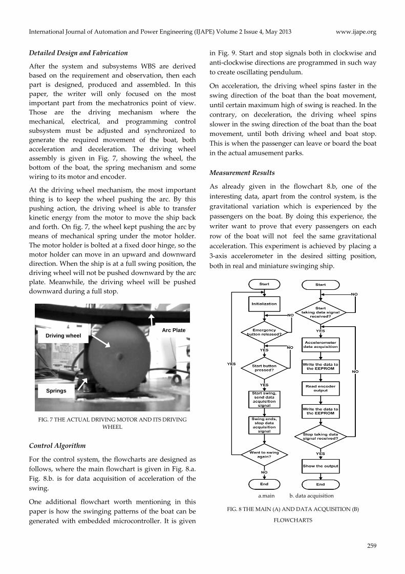
Control Algorithm
For the control system, the flowcharts are designed as
follows, where the main flowchart is given in Fig. 8.a.
Fig. 8.b. is for data acquisition of acceleration of the
swing.
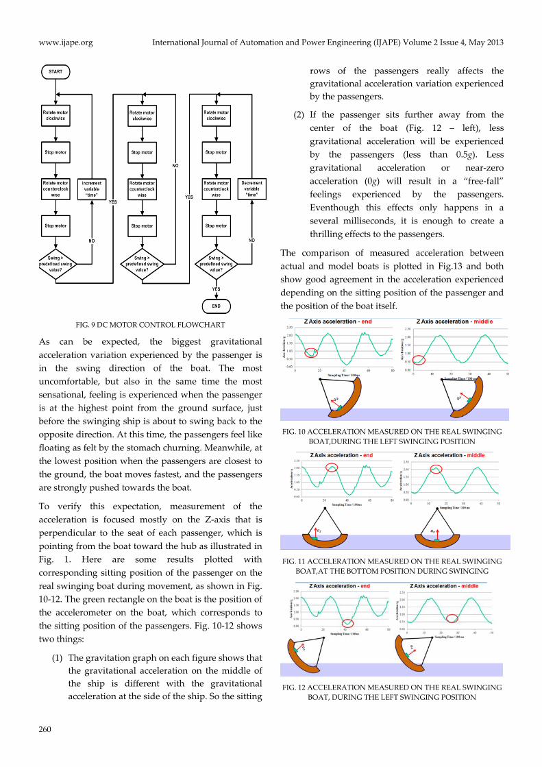
One additional flowchart worth mentioning in this
paper is how the swinging patterns of the boat can be
generated with embedded microcontroller. It is given
in Fig. 9. Start and stop signals both in clockwise and
anti‐clockwise directions are programmed in such way
to create oscillating pendulum.
On acceleration, the driving wheel spins faster in the
swing direction of the boat than the boat movement,
until certain maximum high of swing is reached. In the
contrary, on deceleration, the driving wheel spins
slower in the swing direction of the boat than the boat
movement, until both driving wheel and boat stop.
This is when the passenger can leave or board the boat
in the actual amusement parks.
Measurement Results
As already given in the flowchart 8.b, one of the
interesting data, apart from the control system, is the
gravitational variation which is experienced by the
passengers on the boat. By doing this experience, the
writer want to prove that every passengers on each
row of the boat will not feel the same gravitational
acceleration. This experiment is achieved by placing a
3‐axis accelerometer in the desired sitting position,
both in real and miniature swinging ship.
a.main b. data acquisition
FIG. 8 THE MAIN (A) AND DATA ACQUISITION (B)
FLOWCHARTS
Driving wheel
Springs
Arc Plate
www.ijape.org International Journal of Automation and Power Engineering (IJAPE) Volume 2 Issue 4, May 2013
260
FIG. 9 DC MOTOR CONTROL FLOWCHART
As can be expected, the biggest gravitational
acceleration variation experienced by the passenger is
in the swing direction of the boat. The most
uncomfortable, but also in the same time the most
sensational, feeling is experienced when the passenger
is at the highest point from the ground surface, just
before the swinging ship is about to swing back to the
opposite direction. At this time, the passengers feel like
floating as felt by the stomach churning. Meanwhile, at
the lowest position when the passengers are closest to
the ground, the boat moves fastest, and the passengers
are strongly pushed towards the boat.
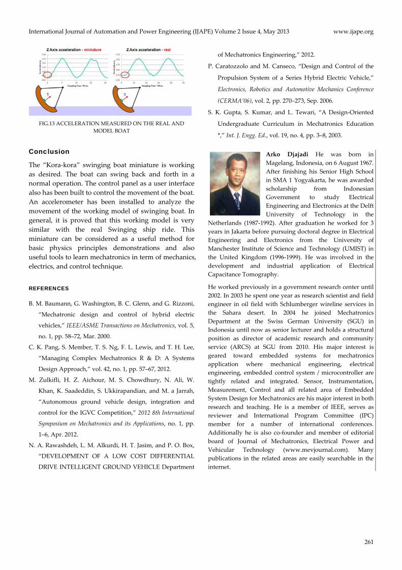
To verify this expectation, measurement of the
acceleration is focused mostly on the Z‐axis that is
perpendicular to the seat of each passenger, which is
pointing from the boat toward the hub as illustrated in
Fig. 1. Here are some results plotted with
corresponding sitting position of the passenger on the
real swinging boat during movement, as shown in Fig.
10‐12. The green rectangle on the boat is the position of
the accelerometer on the boat, which corresponds to
the sitting position of the passengers. Fig. 10‐12 shows
two things:
(1) The gravitation graph on each figure shows that
the gravitational acceleration on the middle of
the ship is different with the gravitational
acceleration at the side of the ship. So the sitting
rows of the passengers really affects the
gravitational acceleration variation experienced
by the passengers.
(2) If the passenger sits further away from the
center of the boat (Fig. 12 – left), less
gravitational acceleration will be experienced
by the passengers (less than 0.5g). Less
gravitational acceleration or near‐zero
acceleration (0g) will result in a “free‐fall”
feelings experienced by the passengers.
Eventhough this effects only happens in a
several milliseconds, it is enough to create a
thrilling effects to the passengers.
The comparison of measured acceleration between
actual and model boats is plotted in Fig.13 and both
show good agreement in the acceleration experienced
depending on the sitting position of the passenger and
the position of the boat itself.
FIG. 10 ACCELERATION MEASURED ON THE REAL SWINGING
BOAT,DURING THE LEFT SWINGING POSITION
FIG. 11 ACCELERATION MEASURED ON THE REAL SWINGING
BOAT,AT THE BOTTOM POSITION DURING SWINGING
FIG. 12 ACCELERATION MEASURED ON THE REAL SWINGING
BOAT, DURING THE LEFT SWINGING POSITION
International Journal of Automation and Power Engineering (IJAPE) Volume 2 Issue 4, May 2013 www.ijape.org
261
FIG.13 ACCELERATION MEASURED ON THE REAL AND
MODEL BOAT
Conclusion
The “Kora‐kora” swinging boat miniature is working
as desired. The boat can swing back and forth in a
normal operation. The control panel as a user interface
also has been built to control the movement of the boat.
An accelerometer has been installed to analyze the
movement of the working model of swinging boat. In
general, it is proved that this working model is very
similar with the real Swinging ship ride. This
miniature can be considered as a useful method for
basic physics principles demonstrations and also
useful tools to learn mechatronics in term of mechanics,
electrics, and control technique.
REFERENCES
B. M. Baumann, G. Washington, B. C. Glenn, and G. Rizzoni,
“Mechatronic design and control of hybrid electric
vehicles,” IEEE/ASME Transactions on Mechatronics, vol. 5,
no. 1, pp. 58–72, Mar. 2000.
C. K. Pang, S. Member, T. S. Ng, F. L. Lewis, and T. H. Lee,
“Managing Complex Mechatronics R & D: A Systems
Design Approach,” vol. 42, no. 1, pp. 57–67, 2012.
M. Zulkifli, H. Z. Aichour, M. S. Chowdhury, N. Ali, W.
Khan, K. Saadeddin, S. Ukkirapandian, and M. a Jarrah,
“Autonomous ground vehicle design, integration and
control for the IGVC Competition,” 2012 8th International
Symposium on Mechatronics and its Applications, no. 1, pp.
1–6, Apr. 2012.
N. A. Rawashdeh, L. M. Alkurdi, H. T. Jasim, and P. O. Box,
“DEVELOPMENT OF A LOW COST DIFFERENTIAL
DRIVE INTELLIGENT GROUND VEHICLE Department
of Mechatronics Engineering,” 2012.
P. Caratozzolo and M. Canseco, “Design and Control of the
Propulsion System of a Series Hybrid Electric Vehicle,”
Electronics, Robotics and Automotive Mechanics Conference
(CERMA’06), vol. 2, pp. 270–273, Sep. 2006.
S. K. Gupta, S. Kumar, and L. Tewari, “A Design‐Oriented
Undergraduate Curriculum in Mechatronics Education
*,” Int. J. Engg. Ed., vol. 19, no. 4, pp. 3–8, 2003.
Arko Djajadi He was born in
Magelang, Indonesia, on 6 August 1967.
After finishing his Senior High School
in SMA 1 Yogyakarta, he was awarded
scholarship from Indonesian
Government to study Electrical
Engineering and Electronics at the Delft
University of Technology in the
Netherlands (1987‐1992). After graduation he worked for 3
years in Jakarta before pursuing doctoral degree in Electrical
Engineering and Electronics from the University of
Manchester Institute of Science and Technology (UMIST) in
the United Kingdom (1996‐1999). He was involved in the
development and industrial application of Electrical
Capacitance Tomography.
He worked previously in a government research center until
2002. In 2003 he spent one year as research scientist and field
engineer in oil field with Schlumberger wireline services in
the Sahara desert. In 2004 he joined Mechatronics
Department at the Swiss German University (SGU) in
Indonesia until now as senior lecturer and holds a structural
position as director of academic research and community
service (ARCS) at SGU from 2010. His major interest is
geared toward embedded systems for mechatronics
application where mechanical engineering, electrical
engineering, embedded control system / microcontroller are
tightly related and integrated. Sensor, Instrumentation,
Measurement, Control and all related area of Embedded
System Design for Mechatronics are his major interest in both
research and teaching. He is a member of IEEE, serves as
reviewer and International Program Committee (IPC)
member for a number of international conferences.
Additionally he is also co‐founder and member of editorial
board of Journal of Mechatronics, Electrical Power and
Vehicular Technology (www.mevjournal.com). Many
publications in the related areas are easily searchable in the
internet.