
MECHATRONIC DESIGN AND DEVELOPMENT OF A...
20
MECHATRONIC DESIGN AND DEVELOPMENT OF A ROBOTIC ARM ZULKIFLI BIN MOHAMED UNIVERSITI TEKNOLOGI MALAYSIA
Transcript of MECHATRONIC DESIGN AND DEVELOPMENT OF A...

MECHATRONIC DESIGN AND DEVELOPMENT OF A ROBOTIC ARM
ZULKIFLI BIN MOHAMED
UNIVERSITI TEKNOLOGI MALAYSIA

iii
To my beloved mak, abah and family, for your love and continuous support.

iv
ACKNOWLEDGEMENT
First and foremost, I would like to thank my supervisor Prof. Madya Dr.
Musa bin Mailah for his guidance, critics and advice in completing this project.
Without his supervision it would be impossible to accomplish this project.
I would also like to thank Mr. Yeong Che Fai from FKE, Mr. Phang Che Yi
from Cytron and En. Mohamed Akmal Baharin from System and Control Laboratory,
which have guided me on the design and mechatronic part of the project. Also to the
members of Faculty of Mechanical Engineering, Universiti Teknologi Malaysia and
others who have provided assistance towards completing this work.
Then, I would like to thank my parents for their never ending support and
love. Without their continuous support and ‘doa’, I will not be here today. I am also
indebted to my family members and friends, especially Zaki, Yusri, Nizam and
Azmi, for their advice and support.
Finally, this appreciation is for Universiti Teknologi MARA for sponsoring
my study from the beginning to the end.

v
ABSTRACT
In this study a small scale robot arm was developed based on the actual rig.
The parameter from the model is used in the simulation process. Simulation
algorithm was developed and implemented within the Simulink environment. The
analysis is done by the implementation of different type of control scheme and
disturbances to the robot arm. The results from the simulation are used and compared
with experimental results. It is proven that a robot arm having a PD-AFC scheme is
very robust and stable compare to PD control.
vi
ABSTRAK
Dalam kajian ini, sebuah lengan robot berskala kecil telah dibina berdasarkan
lengan robot yang asal. Data – data dan ukuran dari model robot ini digunakan di
dalam proses simulasi. Algoritma simulasi dibangunkan dan simulasi dijalankan di
dalam Simulink. Analisis dijalankan dengan mengaplikasikan skema kawalan dan
gangguan yang berbeza kepada lengan robot. Hasil analisis dan kajian dari simulasi
dibandingkan dengan keputusan secara praktikal. Terbukti bahawa lengan robot yang
menggunakan skema PD-AFC adalah lebih stabil berbanding dengan kawalan PD
sahaja.
vii
TABLE OF CONTENTS
CHAPTER TITLE PAGE
1
TITLE
DECLARATION
DEDICATION
ACKNOWLEDGEMENT
ABSTRACT
ABSTRAK
TABLE OF CONTENTS
LIST OF TABLES
LIST OF FIGURES
LIST OF SYMBOLS
LIST OF ABBREVIATIONS
LIST OF APPENDICES
INTRODUCTION
1.1 Introduction
1.2 Research Objectives
1.3 Research Scopes
1.4 Research Methodology and Strategy
1.5 Expected Results
1.6 Organization of Thesis
i
ii
iii
iv
v
vi
vii
x
xi
xiv
xv
xvi
1
1
2
2
3
5
5

viii
2 THEORETICAL AND LITERATURE REVIEW
2.1 Introduction
2.2 Kinematics and Dynamics of Robot Arm
2.2.1 Basic Dynamic Equation
2.2.2 Newton-Euler Formulation
2.3 Robot Control
2.3.1 Position Control
2.3.2 Speed Control
2.3.3 Acceleration Control
2.4 Control Scheme
2.4.1 Classical Control
2.4.2 Active Force Control (AFC)
2.5 Disturbance Model
2.6 Related Software
2.7 Conclusion
6
6
6
8
9
14
15
16
17
17
18
19
20
21
22
3
4
SIMULATION
3.1 Introduction
3.2 Parameters of Robot Arm
3.3 Simulation
3.3.1 Prescribe Trajectory
3.3.2 Simulation Condition
3.4 Conclusion
DEVELOPMENT OF ROBOTIC ARM
4.1 Introduction
4.2 Main Components
4.2.1 Arm Design
4.2.2 Hobby Servo Motor
4.2.3 PIC Start-up Kit – SK40A
4.2.4 Microcontroller
23
23
23
26
28
29
30
31
31
31
31
33
35
37

ix
5
6
4.2.5 Potentiometer
4.2.6 Bootloader
4.3 Programming
4.3.1 Open Loop System
4.3.2 Closed Loop System (PD Control)
4.3.3 Signal Conversion
4.4 Summary of the Development Process
4.5 Conclusion
RESULTS AND DISCUSSION
5.1 Introduction
5.2 Simulation Results
5.2.1 No Disturbance
5.2.2 Constant Disturbance Torque at Joints
5.2.3 Spring Force at Link 2
5.2.4 Different Payload
5.3 Experimental Results
5.4 Conclusion
CONCLUSIONS
6.1 Conclusion
6.2 Recommendations
38
39
40
42
43
44
45
47
48
48
48
49
50
52
53
55
57
59
59
59
REFERENCES
Appendices A – D
61
65 - 88
x
LIST OF TABLES
TABLE NO. TITLE PAGE
3.1 Properties of the arm 25

xi
LIST OF FIGURES
FIGURE NO. TITLE PAGE
1.1
2.1
2.2
2.3
2.4
2.5
2.6
2.7
2.8
2.9
2.10
3.1
3.2
3.3
3.4
3.5
3.6
4.1
4.2
4.3
4.4
4.5
4.6
Project’s flowchart
Two-link robot arm
Isometric view of two-link robot arm
Free body diagram of link i
Simulink block diagram of robot dynamics
Position control of robot arm
Speed control of robot arm
Acceleration control of robot arm
An AFC block diagram
Simulink block diagram of PD-AFC scheme
Simulink block diagram of disturbance model
Robot Arm
Simulink block diagram of PD-AFC scheme
Simulink block diagram of robot dynamics
Simulink block diagram of disturbance model
Simulink block diagram of AFC loop
Prescribed trajectory
Robot arm design
Complete experimental setup
Hobby servo motor
Inside a servo motor
Duration of pulse
a) PIC start-up kit (SK40A) b) SK40A layout
4
7
8
9
14
15
16
17
19
20
21
24
26
27
27
28
29
32
32
33
34
35
36
xii
4.7
4.8
4.9
4.10
4.11
4.12
4.13
4.14
4.15
4.16
4.17
4.18
4.19
5.1
5.2
5.3
5.4
5.5
5.6
5.7
5.8
5.9
5.10
5.11
5.12
PIC 16F877A microcontroller
PIC 16F877A pin layout
10K Potentiometer
HyperTerminal for bootloader
a) Laptop programmer (Z000L) b) Desktop programmer
(L4128D)
Main routine flowchart
Interrupt service routine
Open loop system
Arm position
Closed loop system (PD control)
A/D block diagram of PIC 16F877A microcontroller
a) Original arm design b) Small scale arm
Potentiometer attachment
Position of joints, spring and payload
No Disturbance a) PD control b) PD-AFC control
Constant torque at both joints a) PD control b) PD-AFC
Constant torque at joints 1 a) PD control b) PD-AFC
Constant torque at joints 2 a) PD control b) PD-AFC
Spring force at link 2 (200 N/m) a) PD control b) PD-
AFC
Spring force at link 2 (400 N/m) a) PD control b) PD-
AFC
Payload position
Payload of 0.5 kg a) PD control b) PD-AFC
Payload of 2.5 kg a) PD control b) PD-AFC
Prescribed trajectory of arm (experimental)
Desired position of servo motor
37
38
38
39
39
40
41
42
42
43
44
45
46
49
50
51
51
52
52
53
54
54
55
56
57

xiii
LIST OF SYMBOLS
l - length of link
θ - joint angle of link
Τ - joint torque
ciivm &− - inertial force of link
ρacrylic - mass density per unit area for acrylic
m - mass of link
civ& - linear acceleration
g - gravitational acceleration
iiN ,1− - rotational motion of the arm
iiI ω - gyroscopic torque
f - force
Kp - proportional constant
Ki - integral constant
KD - derivatives constant
a - acceleration
mmot - mass of motor
h - thickness of link
v - volume of link
ktn - motor torque
I - moment of inertia
a - width of plate
b - length of plate
k - spring stiffness
Vcut - end point linear velocity,
D(t) - desired position

xiv
Y(t) - measured position
E(t) - error
C(t) - controller response
E(n) - current error
E(n-1) - previous error
T(s) - sampling period
xv
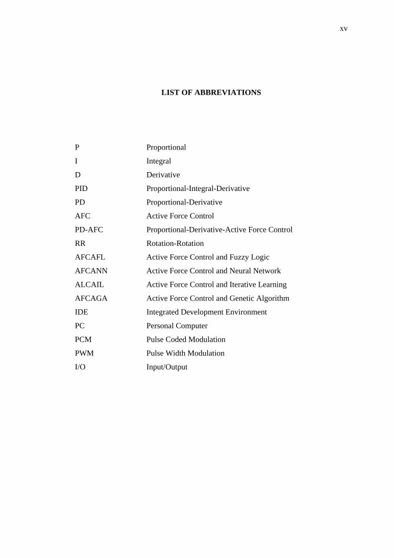
LIST OF ABBREVIATIONS
P Proportional
I Integral
D Derivative
PID Proportional-Integral-Derivative
PD Proportional-Derivative
AFC Active Force Control
PD-AFC Proportional-Derivative-Active Force Control
RR Rotation-Rotation
AFCAFL Active Force Control and Fuzzy Logic
AFCANN Active Force Control and Neural Network
ALCAIL Active Force Control and Iterative Learning
AFCAGA Active Force Control and Genetic Algorithm
IDE Integrated Development Environment
PC Personal Computer
PCM Pulse Coded Modulation
PWM Pulse Width Modulation
I/O Input/Output
xvi
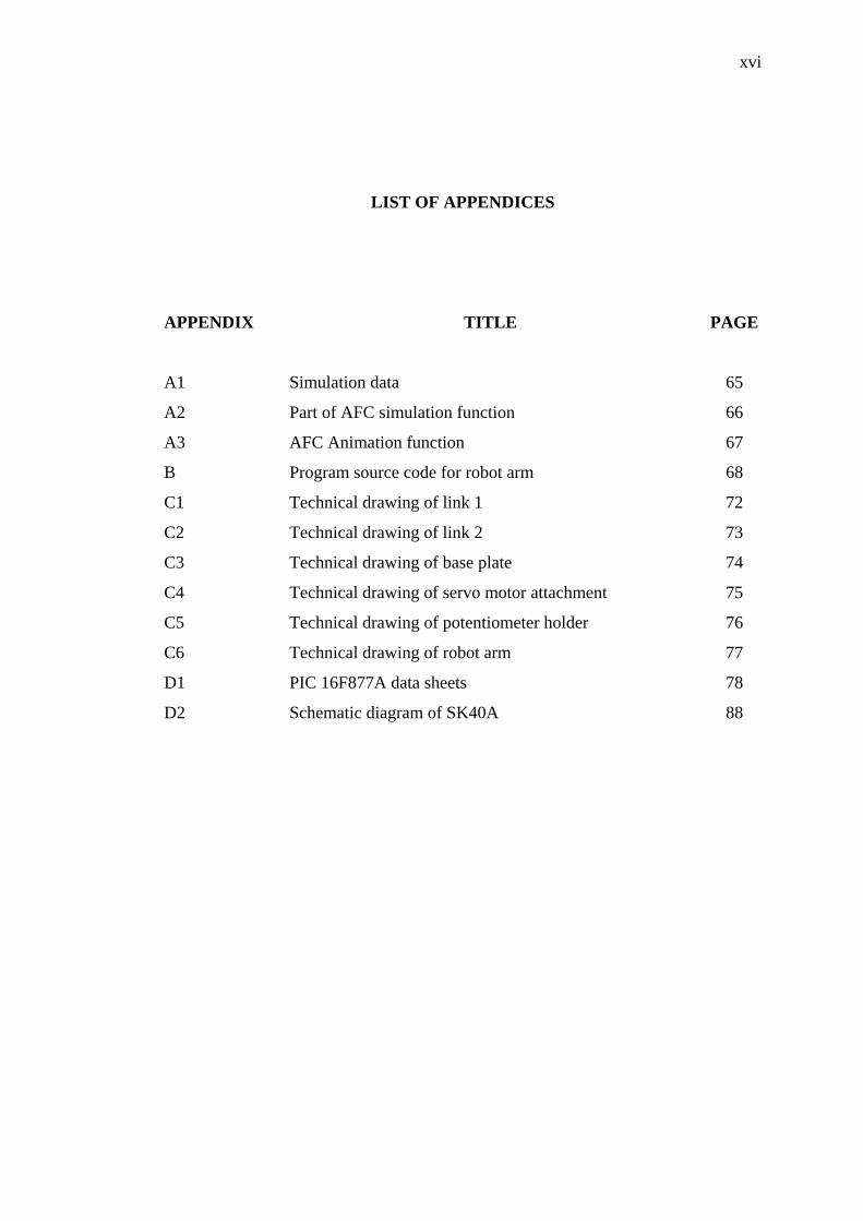
LIST OF APPENDICES
APPENDIX TITLE PAGE
A1
A2
A3
B
C1
C2
C3
C4
C5
C6
D1
D2
Simulation data
Part of AFC simulation function
AFC Animation function
Program source code for robot arm
Technical drawing of link 1
Technical drawing of link 2
Technical drawing of base plate
Technical drawing of servo motor attachment
Technical drawing of potentiometer holder
Technical drawing of robot arm
PIC 16F877A data sheets
Schematic diagram of SK40A
65
66
67
68
72
73
74
75
76
77
78
88
CHAPTER 1
INTRODUCTION
1.1 Introduction
This project is basically the continuation of previous research with some
modification and the use of different approaches. Previously, the focuses are on the
interfacing and control of a single link arm (Soong, 2001), experimental aspect of
interfacing and experimental aspects of single link arm (Goh, 2003) and the
implementation of Active Force Control (AFC) to a two-link robot arm (Pitowarno,
2002).
A robust and stable performance of a robot arm is very important as it deals
with working environment and disturbances. For example, in manufacturing, process
such as welding, cutting and spraying demands a highly robust and stable system.
Study on kinematics (Lee, 1983), static, dynamics (Lee, 1983), robot control scheme
(Astrom, 1995) and trajectory planning (Taylor, 1979) are very important, and there
are a lot more consideration needs to be considered in robot analysis. These factors
are important in order to have high quality product.
Many robot control methods had been introduced such as Proportional-
Integral-Derivative (PID) control, (Astrom, 1995), Adaptive Control, (Petros
Ioannou, 1991), Hybrid Control, Intelligent Control and AFC (Musa, 1998).
PID control is the most widely used control scheme. It is very robust and
stable for a relatively low speed and very little disturbance robot operation. The

2
combination of the controller depends on the needs of the system. It can be
Proportional alone or, the combination of Proportional with Integral (PI),
Proportional with Derivative (PD) or PID control.
Nowadays, most robot system will have these classical controls and it is
being upgraded with the implementation and combination with modern type of
control scheme such as, Active Force Control, Intelligent Control, Adaptive Control
and Hybrid Control. These control scheme will overcome the problem arise in PID
control and produce more stable and robust system. Therefore, the existence of
internal or external disturbance can be compensated.
1.2 Research Objectives
The objectives of the research are:
i. To model and simulate a robot arm with different control schemes and
operating conditions.
ii. To develop a physical robot arm and use a microcontroller as the
driver.
1.3 Research Scopes
The scopes of this project are:
• Simulation using two different control schemes and operating conditions.
• Development of small scale rig.
• Make use or PIC Microcontroller as the main component of the system.
• Development of an open loop system.
• Improving the system by upgrading it to a closed loop system.
3
• Development of the program both, for open and closed loop system.
• Test the rig.
1.4 Research Methodology and Strategy
The research methodology of the project can be described as follows:
• Literature review on robot areas, control scheme, microcontroller,
software and hardware.
• Study on existing rig, measure and obtain all the parameters needed in
order to design a small scale rig (length of link 1 and link 2, density, ρ of
acrylic, mass of motor 1 and 2 and mass of link 1 and link 2).
• Study on PIC Microcontroller (set up, advantages and the specification).
• Study on the software in order to do simulation and testing (MATLAB
6.5, Simulink 5.0, MPLAB IDE 7.0, PiCC Lite 8.02 and IC Prog).
• Study on control scheme and identify the problem and other related issues
(PD Control and AFC).
• Test the robustness and stability of the system by introducing different
type of disturbances (simulation).
• Make use of microcontroller which acts as the driver, controller and
analogue to digital converter.
• Perform experiment, compare, analyze and discuss the results.
This project was carried out within two semesters. The flowchart of the
project is shown in Figure 1.1:

4
Study on Existing Rig, Control Theory, Electronics, System Modeling, Microcontroller and Simulation
Literature Review (Books, Thesis, Journal & Papers)
Study on Software (MATLAB 6.5, Simulink 5.0, MPLAB IDE, PiCC
Lite and ICProg)
Design of Small Scale Robotic Arm (Design, Fabrication and Assembly)
Simulate New Parameters, Programming and Testing
Apply Control Strategy to Robot Arm
Perform Experiment, Test and Evaluation
Analysis and Discussion
Figure 1.1: Project’s flowchart
5
1.5 Expected Results
This project produces results that show the stability and robustness of the
proposed control scheme on a small scale two degree of freedom rigid robot arm.
1.6 Organization of Thesis
This report is basically divided into six main chapters. In Chapter 1, the
general idea of the project is stated. Introduction, project scope, methodology and
expected results are described in this chapter. Chapter 2 describes the fundamentals
of robot, dynamic analysis of robot arm, control scheme and other related topics.
Chapter 3 describes the simulation process with different operating conditions.
Chapter 4 gives the development of the robot arm and it includes design, fabrication
and programming. Chapter 5 presents the simulations and experimental results. The
final chapter (Chapter 6) describes the conclusions and recommendations of the
project.


