Mechanism and Machine Theory - ir.nctu.edu.tw · Some of indexing gears ... According to the...
14
Mathematical model and tooth surfaces of recess action worm gears with double-depth teeth Wei-Liang Chen a , Chung-Biau Tsay b, ⁎ a Department of Mechanical Engineering, National Chiao Tung University, Hsinchu 30010, Taiwan b Department of Mechanical and Computer-Aided Engineering, Feng Chia University, Taichung 40724, Taiwan article info abstract Article history: Received 28 September 2010 Received in revised form 9 July 2011 Accepted 21 July 2011 In this study, the surface equations of recess action (RA) worm gears with double-depth teeth, generated by a ZN worm-type hob cutter, are proposed. Based on the generation mechanism and the theory of gearing, a mathematical model of a series of worm gears, semi RA, full RA and standard proportional tooth types, with double-depth teeth is developed as the function of design parameters of the ZN worm-type hob cutter. According to the derived tooth surface equations, computer graphs of a series of worm gears with double-depth teeth are plotted. Tooth surface variations of the generated RA worm gears due to the varying pitch line, pressure angle and tooth height of the hob cutter are also investigated. © 2011 Elsevier Ltd. All rights reserved. Keywords: Recess action Double-depth teeth RA worm gear Tooth surface variation 1. Introduction Majority of gears are used to transfer power or torque. Few of gears, such as indexing gears, are applied to transmit precise control of angular motion, and transferring of power or torque becomes their secondary consideration. Some of indexing gears usually operate in the open air, or only use grease lubrication, especially that are used to drive military weapons, radio telescopes, satellite tracking antennas, etc. They need to run under the conditions of lower friction, more smooth and stable than equivalent gears. It is well-known that recess action gears (abbreviated to RA gears) have less wear with lower friction and less noise [1]. Buckingham [1] interpreted that friction of recess action is lower than that of approach action when gears are in meshing. Buckingham [2] also indicated that one of worm gear drives, the deep-tooth cylindrical worm drive, was manufactured by Delava- Holroyd Inc. and employed to precise rotation of the heavy 200-in. Mt. Palomar telescope. It has also been applied to a large range of finders. This worm gear drive is similar to that of the convectional type, but it is actually modified into a full RA worm gear drive with double-depth teeth and low pressure angle. Compared with the conventional type of worm gear drive, these modifications result in a large number of teeth in contact and high recess action inducing lower friction. Benefit of multiple tooth contact not only reduces kinematic errors but also averages the sum of all tooth errors. Crosher [3] interpreted that Zahnradfabrik OTT in Germany has developed worm gear sets having a small backlash, and OTT's specifications were also satisfied minimum total composite error in precise positioning. They were designed with a very high contact ratio (CR) in order to have a uniform and constant contact. This can be achieved with a low pressure angle, very long tooth flanks and a large number of worm gear teeth, etc. However, the limitation is the narrowness at the top of the teeth and the worm helix. Shigley and Mischke [4] defined CR of a gear pair as the average number of teeth in contact during the gear meshing. Therefore, the CR of an RA worm gear drive can be calculated by the rotational angle of a gear tooth, measured from the beginning contact point to the end contact point which can be calculated by applying the tooth contact analysis (TCA) results, divided by the angle formed by two successive teeth. Mechanism and Machine Theory 46 (2011) 1840–1853 ⁎ Corresponding author. E-mail address: [email protected] (C.-B. Tsay). 0094-114X/$ – see front matter © 2011 Elsevier Ltd. All rights reserved. doi:10.1016/j.mechmachtheory.2011.07.015 Contents lists available at ScienceDirect Mechanism and Machine Theory journal homepage: www.elsevier.com/locate/mechmt
Transcript of Mechanism and Machine Theory - ir.nctu.edu.tw · Some of indexing gears ... According to the...
Mathematical model and tooth surfaces of recess action worm gears withdouble-depth teeth
Wei-Liang Chen a, Chung-Biau Tsay b,⁎a Department of Mechanical Engineering, National Chiao Tung University, Hsinchu 30010, Taiwanb Department of Mechanical and Computer-Aided Engineering, Feng Chia University, Taichung 40724, Taiwan
a r t i c l e i n f o a b s t r a c t
Article history:Received 28 September 2010Received in revised form 9 July 2011Accepted 21 July 2011
In this study, the surface equations of recess action (RA) worm gears with double-depth teeth,generated by a ZN worm-type hob cutter, are proposed. Based on the generation mechanismand the theory of gearing, a mathematical model of a series of worm gears, semi RA, full RA andstandard proportional tooth types, with double-depth teeth is developed as the function ofdesign parameters of the ZN worm-type hob cutter. According to the derived tooth surfaceequations, computer graphs of a series of worm gears with double-depth teeth are plotted.Tooth surface variations of the generated RA worm gears due to the varying pitch line, pressureangle and tooth height of the hob cutter are also investigated.
© 2011 Elsevier Ltd. All rights reserved.
Keywords:Recess actionDouble-depth teethRA worm gearTooth surface variation
1. Introduction
Majority of gears are used to transfer power or torque. Few of gears, such as indexing gears, are applied to transmit precisecontrol of angular motion, and transferring of power or torque becomes their secondary consideration. Some of indexing gearsusually operate in the open air, or only use grease lubrication, especially that are used to drive military weapons, radio telescopes,satellite tracking antennas, etc. They need to run under the conditions of lower friction, more smooth and stable than equivalentgears. It is well-known that recess action gears (abbreviated to RA gears) have less wear with lower friction and less noise [1].
Buckingham [1] interpreted that friction of recess action is lower than that of approach action when gears are in meshing.Buckingham [2] also indicated that one of worm gear drives, the deep-tooth cylindrical worm drive, was manufactured by Delava-Holroyd Inc. and employed to precise rotation of the heavy 200-in. Mt. Palomar telescope. It has also been applied to a large rangeof finders. This worm gear drive is similar to that of the convectional type, but it is actually modified into a full RA worm gear drivewith double-depth teeth and low pressure angle. Compared with the conventional type of worm gear drive, these modificationsresult in a large number of teeth in contact and high recess action inducing lower friction. Benefit of multiple tooth contact not onlyreduces kinematic errors but also averages the sum of all tooth errors. Crosher [3] interpreted that Zahnradfabrik OTT in Germanyhas developedworm gear sets having a small backlash, and OTT's specifications were also satisfiedminimum total composite errorin precise positioning. Theywere designedwith a very high contact ratio (CR) in order to have a uniform and constant contact. Thiscan be achieved with a low pressure angle, very long tooth flanks and a large number of worm gear teeth, etc. However, thelimitation is the narrowness at the top of the teeth and the worm helix. Shigley and Mischke [4] defined CR of a gear pair as theaverage number of teeth in contact during the gear meshing. Therefore, the CR of an RA worm gear drive can be calculated by therotational angle of a gear tooth, measured from the beginning contact point to the end contact point which can be calculated byapplying the tooth contact analysis (TCA) results, divided by the angle formed by two successive teeth.
Mechanism and Machine Theory 46 (2011) 1840–1853
⁎ Corresponding author.E-mail address: [email protected] (C.-B. Tsay).
0094-114X/$ – see front matter © 2011 Elsevier Ltd. All rights reserved.doi:10.1016/j.mechmachtheory.2011.07.015
Contents lists available at ScienceDirect
Mechanism and Machine Theory
j ourna l homepage: www.e lsev ie r.com/ locate /mechmt
Buckingham [1] proposed how to design RAworm gears. Yang [5] proposed an interactive computer graphics program to applyto an optimum RA gear design. Siegal and Mabie [6] developed a method to maximize the ratio of recess action to approach actionby determining the individual hob offsets for a pair of spur gears designed to operate at nonstandard center distance. Meng andChen [7] investigated theoretically and experimentally the scuffing resistance of full RA gears, in comparison with semi RA andstandard ones. It appeared that full RA gearsmight prefer the pitting resistance and plastic-flow state to scuffing resistance in someextent than those of the others. Wildhaber [8] used the surface curvatures to obtain an approximate tooth contact for some wormgears generated by oversize hob cutters. Winter and Wilkesmann [9], and Bosch [10] proposed different methods to obtain moreprecise worm gear drive surfaces. Fang and Tsay [11] developed the mathematical model of conventional worm gear drives.
Up to now, only few researches have been investigated on the RA worm gears. However, mathematical model, computersimulation, tooth contact analysis and stress analysis of RA worm gears have not been studied yet. The aim of this paper is todevelop the mathematical model of the RA worm gears with double-depth teeth. According to the generation mechanism of RAworm gear drives and the theory of gearing [12], the mathematical model of the RA worm gears can be derived. Three types ofworm gear teeth, semi RA, full RA and standard proportional tooth, are concerned in this study. Based on the developedmathematical model, the computer graphs of semi RA, full RA and the standard proportional tooth worm gears can be plotted.Tooth surface variations of the RAworm gear teeth, due to the varying pitch line, pressure angle and tooth height of the hob cutter,are also investigated. The results of this study can be applied to further investigations on tooth contact analysis, kinematic errors,contact paths and contact patterns of the semi RA, full RA and standard proportional tooth worm gear drives.
2. Approach action and recess action of meshings for the semi RA, full RA and standard proportional tooth worm geardrives
Fig. 1 shows three types of worm gear drive meshing, semi RA, full RA and standard proportional tooth worm gear drives, withdouble-depth teeth at the same standard center distance. Fig. 1(a) shows the worm gear drive with standard proportional tooth
Nomenclatures
bx,bn width of hob cutter at varying pitch line, respectively (Fig. 3)C1 center distance of hob cutter and RA worm gear (Fig. 5)dx distance measured from the middle of hob cutter tooth height to the varying pitch line (Figs. 2 and 3(b))h straight-lined edge height of hob cutter cutting blade (Fig. 3(b))ht whole cutting blade height of hob cutter (Fig. 3(b))Lij coordinate transformation matrix transforming from coordinate system Sj to Si (Eqs. (26), (27), (29), and (31))l1 surface parameter of hob cutter (Fig. 3(b))Mij homogeneous coordinate transformation matrix transforming from coordinate system Sj to Si (Eqs. (8), (9), (18),
and (19))mn normal modulus (Fig. 2)mx axial modulus (Figs. 2 and 7), and mx=mn/cos λ1
m21 angular velocity ratio of hob cutter to RA worm gear (Eqs. (28), (33) and (34))N1,N1
(c) normal vectors of hob cutter tooth surface (Eqs. (12) and (15))Nx1, Ny1, Nz1 components of the normal vector expressed in coordinate system S1 (Eqs. (34))p1 lead-per-radian revolution of hob cutter blade surface (Fig. 4)R1, R2 position vectors of hob cutter and RA worm gear, respectivelyro, r1, rf outside radius, pitch radius and root radius of hob cutter, respectively (Fig. 3(c))r2 pitch radius of RA worm gearrc circular tip radius of hob cutter (Fig. 3(b))rt design parameter of hob cutter (Fig. 3)Si, Sj reference and rotational coordinate systems (i= f, g, p and j=c, 1, 2, 3 )T1, T2 number of teeth of hob cutter and RA worm gear, respectivelytc, tt transverse chordal thicknesses at pitch circle and throat circle of RA worm gear, respectively (Fig. 11)V12(1) relative velocity vector of hob cutter and RA worm gear expressed in coordinate system S1 (Eqs. (22) and (33))
Vi(1) velocity vectors of hob cutter and RA worm gear (i =1, 2) expressed in coordinate system S1 (Eqs. (22))
α1 pressure angle of hob cutter (Fig. 3(b))γ1 cross angle of hob cutter in generating RA worm gear (Fig. 5)θ1 rotation angle of hob cutter in screw surface generation (Fig. 4)λ1 lead angle of hob cutter (Fig. 4)ϕ1, ϕ2 rotational angles of hob cutter and RA worm gear, respectively (Fig. 5)ω1, ω2 angular velocities of hob cutter and RA worm gear, respectively (Eqs. (24), (25), (28) and (33))ωi
(j) angular velocity vectors, expressed in coordinate system Sj (j=1, p) of hob cutter and RA worm gear (i=1, g)(Eqs. (23)–(26) and (28))
1841W.-L. Chen, C.-B. Tsay / Mechanism and Machine Theory 46 (2011) 1840–1853
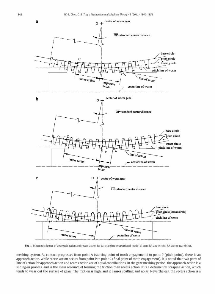
meshing system. As contact progresses from point A (starting point of tooth engagement) to point P (pitch point), there is anapproach action, while recess action occurs from point P to point C (final point of tooth engagement). It is noted that two parts ofline of action for approach action and recess action are of equal contributions. In the gear meshing period, the approach action is asliding-in process, and is the main resource of forming the friction than recess action. It is a detrimental scraping action, whichtends to wear out the surface of gears. The friction is high, and it causes scuffing and noise. Nevertheless, the recess action is a
Fig. 1. Schematic figures of approach action and recess action for (a) standard proportional tooth (b) semi RA and (c) full RA worm gear drives.
1842 W.-L. Chen, C.-B. Tsay / Mechanism and Machine Theory 46 (2011) 1840–1853
sliding-out meshing process to help keeping the rotation of worm gear drives in their respective directions, and friction is lower.Nature of the recess action is beneficial, tending to cold work the surfaces, smooth out the rough spots, and work-harden thecontact surface in the gear meshing process. This in turn increases the surface endurance limits of the material and the loadcapacity [1].
The RA gear can eliminate the amount of friction by reducing the approach action, or increasing the recess action. Fig. 1(c) is thefull RA worm gear meshing system obtained by having the pitch line of the worm tangent to the throat circle of the worm gear. Inthis case, the pitch circle and throat circle of the full RA worm gear are identical. The worm is made larger and the worm gear issmaller, so that the lead of worm is equal to the circular pitch of the worm gear at pitch circle or throat circle. This results in theexistence of only the recess action in the process of worm gear drivemating. As shown in Fig. 1(b) and (c), both semi RA and full RAworm gear drives have a change in the contact conditions between engaging teeth. Most or all of the contact occurs during therecess action of line of contact. Thus, they can eliminate the detrimental effects of the approach action. This results in lowermeshing torques and higher operating efficiency. It is frequently possible that the RAworm gear drive runs in a dry film lubricationin some cases whereas a conventional standard worm gear drive system would require a wet lubricant.
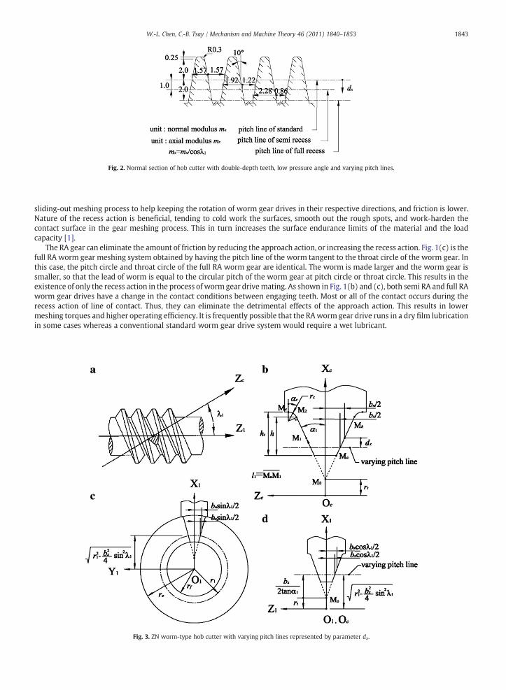
Fig. 3. ZN worm-type hob cutter with varying pitch lines represented by parameter dx.
Fig. 2. Normal section of hob cutter with double-depth teeth, low pressure angle and varying pitch lines.
1843W.-L. Chen, C.-B. Tsay / Mechanism and Machine Theory 46 (2011) 1840–1853
Another advantage of RA worm gears is to balance strength. In general, for the standard proportional tooth worm gear drive,the tooth thicknesses of worm and worm gear at pitch circle are the same. However, a long-addendum design together with aproportional increase in tooth thickness at the pitch line of the worm [1,13] makes the tooth thickness of the worm gear at pitchcircle is smaller for the RA worm gear drive, it makes the worm tooth stronger and the worm gear tooth weaker.
3. RA worm gears with double-depth teeth generated by different recess of hob cutters
RA worm gears can be manufactured with a standard hob cutter and hobbing machine, but consideration on varying pitchline of hob cutter with respect to the generated RA worm gears is needed. In this study, let's design the hob cutter differentfrom the conventional one. Fig. 2 shows the normal section of hob cutter that its tooth form is a straight-lined edge shapebased on the ZN worm-type of ISO classification. To design RA worm gear drives with double-depth teeth, the pressure angleof hob cutter is reduced from the normally used 20° and 22.5° to a minimum of 10° [2]. This should pay more attention on thechecking of the teeth of hob cutter and generated RA worm gear should not be pointed. The pitch lines of the hob cutter ingenerating semi RA and full RA worm gears become dx= 1.0 and 2.0 of normal modulus, mn (i.e. axial modulus mx=mn/cos λ1), below the middle of cutting tooth height, respectively, as shown in Fig. 2 where dx is the distance measured from themiddle of cutting blade height to the varying pitch line (also refer to Fig. 3(b) and (d)). Thus, tooth thicknesses of thegenerated semi RA and full RA worm gears at their normal pitch circles become 1.22 and 0.86mn, and their normal throat radiiare (T2+2)mn/2mm and T2mn/2mm, individually. Symbol T2 denotes the tooth number of the generated RA worm gear. Theabove design gives different proportional changes of addendum and dedendum of hob cutter in generating semi RA and fullRA worm gears. Especially, for a full RA worm gear, the pitch circle and throat circle are identical. Besides, the standardproportional tooth worm gear is a special case of the RA type worm gear when dx equals 0, no doubt, the pitch line of the hobcutter is at the middle of cutting tooth height. This gives that tooth thickness of the generated worm gear at its normal pitchcircle is 1.57mn, and normal throat radius is (T2+4)mn/2mm.
4. Equation of the ZN worm -type hob cutter
The ZN worm-type hob cutter with normal profile of straight-lined edge shape is chosen to generate the RA worm gear in thisstudy. A right-handed ZNworm-type hob cutter, as shown in Fig. 3, is chosen to generate RAworm gears in this study. The surfacesof ZN worm-type hob cutter can be cut by a blade. At first, the cutting blade is placed on the groove normal plane of the ZN worm-type hob cutter, as shown in Fig. 3(a). The blade, inclining with a lead angle λ1 , is performed a screw motion with respect to thehob cutter axis.
According to Fig. 3(b), the normal section of the cutting blade consists of straight-lined edge and circular tip, which generatethe tooth surface and fillet surface of the worm gear, respectively.
In Fig. 3(b), l1 denotes a design parameter of the cutting blade straight-lined edge surface, starting from the intersection pointMo of the two straight-lined edges to the end point Mb. And the moving point M1, represents any point on the cutting bladestraight-lined edge surface, moving from the initial pointMa to the end pointMb.MoMa denotes the shortest distance of the cuttingblade straight-lined edge surface, i.e. l1(min), while MoMb indicates the longest distance of the cutting blade straight-lined edgesurface, i.e. l1(max).α1 denotes the pressure angle formed by the straight-lined edge and the Xc-axis, as shown in Fig. 3(b). Thecutting blade width bx equals the normal groove width of the hob cutter, varying with the pitch line of the hob cutter in generatingRAworm gears, as explained in Section 3. In Fig. 3(c), symbols ro, r1 and rf represent the outside radius, pitch radius and root radiusof the ZN worm-type hob cutter, respectively.
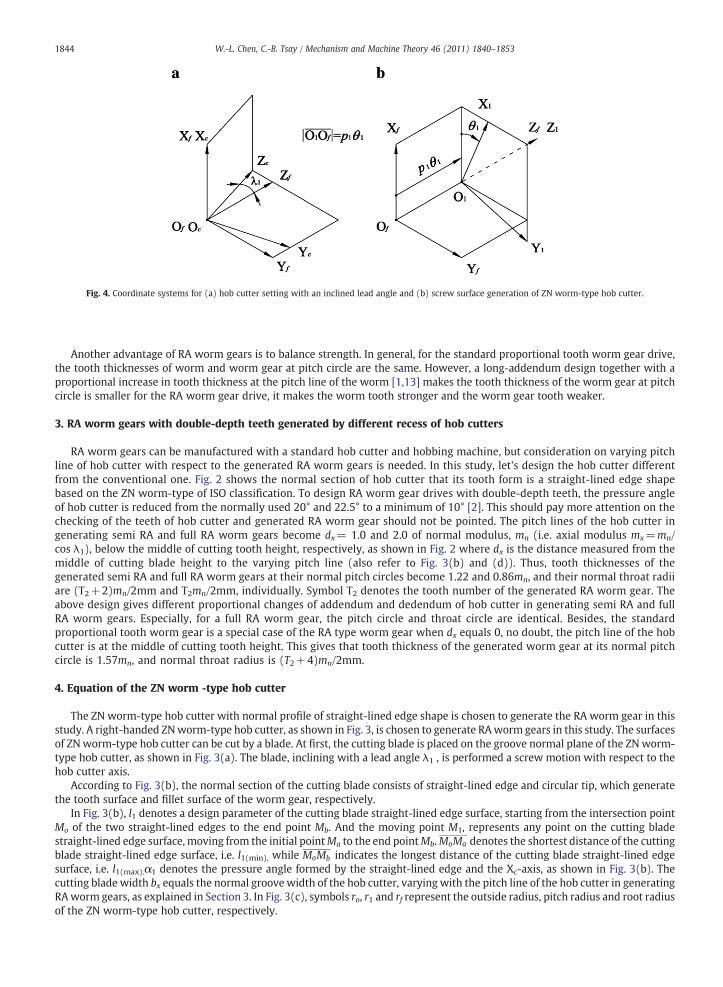
Fig. 4. Coordinate systems for (a) hob cutter setting with an inclined lead angle and (b) screw surface generation of ZN worm-type hob cutter.
1844 W.-L. Chen, C.-B. Tsay / Mechanism and Machine Theory 46 (2011) 1840–1853
Therefore, the generating line of cutting blade can be represented in coordinate system Sc(Xc, Yc, Zc) that fixed to the bladenormal plane, as shown in Fig. 3(b), as follows:
Rc =
rt + l1 cos α1
0� l1 sin α1
1
2664
3775; ð1Þ
where the upper sign of “±” sign denotes the left-side of cutting blade while the lower sign denotes the right-side of cutting blade.rt is the distancemeasured from the rotation center of ZNworm-type hob cutter O1 or Oc to pointMo, as shown in Fig. 3(b) and (d).Therefore, rt, bx, l1(min), l1(max) and h can be expressed as follows:
rt =
ffiffiffiffiffiffiffiffiffiffiffiffiffiffiffiffiffiffiffiffiffiffiffiffiffiffiffiffiffiffiffiffiffiffiffiffiffir21−
bx2
sin λ1
� �2s
− bx2 tan α1
; ð2Þ
bx = bn−2dx tanα1; ð3Þ
l1 minð Þ =1
2cosα1
bntan α1
−h� �
; ð4Þ
l1 maxð Þ =1
2cosα1
bntanα1
+ h� �
; ð5Þ
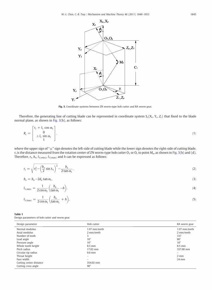
Fig. 5. Coordinate systems between ZN worm-type hob cutter and RA worm gear.
Table 1Design parameters of hob cutter and worm gear.
Design parameter Hob cutter RA worm gear
Normal modulus 1.97 mm/teeth 1.97 mm/teethAxial modulus 2 mm/teeth 2 mm/teethNumber of teeth 3 337Lead angle 10° 80°Pressure angle 10° 10°Whole tooth height 8.5 mm 8.5 mmPitch radius 17.02 mm 337.00 mmCircular tip radius 0.6 mm –
Throat height – 2 mmFace width – 24 mmCutting center distance 354.02 mmCutting cross angle 90°
1845W.-L. Chen, C.-B. Tsay / Mechanism and Machine Theory 46 (2011) 1840–1853

and
h = ht−rc 1−sin α1ð Þ; ð6Þ
where bn is the blade width at the middle of cutting blade height, and bn=πmn/2, h and ht denote straight-lined edge height andwhole height of the cutting blade, respectively, and rc represents the cutting blade tip radius, and dx is the distance measured fromthe middle of cutting blade height to the varying pitch line of the hob cutter. A special case is dx=0 mm for generating thestandard proportional tooth worm gear.
Similarly, the circular tip of cutting blade can also be expressed in coordinate system Sc as follows:
R cð Þc =
rt +bn
2 tanα1+
h2
+ rc cos αc− sin α1ð Þ
0
� bn2
+h tanα1
2+ rc cos α1− sin α cð Þ
� �1
2666666664
3777777775; ð7Þ
Fig. 6. Partial worm gear drive tooth profiles of (a) standard proportional teeth (b) semi RA teeth and (c) full RA teeth.
1846 W.-L. Chen, C.-B. Tsay / Mechanism and Machine Theory 46 (2011) 1840–1853
where 0≤αc≤90∘−α1, and αc denotes the angular design parameter of hob cutter circular tip. The moving point M2 representsany point on the cutting blade circular tip surface moving from the initial point Mc to the end point Mb.
Fig. 4 shows the relationship among the coordinate systems Sc(Xc, Yc, Zc), S1(X1, Y1, Z1) and Sf(Xf, Yf, Zf), where Sc is the bladecoordinate system, coordinate system S1 is rigidly connected to the hob cutter tooth surface, and Sf is the reference coordinate system.The inclined angle λ1, formed by axes Zc and Zf, is the lead angle of hob cutter. The tooth surface equation of the ZN worm-type hobcutter can be obtained by considering the blade coordinate system (i.e.Sc) performs a screw motion with respect to the fixedcoordinate system Sf. This can beachievedby applying the followinghomogeneous coordinate transformationmatrix equation:
R1 = M1f MfcRc = M1cRc; ð8Þwhere
M1c =
cos θ1 cos λ1 sin θ1 − sin λ1 sin θ1 0− sin θ1 cos λ1cos θ1 − sin λ1 cos θ1 0
0 sin λ1 cos λ1 −p1θ10 0 0 1
2664
3775; ð9Þ
and p1 indicates the lead-per-radian revolution of the hob cutter surface, and θ1 denotes the rotational angle of the hob cutter inrelevant screw motion. Substituting Eqs. (1) and (9) into Eq. (8), the straight-line edge surface equation of ZN worm-type hobcutter R1 can be represented in coordinate system S1 as follows:
R1 =
rt + l1 cos α1ð Þcos θ1 ∓ l1 sin λ1 sin α1 sin θ1− rt + l1cos α1ð Þsin θ1 ∓ l1 sin λ1 sin α1 cos θ1
� l1 cos λ1 sin α1− p1θ11
2664
3775: ð10Þ
Similarly, substituting Eqs. (7) and (9) into Eq. (8), the circular tip surface equation of the ZN worm-type hob cutter R1(c) can
also be obtained as follows:
R cð Þ1 =
cos θ1 rt +bn
2 tanα1+
h2
+ rc cos αc− sin α1ð Þ� �
∓
sin λ1 sin θ1bn2
+h tanα1
2+ rc cos α1−sin αcð Þ
� �
− sin θ1 rt +bn
2 tan α1+
h2
+ rc cos αc−sin α1ð Þ� �
∓
sin λ1 cos θ1bn2
+h tanα1
2+ rc cos α1−sin αcð Þ
� �
cosλ1bn2
+htanα1
2+ rc cosα1−sinαcð Þ
� �−p1θ11
26666666666666666664
37777777777777777775
: ð11Þ
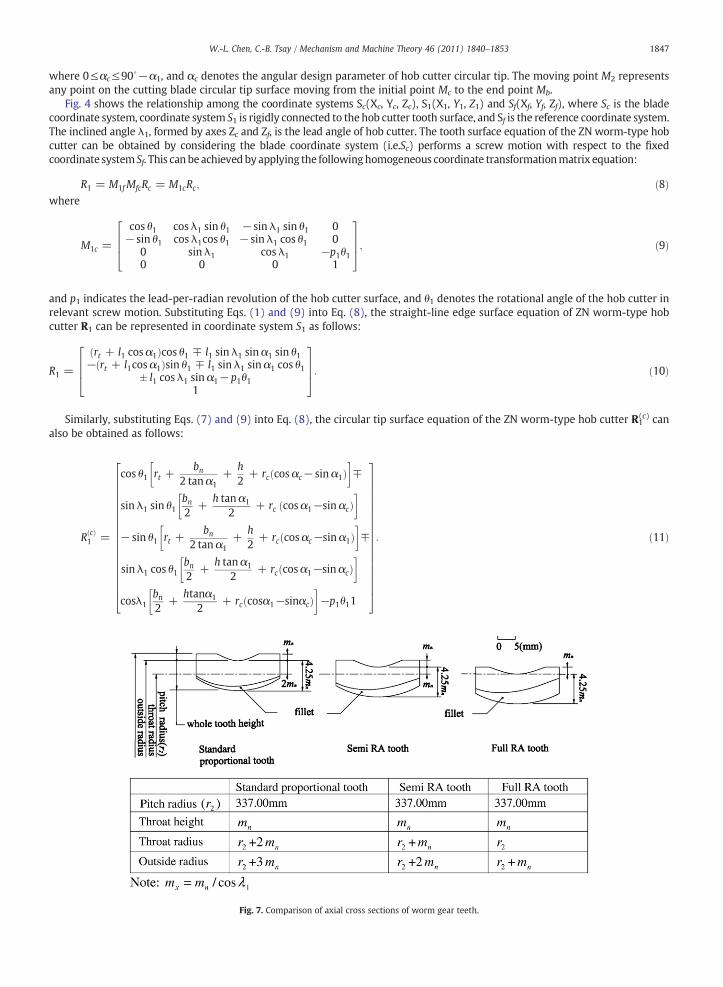
Fig. 7. Comparison of axial cross sections of worm gear teeth.
1847W.-L. Chen, C.-B. Tsay / Mechanism and Machine Theory 46 (2011) 1840–1853
5. Normal equation of the ZN worm-type hob cutter
The normal vector of the hob cutter straight-lined edge surface, represented in the coordinate systemS1, can be obtainedby:
N1 =∂R1
∂l1×
∂R1
∂θ1; ð12Þ
where
∂R1
∂l1=
cos α1 cos θ1 ∓ sin α1 sin λ1 sin θ1−cos α1 sin θ1 ∓ sin α1 sin λ1 cos θ1
� sin α1 cos λ1
24
35; ð13Þ
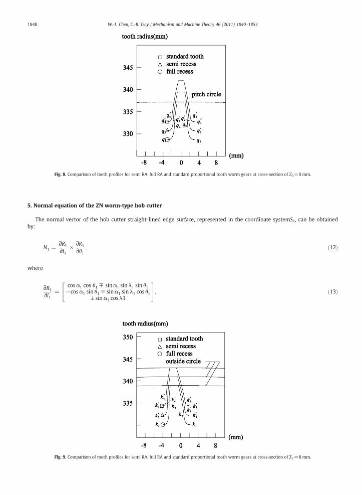
Fig. 8. Comparison of tooth profiles for semi RA, full RA and standard proportional tooth worm gears at cross-section of Z2=0 mm.
Fig. 9. Comparison of tooth profiles for semi RA, full RA and standard proportional tooth worm gears at cross-section of Z2=8 mm.
1848 W.-L. Chen, C.-B. Tsay / Mechanism and Machine Theory 46 (2011) 1840–1853
and
∂R1
∂θ1=
− rt + l1 cos α1ð Þsinθ1 ∓ l1 sin λ1 sin α1 cosθ1− rt + l1 cos α1ð Þcos θ1 � l1 sin λ1 sin α1 sinθ1
−p1
24
35: ð14Þ
Similarly, the normal vector of the hob cutter circular tip surface, also represented in the coordinate system S1, can be obtainedby:
N cð Þ1 =
∂R cð Þ1
∂αc×
∂R cð Þ1
∂θ1; ð15Þ
where
∂R cð Þ1
∂αc=
rc −sin αc cos θ1 � sin λ1 cos αc sin θ1ð Þrc sin αc sin θ1 � sin λ1 cos αc cos θ1ð Þ
−rc cos λ1 cos αc
24
35; ð16Þ
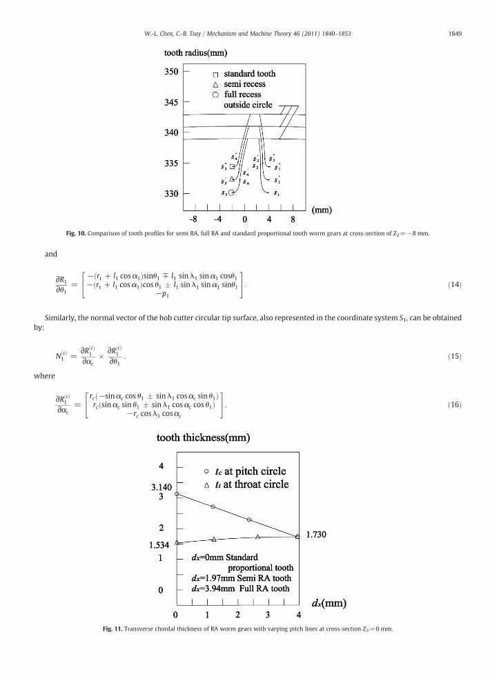
Fig. 10. Comparison of tooth profiles for semi RA, full RA and standard proportional tooth worm gears at cross-section of Z2=−8 mm.
Fig. 11. Transverse chordal thickness of RA worm gears with varying pitch lines at cross-section Z2=0 mm.
1849W.-L. Chen, C.-B. Tsay / Mechanism and Machine Theory 46 (2011) 1840–1853
and
∂R cð Þ1
∂θ1=
−sin θ1 rt +bn
2 tan α1+
h2
+ rc cos αc − sin α1ð Þ� �
∓
sin λ1cos θ1bn2
+h tan α1
2+ rc cos α1− sin αcð Þ
� �
− cos θ1 rt +bn
2 tan α1+
h2
+ rc cos αc− sin α1ð Þ� �
�
sin λ1 sin θ1bn2
+h tanα1
2+ rc cos α1−sin αcð Þ
� �
−p1
26666666666666666664
37777777777777777775
: ð17Þ
6. Mathematical equation of the generated RA worm gears
Fig. 5 shows the schematic generating mechanism of hob cutter and RA worm gear. Coordinate systems Sp(Xp, Yp, Zp)and Sg(Xg,Yg, Zg) are reference coordinate systems for the hob cutter and generated RA worm gear, respectively. Coordinate system S1(X1, Y1,Z1) of the hob cutter rotates through an angle ϕ1 counterclockwise with respect to the reference coordinate system Sp. Similarly,coordinate system S2(X2, Y2, Z2) of the generated RA worm gear rotates through an angle ϕ2 counterclockwise with respect to thereference coordinate system Sg. Reference coordinate systems Sp and Sg are formed a cutting cross angle γ1 of the hob cutter andgenerated RA worm gear. O1O2 =C1 is the center distance of the hob cutter and generated RA worm gear, i.e.C1= r1+r2, where r1and r2 are the pitch radii of hob cutter and generated RA worm gear, respectively.
The locus equation of hob cutter surface can be obtained by applying the following homogeneous coordinate transformationmatrix equation:
R2 = M2gMgpMp1R1 = M21R1; ð18Þwhere
M21 =
a11 a12 sin γ1 sin �2 −cos �2 C1a21 a22 sin γ1 cos �2 sin �2 C1
−sin γ1 sin �1 −sin γ1 cos �1 cos γ1 00 0 0 1
2664
3775; ð19Þ
and
a11 = + cos �1 cos �2 + cos γ1 sin �1 sin �2;a12 = −sin �1 cos �2 + cos γ1 cos �1 sin �2;a21 = −cos �1 sin �2 + cos γ1 sin �1 cos �2;a22 = + sin �1sin �2 + cos γ1cos �1cos �2:
ð20Þ
By substituting Eqs. (10), (11) and (19) into Eq. (18), the hob cutter locus equations of straight-lined edge and circular tip,expressed in coordinate system S2, are obtained as follows:
R2 =
a11 X1 + a12 Y1 + sin γ1 sin �2 Z1− cos �2 C1a21 X1 + a22 Y1 + sin γ1 cos �2 Z1 + sin �2 C1− sin γ1 sin �1 X1− sin γ1 cos �1Y1 + cos γ1 Z1
1
2664
3775; ð21Þ
where �2 = T1T2�1, and T1, T2, ϕ1, and ϕ2 are tooth numbers and rotational angles of the hob cutter and generated RA worm gear,
respectively.
7. Equation of meshing between the hob cutter and generated RA worm gears
In the worm gear generation process, the hob cutter and generated RAworm gear tooth surfaces are never embedded into eachother, i.e. the relative velocity of the generated RA worm gear with respect to the hob cutter is perpendicular to their commonnormal vector N1 at any cutting instant. Therefore, the equation of meshing of the hob cutter and generated RA worm gear can beexpressed as follows [12]:
N1•V1ð Þ
12 = N1• V 1ð Þ1 −V 1ð Þ
2
� �= 0; ð22Þ
where V1(1) and V2
(1) denote the velocities of the hob cutter and generated RA worm gear, respectively, and superscript “ (1) ”
indicates the velocities are represented in coordinate system S1.
1850 W.-L. Chen, C.-B. Tsay / Mechanism and Machine Theory 46 (2011) 1840–1853
According to Fig. 5, the relative velocity of the generated RAworm gearwith respect to the hob cutter represented in coordinatesystem S1, can be obtained by:
V 1ð Þ12 = ω 1ð Þ
1 −ω 1ð Þ2
� �× R1−O1O2 1ð Þ × ω 1ð Þ
2 ; ð23Þ
where ω1(1) and ω2
(1) are the angular velocities of the hob cutter and the generated RA worm gear, respectively, and they can beexpressed in their respectively coordinate systems S1 and Sg as follows:
ω 1ð Þ1 = 0 0 1½ �Tω1; ð24Þ
and
ω gð Þ2 = 0 0 1½ �Tω2: ð25Þ
Angular velocity ω2(g)can be also represented in coordinate system S1, by applying the following coordinate transformation
matrix equation:
ω 1ð Þ2 = L1pLpgω
gð Þ2 = L1gω
gð Þ2 ; ð26Þ
where
L1g =cos �1 cos γ1 sin �1 − sin γ1 sin �1
− sin �1 cos γ1 cos �1 − sin γ1 cos �10 sin γ1 cos γ1
24
35: ð27Þ
Substituting Eqs. (25) and (27) into Eq. (26), the angular velocity of the generated RA worm gear, represented in coordinatesystem S1, can be obtained by:
ω 1ð Þ2 = ω1
−m21 sin γ1 sin �1−m21 sin γ1 cos �1
m21 cos γ1
24
35; ð28Þ
where m21=ϕ2/ϕ1 is the angular velocity ratio of generated RA worm gear to hob cutter.Similarly, according to Fig. 5, vector O1O2 can be obtained and expressed in coordinate system S1 by
O1O21ð Þ = L1pO1O2
pð Þ; ð29Þ
where
O1O2pð Þ = C1 0 0½ �T ; ð30Þ
and
L1p =cos �1 sin �1 0−sin �1 cos �1 0
0 0 1
24
35: ð31Þ
Substituting Eqs. (30) and (31) into Eq. (29), vector O1O2 is represented in coordinate system S1 as follows:
O1O21ð Þ =
cos �1 C1− sin �1C1
0
24
35: ð32Þ
Again, substituting Eqs. (10), (11), (24), (28), and (32) into Eq. (23) yields:
V 1ð Þ12 = ω1
m21 cos γ1− 1ð ÞY1 + m21 sin γ1 cos �1 Z1 + cos γ1 sin �1 C1ð Þ− m21 cos γ1− 1ð ÞX1 + m21 − sin γ1 sin �1 Z1 + cos γ1 cos �1 C1ð Þ
m21 sin γ1 − cos �1 X1 + sin �1 Y1 + C1ð Þ
24
35: ð33Þ
1851W.-L. Chen, C.-B. Tsay / Mechanism and Machine Theory 46 (2011) 1840–1853
Eq. (33) expresses the relative velocity of the hob cutter and generated RA worm gear at their common cutting point M2 atevery cutting instant. According to theory of gearing, the common surface normal N1 is perpendicular to relative velocity V12
(1).Therefore, substituting Eqs. (12), (15) and (33) into Eq. (22) obtains:
f l1; θ1; �1 �2ð Þð Þ = m21 cos γ1−1ð ÞY1 + m21 sin γ1 cos �1 Z1 + cos γ1sin �1 C1ð Þ½ �Nx1 +
− m21 cos γ1−1ð ÞX1 + m21 − sin γ1 sin �1 Z1 + cos γ1cos �1 C1ð Þ½ �Ny1 +
m21 sin γ1 − cos �1 X1 + sin �1 Y1 + C1ð Þ½ �Nz1 = 0; ð34Þ
where Nx1, Ny1 and Nz1 are components of the normal vector of hob cutter.Eq. (34) is the so-called equation of meshing of the hob cutter and generated RA worm gear. This equation keeps them in
tangency at every instant during the cutting process. Therefore, the working tooth and fillet surface equations of the generated RAworm gear can be obtained by considering the hob cutter locus equations of straight-lined edge and circular tip as well as theequations of meshing, i.e. Eqs. (21) and (34), simultaneously.
8. Computer graphs of the generated RA worm gears with double-depth teeth
The tooth surface equation of the generated RA worm gear proposed herein can be verified by plotting the worm gear profilewith computer graphics. Since the tooth surface equation is non-linear, therefore, solving by numerical analysis method is needed.
Table 1 lists some design parameters of the hob cutter and generated RA worm gear. Based on the developed mathematicalmodel of the worm gear tooth surface, three-dimensional tooth profiles of semi RA, full RA and standard proportional tooth wormgears are plotted in Fig. 6. A series of worm gears, partial (15/337) teeth are plotted, are of the same pitch circle and throat height,but with different throat circle and outside circle. Points D and E indicate the penetration points of pitch circle with partial(15/337) teeth, while points F and G are the intersection points of the throat circle with generated worm gear. For a full RA wormgear, pitch circle and throat circle pass through the throat of the worm gear, as shown in Fig. 6(c). In the other words, pitch circleand throat circle are identical. But for the standard proportional tooth worm gear (i.e. special case of RA worm gear with dx=0),pitch circle passes through the middle of the tooth height, as shown in Fig. 6(a).
9. Tooth profile comparisons of the generated RA worm gears with double-depth teeth
The worm gear design parameters are chosen the same as those listed in Table 1. A series of worm gears, semi RA, full RA andthe standard proportional tooth, are generated by using varying pitch lines (refer to Figs. 2 and 3), dx=1.97 mm, 3.94 mm and0 mm, respectively. Axial cross sections of this series of worm gear teeth are shown in Fig. 7. Figs. 8, 9 and 10 show the toothprofiles of the generated RA worm gears with double-depth teeth at cross sections of Z2=0 mm, Z2=8 mm, and Z2=−8 mm(refer to Fig. 6), respectively.
Fig. 8 shows the tooth profiles of a series of worm gears at cross section of Z2=0 mm. It is noted that for the full RA worm gear,its pitch circle and throat circle become identical (also refer to Figs. 6(c) and 7), only dedendum part of working height exists, andaddendum part shrinks to zero, because of full recess design. Additionally, the fillet curves q1q2 and q3q4 of the full RA worm gearthat generated by hob cutter are larger than those of two others, thus theworking height is smaller. And, the standard proportionaltooth worm gear is easier to become pointed teeth than the full RA type worm gear. Fig. 8 also shows that the transverse chordaltooth thickness of the full RA worm gear at pitch circle is the smallest.
Fig. 9 shows the tooth profiles having different outside circles at Z2=8 mm. A series of worm gears have the constant leadangle across the whole face width. The standard proportional tooth worm gear has a thicker tooth, and the full RA type worm gearhas a thinner tooth. Comparisons of Figs. 8 and 9 show that the thickness of standard proportional worm gear tooth profile is largerand its fillet curves k1"k2" and k3
"k4" are smaller at the end of face width Z2=8 mm. Comparisons of Figs. 8, 9 and 10 show that the RA
worm gear fillet curves are the largest ones at Z2=0 mm. A full RA worm gear tooth most likes a column across the whole facewidth.
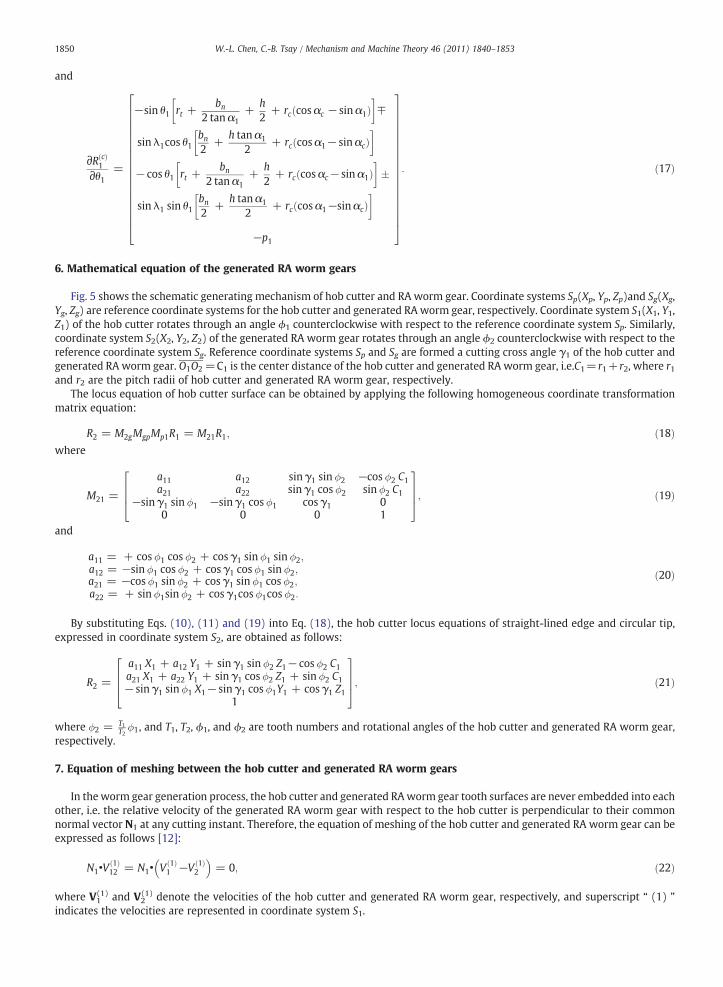
Fig. 11 numerically shows the transverse chordal tooth thickness at pitch circle and throat circle, respectively, at the crosssection Z2=0 mm. It is found that the tooth thickness at pitch circle, tc=3.140 mm, is the largest for the standard proportionaltooth worm gear than those for semi RA and full RA types. Reversely, the tooth thickness of the standard proportional tooth wormgear at throat circle, tt=1.534 mm, becomes the smallest. It is noted that the tooth thicknesses at pitch circle and throat circle arethe same, tc= tt=1.730 mm, for the full RA worm gear because its pitch circle and throat circle are identical.
10. Conclusion
The mathematical model of the generated RA worm gear with double-depth teeth is developed according to the gear generationmechanismand the theory of gearing. The tooth surface equation of the RAwormgear is also expressed in terms of design parametersof the ZNworm-type hob cutter. Computer graphs of semi RA, full RA and the standard proportional toothwormgears are plotted. It isfound that thepitch circle and throat circle of the full RAwormgear are identical. At cross-sectionof tooth cross-section of toothwidth,i.e. Z2=0mm, the addendumpart of the full RAworm gear shrinks to zero. Besides, the fillet curve of the full RAworm gear is longer
1852 W.-L. Chen, C.-B. Tsay / Mechanism and Machine Theory 46 (2011) 1840–1853
than those of semi RA and standard proportional wormgears. The transverse chordal tooth thickness of the full RAwormgear at pitchcircle is smaller than thoseof the semiRAand standardproportionalwormgears. The results of this studywouldbemost helpful to thefurther studies of contact ellipse, contact path, kinematic errors (KEs), and stress analysis of the RA worm gear.
References
[1] E.K. Buckingham, Here's How to Design Full and Semi-Recess Action Gears, Gear Design and Application, in: N.P. Chironis (Ed.), Product EngineeringMagazine, 1971, pp. 136–143.
[2] E.K. Buckingham, 3 Are Familiar, 3 Little Known in this Guide to Worm Gear Types, Gear Design and Application, in: N.P. Chironis (Ed.), Product EngineeringMagazine, 1971, pp. 69–78.
[3] W.P. Crosher, Design and Application of the Worm Gear, ASME Press, New York, 2002.[4] J.E. Shigley, C.R. Mischke, Mechanical Engineering Design, 5th ed McGraw-Hill, NY, 1989.[5] Y. Yang, Computer-aided design of recess-action gears, Computers in Engineering, Proceedings of the International Computers in Engineering Conference, 3,
1985, pp. 445–449.[6] R.E. Siegal, H.H. Mabie, Determination of hob-offset values for nonstandard spur gears based on maximum ratio of recess to approach action, Appl. Mech.
Conf., 3rd, Proc., Pap., Stillwater, 1973.[7] H. Meng, Q. Chen, Research into the scuffing loading capacity of all-recess action gears, Proceedings of the Sixth World Congress on the Theory of Machines
and Mechanisms, 1984, pp. 895–901.[8] E. Wildhaber, A new look at worm gear hobbing, Proceedings of American Gear Manufactures Association Conference, Virginia, 1954.[9] H. Winter, H. Wilkesmann, Calculation of cylindrical worm gear drives of different tooth profiles, J. Mech. Des., Trans. ASME 103 (1981) 73–82.
[10] M. Bosch, Economical Production of High Precision Gear Worms and Other Thread Shaped Profiles by Means of CNC-Controlled Worm and Thread GrindingMachines, Klingelnberg Publication, Germany, 1988, pp. 3–19.
[11] H.S. Fang, C.B. Tsay, Mathematical model and bearing contacts of the ZN-type worm gear sets cut by oversize hob cutters, Mech. Mach. Theor. 35 (12) (2000)1689–1708.
[12] F.L. Litvin, A. Fuentes, Gear Geometry and Applied Theory, second ed. Cambridge University Press, 2004.[13] D.W. Dudley, Handbook of Practical Gear Design, CRC Press, 1994.
1853W.-L. Chen, C.-B. Tsay / Mechanism and Machine Theory 46 (2011) 1840–1853