Mechanics of Collapse of WTC Towers Clarified by Recent ... · PDF fileMechanics of Collapse...
6
Mechanics of Collapse of WTC Towers Clarified by Recent Column Buckling Tests of Korol and Sivakumaran Jia-Liang Le and Zden ˇ ek P. Ba ˇ zant Report SEGIM No. 16-08c Department of Civil and Environmental Engineering Northwestern University Evanston, Illinois 60208, USA September 4, 2016
Transcript of Mechanics of Collapse of WTC Towers Clarified by Recent ... · PDF fileMechanics of Collapse...

Mechanics of Collapse of WTC Towers Clarified by
Recent Column Buckling Tests of Korol and
Sivakumaran
Jia-Liang Le and Zdenek P. Bazant
Report SEGIM No. 16-08c
Department of Civil and Environmental Engineering
Northwestern University
Evanston, Illinois 60208, USA
September 4, 2016
Mechanics of Collapse of WTC Towers Clarified by RecentColumn Buckling Tests of Korol and Sivakumaran
Jia-Liang Le
1, and Zdenek P. Bazant
2
Abstract: The previously formulated model of the gravity-driven collapse of the twin towers of the
World Trade Center on 9/11/2001 was shown to match all the existing observations, including the video
record of the crush-down motion of the top part of tower during the first few seconds, the seismically
recorded duration of collapse, the size distribution of particles caused by impact comminution of concrete
floor slabs, the loud booms due to near-sonic lateral ejection velocity of air and dust, and precedence of
the crush-down collapse mode before the crush-up. Nevertheless, di↵erent degrees of ductility, fracturing
and end support flexibility of WTC columns could lead to an equally good match of these observations
and remained uncertain, due to lack of test data. Recently, Korol and Sivakumaran reported valuable
experiments that allow clarifying this uncertainty. They reveal that, under the assumptions of rigid end
supports and unlimited ductility (or no fracturing), the energy dissipation in the WTC columns would have
been at maximum 3.5-times as large as that calculated by the plastic hinge mechanism normally considered
for small deflection buckling. This increase would still allow close match of all the aforementioned obser-
vations except for the first two seconds of the video. The proper conclusion from Korol and Sivakumaran’s
tests, based on close matching of the video record, is that the fracturing of columns and the flexibility
of end restraints must have significantly reduced the energy dissipation in columns calculated under the
assumptions of no fracture and no end restraint flexibility.
Keywords: Buckling, Collapse, Ductility, Fracture
Introduction
Previous studies [4, 3, 2, 6] led to a rigorous mathematical model which showed that a gravity drivencollapse of the twin towers of the World Trade Center (WTC) in New York on 9/11/2001 was inevitable.The model showed that, at the beginning of collapse, the energy dissipation by plastic buckling ofcolumns was the main mechanism of resistance. It also explained why the crush-down must havepreceded the crush-up, and why air and debris were ejected laterally at almost the sound velocity,inevitably making loud booms and big dust clouds. It gave the correct size distribution of the particlesfrom impact comminution of the concrete floor slabs, and agreed closely with the observed duration ofcollapse. Further it explained why the towers did not topple sideway like a tree [4], and why the motionobserved in the initial video was virtually smooth, without any velocity fluctuation detectable by eye[6]. However, for lack of test data, it left unanswered two questions: 1) Didn’t extensive fracturingof the columns limit significantly the ductility of steel? And 2) didn’t flexibility and plasticity of thespandrel plates reduce the rotations, and thus the energy dissipation, in the plastic hinges at columnends? And if so, by how much?
Korol and Sivakumaran [5] recently presented valuable experimental results that allow answer-ing these questions. They tested reduced-scale extruded H-shaped aluminum columns without endrestraints which exhibited virtually unlimited ductility, i.e., no fracture. They found that the dissipa-tion by a 180� rotation of the plastic hinge at mid height of the column was about 3.5-times as largeas that calculated in [4] by extrapolating from small rotations the work of plastic bending momentacting on a planar cross section. This extrapolation ignored the local buckling and folding of columnflanges, and large tensile flange extension, as revealed by these tests (Fig. 1).
1Associate Professor, Department of Civil, Environmental, and Geo- Engineering, University of Minnesota, Minneapo-
lis; Email: [email protected].
2Distinguished McCormick Institute Professor and Walter P. Murphy Professor, Department of Civil and Environ-
mental Engineering, Northwestern University, Illinois; Email: [email protected]; Corresponding author.
1

a) b)
4 Journal of Structures
Figure 3: Photographs of SR 42 specimen loaded well into thepostmaximum range.
specimen SR 42 in the testingmachine in postmaximum loadconditions. Continued loading led to local buckling of theflanges on the compression side of the plastic hinge. Figure 4shows the folds that form on the compression side of theplastic hinge associated with specimen SR 35. All seven testspecimens exhibited this compression flange local bucklingfollowed by folding. Such contact of the insides of the flangeswas noted for all specimens and is shown in Figure 5 whichwas assembled after completion of the experimental program.In each test the experiment was terminated once it wasevident that flanges above and below the hinge were incontact with one another. Had we continued the test beyondcontact of the flanges, the residual resistance would continueeven with such severe folding, since another fold above orbelow the original can occur, as noted in crush tests onsquare hollow sections [8]. Continued testing might haveeven shown a rise of load resistance with augmented energyabsorption. However, attempting to include such a clashof flange-on-flange was deemed to be beyond the scope ofreassessing the plastic hinge model for energy dissipation ofaxially loaded columns.
Experimental Results of H-Shapes Subject to Axial Loading.Figure 6 shows the load-displacement plots from the com-puter data generated during testing of all seven specimens.For example, the specimen SR33, which had an original
Figure 4: Compression flange folds of SR 35 in a state of largedisplacement.
Figure 5: Specimens after test completion.
length of 511mm, reached a maximum load of 124 kN, whichoccurred at an axial displacement of 15.1mm. This wasfollowed by flange buckling at mid-height and a consequentsevere drop-off in load resistance as the upper cross headmovement progressed. It is evident that there is a pre-cipitous loss of strength by about an order of magnitudecompared with the maximum strength values noted in thediagrams in Figure 6 and in Table 1. For large !!/"! ratiosthis result is to be expected since it is well known thataxially compressed unsupported flanges buckle elastically atmuch lower stresses than do those that have connecting
6 Journal of Structures
(a)
L
L!
"
(b)
Figure 7: Experimental and idealized plastic-hinged column at maximum displacement.
elements [9], a reference which simply validates the work ofmany outstanding researchers over recent decades. But evenin the inelastic response range, the importance of the buck-ling plate coefficient with respect to boundary conditions forclassification of sections into design categories is dependenton both geometrical and material properties [10].
The establishment of the amount of energy associatedwith converting a straight column into one that has a kink atmid-height requires knowledge of its load-displacement rela-tionship. This was achieved via instrumentation describedearlier linking the loads to averaged LVDT readings ofcrosshead displacements. The columns 3 and 4 given inTable 1 show the peak loads and the peak displacements,respectively, observed in each test. The energy absorbedduring an entire displacement range is, of course, the areaunder the curve and is summarized in Column 5 of Table 1.Note that the energy dissipated by the axially loaded columnsranged from a high energy of 8.19 kN⋅m to a low energy of6.78 kN⋅m.The other pertinent information noted in Figure 6is the average load resistances exhibited by the columnstested, which have been summarized in Column 6 of Table 1.Data from the seven plots, and as summarized in the Table 1,suggests that as the slenderness ratio increases, the averageload of resistance decreases, that is, reducing from 20 kN(SR 33) to 12.7 kN (SR 42). Of course, definitive conclusionscannot be made in this regard, but it does suggest thatpostbuckling resistance would decrease as a given columnsection increases in length, inferring the importance ofslenderness ratio in assessing the energy dissipation potentialfor columns subjected to displacements of the order of theirlengths.
The final lengths of the test specimens were derived basedon the original lengths and the peak axial displacements andare given in Column 7—Table 1. For example, specimen SR35which had an original length of 549mm was axially loadedfor a maximum displacement of 422mm, resulting in a finallength of specimen of 127mm. In this case the crush testwas conducted until the displacement into a scissors-shapedconfiguration of the column reached approximately 77% ofthe original height (422/549). Figure 7 shows specimen SR35
after test. The plastic hinge rotation associated with sucha displacement can be estimated from the formula " =# − 2sin−1(%"/%), where " is the angle through which thetwo segments are rotated, which represents the localizedrotation at mid-height associated with Δmax (see Figure 7).The plastic hinge rotations for all seven specimens werecalculated and are tabulated in Column 8 of Table 1. Note thatthe rotations are expressed in radians and the correspondingangles are given within brackets. As shown in Column 8of Table 1, the experimental hinge rotations, that is, thescissors angle just at the point of flange clashing, are in therange of 150–160∘.3. Discussion and Conclusions
The energy dissipated in a plastic hinge undergoing a plasticrotation " is given as '$", where '$ is plastic momentresistance based on the assumption that the cross-sectionwill indeed reach the plastic moment prior to flange localbuckling. Since bending in these experiments is about theminor axis, we need to compute the corresponding plasticsection modulus, ($, for the section shown in Figure 1. Foran idealized H-shape that neglects the corner radius effects,the minor-axis plastic section modulus, computed using theexpression ($ = 1/4[)2% ⋅ 2*% + *2& ⋅ (+ − 2*%)], is 13,162mm3.Since the yield stress based on a 0.2% offset was determinedto be 58MPa, we compute the fully plastic moment aboutthe minor axis to be 0.763 kN⋅m. We then determine theenergy dissipation for the plastic hinge by multiplying by "for each of our tests. The plastic hinge model-based energyresults are given in Column 9 of Table 1. Column 10 ofTable 1 compares the experimental energy values with thecorresponding energy values based on the hinge model. It isevident that regardless of the slenderness ratio, the ratio ofexperimental amount of energy absorbed by an H-columnunder pure axial compression is three to four times greaterthan what the plastic hinge model analysis predicts.
It must be acknowledged that the plastic hinge modelcalculations employed a yield stress value of 58MPa, which
c)
Zone of high energy dissipation
Figure 1: Experiments by Korol and Sivakumaran: a)-b) specimen during the test, and c) finaldeformation shape of the specimen (Source: Fig. 3 and Fig 7a in Korol Sivakumaran [5]).
Simplifications of Original Analysis Due to Lack of Data
Because of uncertainties due to lack of experimental data, the original analysis of WTC collapse [4, 3]introduced three simplifying assumptions:
a) perfect ductility of steel, with no fracture,b) constancy of the bending moment in the plastic hinge up to 180� rotation, andc) rigid support of column ends.
With these assumptions and for the plastic bending moment based on the standard engineeringtheory of bending [7, Sec.8.6] (with the cross section remaining planar), it was found that the energy,Wd, dissipated by buckling of the columns of the first collapsing floor represented about 1/8 of thekinetic energy Mv20/2 of the impacting mass M of the upper part of tower [4], v0 being the impactvelocity (0.19 m/s). According to these original assumptions, the buckling of the columns of the firstimpacted floor reduces the kinetic energy to Mv21/2 = (1 � 1
8)Mv20/2. So, the velocity after impactdrops to v1 = v0
p7/8 = 0.935 v0.
By directly applying Korol and Sivakumaran’s results [5] to WTC towers, the energy dissipationcalculated by the plastic hinge mechanism [7, Sec.8.6] (according to the foregoing three assumptions)would have to increase by 3.5-times, i.e., Mv21/2 = (1 � 7
16)Mv20/2, which gives v1 = 0.750 v0. Obvi-ously, this updated estimate again indicates a continuing collapse. In no way the energy dissipation inthe columns of one floor could be large enough to exceed Mv20/2, which would be necessary to arrestthe gravity-driven collapse.
After the crushing front advances by about ten floors, the collapsing mass grows significantly andthe kinetic energy of the falling mass dwarfs the energy dissipated by the columns. It then ceasesto matter whether or not the dissipation by plastic buckling is tripled. Therefore, the calculationsof the overall duration of collapse, of the velocity of expelling air and debris shedding, and of theimpact comminution of concrete slabs into particles, would not change beyond the range of error inthe observations made.
Non-Rigid Restraints at Column Ends
The Korol and Sivakumaran’s columns developed no plastic hinges at the ends. Their end supportshad a flat free contact with the loading platens rather than perfect restraint. Beginning with a certain
2
a)
Floor
Floor
Floor
Columns
Spandrel plate
Fig. 2 b) c)
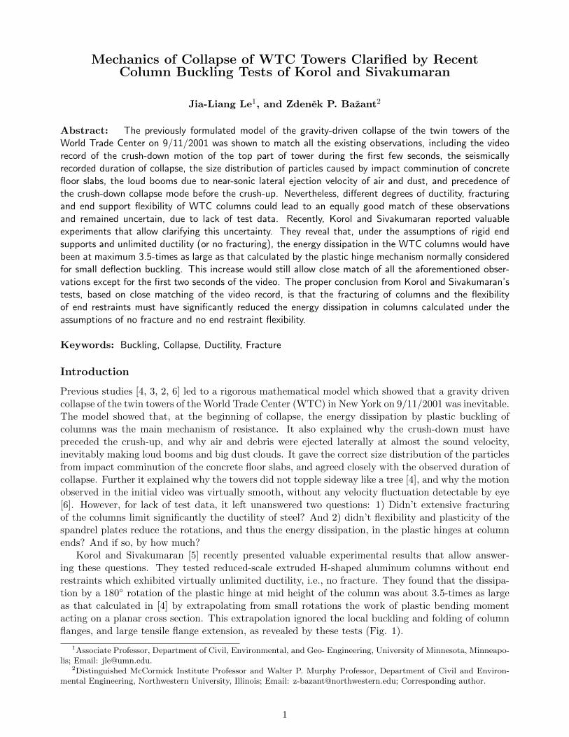
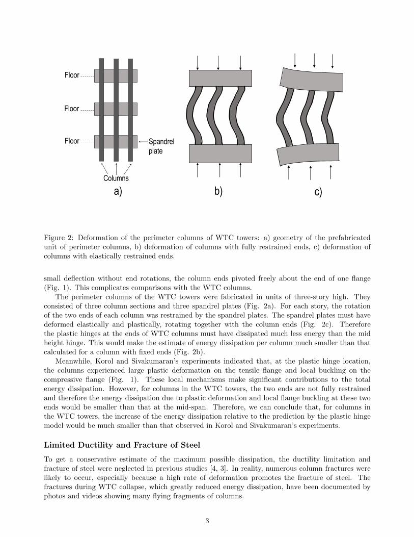
Figure 2: Deformation of the perimeter columns of WTC towers: a) geometry of the prefabricatedunit of perimeter columns, b) deformation of columns with fully restrained ends, c) deformation ofcolumns with elastically restrained ends.
small deflection without end rotations, the column ends pivoted freely about the end of one flange(Fig. 1). This complicates comparisons with the WTC columns.
The perimeter columns of the WTC towers were fabricated in units of three-story high. Theyconsisted of three column sections and three spandrel plates (Fig. 2a). For each story, the rotationof the two ends of each column was restrained by the spandrel plates. The spandrel plates must havedeformed elastically and plastically, rotating together with the column ends (Fig. 2c). Thereforethe plastic hinges at the ends of WTC columns must have dissipated much less energy than the midheight hinge. This would make the estimate of energy dissipation per column much smaller than thatcalculated for a column with fixed ends (Fig. 2b).
Meanwhile, Korol and Sivakumaran’s experiments indicated that, at the plastic hinge location,the columns experienced large plastic deformation on the tensile flange and local buckling on thecompressive flange (Fig. 1). These local mechanisms make significant contributions to the totalenergy dissipation. However, for columns in the WTC towers, the two ends are not fully restrainedand therefore the energy dissipation due to plastic deformation and local flange buckling at these twoends would be smaller than that at the mid-span. Therefore, we can conclude that, for columns inthe WTC towers, the increase of the energy dissipation relative to the prediction by the plastic hingemodel would be much smaller than that observed in Korol and Sivakumaran’s experiments.
Limited Ductility and Fracture of Steel
To get a conservative estimate of the maximum possible dissipation, the ductility limitation andfracture of steel were neglected in previous studies [4, 3]. In reality, numerous column fractures werelikely to occur, especially because a high rate of deformation promotes the fracture of steel. Thefractures during WTC collapse, which greatly reduced energy dissipation, have been documented byphotos and videos showing many flying fragments of columns.
3
The fracturing of columns must have been particularly intense in the columns of lower stories.They consisted of high strength steel (with the yield strength of 690 MPa), which is more brittle andmuch more prone to fracture, especially at high rate.
Calibration Based on Korol and Sivakumaran’s Tests and Video Record of Collapse
The uncertainty in the estimation of the energy dissipation by column failures, by air and mass ejectionand by comminution of concrete slabs, was recognized in the previous analysis of WTC collapse [2]. Asensitivity analysis was performed, in which plausible ranges of these dissipation terms were considered.For columns, a range of ±20% of the mean energy dissipation capacity was used (although, in viewof Korol and Sivakumaran’s tests, it should have been broader). For air and mass ejection, a range of±50% of the mean energy dissipation capacity was considered.
The calculations showed that these variations make little di↵erence in the predictions of the totalcollapse duration, as well as the crush front propagation and concrete slab comminution. A largervariation of the energy dissipation capacity of columns (i.e., more than 50% increase) was recognizedto cause noticeable deviations from the video record of collapse during approximately the first twoseconds (see Fig. 6 of [3]). Yet the match of the seismically recorded duration of collapse would barelybe a↵ected.
Based on the aforementioned discussion, the increase of energy dissipation in columns indicated byKorol and Sivakumaran’s test data does not make an appreciable di↵erence in the failure analysis ofprogressive failure of WTC columns. It makes an appreciable di↵erence only for matching the videorecord of the first two seconds of collapse. Therefore, the proper way of using these data together withthis video record is to exploit them for calibrating the energy dissipation per column, restricted, ofcourse, to the realistic range of uncertainties in the material and structure properties.
A calibration of this kind has already been done in the previous study [2], which showed that, forthe upper stories, the energy dissipation capacity of columns was about 2/3 of the value predictedby the simple plastic three-hinge model with perfectly rigid end constraints. The 2/3 reduction isnot unreasonable if we consider the decrease in energy dissipation due to the flexible end restraints,material fracture, and possible multi-story buckling [2]. This decrease can greatly o↵set the increaseof the energy dissipation due to local plastic deformation and local buckling at the hinges. Anyway,note that by using the calibrated energy dissipation capacity of columns, the model was able to predictcorrectly all the other observations such as the seismically documented collapse duration, the particlesize distribution of fragmented concrete slabs; the wide spread of the fine dust around the tower; theloud booms heard during the collapse; and the fast expansion of dust clouds during collapse. Thismultitude of data matching serves as a strong validation of the overall model.
Conclusion
The experiments of Korol and Sivakumaran help in clarifying the mechanics of energy dissipation inthe columns of WTC and in reducing the previously stated range of uncertainties of analysis. Theyindicate that if the column ends were rigidly supported and if the ductility of steel was unlimited, thenthe simple plastic three-hinge mechanism with constant bending moments [7, Sec.8.2], of the type usedfor small-deflection buckling, would have dissipated about 3.5-times as much energy than consideredin previous studies.
But calibration by matching of the video record of initial collapse implies that this energy musthave been reduced to about 2/3 of the energy predicted by the three-hinge model. This estimated 2/3reduction must have been caused by the fracturing of steel and by the flexibility of spandrel beamswhich reduced the rotations of the plastic hinges at column ends. With this update of input data,all the observed features of the WTC collapse remain to be closely matched by the gravity-drivenmechanics of progressive collapse.
4

References
[1] Bazant, Z. P., and Le, J.-L. (2008). “Closure to “Mechanics of Progressive Collapse: Learning from World
Trade Center and Building Demolitions” by Zdenek P. Bazant and Mathieu Verdure”, J. Eng. Mech.,
ASCE, 134, No. 10, 917-923.
[2] Bazant, Z. P., Le, J.-L., Greening, F. R., and Benson, D. B. (2008). “What did and did not cause collapse
of WTC twin towers in New York”, Journal of Engineering Mechanics, ASCE, 134, No. 10, 892-906.
[3] Bazant, Z. P., and Verdure, M. (2007). “Mechanics of progressive collapse: Learning from World Trade
Center and building demolitions.” J. Eng. Mech., ASCE 133, pp. 308–319.
[4] Bazant, Z. P., and Zhou, Y. (2002). “Why did the World Trade Center collapse?—Simple analysis.” J.
Eng. Mech., ASCE 128 (No. 1), 2–6; with Addendum, March (No. 3), 369–370 (submitted Sept. 13, 2001,
revised Oct. 5, 2001).
[5] Korol, R. M., and Sivakumaran, K. S. (2014). “Reassessing the plastic hinge model for energy dissipation
of axially loaded columns.” J. Struct., Vol. 2014, Article ID 795257.
[6] Le, J.-L., and Bazant, Z. P. (2011). “Why the observed motion history of World Trade Center towers Is
smooth?”, J. Eng. Mech., ASCE, 137, No. 1, 82-84.
[7] Bazant, Z.P., and Cedolin, L. (1991). Stability of Structures: Elastic, Inelastic, Fracture and Damage
Theories, Oxford University Press, New York; 2nd. ed. Dover Publications, New York 2003 (1011 pp. +
xxiv pp.); 3rd ed. World Scientific Publishing, Singapore–New Jersey–London 2010.
5