Mechanics Based Modeling of the Dynamic Response of Wood Frame Building
34
Mechanics Based Modeling Mechanics Based Modeling of the Dynamic Response of the Dynamic Response of Wood Frame Building of Wood Frame Building By Ricardo Foschi, Frank Lam,Helmut Prion, Carlos Ventura Henry He and Felix Yao University of B.C. CUREe-Caltech Woodframe Project Element 1 - Researchers Meeting University of California, San Diego January 2001 UBC
-
Upload
ramona-cummings -
Category
Documents
-
view
35 -
download
2
description
UBC. Mechanics Based Modeling of the Dynamic Response of Wood Frame Building. By Ricardo Foschi, Frank Lam,Helmut Prion, Carlos Ventura Henry He and Felix Yao University of B.C. CUREe-Caltech Woodframe Project Element 1 - Researchers Meeting University of California, San Diego January 2001. - PowerPoint PPT Presentation
Transcript of Mechanics Based Modeling of the Dynamic Response of Wood Frame Building

Mechanics Based Modeling of Mechanics Based Modeling of the Dynamic Response of Wood the Dynamic Response of Wood
Frame BuildingFrame Building
By
Ricardo Foschi, Frank Lam,Helmut Prion, Carlos Ventura Henry He and Felix Yao
University of B.C.
CUREe-Caltech Woodframe Project
Element 1 - Researchers Meeting
University of California, San Diego
January 2001
UBC

UBC Research Project: UBC Research Project: Reliability and Reliability and Design of Innovative Wood Design of Innovative Wood
Structures under Earthquake and Structures under Earthquake and Extreme Wind ConditionsExtreme Wind Conditions
Combined analytical and experimental studies to evaluate the performance of wood frame structures
Reliability procedures to consider the randomness of loading and system response
Funded by Forest Renewal BC Collaborations with CUREe-Caltech Woodframe Project

UBCUBC TEAMTEAM
Principal researchers: R.O. Foschi, F. Lam, H. Prion, & C. Ventura
F. Yao, H. Li, Y.T. Wang – Structural Analysis, Reliability H. He - Modeling and testing of simple 3D structures M. Popovski - Glulam frames D. Moses, N. Allotey, A. Schreyer - Nail & bolted connections R. Mastschuch, B. Sjoberg - Reinforced bolted connections N. Richard, P. Welzel - Openings M. Stefanescu, G. Finckenstein - Japanese Post & Beam Frames Full scale shake table testing of 2 storey buildings

3-D Model of Wall Systems3-D Model of Wall Systems
Develop and verify 3D structural analysis model with mechanics based nail hysteresis subroutine– Model Development– Input Data– Full Scale Test Data
Completed verification of static, cyclic and dynamic behaviour (2D)
Completed verification of static behaviour (3D)
– (PI: ROF, FL – HH)

Wind Load
Lateral Load
Vertical Load
Double-side Panels
Frame
Nails
Insulation
Structural ModelStructural Model
Light-frame building structure
Sandwich diaphragm type components with optional insulation layer
Wide range of material properties
Multiple load inputs Load/displacement
control

Structural ModelStructural Model Element types
Panel - 4-node elastic orthotropic plate element Frame - 3D elastic beam element Nail - nonlinear spring element in x, y, z directions
Substructuring used in local-global transformations Performed only in frame elements and connections to frame
DOF in panel and frame elements
Nx
Ny
Mx
My
dx
dy
x,u
y,v
z,w
Rot-x
Rot-y
Rot-z
Mxy
Mxy
dx
dy
x
y
z
Pure twistDisplacements & rotations
qdxdy

Mechanics Based Nail HysteresisMechanics Based Nail Hysteresis
Beam elements (nail) on nonlinear foundations (panel and frame)
Basic material properties– Non-linear Stress Strain Behaviour of
the steel
– Non-linear Embedment Properties of the Wood
Hysteresis behaviour

Cyclic BehaviourCyclic Behaviour
Mechanics based nail model was implemented into 3D program
Single nail case compared to test results Pinched and asymmetric hysteresis loops Stiffness and strength degradations
Possible issues Solution Stability Model Calibration Material Properties

Mechanics-Based Nail ModelMechanics-Based Nail ModelUBC_HYST_TEST
-1500
-1000
-500
0
500
1000
1500
-30 -20 -10 0 10 20 30
DISP_mm
LOAD_N
HYST_UBC TEST_UBC
ISO_HYST_TEST
-1500
-1000
-500
0
500
1000
1500
-30 -20 -10 0 10 20 30
DISP_mm
LOAD_N
HYST_ISO TEST_ISO
NEARFAULT_HYST_TEST
-1500
-1000
-500
0
500
1000
1500
-30 -20 -10 0 10 20 30
DISP_mm
LOAD_N
HYST_NF TEST_NF
STANFORD_HYST_TEST
-1500
-1000
-500
0
500
1000
1500
-30 -20 -10 0 10 20 30
DISP_mm
LOAD_N
HYST_STAN TEST_STAN

0
20
40
60
80
100
120
140
0 20 40 60 80 100
Wall 6 Wall 1
Wall 3
-150
-100
-50
0
50
100
150
-80 -60 -40 -20 0 20 40 60 80
Cyclic Test
Monotonic Test
Monotonic and Cyclic Tests of 7.2 m WallMonotonic and Cyclic Tests of 7.2 m Wall

Monotonic and Cyclic Tests of 2.4 m WallsMonotonic and Cyclic Tests of 2.4 m Walls
40
30
20
10
0
200 100806040
Wall 5
Wall 3
Wall 1
40
20
0
-20
-40
-40-80 80400
MonotonicTest
Cyclic Test
Model VerificationModel Verification- Monotonic Case 1- Monotonic Case 1

Model VerificationModel Verification- Monotonic Case 2- Monotonic Case 2

Model VerificationModel Verification- Cyclic Case 1- Cyclic Case 1

Model VerificationModel Verification- Cyclic Case 2- Cyclic Case 2

Model PredictionsModel Predictions- Cyclic Case- Cyclic Case

Shake Table Test set up of 2.4 wallShake Table Test set up of 2.4 wall
Support frame
Shake table
LongitudinalactuatorVertical
actuators
Shear wallspecimen
Distributionbeam
Inertia masses

Model VerificationsModel Verifications
Shear Wall
Fundamental Frequency
Experimental Results (Hz)
Model Predictions (Hz)
Jtest 10a – 2.4x2.4 Jumbo Panel
4.5 4.0
Jtest 11 – 1.2x2.4 Regular Panels
3.3 2.9

Model VerificationsModel Verifications
Jtest11
Regular Panel
Jtest10a
Jumbo Panel
Test Model Test Model
Displ. (mm)
60.0 61.9 14.1 22.4
Accel. (g)
0.42 0.52 0.52 0.40

Model VerificationModel Verification- Dynamic Case 2D- Dynamic Case 2D

Model PredictionsModel Predictions- 3-D Static Response- 3-D Static Response

Model of an Eccentric StructureModel of an Eccentric Structure
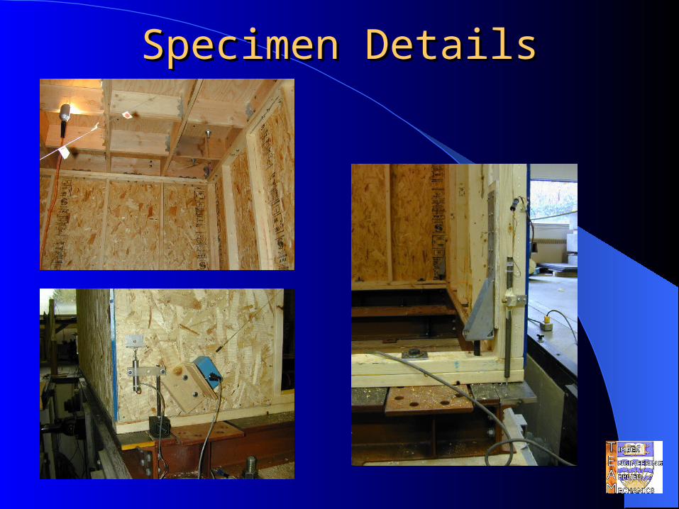
Specimen DetailsSpecimen Details

Model VerificationModel Verification- Static Case 3D- Static Case 3D

3D Model Verification 3D Model Verification Vibration FrequenciesVibration Frequencies
Vibration Mode Experimental Results (Hz)
Model Predictions (Hz)
No.1 (Sway Motion E-W)
2.9 2.8
No.2 (Sway Motion N-S)
5.0 6.1
No.3 (Torsion) 8.8 8.8

Model VerificationModel Verification- Dynamic Case 3D - Dynamic Case 3D
Single Component ShakingSingle Component Shaking
-100
-50
0
50
100
0 5 10 15 20 25 30 35 40 45
Time (sec)
Drift (mm)
Test FEA
-0.50
-0.25
0.00
0.25
0.50
0 5 10 15 20 25 30 35 40 45
Time (sec)
Acce. At Top (g)
Test
FEA

Failed Shake Table SpecimenFailed Shake Table Specimen

Failed Shake Table SpecimenFailed Shake Table Specimen

3D Simplified Model Test 3D Simplified Model Test ObservationsObservations
Significant torsional response Single Component Shaking (~0.4g pga)
– Damage initiated in the narrow wall– Adjacent long wall was also severely damaged– Significant softening after 1st pulse
Two Component Shaking (~0.26g pga)– Two side walls were severely damaged– Significant softening after 1st pulse

Summary on Model DevelopmentSummary on Model Development
Modeling/analytical procedures Program calibrations and verification (Dynamic case) Study of structural parameters and performance
• Experimental procedures Verification of 3D finite element program
Static Dynamic
Reliability based design procedures Response Surfaces Approaches

UBC’s Large Shake TableUBC’s Large Shake Table
20 ft by 25 ft rigid frame
Low friction roller bearings
67 kip, 36 inch actuator

Subsystem Subsystem testingtesting
Simulated weight of 2nd floor

Two Storey House TestTwo Storey House Test