
MECHANICAL SYSTEMS This unit covers the following topics: zMotion zForces zLevers zMoments zLinkages...
38
MECHANICAL SYSTEMS This unit covers the following topics: Motion Forces Levers Moments Linkages Free Body Diagrams Beams Gears Torque and Drive Systems Converting motion
-
Upload
lucas-webb -
Category
Documents
-
view
213 -
download
0
Transcript of MECHANICAL SYSTEMS This unit covers the following topics: zMotion zForces zLevers zMoments zLinkages...

MECHANICAL SYSTEMS
This unit covers the following topics:
Motion Forces Levers Moments Linkages Free Body Diagrams Beams Gears Torque and Drive Systems Converting motion

Introduction
Mechanisms are widely used in industry and society
Many mechanisms will be familiar to you
(Intro continued)
Many industrial processes involve electronic control, mechanisms provide the muscle to do the work
All mechanisms involve:
Some kind of motion Some kind of force Make a job easier to do Need an input to make them work Produce some kind of product
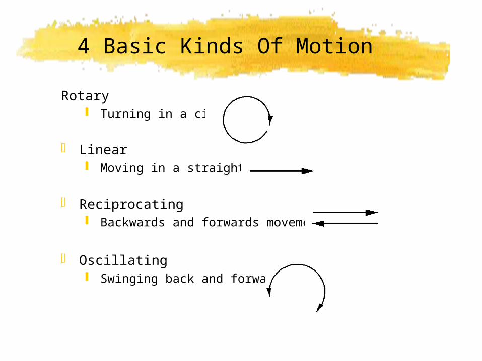
4 Basic Kinds Of Motion
Rotary Turning in a circle
Linear Moving in a straight line
Reciprocating Backwards and forwards movement
Oscillating Swinging back and forwards
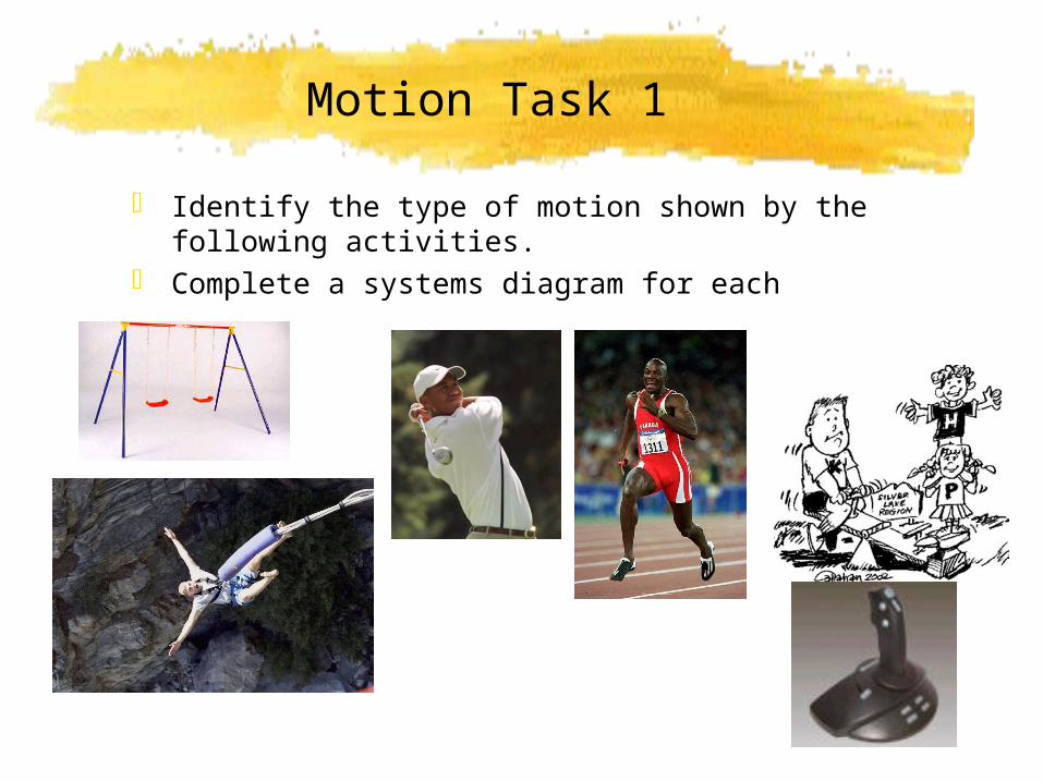
Motion Task 1
Identify the type of motion shown by the following activities.
Complete a systems diagram for each
Motion Task 2
Consider the tools and machines you have used/ seen in CDT
List up to three tools or machines for each basic type of motion
Rotary
Linear
Reciprocating
Oscillating
Forces
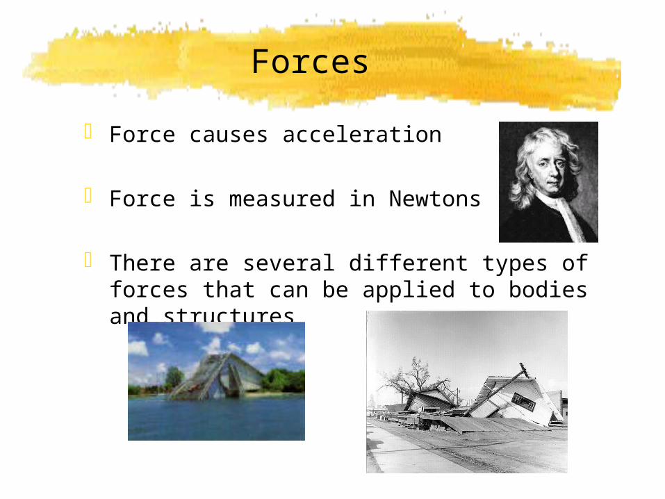
Force causes acceleration
Force is measured in Newtons (N)
There are several different types of forces that can be applied to bodies and structures

Static Forces
Static forces do not usually cause motion
Consider a tall building
The weight of the material it is built from, and thepeople and furniture inside it are static loads
Dynamic Loads
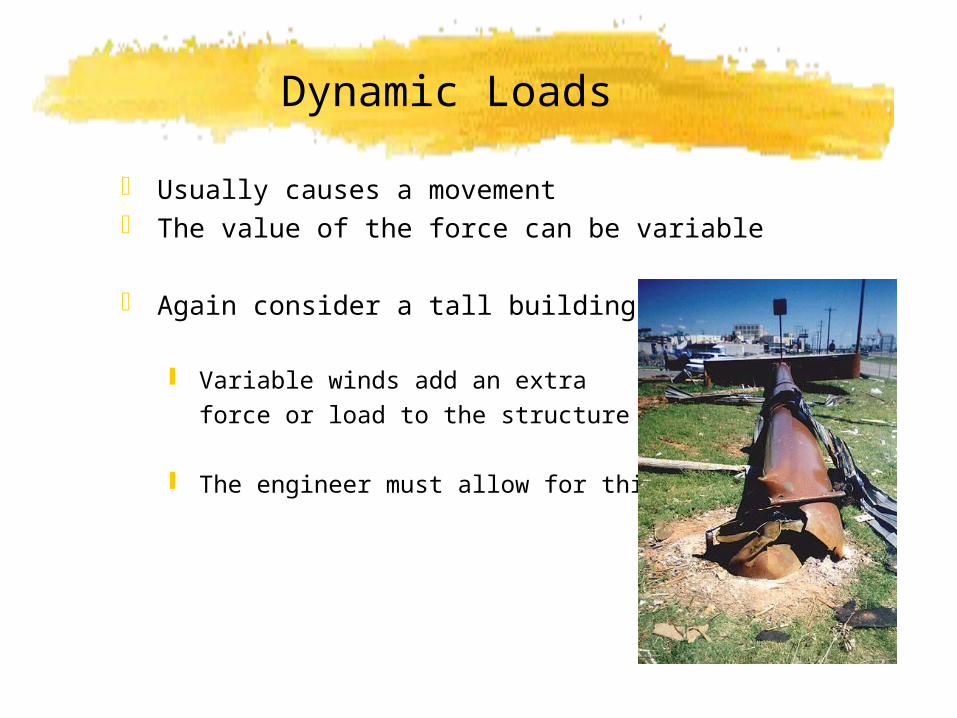
Usually causes a movement The value of the force can be variable
Again consider a tall building
Variable winds add an extra force or load to the structure
The engineer must allow for this
Bending Forces
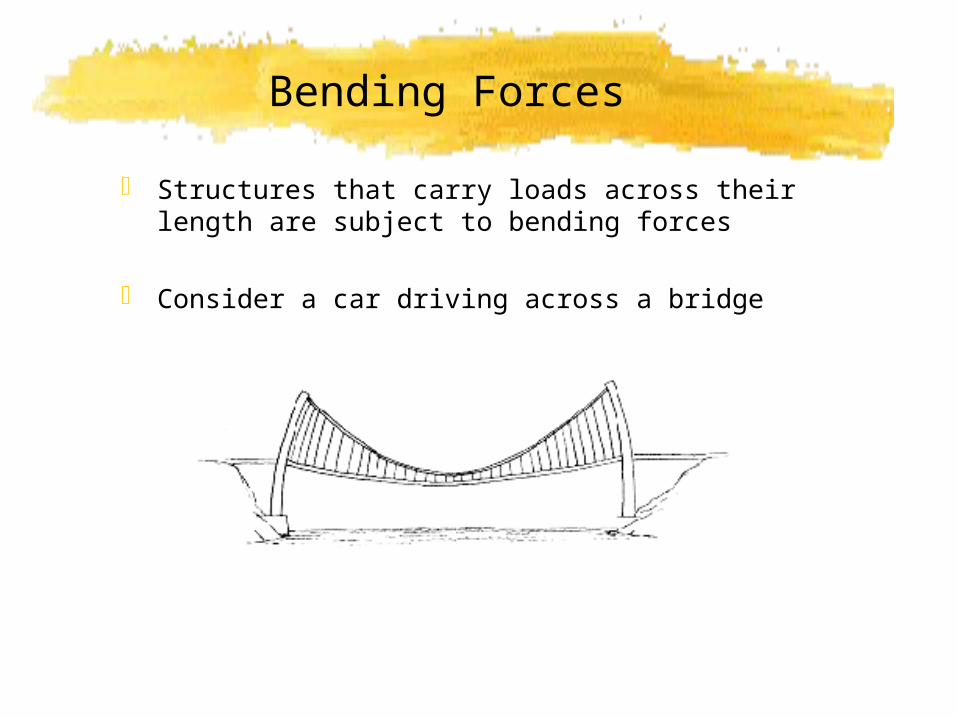
Structures that carry loads across their length are subject to bending forces
Consider a car driving across a bridge
Shear Forces
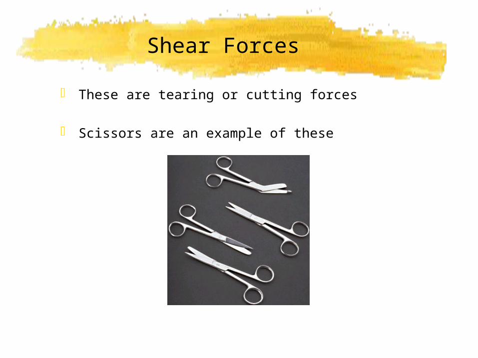
These are tearing or cutting forces
Scissors are an example of these
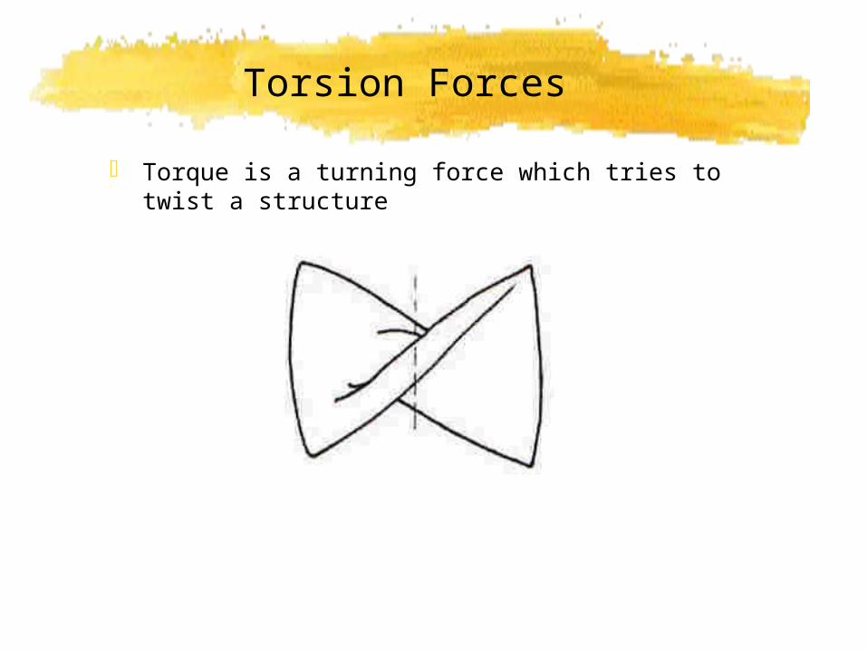
Torsion Forces
Torque is a turning force which tries to twist a structure

Compression Forces
Compression forces try to squash a structure
Consider a column
The weight down is balanced by the reaction from the ground
The forces act to try and shorten the column
C O LU M N
W EIGHT FO R C E W(EXTER NAL FO R C EO N C O LUM N )
W
R
GROUND R EAC TIO N R(EXTER NAL FO R C E O N C O LU M N)
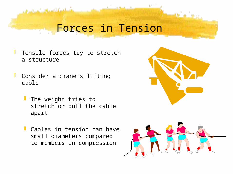
Forces in Tension
Tensile forces try to stretch a structure
Consider a crane’s lifting cable
The weight tries to stretch or pull the cable apart
Cables in tension can have small diameters compared to members in compression

LEVERS In its simplest form, a lever is a stick that is free to pivot or
move back and forth at a certain point.
Levers are probably the most common simple machine because just about anything that has a handle on it has a lever attached.
The point on which the lever moves is called the fulcrum.
By changing the position of the fulcrum, you can gain extra power with less effort.

LEVERS How do you move a heavy person?
If you put the fulcrum in the middle, you won't have a chance. But if you slide the fulcrum closer to the heavy person, it will be easier to lift.
Where's the trade-off?
Well, to get this helping hand, your side of the see-saw is much longer (and higher off the ground), so you have to move it a much greater distance to get the lift

LEVERS
Draw the universal system for a lever
Copy the line diagram of a lever
EFFO RT
LO AD
D ISTANC EM O VED
BY LO AD
D ISTANC EM O VED
BY EFFO RT
LEVER SYSTEM
INPUT FO RCE
INPUT M O TIO N
O UTPUT FO RCE
O UTPUT M O TIO N
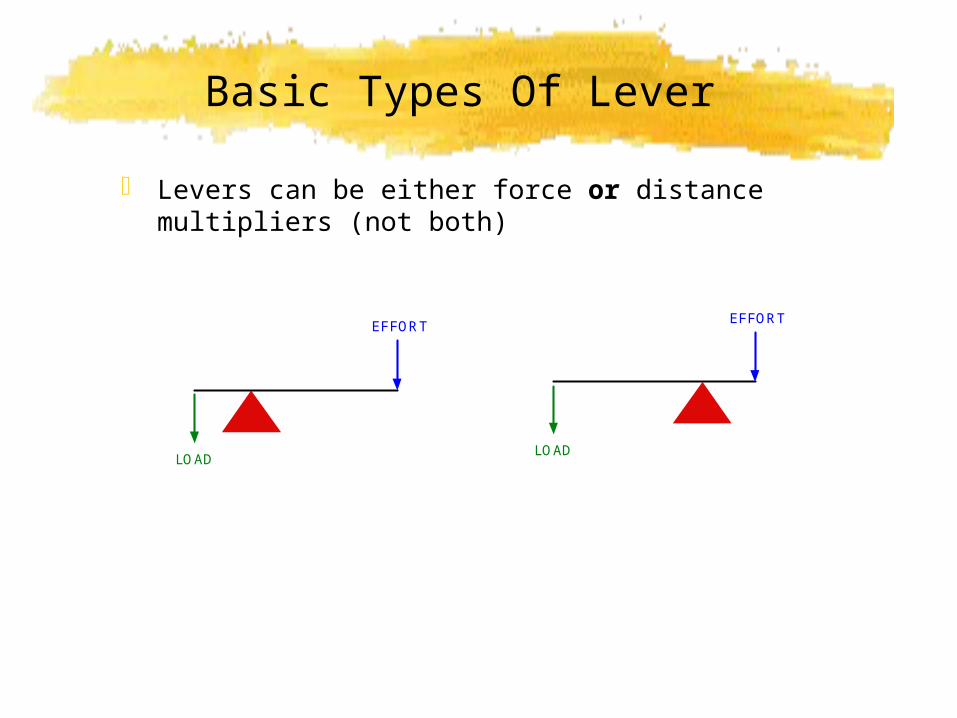
Basic Types Of Lever
Levers can be either force or distance multipliers (not both)
EFFORT
LOAD
EFFORT
LOAD

Force Multiplier Ratio
Consider the lever shown
The LOAD is about 3 times more than the EFFORT
LOAD/EFFORT gives force multiplier ratio
EFFORT = 260 N
LOAD = 750 N
600 mm
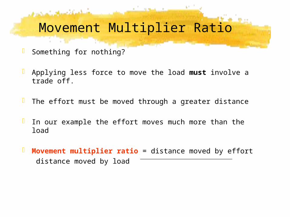
Movement Multiplier Ratio
Something for nothing?
Applying less force to move the load must involve a trade off.
The effort must be moved through a greater distance
In our example the effort moves much more than the load
Movement multiplier ratio = distance moved by effort distance moved by load
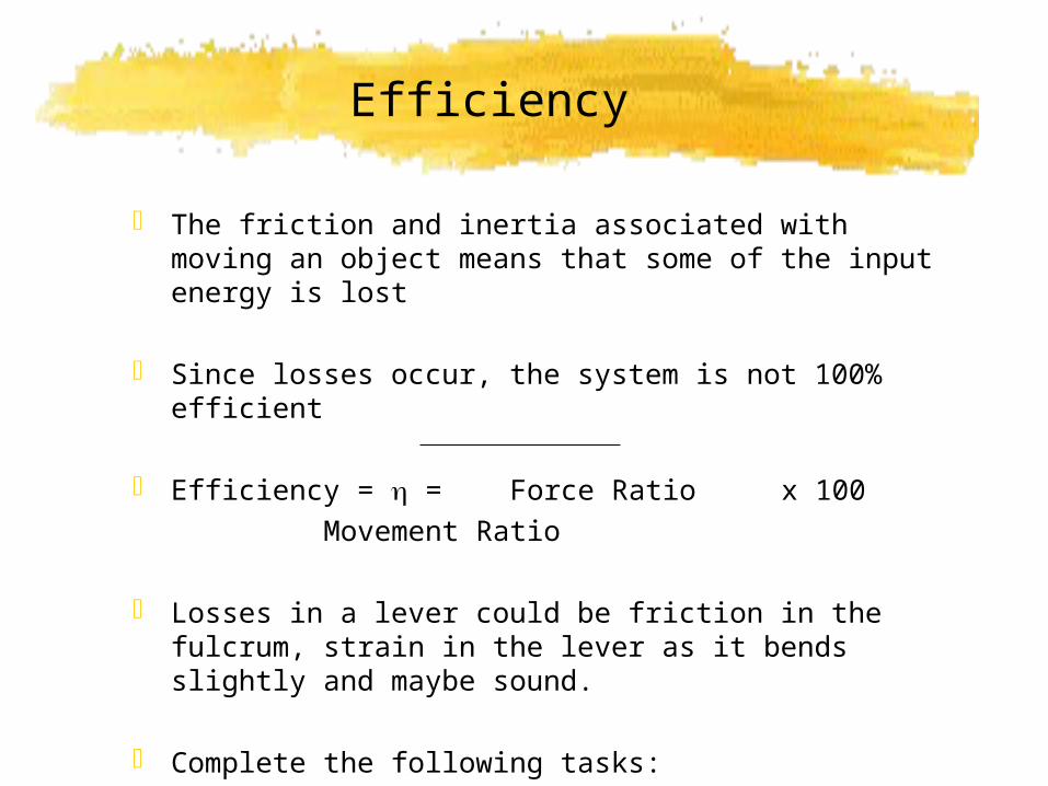
Efficiency
The friction and inertia associated with moving an object means that some of the input energy is lost
Since losses occur, the system is not 100% efficient
Efficiency = = Force Ratio x 100 Movement Ratio
Losses in a lever could be friction in the fulcrum, strain in the lever as it bends slightly and maybe sound.
Complete the following tasks:
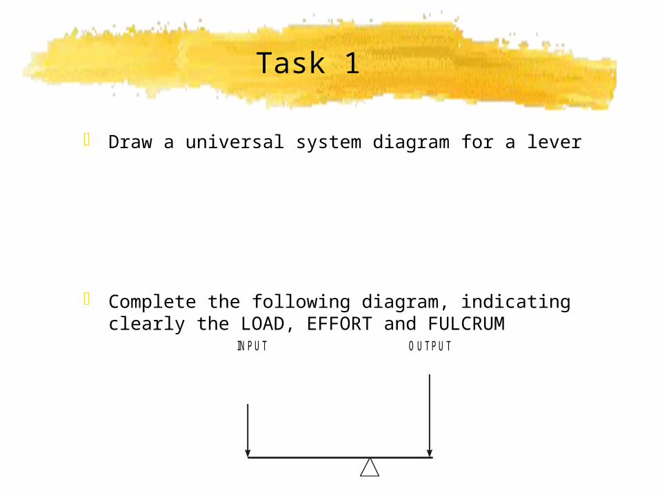
Task 1
Draw a universal system diagram for a lever
Complete the following diagram, indicating clearly the LOAD, EFFORT and FULCRUM
INPUT O U TPU T
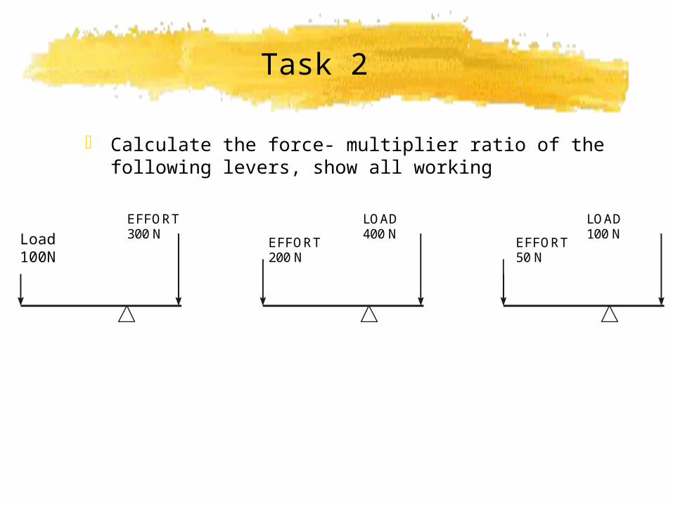
Task 2
Calculate the force- multiplier ratio of the following levers, show all working
EFFORT1OO N
EFFORT300 N
EFFORT200 N
LOAD400 N
EFFORT50 N
LOAD100 NLoad
100N

Task 3
A diagram for a lever system is shown below. Find the force- multiplier of the lever system Calculate the movement- multiplier ratio of the lever Calculate the efficiency of the system Identify possible efficiency losses in the system
EFFORT = 150 N
LOAD = 450 N
650 mm
200 mm
Classes of Levers
Levers can be divided into three distinct types (classes)
Determined by the position of the load, effort and fulcrum.
Class 1
In class 1 levers the effort is on one side of the fulcrum and the load is on the opposite side.
Class 1 levers are the simplest to understand: the longer the crowbar the easier it is to prise open the lid.

CLASS of LEVER Class 2
In class 2 levers the fulcrum is at one end of the lever and the load and the effort are spaced out on the other end of the bar.
The load must be closer to the fulcrum than the effort
A wheelbarrow is a good example of a class 2 lever. The wheel is the fulcrum, the load is in the container area and the effort is applied to the handles. EFFORT
LOAD
FULCRUM
CLASS of LEVER
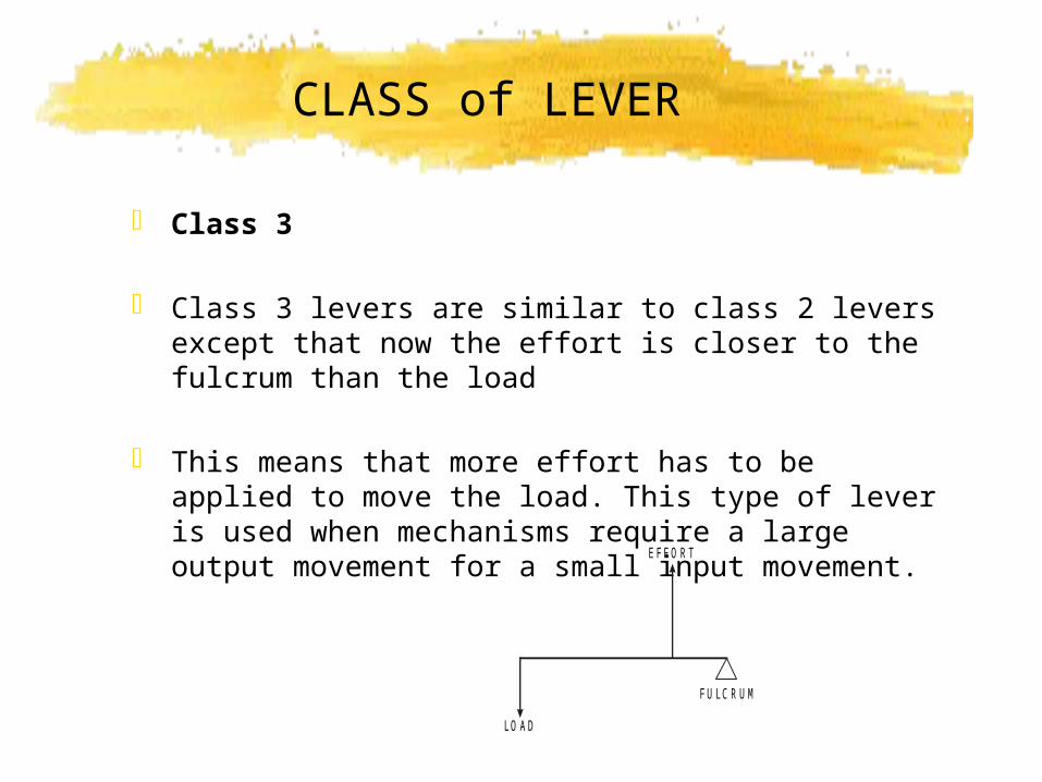
Class 3
Class 3 levers are similar to class 2 levers except that now the effort is closer to the fulcrum than the load
This means that more effort has to be applied to move the load. This type of lever is used when mechanisms require a large output movement for a small input movement.
EFFO RT
LO AD
FU LC R U M
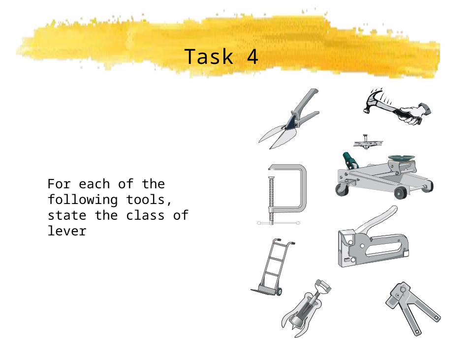
Task 4
For each of the following tools, state the class of lever
M O M E N T S
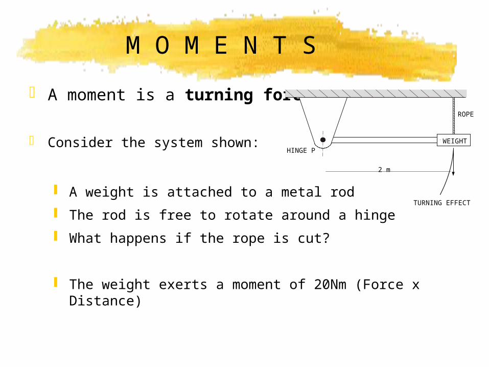
A moment is a turning force
Consider the system shown:
A weight is attached to a metal rod
The rod is free to rotate around a hinge
What happens if the rope is cut?
The weight exerts a moment of 20Nm (Force x Distance)
TURNING EFFECT
2 m
HINGE P
ROPE
WEIGHT
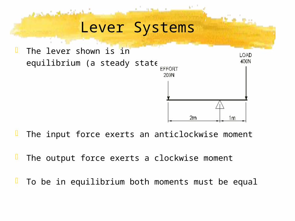
Lever Systems The lever shown is in
equilibrium (a steady state)
The input force exerts an anticlockwise moment
The output force exerts a clockwise moment
To be in equilibrium both moments must be equal
The Principle of Moments
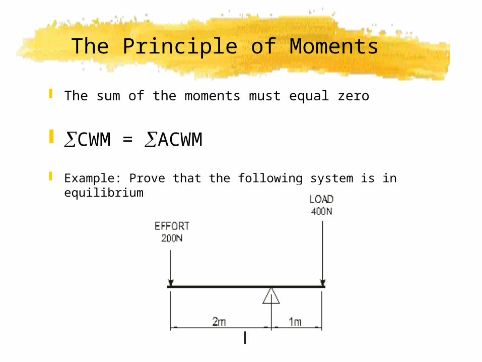
The sum of the moments must equal zero
CWM = ACWM
Example: Prove that the following system is in equilibrium
Solution
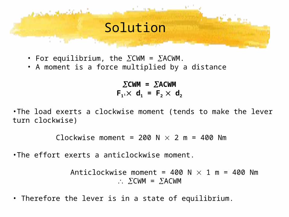
• For equilibrium, the CWM = ACWM. • A moment is a force multiplied by a distance
CWM = ACWMF1¹ d1 = F2 d2
•The load exerts a clockwise moment (tends to make the lever turn clockwise)
Clockwise moment = 200 N 2 m = 400 Nm
•The effort exerts a anticlockwise moment.
Anticlockwise moment = 400 N 1 m = 400 Nm CWM = ACWM
• Therefore the lever is in a state of equilibrium.
Task One
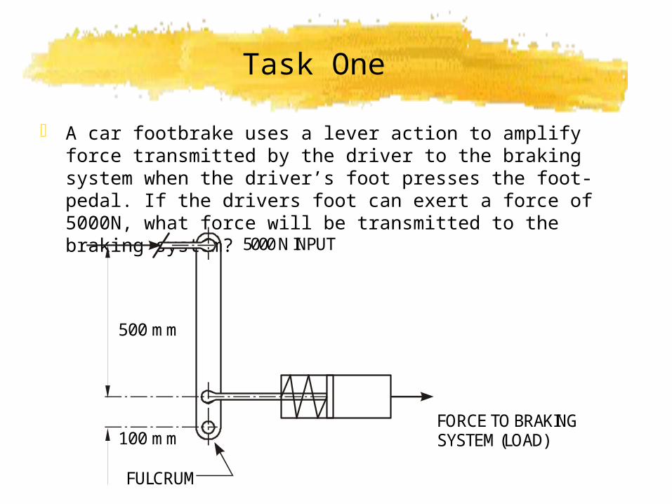
A car footbrake uses a lever action to amplify force transmitted by the driver to the braking system when the driver’s foot presses the foot-pedal. If the drivers foot can exert a force of 5000N, what force will be transmitted to the braking system?
100 mm
500 mm
5000 N INPUT
FULCRUM
FORCE TO BRAKINGSYSTEM (LOAD)
Solution
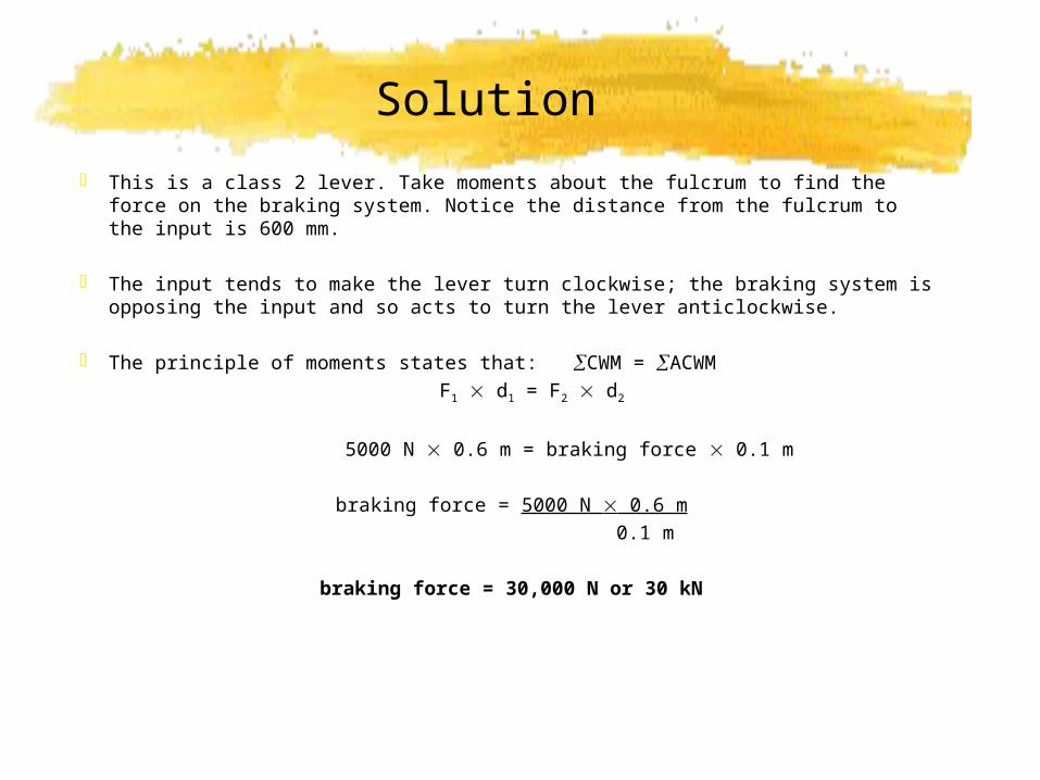
This is a class 2 lever. Take moments about the fulcrum to find the force on the braking system. Notice the distance from the fulcrum to the input is 600 mm.
The input tends to make the lever turn clockwise; the braking system is opposing the input and so acts to turn the lever anticlockwise.
The principle of moments states that: CWM = ACWM F1 d1 = F2 d2
5000 N 0.6 m = braking force 0.1 m
braking force = 5000 N 0.6 m 0.1 m
braking force = 30,000 N or 30 kN
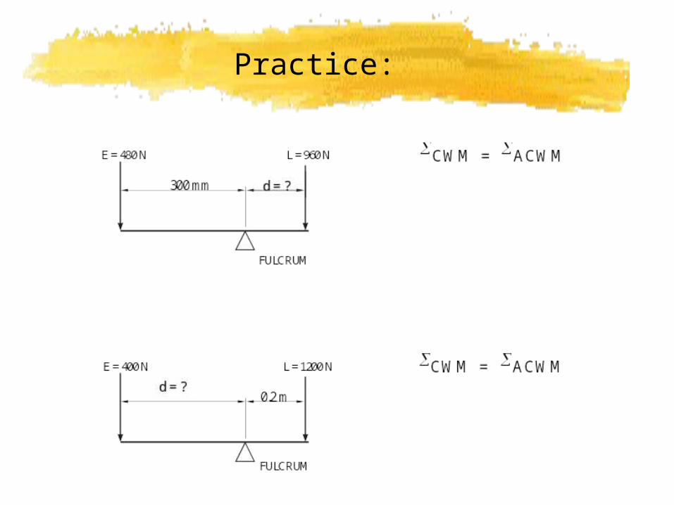
Practice:
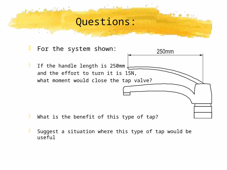
Questions:
For the system shown:
If the handle length is 250mm and the effort to turn it is 15N, what moment would close the tap valve?
What is the benefit of this type of tap?
Suggest a situation where this type of tap would be useful
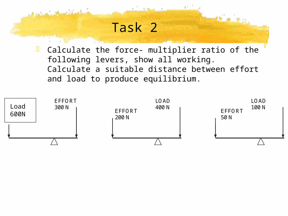
Task 2
Calculate the force- multiplier ratio of the following levers, show all working. Calculate a suitable distance between effort and load to produce equilibrium.
EFFORT1OO N
EFFORT300 N
EFFORT200 N
LOAD400 N
EFFORT50 N
LOAD100 NLoad
600N
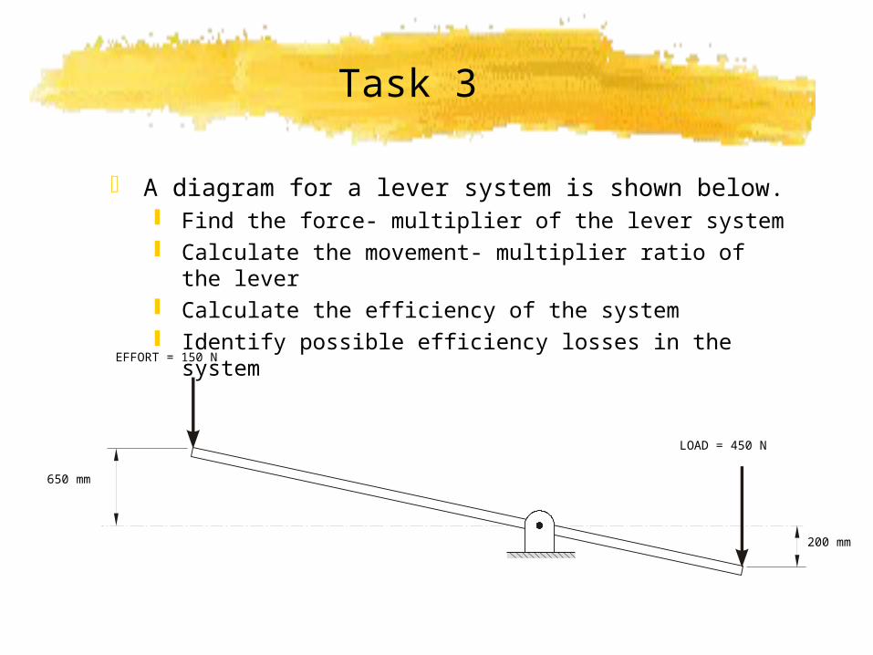
Task 3
A diagram for a lever system is shown below. Find the force- multiplier of the lever system Calculate the movement- multiplier ratio of the lever Calculate the efficiency of the system Identify possible efficiency losses in the system
EFFORT = 150 N
LOAD = 450 N
650 mm
200 mm


