Mechanical Sensors Chapter 6. Force sensors A class of sensors Includes a fairly large number of...
137
Mechanical Sensors Chapter 6
-
Upload
noel-bradford -
Category
Documents
-
view
219 -
download
0
Transcript of Mechanical Sensors Chapter 6. Force sensors A class of sensors Includes a fairly large number of...

Mechanical SensorsMechanical Sensors
Chapter 6Chapter 6
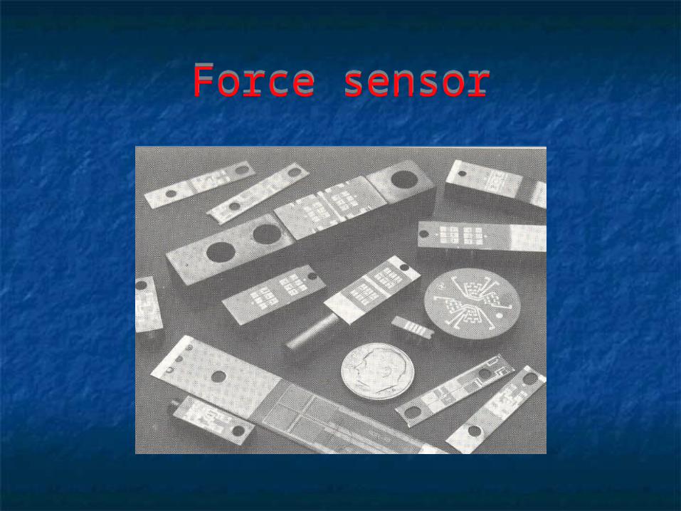
Force sensorsForce sensors
A class of sensors Includes a fairly large number of different sensors Based on many principles Will discuss four types of general sensors
force sensors accelerometers pressure sensors gyroscopes
cover most principles involved in sensing of mechanical quantities - directly and indirectly.
A class of sensors Includes a fairly large number of different sensors Based on many principles Will discuss four types of general sensors
force sensors accelerometers pressure sensors gyroscopes
cover most principles involved in sensing of mechanical quantities - directly and indirectly.

Force sensorsForce sensors
Some of these sensors are used for applications which initially do not seem to relate to mechanical quantities. Example: measure temperature through expansion of
gases in a volume (pneumatic temperature sensor discussed in chapter 3).
Some mechanical sensors do not involve motion or force. Example: the fiber optic gyroscope and will be
discussed below
Force sensors - Strain GaugesForce sensors - Strain Gauges
Strain gauge - The main tool in sensing force. Strain gauges, measure strain Strain can be related to stress, force, torque and
a host of other stimuli including displacement, acceleration or position.
At the heart of all strain gauges is the change in resistance of materials due to change in their length due to strain.

Force sensors - Strain GaugesForce sensors - Strain Gauges
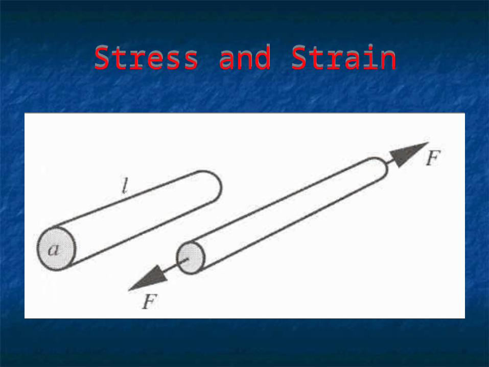
Definition of strain: consider a length of metallic wire L, of conductivity and cross-sectional area A.
The resistance of the wire is:
Definition of strain: consider a length of metallic wire L, of conductivity and cross-sectional area A.
The resistance of the wire is:
R =
L
A
Taking the log on both sides:
log R = log
1
+ logL
a
= − log + logL
A
Force sensors - Strain GaugesForce sensors - Strain Gauges
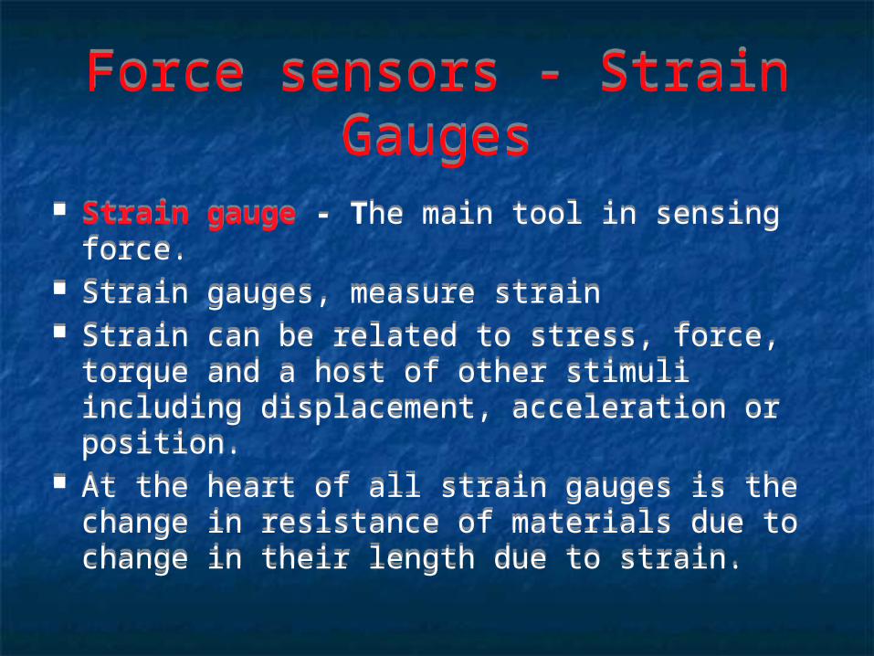
Taking the differential on both sides:Taking the differential on both sides:
Change in resistance is due to two terms:Due to change in conductivityDue to the deformation of the conductor.
For small deformations (linear deformation), both terms on the right hand side are linear functions of strain, . Bundling both effects together (that is, the change in conductivity and deformation) we can write:
dR
R
= − d
+
d ( L / A )
L / A
Force sensors - Strain GaugesForce sensors - Strain Gauges
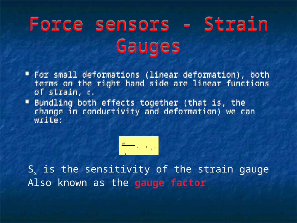
For small deformations (linear deformation), both terms on the right hand side are linear functions of strain, .
Bundling both effects together (that is, the change in conductivity and deformation) we can write:
For small deformations (linear deformation), both terms on the right hand side are linear functions of strain, .
Bundling both effects together (that is, the change in conductivity and deformation) we can write:
dR
R
= Ss
Ss is the sensitivity of the strain gaugeAlso known as the gauge factor
Strain GaugeStrain Gauge
For any given strain gauge the gauge factor is a constant
Ranges between 2 to 6 for most metallic strain gauges
From 40-200 for semiconductor strain gauges. The strain gauge relation gives a simple linear
relation between the change in resistance of the sensor and the strain applied to it.
For any given strain gauge the gauge factor is a constant
Ranges between 2 to 6 for most metallic strain gauges
From 40-200 for semiconductor strain gauges. The strain gauge relation gives a simple linear
relation between the change in resistance of the sensor and the strain applied to it.
Stress and StrainStress and Strain
Strain and StressStrain and Stress
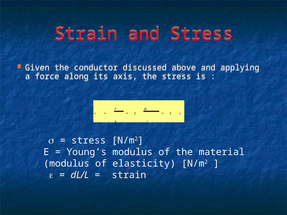
Given the conductor discussed above and applying a force along its axis, the stress is :
Given the conductor discussed above and applying a force along its axis, the stress is :
=
F
A
= E
dL
L
= E ε
= stress [N/m2]E = Young’s modulus of the material (modulus of elasticity) [N/m2 ] = dL/L = strain
Strain and StressStrain and Stress
Strain is a normalized linear deformation of the material
Stress is a measure of elasticity of the material.
Strain is a normalized linear deformation of the material
Stress is a measure of elasticity of the material.
Strain gaugesStrain gauges
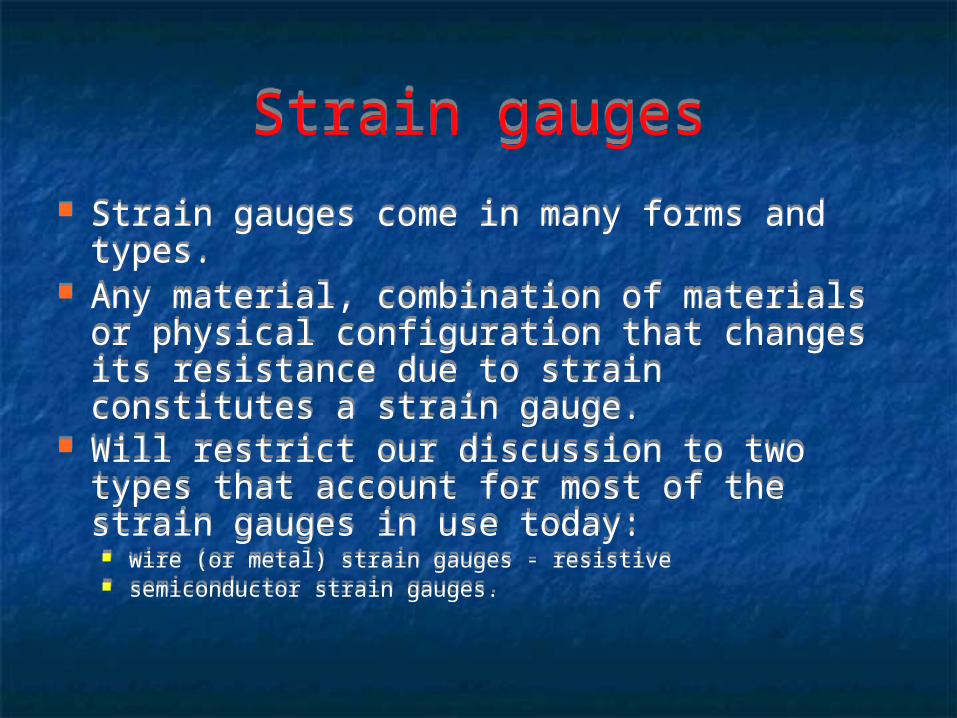
Strain gauges come in many forms and types. Any material, combination of materials or
physical configuration that changes its resistance due to strain constitutes a strain gauge.
Will restrict our discussion to two types that account for most of the strain gauges in use today: wire (or metal) strain gauges - resistive semiconductor strain gauges.

metallic strain gaugemetallic strain gauge
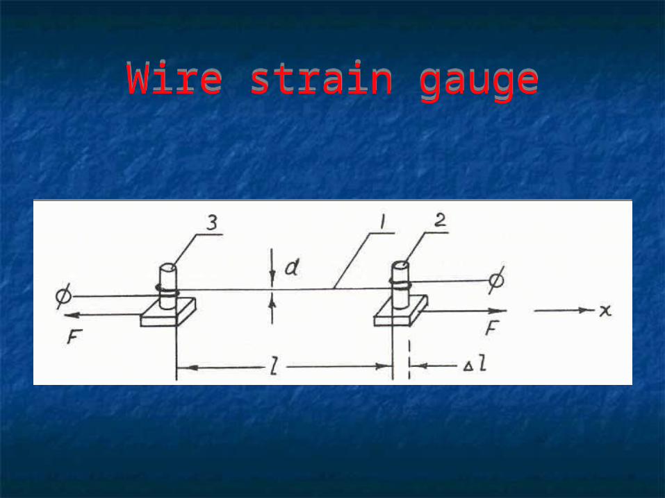
In its simplest form: A length of wire, held between two posts When a force is applied to them, will deform the
wire causing a change in the wire’s resistance. This method was used in the past and is valid It is not very practical (construction, attachment
to system, change in resistance is very small). Sometimes, multiple lengths of wire were used.
Wire strain gaugeWire strain gauge
Metallic strain gauge common form
Metallic strain gauge common form
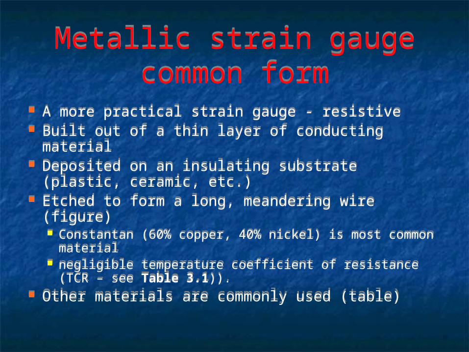
A more practical strain gauge - resistive Built out of a thin layer of conducting material Deposited on an insulating substrate (plastic,
ceramic, etc.) Etched to form a long, meandering wire (figure)
Constantan (60% copper, 40% nickel) is most common material
negligible temperature coefficient of resistance (TCR – see Table 3.1)).
Other materials are commonly used (table)

The resistive strain gaugeThe resistive strain gauge

Materials for resistive strain gauges
Materials for resistive strain gauges
Table 6.1. Materials for resistive strain gauges and their properties.
Material Gagefactor
Resistivity[Ωmm2/m]
Thermalcoeff.ofexpansion[10−6/°K]
Expansioncoeff.[10−6/°K]
Maximumtemperatrure[°C]
Constantan (Cu60Ni40) 2.0 0.48 5 12.5 400Nichrome (Ni80Cr20) 2.0 1.3 100 18 1000Manganine(Cu84Mn12Ni4)
2.2 0.43 10 17
Nickel -12 0.11 6000 12Chromel (Ni65Fe25Cr10) 2.5 0.9 300 15 800Platinum 5.1 0.1 2450 8.9 1300Elinvar(Fe55Ni36Cr8Mn0.5)
3.8 0.84 300 9
Platinum-Iridium(Pt80Ir20)
6.0 0.36 1700 8.9 1300
Platinum Rhodium(Pt90Rh10)
4.8 0.23 1500 8.9
Bismuth 22 1.19 300 13.4
Metallic strain gauge common form
Metallic strain gauge common form
Strain gauges may also be used to measure multiple axis strains by simply using more than one gauge or by producing them in standard configurations.
Some of these are shown next.
Strain gauges may also be used to measure multiple axis strains by simply using more than one gauge or by producing them in standard configurations.
Some of these are shown next.
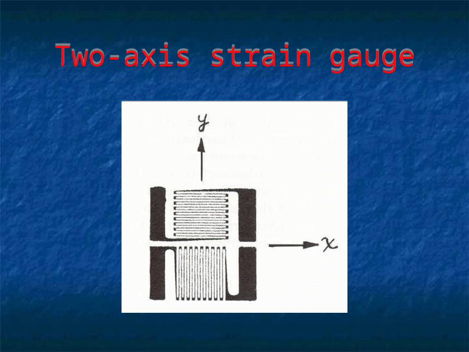
Two-axis strain gaugeTwo-axis strain gauge
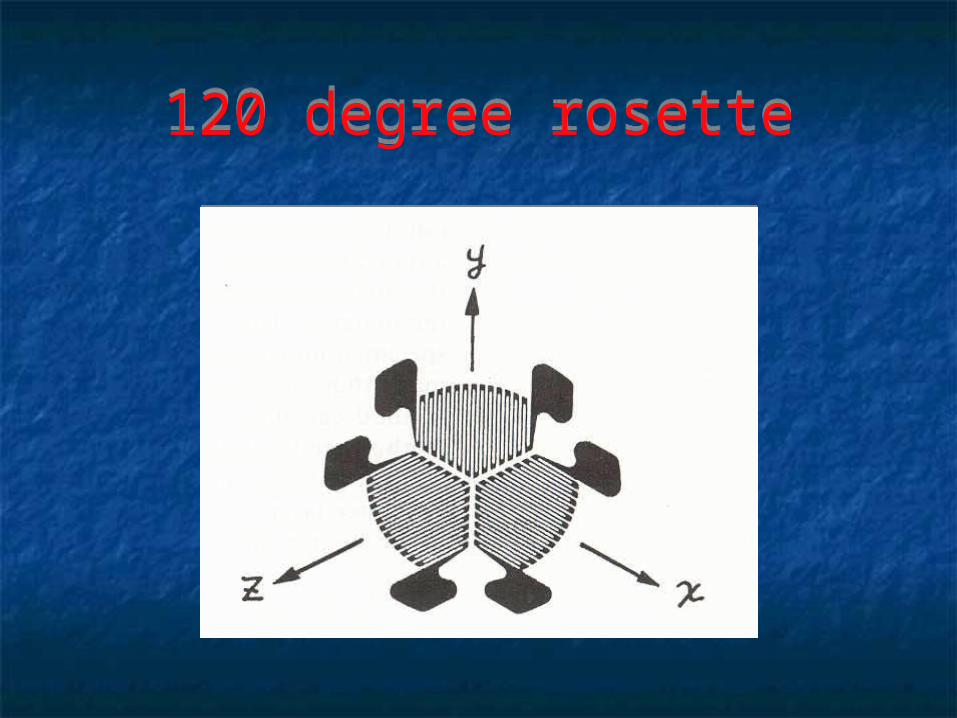
120 degree rosette120 degree rosette

45 degree rosette45 degree rosette

45 degree stacked rosette45 degree stacked rosette

membrane rosettemembrane rosette

Semiconductor strain gaugesSemiconductor strain gauges
Operate like resistive strain gauges Construction and properties are different. The gauge factor for semiconductors is much
higher than for metals. The change in conductivity due to strain is much
larger than in metals. Are typically smaller than metal types Often more sensitive to temperature variations
(require temperature compensation).
Semiconductor strain gaugesSemiconductor strain gauges
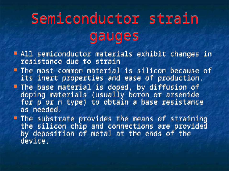
All semiconductor materials exhibit changes in resistance due to strain
The most common material is silicon because of its inert properties and ease of production.
The base material is doped, by diffusion of doping materials (usually boron or arsenide for p or n type) to obtain a base resistance as needed.
The substrate provides the means of straining the silicon chip and connections are provided by deposition of metal at the ends of the device.

Semiconductor strain gaugesSemiconductor strain gauges
Construction of a semiconductor strain gauge:
Construction of a semiconductor strain gauge:

Semiconductor strain gaugesSemiconductor strain gauges
Other types of semiconductor strain gauges:
Other types of semiconductor strain gauges:

Semiconductor strain gaugesSemiconductor strain gauges
One of the important differences between conductor and semiconductor strain gauges is that semiconductor strain gauges are essentially nonlinear devices with typically a quadratic transfer function:
One of the important differences between conductor and semiconductor strain gauges is that semiconductor strain gauges are essentially nonlinear devices with typically a quadratic transfer function:
dR
R
= S1
+ S1
2
Also: PTC or NTC operation

PTC and NTC operationPTC and NTC operation
Strain gauges - applicationsStrain gauges - applications
Strain gauge must be made to react to a force. The strain gauge is attached to the member in which strain is
sensed, usually by bonding. Cannot be re-used! Special bonding agents exist for different applications and types of
materials Usually supplied by the manufacturers of strain gauges or
specialized producers. Strain gauges are often used for bending strain,
twisting (torsional and shear strain) and longitudinal tensioning/deformation (axial strain) of structures (engine shafts, bridge loading, truck weighing and many many others)
Strain gauges - propertiesStrain gauges - properties
The properties of strain gauges vary by application Most metal gauges have a nominal resistance
between 100 and 1000Ω, (lower and higher resistances are available)
Gauge factor between 2-5 Dimensions from less than 3x3 mm to lengths in
excess of 150 mm (almost any size may be fabricated if necessary).
Rosettes (multiple axis strain gauges) are available with 45, 90 and 120 axes as well as diaphragm and other specialized configurations.
Strain gauges - propertiesStrain gauges - properties
Typical sensitivities are 5mΩΩ Deformation is of the order of 2-3m/m. Much higher strains can be measured with specialized
gauges. Semiconductor strain gauges usually smaller than most resistive strain gauges can be made with higher resistances. their use is limited to low temperatures can be much less expensive than metal strain gauges. often part of another device

Strain gauges - errorsStrain gauges - errors
Strain gauges are subject to a variety of errors. Due to temperatures - resistance, especially in
semiconductors, is affected by temperature in the same way as by strain.
In metal gauges, this is usually small (materials with low temperature coefficients of resistance).
In semiconductors, temperature compensation is sometimes provided on board or a separate sensor may be used for this purpose.

Strain gauges - errorsStrain gauges - errors
A third source of error is due to the strain itself, which, over time, tends, to permanently deform the gauge. can be eliminated by periodic re-calibration can be reduced by ensuring that the
maximum deformation allowed is small and below the recommended for the device.
A third source of error is due to the strain itself, which, over time, tends, to permanently deform the gauge. can be eliminated by periodic re-calibration can be reduced by ensuring that the
maximum deformation allowed is small and below the recommended for the device.
Strain gauges - errorsStrain gauges - errors
Additional errors Due the bonding process Thinning of materials due to cycling. Most strain gauges are rated for:
given number of cycles (i.e. 106 or 107 cycles), maximum strain (3% is typical for conducting strain
gauges, 1% for semiconductor strain gauges) temperature characteristics specified for use with a
particular material (aluminum, stainless steel, carbon steel) for optimal performance when bonded
Typical accuracies are of the order of 0.2-0.5%.

Typical resistive strain gaugesTypical resistive strain gauges
Other Strain GaugesOther Strain Gauges
Other strain gauges - for specialized applications.
Optical fiber strain gauges. The change in length of the fiber due to strain
changes the phase of the light through the fiber. Measuring the light phase, either directly or in an
interferrometric method can produce readings of minute strain that cannot be obtained in other strain gauges.
The device and the electronics necessary is far more complicated than standard gauges.

Other Strain GaugesOther Strain Gauges
There are also liquid strain gauges which rely in the resistance of an electrolytic liquid in a flexible container which can be deformed.
Another type of strain gauge that is used on a limited basis is the plastic strain gauge.
These are made as ribbons or threads based on graphite or carbon in a resin as a substrate and used in a way similar to other strain gauges.
Very high gauge factors (up to about 300), they are otherwise difficult to use and inaccurate as well as unstable mechanically, severely limiting their practical use.
Force and tactile sensorsForce and tactile sensors
Forces can be measured in many ways The simplest - use a strain gauge Calibrate the output in units of force.
Other methods include measuring acceleration of a mass (F=ma), measuring the displacement of a spring under action of
force (x=kF, k is the spring constant), measuring the pressure produced by force and some
variations of these basic methods. None of these is a direct measure of force most are more complicated than use of a strain gauge.
Force and tactile sensorsForce and tactile sensors
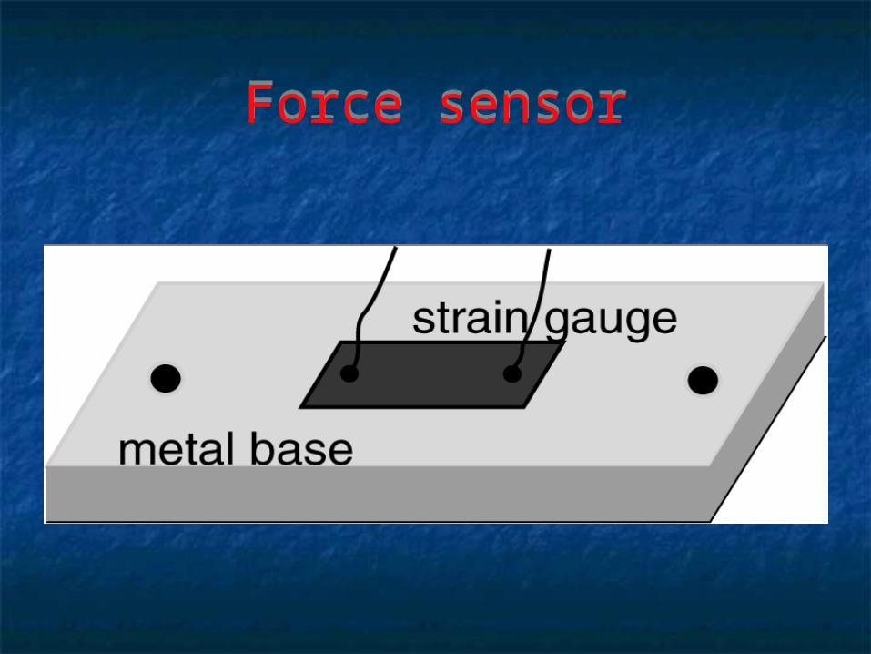
The basic method is shown in Figure 6.9. One measures the tensile force by measuring the strain
in the strain gauge. The sensor is usually provided with attachment holes may also be used in compressive mode by pre-stressing the
strain gauge. This type of sensor is often used to measure forces in
locations such as machine tools, engine mounts and the like.
Often it is called a load cell, especially when large forces are measured.
Force sensorForce sensor
Force sensorForce sensor

Load cellsLoad cells
Tactile sensorsTactile sensors
Tactile sensors are force sensors but: Definition of “tactile” action is broader, the
sensors are also more diverse. One view is that tactile action as simply sensing
the presence of force. Then: A simple switch is a tactile sensor This approach is commonly used in keyboards Membrane or resistive pads are used The force is applied against the membrane or a
silicon rubber layer.
Tactile sensorsTactile sensors
In many tactile sensing applications it is often important to sense a force distribution over a specified area (such as the “hand” of a robot).
Either an array of force sensors or A distributed sensor may be used. These are usually made from piezoelectric films
which respond with an electrical signal in response to deformation (passive sensors).
An example is shown in Figure 6.11.
A tactile sensorA tactile sensor

Tactile sensorsTactile sensors
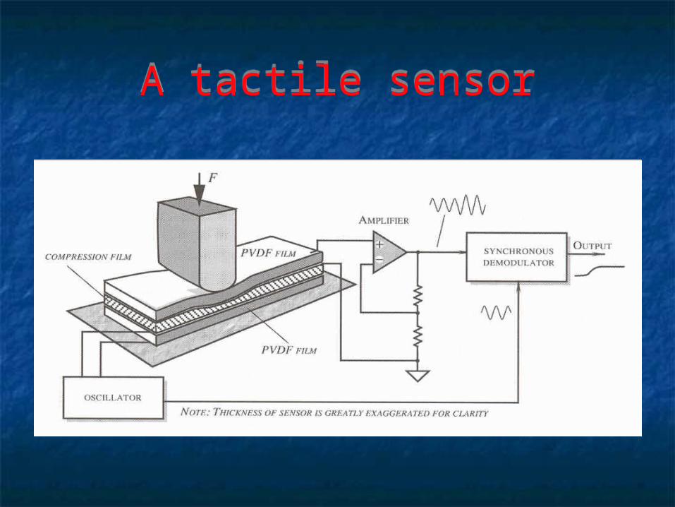
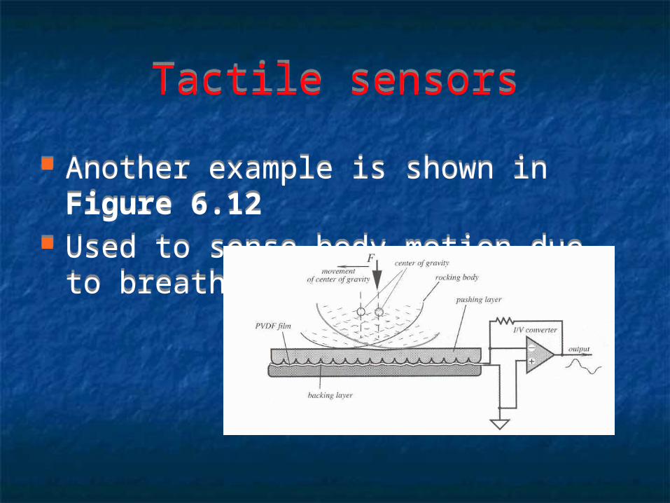
Operation: The polyvinylidene fluoride (PVDF) film is
sensitive to deformation. The lower film is driven with an ac signal It contracts and expands mechanically and
periodically. When the upper film is deformed, its signal
changes from normal and the amplitude and or phase of the output signal is now a measure of deformation (force).
Tactile sensorsTactile sensors
Another example is shown in Figure 6.12 Used to sense body motion due to
breathing.
Another example is shown in Figure 6.12 Used to sense body motion due to
breathing.

Tactile sensorsTactile sensors
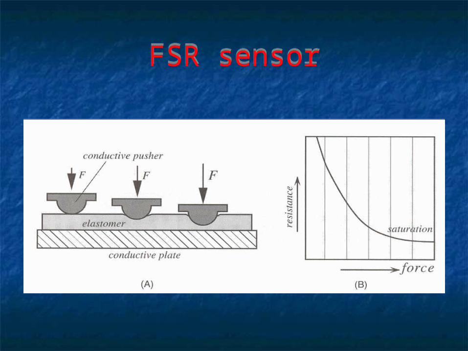
The simplest tactile sensors are made of conductive polymers or elastomers or with semiconductive polymers
Called piezoresistive sensors or force sensitive resistive (FSR) sensors.
In these devices, the resistance of the material is pressure dependent and is shown schematically in Figure 6.13.
The simplest tactile sensors are made of conductive polymers or elastomers or with semiconductive polymers
Called piezoresistive sensors or force sensitive resistive (FSR) sensors.
In these devices, the resistance of the material is pressure dependent and is shown schematically in Figure 6.13.
FSR sensorFSR sensor
Tactile sensorsTactile sensors
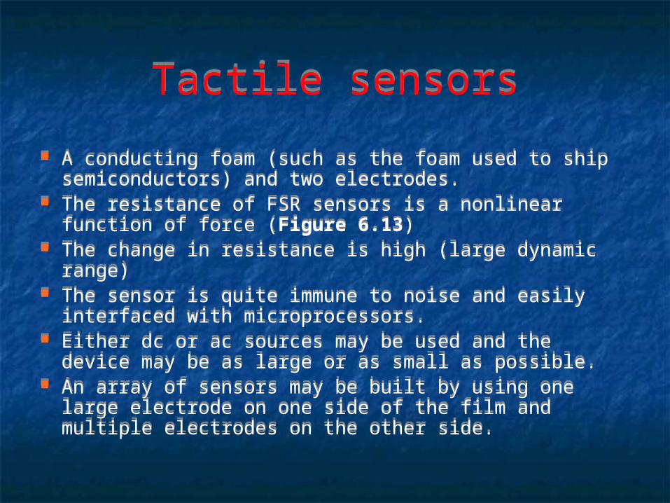
A conducting foam (such as the foam used to ship semiconductors) and two electrodes.
The resistance of FSR sensors is a nonlinear function of force (Figure 6.13)
The change in resistance is high (large dynamic range) The sensor is quite immune to noise and easily interfaced
with microprocessors. Either dc or ac sources may be used and the device may
be as large or as small as possible. An array of sensors may be built by using one large
electrode on one side of the film and multiple electrodes on the other side.
AccelerometersAccelerometers
By virtue of Newton’s second law (F = ma) a sensor may be made to sense acceleration by simply measuring the force on a mass.
At rest, acceleration is zero and the force on the mass is zero.
At any acceleration a, the force on the mass is directly proportional given a fixed mass.
This force may be sensed in any method of sensing force but, again, the strain gauge will be representative of direct force measurement.
AccelerometersAccelerometers
Other methods of sensing acceleration. Magnetic methods and electrostatic (capacitive) methods
are quite commonly used. The distance between the mass and a fixed surface, which
depends on acceleration can be made into a capacitor. Capacitance increases (or decreases) with acceleration.
A magnetic sensor can be used by measuring the field of a magnetic mass. The higher the acceleration, the closer (or farther) the magnet from a fixed surface and hence the larger or lower the magnetic field.
The methods used in chapter 5 to sense position or proximity can now be used to sense acceleration.
Accelerometers - principlesAccelerometers - principles
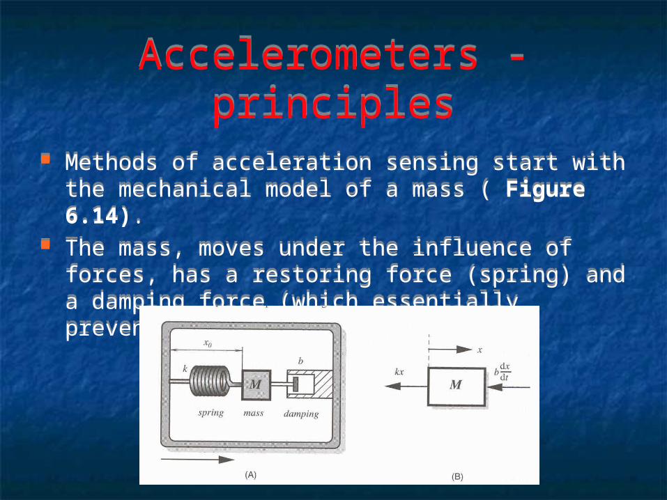
Methods of acceleration sensing start with the mechanical model of a mass ( Figure 6.14).
The mass, moves under the influence of forces, has a restoring force (spring) and a damping force (which essentially prevents it from oscillating).
Methods of acceleration sensing start with the mechanical model of a mass ( Figure 6.14).
The mass, moves under the influence of forces, has a restoring force (spring) and a damping force (which essentially prevents it from oscillating).

Accelerometers - principlesAccelerometers - principles
Under these conditions, and assuming the mass can only move in one direction (along the horizontal axis), Newton’s second law may be written as:
Under these conditions, and assuming the mass can only move in one direction (along the horizontal axis), Newton’s second law may be written as:
ma = − kx − bdx
dt
Assumes that the mass has moved a distance x under the influence of acceleration, k is the restoring (spring) constant and b is the damping coefficient. Given the mass m and the constants k and b, a measurement of x gives an indication of the acceleration a.
Accelerometers - principlesAccelerometers - principles
Therefore, for a useful acceleration sensor (often called accelerometer) it is sufficient to provide a component which can move relative to the sensor’s housing and a means of sensing this movement.
A displacement sensor (position, proximity, etc.) can be used to provide an appropriate output proportional to acceleration.
Accelerometers - CapacitiveAccelerometers - Capacitive
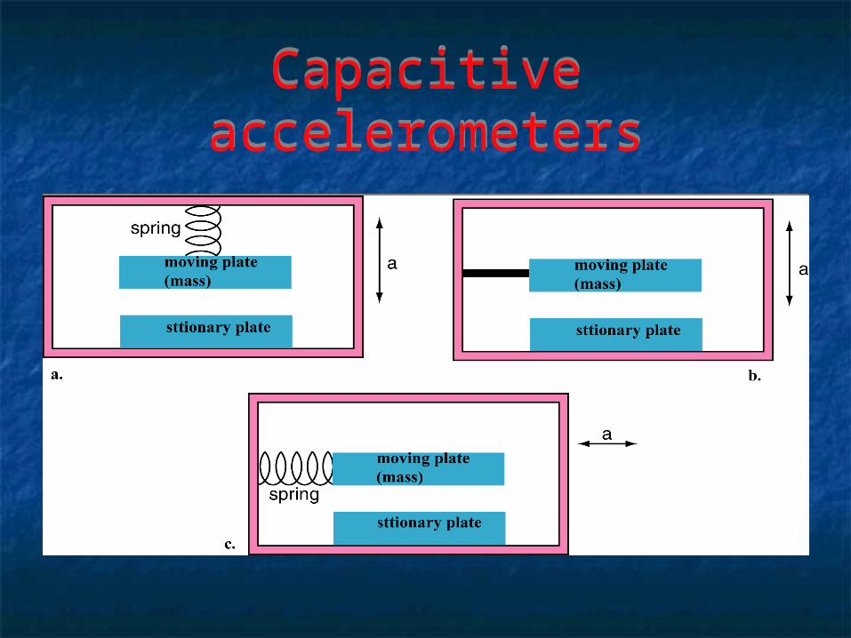
One plate of a small capacitor is fixed and connected physically to the body of the sensor.
A second plate serves as the inertial mass of the sensor is free to move and connected to a restoring spring.
Three basic configurations are shown in Figure 6.15.
The restoring force is provided by springs (Figure 6.15a,c) or by a cantilever’s fixed end (Figure 6.15b).
Capacitive accelerometersCapacitive accelerometers
Accelerometers - CapacitiveAccelerometers - Capacitive
In Figure 6.15a and 6.15b, the distance between the plates changes with acceleration.
In Figure 6.15c, the effective area of the plates changes while the distance between the plates stays constant.
In either case, acceleration either increases the capacitance or decreases it, depending on the direction of motion.
In a practical accelerator, the plates must be prevented from touching by stoppers
Some kind of damping mechanism must be added to prevent the springs or the beam from oscillating

Capacitive accelerometers - practical considerations
Capacitive accelerometers - practical considerations
A more practical device: A more practical device:
Capacitive accelerometers - practical considerations
Capacitive accelerometers - practical considerations
Cantilever beam End of travel stops Capacitance proportional to vertical acceleration
Changes in capacitance are very small Indirect methods such as using the capacitor in an LC
oscillator are used. The frequency of oscillation is a direct measure of
acceleration. Can be produced as semiconductor devices by
etching both the mass, fixed plate and springs directly into silicon.

Capacitive accelerometers - practical considerations
Capacitive accelerometers - practical considerations
Second structure: a bridge structure: The mass moves between two plates and forms an upper
and lower capacitor. A differential mode is obtained since at rest the two
capacitors are the same.
Second structure: a bridge structure: The mass moves between two plates and forms an upper
and lower capacitor. A differential mode is obtained since at rest the two
capacitors are the same.

Strain gauge accelerometersStrain gauge accelerometers
The mass is suspended on a cantilever beam Strain gauge senses the bending of the beam
The mass is suspended on a cantilever beam Strain gauge senses the bending of the beam
Variable inductance accelerometers
Variable inductance accelerometers
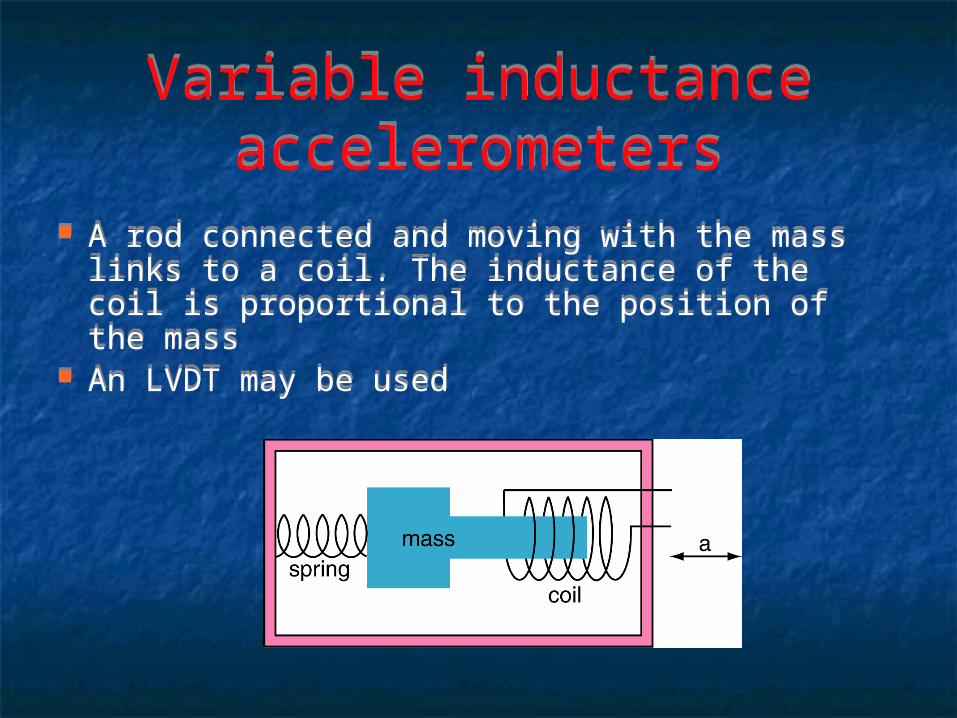
A rod connected and moving with the mass links to a coil. The inductance of the coil is proportional to the position of the mass
An LVDT may be used
A rod connected and moving with the mass links to a coil. The inductance of the coil is proportional to the position of the mass
An LVDT may be used
Hall element magnetic accelerometers
Hall element magnetic accelerometers
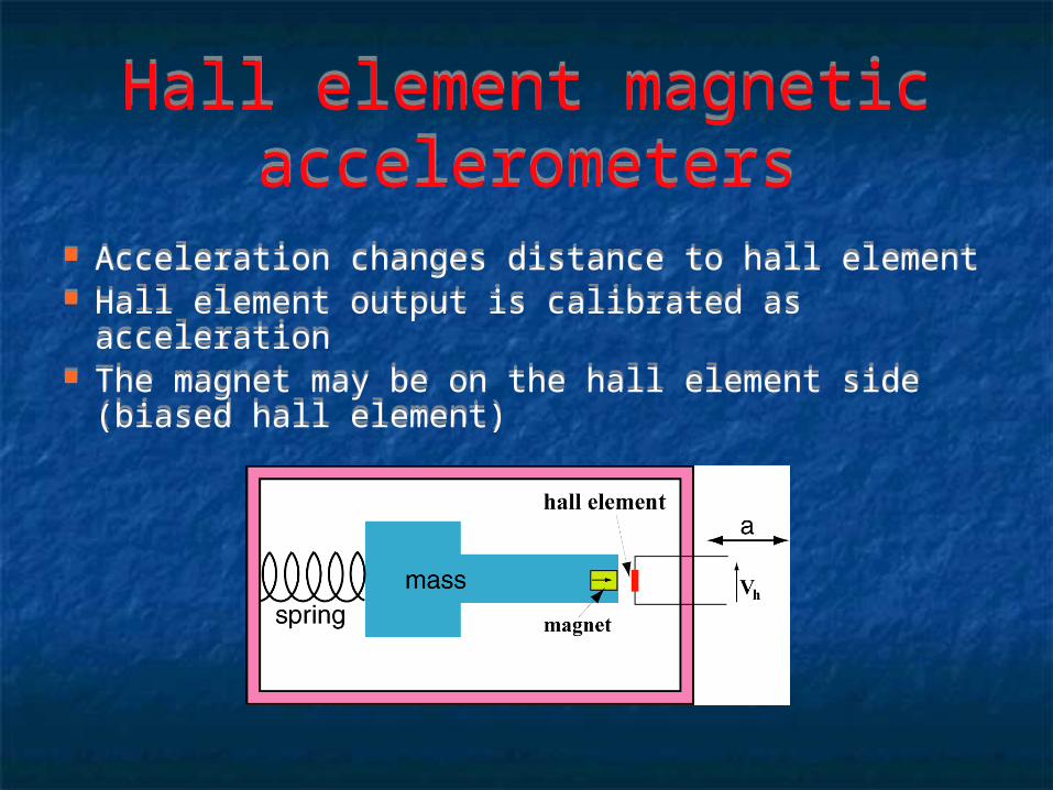
Acceleration changes distance to hall element Hall element output is calibrated as acceleration The magnet may be on the hall element side
(biased hall element)
Acceleration changes distance to hall element Hall element output is calibrated as acceleration The magnet may be on the hall element side
(biased hall element)
Other types of accelerometersOther types of accelerometers
Many other types of accelerometers All employ a moving mass in one form or another. Example: the heated gas accelerometer Gas in cavity is heated to an equilibrium temp. Two (or more) thermocouples are provided
equidistant from the heater. Under rest conditions, the two thermocouples are
at the same temperature. Their reading (one thermocouples is the sense thermocouple, the second the reference thermocouple) is zero.
Other types of accelerometersOther types of accelerometers
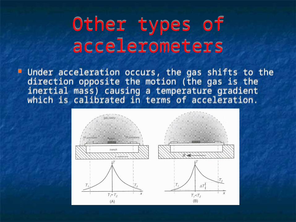
Under acceleration occurs, the gas shifts to the direction opposite the motion (the gas is the inertial mass) causing a temperature gradient which is calibrated in terms of acceleration.
Under acceleration occurs, the gas shifts to the direction opposite the motion (the gas is the inertial mass) causing a temperature gradient which is calibrated in terms of acceleration.

Other types of accelerometersOther types of accelerometers
Other accelerometers use optical means Example: activating a variable shutter by
means of the moving mass Optical fiber accelerometers use an optical
fiber position sensor, Vibrating reeds whose vibration rate
changes with acceleration Many more.
Other accelerometers use optical means Example: activating a variable shutter by
means of the moving mass Optical fiber accelerometers use an optical
fiber position sensor, Vibrating reeds whose vibration rate
changes with acceleration Many more.
Accelerometers - notesAccelerometers - notes
Multiple axis accelerometers can be built by essentially using single axis accelerometers with axes perpendicular to each other.
These can be fabricated as two or three axes accelerometer or two or three single axis accelerometers may be attached appropriately.
Proper damping must be provided to avoid oscillations of the mass while still keeping reasonable response times.
The uses of accelerometers are vast and include air bag deploying sensors, door unlocking, weapons guidance systems, vibration and shock measurement, satellites, intrusion alarms (by detecting motion), and control and other similar applications.

Accelerometers - notesAccelerometers - notes
Sensitivity: from a few g and up Noise and errors: vibrations, temperature
variations, deterioration of the return spring
Sensitivity: from a few g and up Noise and errors: vibrations, temperature
variations, deterioration of the return spring

Velocity sensingVelocity sensing
Velocity sensing is more complicated than acceleration sensing.
One can always measure something proportional to velocity. For example: We may infer the velocity of a car from the rotation of
the wheels Or the transmission shaft ( a common method of
velocity measurement in cars) Or count the number of rotation of a shaft per unit
time in an electric motor.

Velocity sensingVelocity sensing
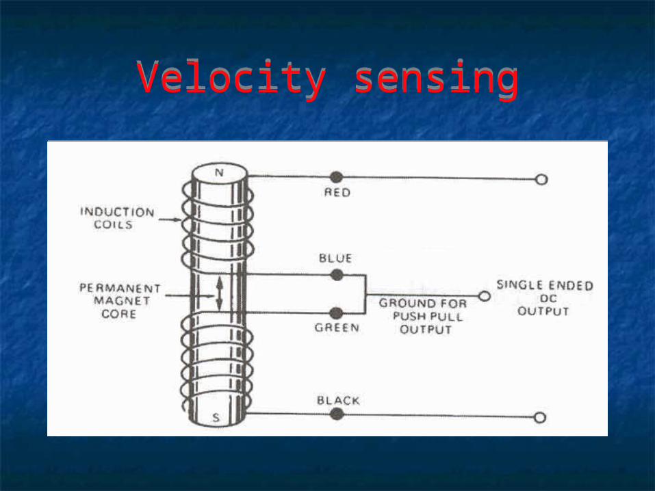
A free-standing sensor that measures velocity directly is much more difficult to produce.
One approach that may be used is the induction of emf in a coil due to a magnet.
This requires that the coil be stationary If the velocity is constant (no acceleration) the magnet
cannot move relative to the coil. For changing velocity (when acceleration is not zero),
the principle in Figure 6.21 may be useful.
Velocity sensingVelocity sensing
Velocity sensingVelocity sensing
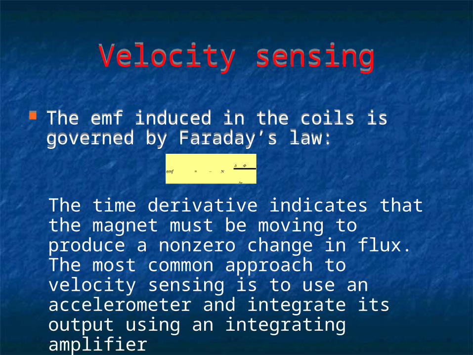
The emf induced in the coils is governed by Faraday’s law:
The emf induced in the coils is governed by Faraday’s law:
The time derivative indicates that the magnet must be moving to produce a nonzero change in flux.The most common approach to velocity sensing is to use an accelerometer and integrate its output using an integrating amplifier
emf = − Nd Φ
dt

Velocity sensingVelocity sensing
constant velocity cannot be sensed (zero acceleration)
Relative velocity of objects is easily measured
We shall see fluid velocity sensors Also doppler effect sensors, time of flight
devices - etc,
constant velocity cannot be sensed (zero acceleration)
Relative velocity of objects is easily measured
We shall see fluid velocity sensors Also doppler effect sensors, time of flight
devices - etc,

Pressure sensors - introductionPressure sensors - introduction
Sensing of pressure is only second in importance to sensing of strain in mechanical systems
These sensors are used either in their own right, (to measure pressure), or to sense secondary quantities such as force, power, temperature and the like.
One of the reasons for their prominence is that in sensing gases and fluids, force is not an option – only pressure can be measured and related to properties of these substances.

Pressure sensors - introductionPressure sensors - introduction
Another reason for their widespread use and of exposure of most people to them is their use in cars, atmospheric weather prediction, heating and other consumer oriented devices.
The “barometer” hanging on many a wall and the use of atmospheric pressure as indication of weather conditions has helped popularize the concept of pressure and pressure sensing
Pressure sensors - UnitsPressure sensors - Units
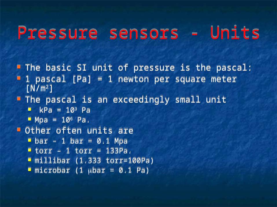
The basic SI unit of pressure is the pascal: 1 pascal [Pa] = 1 newton per square meter [N/m2] The pascal is an exceedingly small unit
kPa = 103 Pa Mpa = 106 Pa.
Other often units are bar – 1 bar = 0.1 Mpa torr – 1 torr = 133Pa. millibar (1.333 torr=100Pa) microbar (1 bar = 0.1 Pa)
The basic SI unit of pressure is the pascal: 1 pascal [Pa] = 1 newton per square meter [N/m2] The pascal is an exceedingly small unit
kPa = 103 Pa Mpa = 106 Pa.
Other often units are bar – 1 bar = 0.1 Mpa torr – 1 torr = 133Pa. millibar (1.333 torr=100Pa) microbar (1 bar = 0.1 Pa)
Pressure sensors - UnitsPressure sensors - Units
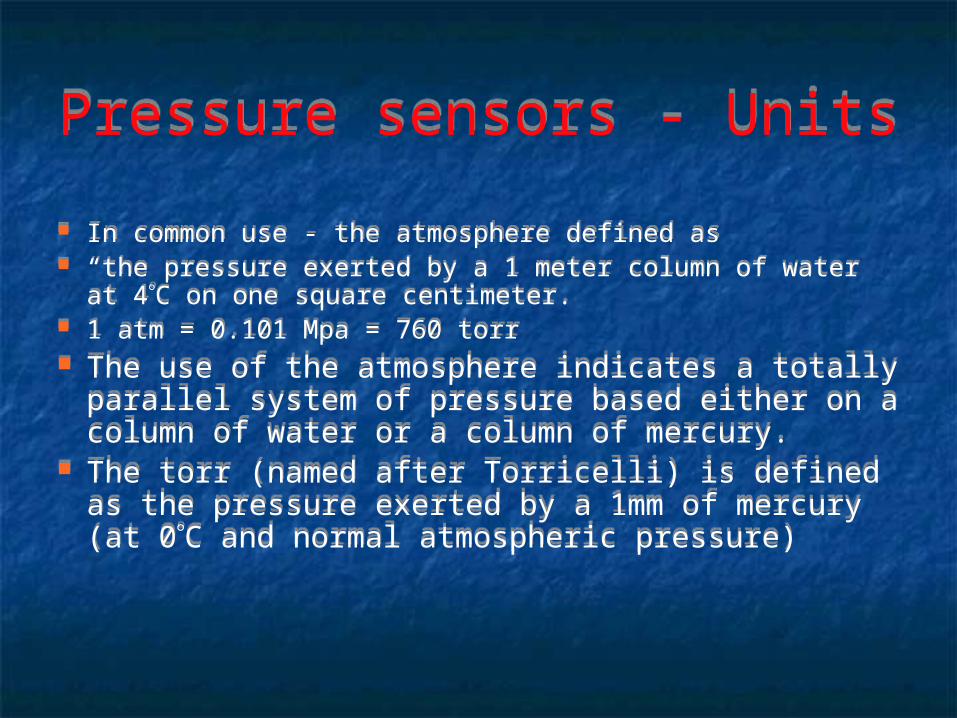
In common use - the atmosphere defined as “the pressure exerted by a 1 meter column of water at 4C
on one square centimeter. 1 atm = 0.101 Mpa = 760 torr The use of the atmosphere indicates a totally
parallel system of pressure based either on a column of water or a column of mercury.
The torr (named after Torricelli) is defined as the pressure exerted by a 1mm of mercury (at 0C and normal atmospheric pressure)
Pressure sensors - UnitsPressure sensors - Units
In the US the common (non-metric) unit of pressure is the psi (pounds per square inch):
1 psi = 6.89 kPa = 0.0703 atm. Vacuum is often used, sometimes as a separate
quantity. Vacuum means lack of pressure, Understood as indicating pressure below ambient. One talks about so many psi of vacuum This simply refers to so many psi below ambient
pressure.

System of units for pressursSystem of units for pressurs
Pressure sensingPressure sensing
Pressure is force per unit area Sensing it follows the same principle as the
sensing of force – Measuring the displacement of an appropriate
member of the sensor in response to pressure. The range of methods is quite large and includes
thermal, optical as well as magnetic and electrical principles.
Earliest sensors were purely mechanical
Mechanical pressure sensorsMechanical pressure sensors
Mechanical pressure sensors. Direct transduction from pressure to mechanical
displacement These devices are actuators that react to pressure Are as common today as ever. Some mechanical devices have been combined with
other sensors to provide electrical output Others are still being used in their original form. The most common of these is the Bourdon tube.
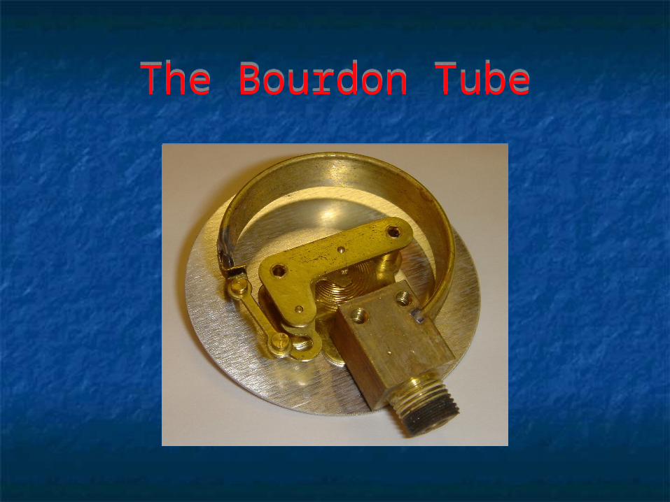
The Bourdon TubeThe Bourdon Tube
Mechanical pressure sensorsMechanical pressure sensors
Has been used for over a century in pressure gauges The dial indicator is connected directly to the tube. Still the most common pressure gauge used today
does not need additional components simple inexpensive.
Typically used for gases but it can also be used for sensing fluid pressure.
Tire gauges, fuel gauges, etc.
Bellows and diaphragmsBellows and diaphragms
Principle: expansion of a diaphragm or a bellows under the influence of pressure.
The motion produces may be used to directly drive an indicator or
May be sensed by a displacement sensor (LVDT, magnetic, capacitive etc.)
A simple diaphragm pressure sensor used in wall barometers is shown in Figure 6.24.

Diaphragm pressure sensorDiaphragm pressure sensor
Bellows and diaphragmsBellows and diaphragms
One side is held fixed (in this case by the small screw which also serves to adjust, or calibrate it)
The other moves in response to pressure. The device is hermetically sealed at a given pressure Any pressure below the internal pressure will force the
diaphragm to expand (like a baloon) Any higher pressure will force it to contract. Very simple and trivially inexpensive, but:
Possibility of leakage Dependence on temperature.

Bellows and diaphragmsBellows and diaphragms
A bellows (Figure 6.25) is a similar device
Can be used for direct reading or to activate another sensor.
The bellows, in various forms is also being used as an actuator.
One of its common uses is in “vacuum motors” used in vehicles to activate valves and to move slats and doors, particularly in heating and air conditioning systems.
Membranes and platesMembranes and plates
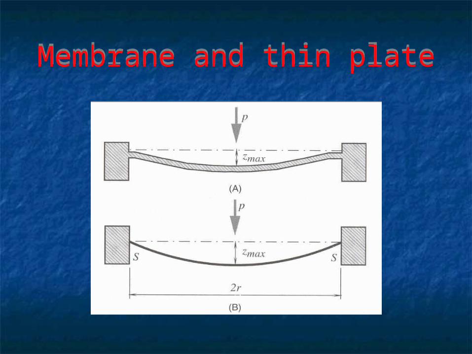
The most common devices used for pressure sensing are the thin plate and the diaphragm or membrane.
Membrane: a thin plate with negligible thickness Thin plate: a thick membrane Their behavior and response to pressure is
different. In relation to Figure 6.26, the deflection of the center of a membrane (maximum deflection) which is under radial tension S and the stress in the diaphragm are given as:
Membrane and thin plateMembrane and thin plate
Membranes and thin platesMembranes and thin plates
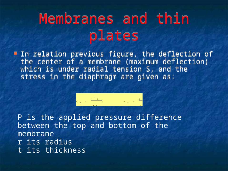
In relation previous figure, the deflection of the center of a membrane (maximum deflection) which is under radial tension S, and the stress in the diaphragm are given as:
In relation previous figure, the deflection of the center of a membrane (maximum deflection) which is under radial tension S, and the stress in the diaphragm are given as:
dm
= r
2
P
4 S
, m
= S
t
P is the applied pressure difference between the top and bottom of the membraner its radius t its thickness
Membranes and thin platesMembranes and thin plates
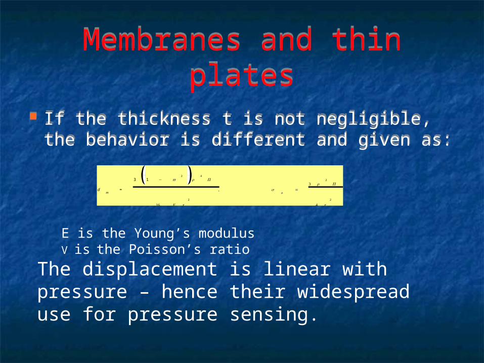
If the thickness t is not negligible, the behavior is different and given as:
If the thickness t is not negligible, the behavior is different and given as:
E is the Young’s modulus V is the Poisson’s ratio
The displacement is linear with pressure – hence their widespread use for pressure sensing.
dm
=
3 1 − v2
r4
P
16 E t2
, m
= 3 r
2P
4 t2

Pressure sensorsPressure sensors
Pressure sensors come in four basic types : Absolute pressure sensors (PSIA): pressure sensed
relative to absolute vacuum. Differential pressure sensors (PSID): the difference
between two pressures on two ports of the sensor is sensed.
Gage pressure sensors (PSIG): the pressure relative to ambient pressure is sensed. (Most common)
Sealed gage pressure sensor (PSIS): the pressure relative to a sealed pressure chamber (usually 1 atm at sea level or 14.7 psi) is sensed.
Piezoresistive pressure sensors
Piezoresistive pressure sensors
Piezoresistor is a semiconductor strain gauge Most modern pressure sensors use it rather than
the conductor type strain gauge. Resistive (metal) strain gauges are used only at
higher temperature or for specialized applications
May be fabricated of silicon simplifies construction allows on board temperature compensation,
amplifiers and conditioning circuitry.

Piezoresistive pressure sensorsPiezoresistive pressure sensors
Basic structure: two gauges are parallel to one dimension of
the diaphragm The two gauges can be in other directions
Basic structure: two gauges are parallel to one dimension of
the diaphragm The two gauges can be in other directions
Piezoresistive pressure sensorsPiezoresistive pressure sensors
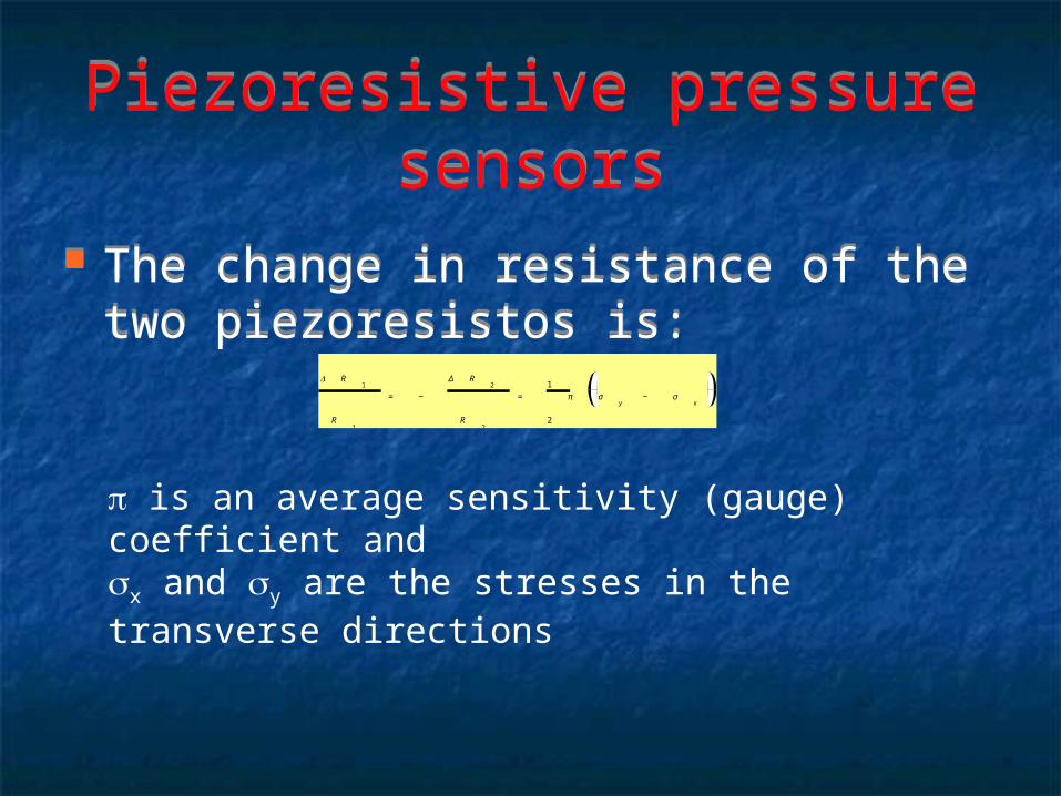
The change in resistance of the two piezoresistos is:
The change in resistance of the two piezoresistos is:
Δ R1
R1
= −
Δ R2
R2
=
1
2
π σy
− σx
is an average sensitivity (gauge) coefficient andx and y are the stresses in the transverse directions

Piezoresistive pressure sensorsPiezoresistive pressure sensors
Piezoresistors and the diaphragm are fabricated of silicon.
A vent is provided, making this a gage sensor. If the cavity under the diaphragm is
hermetically closed and the pressure in it is P0, the sensor becomes a sealed gage pressure sensor sensing the pressure P-P0.
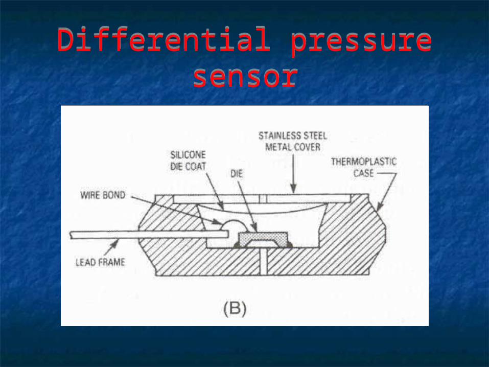
A differential sensor is produced by placing the diaphragm between two chambers, each vented through a port (figure).
Piezoresistors and the diaphragm are fabricated of silicon.
A vent is provided, making this a gage sensor. If the cavity under the diaphragm is
hermetically closed and the pressure in it is P0, the sensor becomes a sealed gage pressure sensor sensing the pressure P-P0.
A differential sensor is produced by placing the diaphragm between two chambers, each vented through a port (figure).
Differential pressure sensorDifferential pressure sensor
Piezoresistive pressure sensorsPiezoresistive pressure sensors
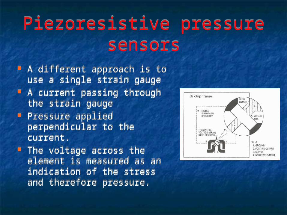
A different approach is to use a single strain gauge
A current passing through the strain gauge
Pressure applied perpendicular to the current.
The voltage across the element is measured as an indication of the stress and therefore pressure.
A different approach is to use a single strain gauge
A current passing through the strain gauge
Pressure applied perpendicular to the current.
The voltage across the element is measured as an indication of the stress and therefore pressure.

ConstructionConstruction
Many variations Body of sensor is particularly important Silicon, steel, stainless steel and titanium
are most commonly used Ports are made with various fittings The contact material is specified (gas,
fluid, corrosivity, etc.)
Many variations Body of sensor is particularly important Silicon, steel, stainless steel and titanium
are most commonly used Ports are made with various fittings The contact material is specified (gas,
fluid, corrosivity, etc.)
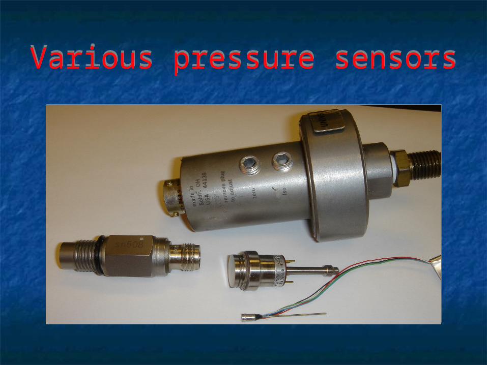
Various pressure sensorsVarious pressure sensors

Miniature pressure sensorsMiniature pressure sensors
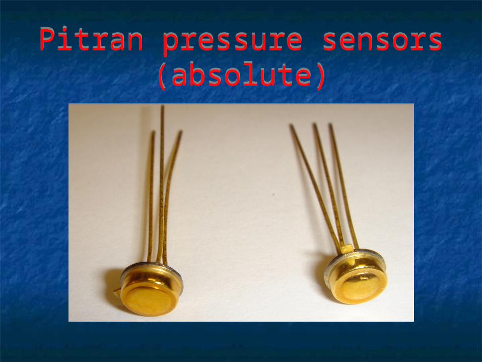
Pitran pressure sensors (absolute)
Pitran pressure sensors (absolute)

150 psi differential pressure sensor
150 psi differential pressure sensor

100 psi absolute pressure sensor (TO5 can)
100 psi absolute pressure sensor (TO5 can)
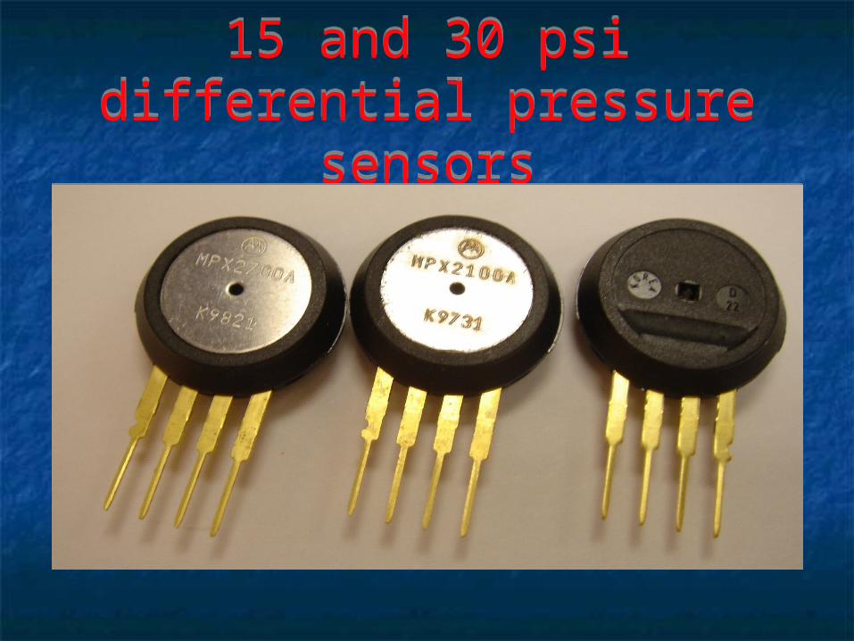
15 and 30 psi differential pressure sensors
15 and 30 psi differential pressure sensors
Capacitive pressure sensorsCapacitive pressure sensors
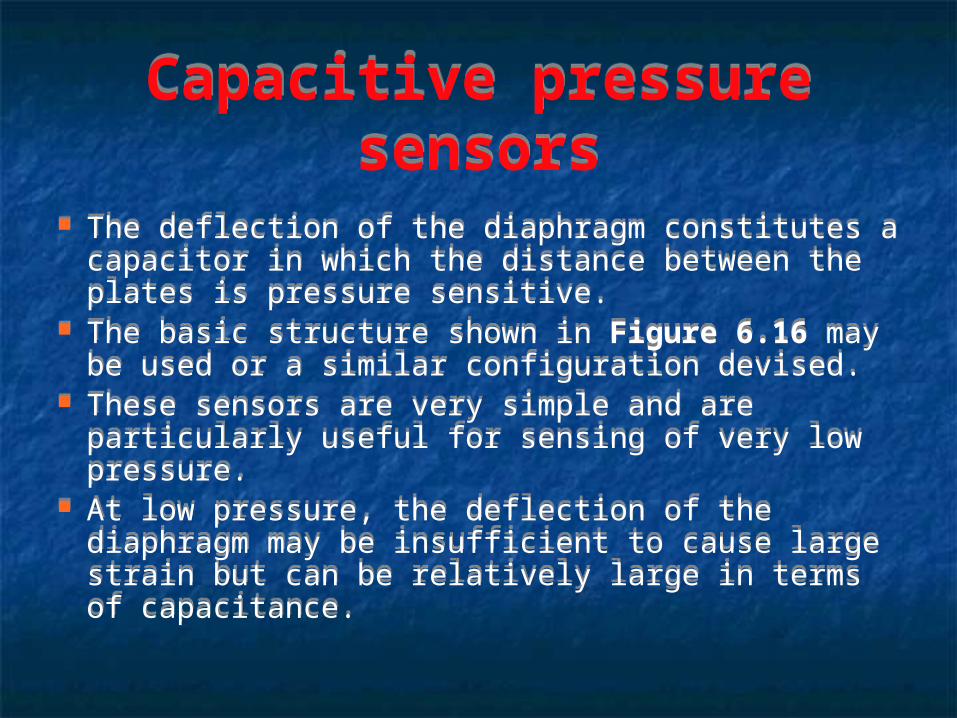
The deflection of the diaphragm constitutes a capacitor in which the distance between the plates is pressure sensitive.
The basic structure shown in Figure 6.16 may be used or a similar configuration devised.
These sensors are very simple and are particularly useful for sensing of very low pressure.
At low pressure, the deflection of the diaphragm may be insufficient to cause large strain but can be relatively large in terms of capacitance.

Capacitive pressure sensorsCapacitive pressure sensors
The capacitance may be part of an oscillator, The change in its frequency may be quite large making for
a very sensitive sensor. Other advantages
less temperature dependent stops on motion of the plate may be incorporated, - not sensitive
to overpressure. Overpressures of 2-3 orders of magnitude larger than
rated pressure may be easily tolerated without ill effects. The sensors are linear for small displacement but at larger
pressures the diaphragm tends to bow causing nonlinear output
Magnetic pressure sensorsMagnetic pressure sensors
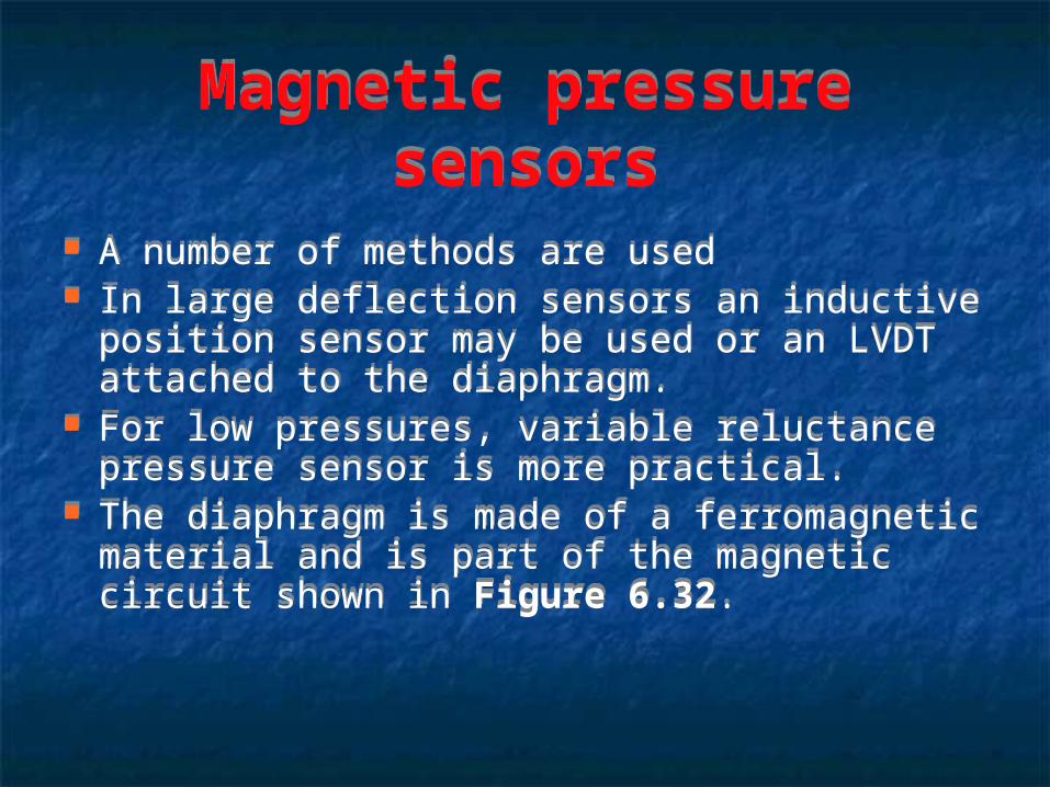
A number of methods are used In large deflection sensors an inductive position
sensor may be used or an LVDT attached to the diaphragm.
For low pressures, variable reluctance pressure sensor is more practical.
The diaphragm is made of a ferromagnetic material and is part of the magnetic circuit shown in Figure 6.32.

Variable reluctance pressure sensor
Variable reluctance pressure sensor

Magnetic pressure sensorsMagnetic pressure sensors
The reluctance is directly proportional to the length of the air gap between the diaphragm and the E-core.
Gap changes with pressure and the inductance of the two coils changes and sensed directly.
A very small deflection can cause a very large change in inductance of the circuit making this a very sensitive device.
Magnetic sensors are almost devoid of temperature sensitivity allowing these sensors to operate at elevated temperatures.

Other pressure sensorsOther pressure sensors
Optoelectronic pressure sensors - Fabri-Perot optical resonator to measure small displacements. light reflected from a resonant optical cavity is measured by
a photodiode to produce a measure of pressure sensed. A very old method of sensing low pressures (often
called vacuum sensors) is the Pirani gauge. based on measuring the heat loss from gases which is
dependent on pressure. The temperature is sensed and correlated to pressure, usually in an absolute pressure sensor arrangement.

Pressure sensors - propertiesPressure sensors - properties
Semiconductor based sensors can only operate at low temperatures (50 to +150C).
Temperature dependent errors can be high unless properly compensated (externally or internally).
The range of sensors can exceed 50,000 psi and can be as small as a fraction of psi.
Impedance is anywhere between a few hundred Ohms to about 100 kΩ, depending on device.
Linearity is between 0.1 to 2% typically

Pressure sensors - propertiesPressure sensors - properties
Other speciffications include: Maximum pressure, burst pressure and proof pressure
(overpressure) electrical output - either direct (no internal circuitry) or after
conditioning and amplification. Digital outputs are also available. Materials used (silicon, stainless steel, etc.) and compatibility
with gases and liquids are specified port sizes and shapes, connectors, venting ports cycling of the pressure sensors is also specified hysteresis (usually below 0.1% of full scale) repeatability (typically less than 0.1% of full scale).
GyroscopesGyroscopes
Gyroscopes come to mind usually as stabilizing devices in aircraft and spacecraft in such applications as automatic pilots.
Are much more than that and much more common than one can imagine.
The gyroscope is a navigational tool. Its purpose is to keep the direction of a device or vehicle.
Used in all satellites, in smart weapons and in all other applications that require attitude and position stabilization.
GyroscopesGyroscopes
Eventually will find their ways into consumer products such as cars.
They have already found their ways into toys. The basic principle involved is the principle of
conservation of angular momentum: “In any system of bodies or particles, the
total angular momentum relative to any point in space is constant, provided no external forces act on the system”

Mechanical GyroscopesMechanical Gyroscopes Best known of the existing gyros and the easiest to
understand. Consists of a rotating mass (heavy wheel) on an
axis in a frame - provides the angular momentum If one tries to change the direction of the axis, by
applying a torque to it, a torque is developed in directions perpendicular to the axis of rotation
This forces a precession motion. This precession is the output of the gyroscope and
is proportional to the torque applied to its frame.
Best known of the existing gyros and the easiest to understand.
Consists of a rotating mass (heavy wheel) on an axis in a frame - provides the angular momentum
If one tries to change the direction of the axis, by applying a torque to it, a torque is developed in directions perpendicular to the axis of rotation
This forces a precession motion. This precession is the output of the gyroscope and
is proportional to the torque applied to its frame.

Mechanical (rotor) gyroscopeMechanical (rotor) gyroscope
Mechanical GyroscopesMechanical Gyroscopes
A torque is applied to the frame of the gyro around the input axis,
The output axis will rotate as shown in a motion called precession.
This precession now becomes a measure of the applied torque and can be used as an output to, for example, correct the direction of an airplane or the position of a satellite antenna.
Application of torque in the opposite direction reverses the direction of precession.

Mechanical GyroscopesMechanical Gyroscopes
The relation between applied torque and the angular velocity of precession is:
The relation between applied torque and the angular velocity of precession is:
T = I ωΩ
T is the applied torque ω the angular velocity I the inertia of the rotating mass Ω is the angular velocity of precession. Iω is the angular momentum
Ω is a measure of the torque applied to the frame of the device
Mechanical GyroscopesMechanical Gyroscopes
Two or three axes gyroscope are built by duplicating this structure with rotation axes perpendicular to each other.
This type of gyroscope has been used for many decades in aircraft but:
it is a fairly large, heavy and complex not easily adapted to small systems. It also has other problems, associated with the
spinning mass (bearings, friction, balancing, etc.) Other devices have been developed

Coriolis force gyroscopesCoriolis force gyroscopes
Coriolis acceleration has been used to devise much smaller and more cost effective gyroscopic sensors.
Built in silicon by standard etching methods The rotating mass is replaced by a vibrating
body The coriolis acceleration is used for sensing.
The idea is based on the fact that if a body moves linearly in a rotating frame of reference, an acceleration appears at right angles to both motions as shown in Figure 6.34.
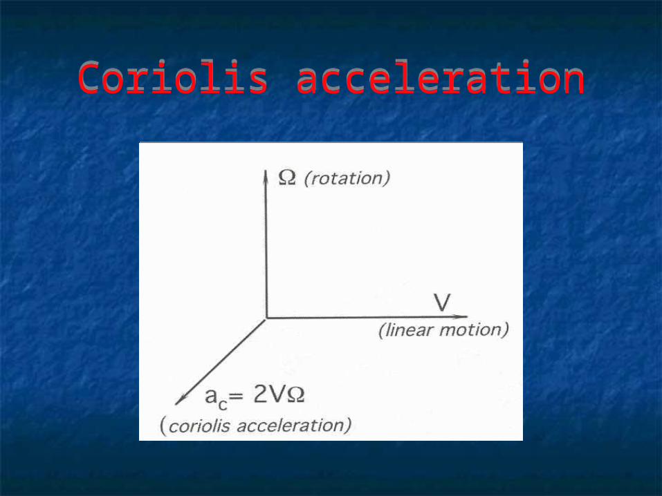
Coriolis accelerationCoriolis acceleration

Coriolis force gyroscopesCoriolis force gyroscopes
Linear motion is supplied by the vibration of a mass, usually a harmonic motion.
Under normal conditions, the coriolis acceleration is zero and the force associated with it is zero
If the sensor is rotated in the plane perpendicular to the linear vibration, an acceleration is obtained, proportional to the angular velocity Ω.
An example of a coriolis based gyroscope is shown next:
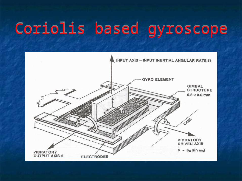
Coriolis based gyroscopeCoriolis based gyroscope
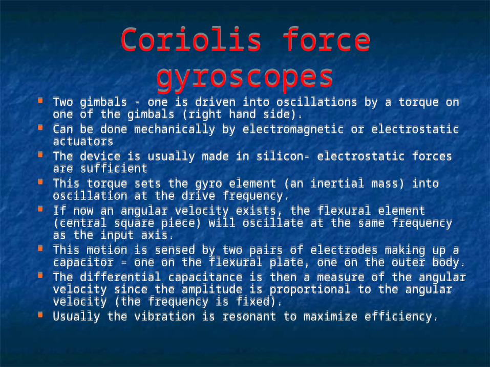
Coriolis force gyroscopesCoriolis force gyroscopes Two gimbals - one is driven into oscillations by a torque on one of the
gimbals (right hand side). Can be done mechanically by electromagnetic or electrostatic
actuators The device is usually made in silicon- electrostatic forces are sufficient This torque sets the gyro element (an inertial mass) into oscillation at
the drive frequency. If now an angular velocity exists, the flexural element (central square
piece) will oscillate at the same frequency as the input axis. This motion is sensed by two pairs of electrodes making up a
capacitor – one on the flexural plate, one on the outer body. The differential capacitance is then a measure of the angular velocity
since the amplitude is proportional to the angular velocity (the frequency is fixed).
Usually the vibration is resonant to maximize efficiency.
Two gimbals - one is driven into oscillations by a torque on one of the gimbals (right hand side).
Can be done mechanically by electromagnetic or electrostatic actuators
The device is usually made in silicon- electrostatic forces are sufficient This torque sets the gyro element (an inertial mass) into oscillation at
the drive frequency. If now an angular velocity exists, the flexural element (central square
piece) will oscillate at the same frequency as the input axis. This motion is sensed by two pairs of electrodes making up a
capacitor – one on the flexural plate, one on the outer body. The differential capacitance is then a measure of the angular velocity
since the amplitude is proportional to the angular velocity (the frequency is fixed).
Usually the vibration is resonant to maximize efficiency.

Optical GyroscopesOptical Gyroscopes
One of the more exciting developments in gyroscopes
Has no moving members. Used extensively for guidance and control Based on the Segnac effect. The Segnac effect is based on
propagation of light in optical fibers and can be explained using Figure 6.36.
One of the more exciting developments in gyroscopes
Has no moving members. Used extensively for guidance and control Based on the Segnac effect. The Segnac effect is based on
propagation of light in optical fibers and can be explained using Figure 6.36.

The Sagnac effectThe Sagnac effect
Sagnac effectSagnac effect
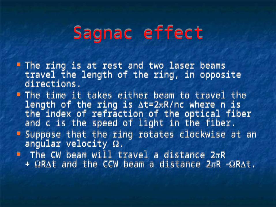
The ring is at rest and two laser beams travel the length of the ring, in opposite directions.
The time it takes either beam to travel the length of the ring is Δt=2R/nc where n is the index of refraction of the optical fiber and c is the speed of light in the fiber.
Suppose that the ring rotates clockwise at an angular velocity Ω.
The CW beam will travel a distance 2R +ΩRΔt and the CCW beam a distance 2R ΩRΔt.
Sagnac effectSagnac effect
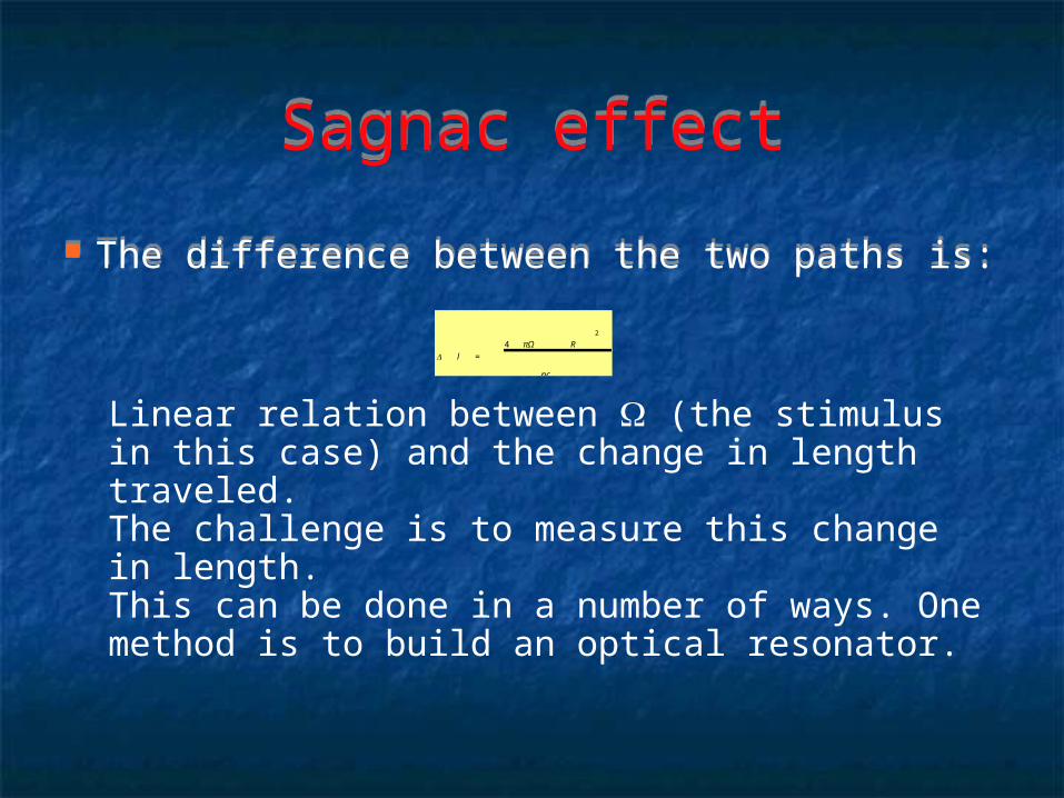
The difference between the two paths is: The difference between the two paths is:
Linear relation between Ω (the stimulus in this case) and the change in length traveled. The challenge is to measure this change in length. This can be done in a number of ways. One method is to build an optical resonator.
Δ l =
4 πΩ R
2
nc

Resonant fiber optic gyroscopeResonant fiber optic gyroscope
A resonator is any device which has a dimension equal to multiple half wavelengths of the wave.
A ring is built as follows:
A resonator is any device which has a dimension equal to multiple half wavelengths of the wave.
A ring is built as follows:
Resonant fiber optic ring resonator
Resonant fiber optic ring resonator
Light is coupled through the light coupler (beam splitter). At resonance, which depends on the circumference of
the ring, maximum power is coupled into the ring and minimum power is available at the detector.
The incoming beam frequency is tuned to do just that. If the ring rotates at an angular velocity Ω, the light
beams in the ring change in frequency (wavelength) to compensate for the change in apparent length of the ring.
Resonant fiber optic ring resonator
Resonant fiber optic ring resonator
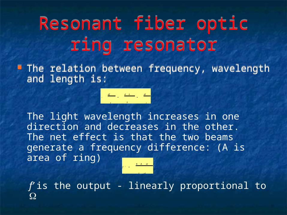
The relation between frequency, wavelength and length is:
The relation between frequency, wavelength and length is:
−
df
f
=
d λ
λ
=
dl
l
The light wavelength increases in one direction and decreases in the other. The net effect is that the two beams generate a frequency difference: (A is area of ring)
f ' =
4 A Ω
λ nl
f’ is the output - linearly proportional to Ω

Coil optical fiber gyroscopeCoil optical fiber gyroscope The resonator is replaced by a coiled optical
fiber Fed from a polarized light source through a
beam splitter to ensure equal intensity and phase (the phase modulator adjusts for any variations in phase between the two beams).
The resonator is replaced by a coiled optical fiber
Fed from a polarized light source through a beam splitter to ensure equal intensity and phase (the phase modulator adjusts for any variations in phase between the two beams).
Coil optical fiber gyroscopeCoil optical fiber gyroscope
The beams propagate in opposite directions
When returning to the detector, they are at the same phase in the absence of rotation.
If rotation exists, the beams will induce a phase difference at the detector which is dependent of the angular frequency Ω.
The beams propagate in opposite directions
When returning to the detector, they are at the same phase in the absence of rotation.
If rotation exists, the beams will induce a phase difference at the detector which is dependent of the angular frequency Ω.

Coil optical fiber gyroscopeCoil optical fiber gyroscope
Optical gyroscopes are not cheap But they are orders of magnitude cheaper than the
spinning mass gyroscope and much smaller and lighter. Have a very large dynamic range (as high as 10000) and
so they can be used for sensing angular frequency over a large span.
Optical fiber gyroscopes are immune to electromagnetic fields as well as to radiation and hence can be used in very hostile environments including space