MECHANICAL SCIENTIFIC ENGINEERING · PDF fileKontekst, podgotovka, proekten menaxment i...
70
UDC 621 CODEN: MINSC5 ISSN 1857 – 5293 MECHANICAL ENGINEERING MA[INSKO IN@ENERSTVO SCIENTIFIC JOURNAL NAU^NO SPISANIE Volume 27 Number 2 Skopje, 2008
Transcript of MECHANICAL SCIENTIFIC ENGINEERING · PDF fileKontekst, podgotovka, proekten menaxment i...

UDC 621CODEN: MINSC5 ISSN 1857 – 5293
MECHANICAL ENGINEERING
MA[INSKO
IN@ENERSTVO
SCIENTIFIC JOURNAL NAU^NO SPISANIE
Volume 27 Number 2 Skopje, 2008

Mech. Eng. Sci. J. Vol. No. pp. Skopje 27 2 51‡124 2008Ma{. in`. nau~. spis. God. Broj str. Skopje
MA[INSKO IN@ENERSTVO ‡ NAU^NO SPISANIE MECHANICAL ENGINEERING – SCIENTIFIC JOURNAL
Izdava Ma{inski fakultet, Univerzitet „Sv. Kiril i Metodij“, Skopje, R. Makedonija
Published by Faculty of Mechanical Engineering, "SS. Cyril and Methodius" University, Skopje, R. Macedonia
Izleguva dva pati godi{no ‡ Published twice yearly
UREDUVA^KI ODBOR EDITORIAL BOARD
Odgovoren urednik Editor in Chief Prof. d-r. Ivan Mickovski Prof. Ivan Mickovski, Ph.D.
Zamenik odgovoren urednik Co-editor in Chief Von. prof. d-r Valentina Ge~evska Assoc. Prof. Valentina Gečevska, Ph.D.
Urednici Editors
Von. prof. d-r Nikola Tuneski, sekretar Assoc. Prof. Nikola Tuneski, Ph.D., secretary Prof. d-r Dobre Run~ev Prof. Dobre Runčev, Ph.D.
Prof. d-r Slave Armenski Prof. Slave Armenski, Ph.D. Prof. d-r Janko Jan~evski Prof. Janko Jančevski, Ph.D.
Von. prof. d-r Jasmina ^alovska Assoc. Prof. Jasmina Čalovska, Ph.D. Doc. d-r Zoran Markov Ass. Prof. Zoran Markov, Ph.D.
Tehni~ki urednik Technical editor managing
Blagoja Bogatinoski Blagoja Bogatinoski
Lektura Lectors Ilinka Grubovi}
(angliski)Ilinka Grubović (English)
Georgi Georgievski (makedonski)
Georgi Georgievski (Macedonian)
Korektor Proof-reader Alena Georgievska Alena Georgievska
UDK: NUB „Kliment Ohridski“ ‡ Skopje
(Oqa Stojanova)UDC: "St. Kliment Ohridski" Library – Skopje (Olja Stojanova)
Tira`: 300 Copies: 300 Cena: 520 denari Price: 520 denars
Adresa Address
Ma{inski fakultet Faculty of Mechanical Engineering (Ma{insko in`enerstvo ‡ nau~no spisanie) (Mechanical Engineering – Scientific Journal)
Odgovoren urednik Editor in Chief po{t. fah 464 P.O.Box 464
MK-1001 Skopje, Republika Makedonija MK-1001 Skopje, Republic of Macedonia Mech. Eng. Sci. J. is indexed/abstracted in INIS (International Nuclear Information System)
www.mf.ukim.edu.mk

MA[INSKO IN@ENERSTVO ‡ NAU^NO SPISANIE MA[INSKI FAKULTET, SKOPJE, REPUBLIKA MAKEDONIJA
MECHANICAL ENGINEERING – SCIENTIFIC JOURNAL
FACULTY OF MECHANICAL ENGINEERING, SKOPJE, REPUBLIC OF MACEDONIA
Mech. Eng. Sci. J. Vol. No. pp. Skopje 27 2 51‡124 2008Ma{. in`. nau~. spis. God. Broj str. Skopje
S O D R @ I N A
393 ‡ \or|i Axiev, Vladimir Gliha, Tomaž Vuherer, Elisaveta Don~eva
Vlijanie na tipot na prsnatina na lomno odnesuvawe na zavareni SENB-primeroci od mikrolegiran ~elik................................................................. 51‡57
394 ‡ Jasmina ^aloska, Davor Karaka{ev, Atanas Ko~ov, Bor~e Stojkov 3D digitalizacija vo ortopedijata ...........................................................................59‡65
395‡ Iskra Dukovska-Popovska Kontekst, podgotovka, proekten menaxment i dijalog vo procesot na razvoj na proizvodstvena vizija.......................................................................... 67‡76
396 ‡ Goran Milo{ovski, Cees Bil, Milan ]osevski Primena na ekspertski sistemi vo istraga na avionski nezgodi......................... 77‡95
397 ‡ Goran Milo{ovski, Cees Bil, Paul Simon, Milan ]osevski Ekspertski sistem za istraga na avionski nezgodi ............................................. 97‡105
398 ‡ Filip Mojsovski Nivo na vlagata vo psihrometriski procesi ...................................................... 107‡112
399 ‡ Chang-Hou Lu, Guo-Liang Lu, Zhu-Yan Xu, Huai-Bo Song, Zoran Pandilov Prepoznavawe na znaci (karakteri) vtisnati vo metal.................................... 113‡121
Upatstvo za avtorite ..................................................................................................... 123‡124

MECHANICAL ENGINEERING – SCIENTIFIC JOURNAL FACULTY OF MECHANICAL EGINEERING, SKOPJE, REPUBLIC OF MACEDONIA
MA[INSKO IN@ENERSTVO ‡ NAU^NO SPISANIE
MA[INSKI FAKULTET, SKOPJE, REPUBLIKA MAKEDONIJA
Mech. Eng. Sci. J. Vol. No. pp. Skopje 27 2 51‡124 2008Ma{. in`. nau~. spis. God. Broj str. Skopje
C O N T E N T S
393 – Gjorgji Adžiev, Vladimir Gliha, Tomaž Vuherer, Elisaveta Dončeva Crack tip size effect on the fracture behaviour of welded SENB specimens of micro-alloyed steel .................................................................................................... 51–57
394 – Jasmina Čaloska, Davor Karakašev, Atanas Kočov, Borče Stojkov 3D digitalization in orthopedics ..................................................................................... 59–65
395 – Iskra Dukovska-Popovska Considering the context, setup, project management and dialogue in manufacturing vision development processes ...................................................................................... 67–76
396 – Goran Milošovski, Cees Bil, Milan Ćosevski Application of expert systems to aircraft accident investigation..................................... 77–95
397 – Goran Milošovski, Cees Bil, Paul Simon, Milan Ćosevski Demonstration of expert systems to aircraft accident investigation ............................. 97–105
398 – Filip Mojsovski Humidity level in psychrometric processes................................................................ 107–112
399 – Chang-Hou Lu, Guo-Liang Lu, Zhu-Yan Xu, Huai-Bo Song, Zoran Pandilov Metal label character recognition ............................................................................... 113–121
Instructions for authors ................................................................................................... 123–124 Mech. Eng. Sci. J. 27 (2), 51–124 (2008)

Mechanical Engineering – Scientific Journal, Vol. 27, No. 2, pp. 51–57 (2008) CODEN: MINSC5 – 393 ISSN 1857–5293 Received: September 26, 2008 UDK: 539.219.2:[621.642:621.791 Accepted: October 7, 2008 621.791.05:539.219.2
Original scientific paper
CRACK TIP SIZE EFFECT ON THE FRACTURE BEHAVIOUR OF WELDED SENB SPECIMENS OF MICRO-ALLOYED STEEL
Gjorgji Adžiev1, Vladimir Gliha2, Tomaž Vuherer2, Elisaveta Dončeva1
1Faculty of Mechanical Engineering,"SS Cyril and Methodius" University, P.O Box 464, MK-1001 Skopje, Republic of Macedonia
2Faculty of Mechanical Engineering, University of Maribor, Smetanova ulica 17, Maribor, Slovenia
A b s t r a c t: The HAZ fracture behavior of the weld-ments of HSLA steel for pressure vessels has been investi-gated. Having in mind the purpose of such a structure, the welded joint should possess sufficient resistance towards crack occurrence as well its propagation. The analysis encompassed impact toughness testing the Charpy specimens and fracture toughness determination of SENB specimens of base metal and simulated microstructures of HAZ, and finally fracture toughness testing the welded specimens with the crack located in the very narrow HAZ regions. The analysis revealed the effect of the crack tip (electro eroded or fatigued) on the onset of the stabile crack growth for the different microstructures. The comparative analysis between the testings showed the influence of the mismatch towards the fracture behavior of real welded joint in respect of simulated microstructures.
Key words: impact energy, HAZ, crack, stabile crack growth, fracture, mismatch.
1. INTRODUCTION
Most of the general industrial facilities which are utilised in various sectors such as the transpor-tation industry, power generation, liquid and gas storage facilities, offshore structures etc., comprise welded structures i.e. welded joints, too, which are very sensitive parts of the structure due to the fact that the welded joints are being produced and op-erate in complex metallurgical and stress condi-
tions. In the beginning of the previous century, the design of structures was based on tensile strength and ductility. The development of high strength micro-alloyed and low alloy steels as well as new fabrication technologies, changed the approach of the design engineers to design structures on the basis of yield strength and fracture toughness in-stead of tensile strength [1].
In this article the fracture resistance of typical HAZ microstructures, revealed by impact testing and standard fracture toughness testing, as well as fracture behavior of welded joints with the crack in HAZ, is investigated taking into account the type of the crack and the influence of the neighboring microstructural regions on the crack propagation.
It refers to the steel quality T StE 420 with in-creased strength, strengthened through a grain re-finement mechanism due to the micro-alloying process, with the following main mechanical prop-erties: ReH = 420 MPa, Rm = 604 MPa and A5 = 25%. The content of carbon and titanium is typical, as shown in Table 1, the content of C (0.2%) is relatively high for such a steel grade, contributing to the strength increase, whereas the grain refinement and achieving a good correlation between the strength and plasticity are achieved by the titanium content of 0.12%.
T a b l e 1 Chemical Composition of the Steel
C % Si % Mn % P % S % Ti % Cr % Al % Cu % Ni % V % Mo % Nb %
0.2 0.44 1.35 0.012 0.01 0.12 0.15 0.06 0.05 0.1 0.008 0.015 0.001

52 Gj. Adžiev, V. Gliha, T. Vuherer, E. Dončeva
Mech. Eng. Sci. J., 27 (2), 51–57 (2008)
2. EXPERIMENTAL
For the purposes of this investigation, the fol-lowing specimen types were machined:
a) V-notched standard Charpy specimens, for the scope of impact toughness testing on simulated microstructures of HAZ,
b) standard small SENB specimens (8×14.8×70 mm) for determination of fracture toughness on simulated HAZ microstructures (Fig. 1),
c) standard SENB specimens for determina-tion of fracture toughness of HAZ cracked welded joints (Fig. 2).
The simulation of the welding thermal cycles by controlled heating and cooling has been con-ducted on the thermal simulating device type SMITWELD (Thermal cycle simulator) TCS 1405, equivalent to the real process of welding. After the first cycle of 1305 ºC, a double simulation is done, up to 780 ºC and 960 ºC, which produced two typi-
cal microstructural regions of HAZ of a multilayer welded joint, containing the cracks in HAZ. The simulated specimens are preheated at 200 ºC, sub-sequently heated at the assigned temperature and cooled with Δt8/5 ≈ 15 s for fine-grained HAZ 1350/960 ºC, respectively cooled with Δt8/5 ≈ 60 s for 1350/780 ºC for the coarse-grained HAZ. Two types of crack tip are produced one by fatigue pre-cracking and anotherr one by electro erosion in order to determine the influence of the crack tip type (Fig. 1).
The welded SENB (24×24×110 mm) speci-mens are made according to Fig. 2, with cracks produced by electro erosion and located in the fine-grained HAZ and coarse-grained HAZ near the fusion line. The determination of mechanical prop-erties of the weldment microstructural regions is encompassed by utilisation of microhardness measurement and application of the Ramberg-Osgood law, Table 2.
a) fatigue crack
b) electroeroded crack
Fig. 1. Shape and dimensions of small SENB specimens
10~
2
5
10~
2
5
10~
2
a) crack tip in coarse-grained HAZ
b) crack tip in fine-grained HAZ
Fig. 2. Standard SENB specimen

Crack tip size effect on the fracture behaviour of welded SENB specimens of micro-alloyed steel 53
Ma{. in`. nau~. spis., 27 (2), 51‡57 (2008)
T a b l e 2
Microhardness measurement and mismatch determination
a) Measuring lines of microhardness b) Mismatch coefficients
material HV1 Rp0.2 MPa
Rm MPa
A5 %
M, mismatch
BM 185 4201) 6041) 251) - WMfill 205 478 669 16.9 1.14 WMroot 212 500 692 16.2 1.19 WMcover 215 509 702 15.9 1.21 CG HAZ 281 605 1170 8.4 0.79
FG HAZ 221 461 904 11.6 1.04
1) experimentally obtained value
The method used for fracture toughness test-
ing, evaluation and interpretation of the results, is done according to ASTM E 1820/ E 1152/ E 1290/ E 1737, [2–5].
3. RESULTS AND DISCUSSIONS
3.1. Investigation of impact toughness on simulated specimens
The investigation has been performed at the temperature of –40 ºC (only the base metal), –20 and +20 ºC.
The base material reveals good toughness having in mind its ferritic-perlitic structure. One
should notice that both components of the total energy are approximately at the same level at +20 ºC, which means high capability of plastic de-formation, but at the same time indicates stable propagation of the initial crack, i.e. high resistance towards total failure. The decrease of the tempera-ture obviously leads to toughness decreasing, as a result of the reduced plasticity but still both com-ponents of the energy are of approximate level. At –40 ºC, the unstable fracture occurs at the exact same moment when a crack is initiated, as a result of meaning reduction of the energy used for the crack growth in the correlation with the one used for initiation, Fig. 3.
–40 ºC –20 ºC +20 ºC
-5
0
5
10
15
20
25
30
35
0 1 2 3 4 5
t [ms]
F [k
N]
-51535557595115135155175195
E [J
]
-5
0
5
10
15
20
25
30
35
0 1 2 3 4 5
t [ms]
F [k
N]
-51535557595115135155175195
E [J
]
-5
0
5
10
15
20
25
30
35
0 1 2 3 4 5
t [ms]
F [k
N]
-51535557595115135155175195
E [J
]
Fig. 3. F vs. t curve for impact toughness testing of the base metal
The double cycled fine-grained structure 1350/960 ºC reveals satisfactory impact toughness which could be regarded as expected, since such microstructure has experienced partial or full nor-malization. Nevertheless, at –720 ºC the energy share used for the crack growth is almost zero, and
besides the fact that the total energy is on a satis-factory level over 27 J, meaning that there is still ability for absorption of the plastic strain, immedi-ately after the crack initiation the collapse occurs through brittle fracture, Fig. 4.
54 Gj. Adžiev, V. Gliha, T. Vuherer, E. Dončeva
Mech. Eng. Sci. J., 27 (2), 51–57 (2008)
–20 ºC +20 ºC
-5
0
5
10
15
20
25
30
35
0 1 2 3 4 5
t [ms]
F [k
N]
-5
15
35
55
75
95
115
135
E [J
]
-5
0
5
10
15
20
25
30
35
0 1 2 3 4 5
t [ms]
F [k
N]
-5
15
35
55
75
95
115
135
E[J
]
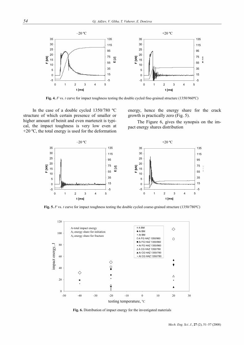
Fig. 4. F vs. t curve for impact toughness testing the double cycled fine-grained structure (1350/960ºC)
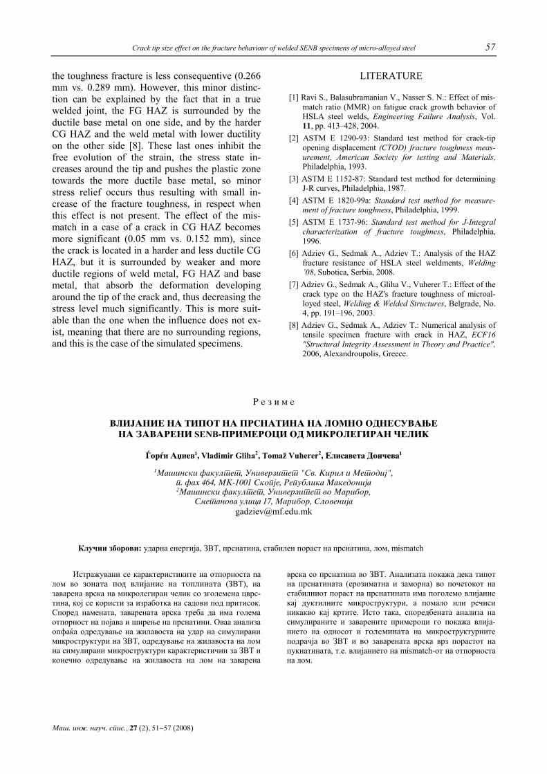
In the case of a double cycled 1350/780 ºC structure of which certain presence of smaller or higher amount of beinit and even martenzit is typi-cal, the impact toughness is very low even at +20 ºC, the total energy is used for the deformation
energy, hence the energy share for the crack growth is practically zero (Fig. 5).
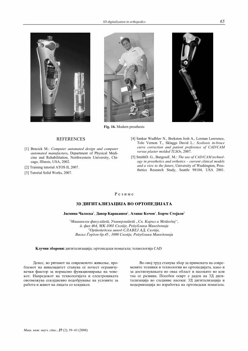
The Figure 6, gives the synopsis on the im-pact energy shares distribution
–20 ºC +20 ºC
-5
0
5
10
15
20
25
30
35
0 1 2 3 4 5
t [ms]
F [k
N]
-5
15
35
55
75
95
115
135
E [J
]
-5
0
5
10
15
20
25
30
35
0 1 2 3 4 5
t [ms]
F [k
N]
-5
15
35
55
75
95
115
135
E[J
]Fig. 5. F vs. t curve for impact toughness testing the double cycled coarse-grained structure (1350/780ºC)
0
20
40
60
80
100
120
-50 -40 -30 -20 -10 0 10 20 30
testing temperature, oC
impa
ct e
nerg
y, J
A BMAi BMAt BMA FG HAZ 1350/960Ai FG HAZ 1350/960At FG HAZ 1350/960A CG HAZ 1350/780Ai CG HAZ 1350/780At CG HAZ 1350/780
A-total impact energyAi-energy share for initiationAt-energy share for fracture
Fig. 6. Distribution of impact energy for the investigated materials

Crack tip size effect on the fracture behaviour of welded SENB specimens of micro-alloyed steel 55
Ma{. in`. nau~. spis., 27 (2), 51‡57 (2008)
3.2. Fracture toughness determination on simulated SENB specimens
The investigation is conducted on specimens made of basic metal as well as on specimens with simulated HAZ microstructures. For each kind of microstructure, two types of specimens are pre-pared: fatigue precracked and electroeroded, in order to obtain the effect of the crack tip type, con-sidering the fact that the cracks in the welded specimens are produced and accurately located in HAZ by electroerosion, whereas the real cracks in welds are of greater sharpness.
In the case of base metal, all specimens exhibit crack initiation and its stabile propagation, one should notice in the case of electroeroded initial crack, the stabile crack propagation occurred at higher value of CTOD i.e. δIc ≈ 0.57 mm, whereas in the case of fatigue precracked specimens the corre-sponding value of CTOD is δIc ≈ 0.31 mm. The rea-son for such behavior could be explained by the effect of the greater size of the tip in case of electro-eroded crack, thus causing the plastic strain to be dis-tributed in larger volume enabling higher values of tip opening before the plasticity of the material is being exceeded. Respectively, in the case of fa-tigue precracked specimens, due to the smaller size of the tip, the strain was distributed in a volume of smaller size, thus exceeding the plasticity of the
material at lower value of tip opening. This con-firms the effect of the crack tip radius, and such effect could be expressed by the following term for correlative ratio: Δδ = δIc,fatigue / δIc,erosive = 0.544 (Fig. 7).
Likewise, the simulated specimens with double cycled fine-grained microstructure of 1350/960 ºC exhibit behavior of which the same establishments can be utilized, with smaller differences on the magnitude of CTOD at the beginning of the stable growth. The specimens with electroeroded crack have a value ofδIc ≈ 0.266 mm and the fatigued precracked have δIc ≈ 0.160 mm, thus resulting in a correlative ratio of Δδ = 0.6 (Fig. 7).
The last set of specimens, the simulated dou-ble cycled 1350/780 ºC coarse-grained microstruc-ture exhibited no stable crack growth, meaning that Δa = 0. However, the unstable failure occurred at δc ≈ 0.05 mm and δc ≈ 0.04 mm, respectively for electroeroded specimens and for fatigue pre-cracked. The formerly established correlative ratio for this case is Δδ = 0.8 (Fig. 7). This value shows that, although there is no stable crack growth in the coarse-grained microstructure, there has been slightly higher plastic deformation around the tip of the electroeroded crack compared with almost zero around fatigue precracked specimen leading to unstable failure.
0.4 0.5 0.6 0.7 0.8 0.9 1 1.1
correlative ratio
toug
hnes
s
base metal (BM)
intercritical coarsegrained HAZ (ICCG HAZ
coarsegrained HAZ (CG HAZ)
finegrained HAZ (FG HAZ)
Fig. 7. Correlation between fatigued and electroeroded crack
3.3. Fracture toughness investigation on SENB welded specimens with crack in HAZ
The base metal specimens reveal likewise be-haviour, i.e. resulting with higher value of CTOD
at the beginning of the crack propagation for the electroeroded specimens compared with fatigued precracked ones [6]. One can say, this coincides with the analysis of the simulated specimens in the previous chapter. Nevertheless, after the beginning

56 Gj. Adžiev, V. Gliha, T. Vuherer, E. Dončeva
Mech. Eng. Sci. J., 27 (2), 51–57 (2008)
of the stable crack growth the influence of the tip disappears and the resistance curve in the case of fatigue or erosive cracks obtains equal slope [7]. The value of CTOD in the beginning of the stable crack growth, for electroeroded specimens is δIc = 0.544 mm, and for fatigue precracked ones is δIc = 0.3 mm. This gives a value of correlative ratio Δδ = 0.552 which is almost identical with the one determined for the small non-standard specimens
and this indicates that the effect of the specimen size does not affect the fracture behaviour signifi-cantly.
It is worth-like to note that for the case of welded specimens, after the crack initiates in the domain microstructure, it always propagates to-wards the base metal, i.e. microstructure with higher ductility, hence protecting the welded joint from brittle fracture (Fig. 8).
weld metal
FG HAZ
CG HAZ
a) crack tip in FG HAZ b) crack tip in CG HAZ c) crack shifting
Fig. 8. Crack shifting and propagation towards base metal
The value of CTOD at the beginning of the stable crack growth in case of welded specimens with a crack in a fine-grained HAZ is δIc = 0.289 mm, respectively CTOD in case of a crack in a coarse-grained HAZ is δIc = 0.152 mm.
By taking into consideration the previously established correlative ratio, one could implement the values of Δδ determined for the simulated mi-crostructures into the values determined for the welded specimens with electroeroded cracks lo-cated with accuracy in the narrow regions of the HAZ, i.e. Δδ = 0.6 for FG HAZ, and Δδ = 0.80 for CG HAZ. The values of the fracture toughness with implemented correction are as follows: δIc = 0.173 mm for FG HAZ and δIc = 0.122 mm for CG HAZ.
4. CONCLUSION
One can say, the values of the correlative ra-tio for the micro-alloyed highstrength fine-grained steel T StE 420 are as follows: 0.55 for the ductile base material, 0.60 for double cycled (1350/960 oC) normalized fine-grained microstructure, 0.8 for double cycled (1350/780 oC) critical coarse-grained microstructure and 1.0 for one-cycled (1350 oC) coarse-grained microstructure. This
means that the effect of crack tip type is as mean-ingful as the ductility or toughness of the investi-gated material is higher. The obtained correlation is very significant for determination of the real fracture resistance of welded joint containing crack in HAZ. The real cracks in materials are character-ized with tips of very high sharpness. Since the experimental research of the fracture behavior of weldment's HAZ require production of cracks lo-cated in the specific region of HAZ, with very small dimensions and volume as well as irregular geometry, the production of electroeroded instead of standardized fatigue cracks is necessary.
In case of welded specimens, the small over-match of the weld has played a protective role in such way that inhibited the crack growth towards the brittle structure, CG HZT or the weld metal. In both cases the crack has shifted towards the base metal with higher ductility thus decreasing the speed of propagation.
Furthermore, one can say that the influence of the size of the microstructural region containing the crack, i.e. the difference between the initiation of the stable crack growth in case when the crack is located in rather big volume compared with the case when it is located in a very narrow region, comes in the first place. When the crack is in FG HAZ of a real welded joint the mismatch effect on
Crack tip size effect on the fracture behaviour of welded SENB specimens of micro-alloyed steel 57
Ma{. in`. nau~. spis., 27 (2), 51‡57 (2008)
the toughness fracture is less consequentive (0.266 mm vs. 0.289 mm). However, this minor distinc-tion can be explained by the fact that in a true welded joint, the FG HAZ is surrounded by the ductile base metal on one side, and by the harder CG HAZ and the weld metal with lower ductility on the other side [8]. These last ones inhibit the free evolution of the strain, the stress state in-creases around the tip and pushes the plastic zone towards the more ductile base metal, so minor stress relief occurs thus resulting with small in-crease of the fracture toughness, in respect when this effect is not present. The effect of the mis-match in a case of a crack in CG HAZ becomes more significant (0.05 mm vs. 0.152 mm), since the crack is located in a harder and less ductile CG HAZ, but it is surrounded by weaker and more ductile regions of weld metal, FG HAZ and base metal, that absorb the deformation developing around the tip of the crack and, thus decreasing the stress level much significantly. This is more suit-able than the one when the influence does not ex-ist, meaning that there are no surrounding regions, and this is the case of the simulated specimens.
LITERATURE
[1] Ravi S., Balasubramanian V., Nasser S. N.: Effect of mis-match ratio (MMR) on fatigue crack growth behavior of HSLA steel welds, Engineering Failure Analysis, Vol. 11, pp. 413–428, 2004.
[2] ASTM E 1290-93: Standard test method for crack-tip opening displacement (CTOD) fracture toughness meas-urement, American Society for testing and Materials, Philadelphia, 1993.
[3] ASTM E 1152-87: Standard test method for determining J-R curves, Philadelphia, 1987.
[4] ASTM E 1820-99a: Standard test method for measure-ment of fracture toughness, Philadelphia, 1999.
[5] ASTM E 1737-96: Standard test method for J-Integral characterization of fracture toughness, Philadelphia, 1996.
[6] Adziev G., Sedmak A., Adziev T.: Analysis of the HAZ fracture resistance of HSLA steel weldments, Welding ’08, Subotica, Serbia, 2008.
[7] Adziev G., Sedmak A., Gliha V., Vuherer T.: Effect of the crack type on the HAZ's fracture toughness of microal-loyed steel, Welding & Welded Structures, Belgrade, No. 4, pp. 191–196, 2003.
[8] Adziev G., Sedmak A., Adziev T.: Numerical analysis of tensile specimen fracture with crack in HAZ, ECF16 "Structural Integrity Assessment in Theory and Practice", 2006, Alexandroupolis, Greece.
R e z i m e
VLIJANIE NA TIPOT NA PRSNATINA NA LOMNO ODNESUVAWE NA ZAVARENI SENB-PRIMEROCI OD MIKROLEGIRAN ^ELIK
\or|i Axiev1, Vladimir Gliha2, Tomaž Vuherer2, Elisaveta Don~eva1
1Ma{inski fakultet, Univerzitet "Sv. Kiril i Metodij", p. fah 464, MK-1001 Skopje, Republika Makedonija 2Ma{inski fakultet, Univerzitet vo Maribor,
Smetanova ulica 17, Maribor, Slovenija [email protected]
Клучни зборови: ударна енергија, ЗВТ, прснатина, стабилен пораст на прснатина, лом, mismatch
Истражувани сe карактеристиките на отпорноста na лом во zonata pod vlijanie na toplinata (ЗВТ), на заварена врска на микролегиран челик со зголемена цврс-тина, кој се користи за изработка на садови под притисок. Според намената, заварената врска треба да има голема отпорност на појава и ширење на прснатини. Оваа анализа опфаќа одредување на жилавоста на удар на симулирани микроструктури на ЗВТ, одредување на жилавостa на лом на симулирани микроструктури карактеристични за ЗВТ и конечно одредување на жилавостa на лом на заварена
врска со прснатина во ЗВТ. Анализата покажа дека типот на прснатината (ерозиматна и заморна) во почетокот на стабилниот пораст на прснатината има поголемо влијание кај дуктилните микроструктури, а помало или речиси никакво кај кртите. Исто така, споредбената анализа на симулираните и заварените примероци го покажа влија-нието на односот и goleminata на микроструктурните подрачја во ЗВТ и vo заваренaтa врскa врз порастот на пукнатината, т.е. влијанието на mismatch-от на отпорноста на лом.

Mechanical Engineering – Scientific Journal, Vol. 27, No. 2, pp. 59–65 (2008) CODEN: MINSC5 – 394 ISSN 1857–5293 Received: September 19, 2008 UDC:617.3–77:004 Accepted: October 12, 2008
Original scientific paper
3D DIGITALIZATION IN ORTHOPEDICS
Jasmina Čaloska1, Davor Karakašev1, Atanas Kočov1, Borče Stojkov2 1Faculty of Mechanical Engineering, SS Cyril and Methodius University,
P.O. Box 464, MK-1001 Skopje, Republic of Macedonia 2Slavej Ltd , Orthopedic and Prosthetic Centre,
Vasil Gjorgov,45, MK-1000 Skopje, Republic of Macedonia [email protected]
A b s t r a c t: Nowadays, in the rhythm of modern ex-istence, the disability problem becomes more frequent restric-tive cause for normal living of the man with disabilities. The development of technology and electronics enables everyday improvement of the living and working conditions of the men with disabilities. This work emphasizes the sophisticated tech-niques and technologies in orthopedics, the achievements in this area and the future developments. It focuses on the 3D digitalization with particular emphasis on the following items: 3D digitalization and modernization in the procedures and identification, and production of the orthopedic aids.
Key wоrds: digitalization; orthopedic aids; CAD technology
1. INTRODUCTION
Since the beginning of the history of man-kind, people have been using different types of artificial devices as a replacement of the lost ex-tremities.
Archaeological findings and written documents confirm that the ancient people used to make am-putations of extremities as a result of many wars and the law enforcement in that period.
There are written historical data that were found a 300 years BC, which describe rough pros-thesis made as a replacement of the missing lower extremities. They were made from metal plates nailed on a piece of wood.
In the beginning prosthesis were produced by the blacksmiths and weapon manufacturers.
The earliest scientific data about prosthesis made and applied by a physician were published in France in 1579 in a book written by the French
surgeon Ambroise Paré (1510–1590) (Fig. 1) where he describes prosthesis applied to a person on whom he had made amputation as a military sur-geon.
Fig.1. Ambroise Paré
The greatest development was accomplished during and after the Second Word War. Then new and light materials, for that period of time (such as aluminum and plastic), were used for the produc-tion of prosthesis for the first time (Fig. 2).
75% of the causes for amputations are ill-nesses such as cancer, circulation disorder related to diabetes, while 25% are accidents and a very small part is congenital.

60 J. Čaloska, D. Karakašev, A. Kočov, B. Stojkov
Mech. Eng. Sci. J., 27 (2), 59–65 (2008)
Fig. 2. Beginnings of the applying prostheses
2. ABOUT 3D DIGITALIZATION
3D Digitalization’s first usage was for the needs of the military, or to be more precise, this type of technology was developed in NASA labo-ratories. The first thing that had been made was digitalization of objects into the space as a research for their characteristics in a virtual environment.
The result of the digitalization is classical data which actually represents "cloud of points", that can be further processed depending on the re-quirements. Basic resources (for digitalization) are scanners and cameras which are optical, with lasers or sensors.
3. USAGE OF 3D DIGITALIZATION
The implementation of 3D Digitalization into the modern world solves more than the possible and the fields of its usages are unlimited.
3D Digitalization in the field of mechanical engineering and medicine is very important, as well as in the other fields and aspects of human life.
The development in the medicine has brought important results and relieving circumstances in diagnostics. Nowadays, diagnoses are not con-cluded only by the physicians, but are also based on objective photos produced by the modern
equipment. Visual effects are so explicit that all of the organs are shown with the original shape, color and texture and the hotbed or the infected areas is shown in a different color.
Orthopedics is a particular part of surgery where the technologies of 3D digitalization and 3D modeling find their usage.
CAD/CAM technology is based on 3D pro-grams, where the possibility of a human error is minimized.
Today the reconstructive and corrective medicine is based on virtual reality. This actually is a computer modulated displayed solution, where the patient rejects or approves the solution of the experts in medicine (Fig. 3). Crime Scene Investi-gators (CSI) also uses the latest technology in 3D digitalization.
Fig. 3. Examples of reconstructive medicine
In art, archeology and architecture these tech-niques are used for making copies of existing mod-els as a result of removing or restoration.
The examples of making copies are the stone plates from churches, family graves, archeological findings, fountains, historical and cultural monu-ments etc.
4. CHARACTERISTICS OF ATOS II
The camera ATOS II is a leading product in this field and is used for 3D scanning surfaces. It’s produced by the German company GOM mbH, which was founded in 1990. The basic activity, expressed in the name of the company (GOM mbH - Gesellschaft für Optische Messtechnik), is pro-duction of the optical measuring technique such as 3D scaners (digitalization), and also 3D coordinat-ing measuring machines.
Fig. 4. ATOS II

3D digitalization in orthopedics 61
Ma{. in`. nau~. spis., 27 (2), 59‡63 (2008)
As you can see on Figure 4, this system is consisted of a source of a light-projector (position 2) and 2 photosensible devices-cameras (position 1 and 3). With two cameras ATOS II is one of the best scanning devices on the market.
On Figure 5 it is shown that the lightened area is larger than the sight area of one of the cameras.
Fig. 5. Sight area of ATOS II
The first camera films one part of the light-ened area and the second camera the other part of the lightened area. The common area that both cameras are filming is useful data and on the pic-ture is the area in the middle.
Solid Works 2007 is ultimate applicative software for construction and modeling in Win-dows surrounding. Solid Works is easy to learn and use.
Except for modeling separate parts and their assembly elements in 3D, with Solid Works 2D drawing can be automatically done.
5. ORTHOPEDIC PROSTHESIS
The process of applying prostheses or or-thoses is very complex and needs team work be-tween the physician (orthopedic surgeon or phys-
iatrist), physiotherapist, prosthetic engineer and orthopedic technician.
Prostheses are apparatuses which functionally and esthetically replace the amputated extremity (Fig. 6).
Fig. 6. Two examples of lower limb prosthesis
These diseases can result amputation: Arteriosclerosis; Diabetes; Cancer; Infections; Traumatic injures
– Industrial accidents; – Traffic accidents; – Elementary accidents; – War; – Fire; – Frost; – Animal bite. Different parts of prosthesis are made of
wood, plastic, leather, steel, carbon, aluminum, silicon etc. (Fig. 7).
Fig. 7. Examples of different prosthesis

62 J. Čaloska, D. Karakašev, A. Kočov, B. Stojkov
Mech. Eng. Sci. J., 27 (2), 59–65 (2008)
6. CREATING CAD MODEL
The creating of a CAD model is the last stage in the technology of reversible engineering. This stage is longer and more complex than the whole process of reversible engineering.
The main purpose is to analyze, research and to do simulations with the model.
The creating of a CAD model could be made with any applicative software that works with “points of cloud” and surfaces.
The best module to work with surfaces is on the software pack CATIA. But it can also be done with similar software like GeoMagic, DELLCAM and Copy CAD.
Fig. 8. Examples of created CAD model
There is no written procedure that tells how to create a CAD model from “points of cloud”, so everything depends on the software, because every software works on a different point of generating surfaces.
The procedure of creating a CAD model with Solid Works is by using the tool "Scan to 3D" (Fig. 9). The final result is a created surface or solid model that can later be used for different purposes. When the Scan is opened (points of cloud), there is an option to revert it as a new document or as an existing document.
Fig. 9. The procedure of creating a CAD model
7. REFERENCE POINTS
Reference points are transformed multiple points, calculated from the summary of different measures in one coordinate system.
In the measuring picture, the diameter of the reference points has to be with dimension from 6 to 10 pixels.
Table 1 shows the needed dimensions of the points for the related measured area. The type of ATOS sensor is very important for the choice of objects.
T a b l e 1
ATOS II
Volume mm3
Diameter of reference points mm
35×28×28 0.6 45×36×36 0.6 50×40×40 0.6 65×52×52 0.6
100×80×80 1.5 135×108×108 1.5 175×140×140 2 200×160×160 2 250×200×200 2 350×280×280 3 550×440×440 5 800×640×640 8
1200×960×960 12
8. THE SCANNING OF THE PROSTHESIS
The first idea was to try the possibilities of ATOS II camera in medicine.
The human osteoarticular system makes the human body to stand up straight, something similar to steel construction.
The scan has been made on already made model of human calf, given form made in Ortho-pedic and Prosthetic Center SLAVEJ ltd. Skopje.
Before the start of the scanning process, small points were marked on the model that gives all the attributes like depressions, humps, roundings etc.
The 17 scans are made from different angles with moving the model to the position because the camera is very precise and it is static (Fig. 10).

3D digitalization in orthopedics 63
Ma{. in`. nau~. spis., 27 (2), 59‡63 (2008)
Fig. 10. Preparing of the process of scanning
The measured volume of the part is 200×200×270 mm. The closest dimension of the reference point that is used is 350×280×280 mm. The diameter of the reference point is 3 mm. The measuring distance is 750 mm. Camera Lens are 17 mm and the projector is 12 mm.
The scanned parts from ATOS II camera are saved as a text document (*txt). With that exten-sion those parts can be imported in Solid Works 2007 and that part in "cloud of points " can be viewed (Fig. 11). Using the “scan to 3D” tool the time for making a more complex 3D model is re-duced.
Fig. 11. Part of cloud of points
Main commands used for making the 3D model are: Mesh Prep Wizard and Surface Wizard.
The final result is a created surface or solid model that later can be used for different purposes. We are making a polygon from the model and all of the points have to be calculated in triangles with different density depending on the rounding of the model (Fig. 12).
Fig. 12. Part made of triangles polygon
Then we use the tools "Spline", "Loft" and we concluded the layer drawing made on the "cloud of points" so we can get a surface model (Fig. 13).
Fig. 13. Surface model
And finally with the tool “knite” we get the solid model (Fig. 14).

64 J. Čaloska, D. Karakašev, A. Kočov, B. Stojkov
Mech. Eng. Sci. J., 27 (2), 59–65 (2008)
Fig. 14. Solid model
9. MODEL ANALYSIS
The making of the prosthesis starts with tak-ing a plaster cast model. Then we a have the nega-tive of the prosthesis and it is the base for further making of positive. With the positive we will make prosthesis from adequate material. This method is very difficult for the patient because the whole process, measuring and corrections are made on the patient.
The purpose of this is to use 3D digitalization and ATOS II camera to take measurements on the patient so there wouldn't be any need to make a plaster cast model on the patient, any physical con-tact with the patient can be avoided and every modification can be done with computer software. While making a 3D model of the prosthesis the time of making one can be reduced, because the 3D model can easily be transformed to a CNC ma-chine that will make the model (Fig. 15).
The time for scanning is approximately 1 h 20 min and the making of a solid model takes several days. The time of making one prosthesis is 72 h (from taking measure to the first probe) and it gives the engineers a challenge to make faster and more efficient software that will reduce the time and give an optimal solution.
The software Solid Works is a very sophisti-cated program and it is an answer to this challenge. However, there are still some problems in the process of making a solid model.
Fig.15. Production of CAD model
For a successful realization of this project the engineers need a software pack, technological so-lutions and experiences that will answer the re-quirements and the principles in orthopedics.
10. CONCLUSION
Team work is the key to the gate called a 'successful project'. For successful implementation of all new technologies and knowledge we cannot escape from the collaboration between medical and engineering experts, because the medical experts know what the engineers need in medicine and the engineers know how that could be done. The de-velopment of new technologies and the achieve-ments make the dreams come true. The most medi-cally developed countries are those countries that invest in knowledge, education and new equip-ment.
Nowadays the people with amputation are competing in races, drive bicycles, climb moun-tains etc. Further development of production and applying of prosthesis reduce the gap between the functionality of prosthesis and human extremities.
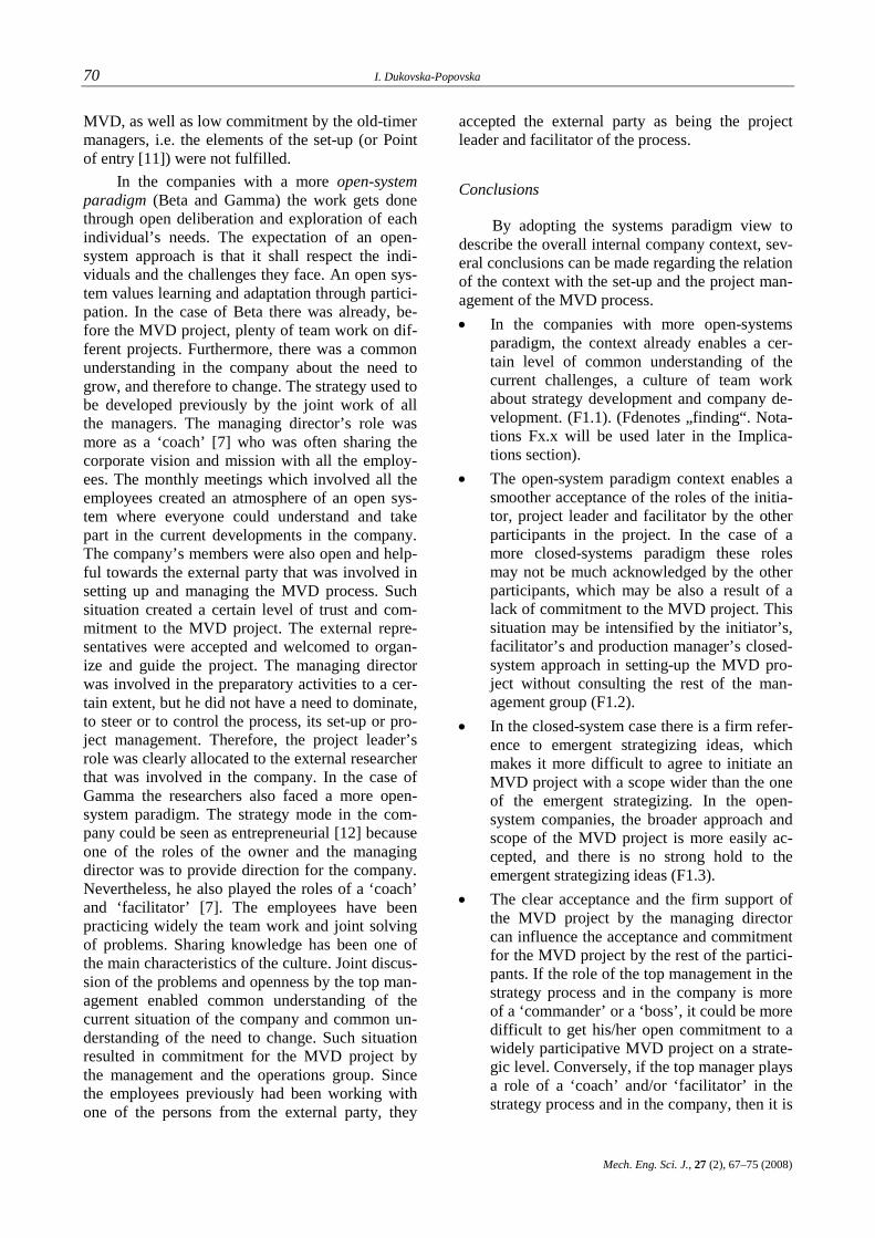
A hundred years ago the crutch was revolu-tion; today it is the microprocessor controlled pros-thesis (Fig. 16). What about tomorrow?
3D digitalization in orthopedics 65
Ma{. in`. nau~. spis., 27 (2), 59‡63 (2008)
Fig. 16. Modern prosthesis
REFERENCES
[1] Brncick M.: Computer automated design and computer automated manufacture, Department of Physical Medi-cine and Rehabilitation, Northwestern University, Chi-cago, Illinois, USA, 2002.
[2] Training tutorial ATOS II, 2007. [3] Tutorial Solid Works, 2007.
[4] Sankar Wudblav N., Brekston Josh A., Lerman Lawrence, Tolo Vernon T., Sklaggs David L.: Scoliosis in-brace curve correction and patient preference of CAD/CAM versus plaster molded TLSOs, 2007.
[5] SmithD. G., BurgessE. M.: The use of CAD/CAM technol-ogy in prosthetics and orthotics – current clinical models and a view to the future, University of Washington, Pros-thetics Research Study, Seattle 98104, USA 2001.
R e z i m e
3D DIGITALIZACIJA VO ORTOPEDIJATA
Jasmina ^aloska1, Davor Karaka{ev1, Atanas Ko~ov1, Bor~e Stojkov2
1Ma{inski fakultet, Univerzitet „Sv. Kiril i Metodij“, p. fah 464, MK-1001 Skopje, Republika Makedonija
2Ortopedski zavod SLAVEJ AD, Skopje, Vasil \orgov br.45 , 1000 Skopje, Republika Makedonija
Klu~ni zborovi: digitalizacija; ortopedski pomagala; tehnologija CAD
Denes, vo ritamot na sovremenoto `iveewe, pro-blemot na invaliditet stanuva se po~est ograni~u-va~ki faktor za normalno funkcionirawe na ~ove-kot. Napredokot na tehnologijata i elektronikata ovozmo`uva sekojdnevno podobruvawe na uslovite za rabota i `ivot na licata so hendikep.
Vo ovoj trud stanuva zbor za primenata na sovre-menite tehniki i tehnologii vo ortopedijata, kako i za dostignuvawata vo ovaa oblast i nasokite vo koi taa se razviva. Poseben osvrt e daden na 3D digi-talizacija vo slednive nasoki: 3D digitalizacija i modernizacija vo izrabotka na ortopedski pomagala.

Mechanical Engineering – Scientific Journal, Vol. 27, No. 2, pp. 67–75 (2008) CODEN: MINSC5 – 395 ISSN 1857–5293 Received: August 19, 2008 UDK: 005.8(489) Accepted: October 2, 2008 005.8(497)
Original scientific paper
CONSIDERING THE CONTEXT, SETUP, PROJECT MANAGEMENT AND DIALOGUE IN MANUFACTURING VISION DEVELOPMENT PROCESSES
Iskra Dukovska-Popovska
Department of Production, Aalborg University, Fibigerstraede 16, 9000 Aalborg, Denmark
A b s t r a c t: This paper discusses the relationship be-tween the internal company context, setup, the project man-agement and the dialogue of the process of Manufacturing Vision Development (MVD), a process that enables compa-nies to develop their future manufacturing concept. The pre-sented research is a part of a broader research project, aiming to understand the process of developing manufacturing visions and strategies, looking from a dialogue perspective. The paper elaborates how the main process elements affect each other and the outcome, and draws implications for future planning and facilitation of such processes.
Key words: manufacturing vision development; process; dialogue; participants
1. INTRODUCTION AND BACKGROUND
In the reality of dynamic changes and com-plex environments, industrial companies need to undertake initiatives in order to survive and to achieve success. Many studies have argued that manufacturing plays an important role in the com-pany dealing with its market and competitive envi-ronment [1], [2], [3]. The potential of manufactur-ing becomes even larger if we see manufacturing as part of an extended enterprise, continuously in-teracting with the other functions.
Having in mind such a scenery companies, more than ever, need to have a manufacturing vi-sion – a concept of how their manufacturing will look like in the future 5 years [3]. Building such a concept has to consider the current and the future environmental, technological and market chal-lenges. Moreover, its successful implementation will be more likely if the process of manufacturing vision development (MVD) involves the actors who will implement the vision, triggers their crea-
tivity, and leads to an integrated solution, which inspires the actors to implement it [3]. The actors will most likely come from each of the company functions and from different hierarchical levels. However, getting people to work together can be difficult because they bring along their functional knowledge, cultures and assumptions. Schein [4] explains that to create alignment among subcul-tures is not a matter of deciding which one has the right viewpoint, but of creating enough mutual un-derstanding among them to develop solutions that are understood and will be implemented. This view coincides with the idea of dialogue as a flow of meaning in the whole group, out of which may emerge a new understanding which may not have existed at the starting point [5]. Consequently, by nurturing dialogue, the group can build a shared vision, based on mutual understanding and creativity.
The previous research on the manufacturing vision and strategy development hasn’t considered the participants perspective. Because of the obvi-ous importance of the participants and their dia-logue in this process, as briefly explained above, we devoted our research on the participants and dialogue perspective of the MVD process [9].
2. THEORETICAL MODEL
At this point, it is clear that our research is fo-cusing on the process (or the „how“) and the par-ticipants aspects of the MVD. As a starting point of this research, we explored the process models and process aspects in the existing strategy develop-ment literature (for example, [7], [11], [15]). This

68 I. Dukovska-Popovska
Mech. Eng. Sci. J., 27 (2), 67–75 (2008)
TIME
Internal context
External context
Emergent strategizing
MANUFACTURING VISION DEVELOPMENT PROCESS
Internal context
External context
Emergent strategizing
Set up
Project management
Activities/
Participants
Content
OutcomesCONTEXT
CONTEXT
DIALOGUE PROCESS
explorative research enabled us to create a model of the overall MVD process (Fig. 1) [6]. Such a model is used later in the observations and analy-ses of MVD processes in the case companies.
The main process elements identified from the literature are the context, the setup, the project management, the vision development (dialogue) process, and the outcomes (Fig. 1). The literature offers different operationalizations of these ele-ments [7]. For example, the context is seen as the structural, cultural and political situation of the company. However, most of the context elements pinpointed in the literature do not refer explicitly to the formulation/development process but rather to the overall strategy process. Furthermore, activities of the process itself that have been identified in the literature are generating information, analyzing information, identifying improvements. The par-ticipants in the process have only been observed through the lens of being internal or external to the company, and the function to which they belong. The existing operationalizations of these elements are at a higher, organizational level, and do not help much understanding the dynamics of the process at the participant level, and do not offer suggestions for facilitating MVD processes. There-fore, we see the need to operationalize these ele-ments in the context of MVD (briefly described in Section 1) and at participant level. Some more spe-cific context elements appeared to influence the
set-up and the project management of the MVD process, such as interdepartmental relations, com-pany culture, strategy development practices, dif-fering orientations, company communication and collaboration culture, as well as the learning cul-ture [6]. Furthermore, the setup and the project management need to be considered through the trigger of the process, the initiator, the focus/scope of the project, the project manager and task groups. The development process itself needs to be ob-served through the main activities at the workshops (presentations, idea gathering discussions, group work) as well as dialogic activities of the participants (advocating, judging, inquiring, reflecting, listening).
Furthermore, based on the work and assump-tions of Pettigrew [8], the processual analysis should consider the what, why and how of the links between context, process and outcomes. In addi-tion, Pettigrew [8] notes that in processes, the in-terchange between actors and contexts occurs over time and is cumulative. To our knowledge, there is no research done on the what, why and how of the relationship between the process elements in the MVD context. Therefore we decide to explore what are the elements of the process, why they oc-cur, and how they interact with each other. The current paper focuses on the interrelation between the context, the setup, the project management and the dialogue, as the key elements of the process of MVD.
Fig. 1. A model of the overall MVD process
3. RESEARCH METHODOLOGY
The research involved case studies of three companies, two Danish and one Balkan company (Tab. 1), and focused on the initial phases of the MVD process. We used the following methods for data collection and analysis:
• Direct observations of the meetings and workshops in connection to MVD.
• Video-recording of the workshops. • Identification, transcription and, in the case
of the Danish companies, translation of im-portant segments.
• Interviews with the company participants.

Considering the context, setup, project management and dialogue in manufacturing vision development processes 69
Ma{. in`. nau~. spis., 27 (2), 67‡75 (2008)
T a b l e 1
Manufacturing vision development in the three case companies Alpha Beta Gamma
Workshop 1 Identifying future trends and challenges. Identifying elements of the vision.
Creating a common understanding of the current way of working. Identifying current problems in the order fulfillment process. Outline elements of the vision.
Identifying future trends and chal-lenges. Outlining problems in the current way of working.
Workshop 2 Developing scenarios for the future vision
Creating common understanding of trends and future challenges. Identifying core competences. Developing scenarios for the future vision.
Identifying elements of the future vision and developing general ideas for their implementation.
4. ANALYSIS AND FINDINGS
4.1. The relationship between the internal context of the company with the set-up and project
management of the MVD process
General context elements for manufacturing strategy development have been pointed out in the literature [6], [7]. However, some more specific context elements appeared to influence the set-up and the project management of the MVD process, such as interdepartmental relations, company cul-ture, strategy development practices, differing ori-entations, company communication and collabora-tion culture, as well as learning culture [6]. Now, the relationships between the context, the process set-up and project management across the case studies will be elaborated in this section.
The concept of ‘system paradigms’ by David Kantor [10] appears appropriate to explain the dif-ferent contexts observed in the cases and therefore it is further applied in the cross-case analysis. Sys-tem paradigms represent different ways of setting boundaries to the external parties, governing, and organizing power and decision making in the com-panies. Since the MVD process in all three compa-nies was initiated in collaboration with a party ex-ternal to the company, the behavior of the com-pany participants towards the external party as well as inside the company can be explained by the sys-tem paradigms concept.
The Alpha company, can be seen more as a closed system. One of the characteristics of a closed-system paradigm is to refine and defend the history, to place community and history first and the individual second [10]. A closed system regu-lates the life of its members, particularly the time and space within which people work. In the case of
Alpha ‘history’ was expressed through stressing a common platform that old-timer managers shared about the company and about how the things are done in the company. They stressed several times at the workshops that the newcomer managers first had to understand the well-established ways of working and values, and refused to accept the emergent possibilities that were coming from the initiators of the MVD project (the newcomers). The managing director tended to control most of the decisions in the company, and he was involved in discussing problems on different levels with each of the departments separately. He did not ini-tiate collaborative cross-functional activities, such as joint management meetings or joint strategy de-velopment. He could be seen playing the roles of a ‘commander’ or a ‘boss’ [7] in the company strat-egy process. On the other hand, the production manager (a newcomer in the company) behaved in a sort of closed-system paradigm as well. He was guided by a previous success in MVD in another company and was convinced that it is the right way to initiate change in Alpha, without being open enough to share his background and the idea for the process with the old-timer managers. He also paired with the other newcomer manager (the mar-keting manager). This separation (differing orienta-tions) between the newcomers and old-timers as a contextual situation in the company resulted in a lack of a common view on the need for changes in the company. Furthermore, the company culture regarding induction of new employees as well as the communication culture made the newcomers setup the MVD process by themselves, without consulting the old-timer managers. They were also supposed to carry the project leader role during the whole process. This resulted in low common un-derstanding and agreement about the process of
70 I. Dukovska-Popovska
Mech. Eng. Sci. J., 27 (2), 67–75 (2008)
MVD, as well as low commitment by the old-timer managers, i.e. the elements of the set-up (or Point of entry [11]) were not fulfilled.
In the companies with a more open-system paradigm (Beta and Gamma) the work gets done through open deliberation and exploration of each individual’s needs. The expectation of an open-system approach is that it shall respect the indi-viduals and the challenges they face. An open sys-tem values learning and adaptation through partici-pation. In the case of Beta there was already, be-fore the MVD project, plenty of team work on dif-ferent projects. Furthermore, there was a common understanding in the company about the need to grow, and therefore to change. The strategy used to be developed previously by the joint work of all the managers. The managing director’s role was more as a ‘coach’ [7] who was often sharing the corporate vision and mission with all the employ-ees. The monthly meetings which involved all the employees created an atmosphere of an open sys-tem where everyone could understand and take part in the current developments in the company. The company’s members were also open and help-ful towards the external party that was involved in setting up and managing the MVD process. Such situation created a certain level of trust and com-mitment to the MVD project. The external repre-sentatives were accepted and welcomed to organ-ize and guide the project. The managing director was involved in the preparatory activities to a cer-tain extent, but he did not have a need to dominate, to steer or to control the process, its set-up or pro-ject management. Therefore, the project leader’s role was clearly allocated to the external researcher that was involved in the company. In the case of Gamma the researchers also faced a more open-system paradigm. The strategy mode in the com-pany could be seen as entrepreneurial [12] because one of the roles of the owner and the managing director was to provide direction for the company. Nevertheless, he also played the roles of a ‘coach’ and ‘facilitator’ [7]. The employees have been practicing widely the team work and joint solving of problems. Sharing knowledge has been one of the main characteristics of the culture. Joint discus-sion of the problems and openness by the top man-agement enabled common understanding of the current situation of the company and common un-derstanding of the need to change. Such situation resulted in commitment for the MVD project by the management and the operations group. Since the employees previously had been working with one of the persons from the external party, they
accepted the external party as being the project leader and facilitator of the process.
Conclusions
By adopting the systems paradigm view to describe the overall internal company context, sev-eral conclusions can be made regarding the relation of the context with the set-up and the project man-agement of the MVD process. • In the companies with more open-systems
paradigm, the context already enables a cer-tain level of common understanding of the current challenges, a culture of team work about strategy development and company de-velopment. (F1.1). (Fdenotes „finding“. Nota-tions Fx.x will be used later in the Implica-tions section).
• The open-system paradigm context enables a smoother acceptance of the roles of the initia-tor, project leader and facilitator by the other participants in the project. In the case of a more closed-systems paradigm these roles may not be much acknowledged by the other participants, which may be also a result of a lack of commitment to the MVD project. This situation may be intensified by the initiator’s, facilitator’s and production manager’s closed-system approach in setting-up the MVD pro-ject without consulting the rest of the man-agement group (F1.2).
• In the closed-system case there is a firm refer-ence to emergent strategizing ideas, which makes it more difficult to agree to initiate an MVD project with a scope wider than the one of the emergent strategizing. In the open-system companies, the broader approach and scope of the MVD project is more easily ac-cepted, and there is no strong hold to the emergent strategizing ideas (F1.3).
• The clear acceptance and the firm support of the MVD project by the managing director can influence the acceptance and commitment for the MVD project by the rest of the partici-pants. If the role of the top management in the strategy process and in the company is more of a ‘commander’ or a ‘boss’, it could be more difficult to get his/her open commitment to a widely participative MVD project on a strate-gic level. Conversely, if the top manager plays a role of a ‘coach’ and/or ‘facilitator’ in the strategy process and in the company, then it is

Considering the context, setup, project management and dialogue in manufacturing vision development processes 71
Ma{. in`. nau~. spis., 27 (2), 67‡75 (2008)
easier to get her/his open commitment for the widely participative MVD project (F1.4).
• Some recent events can hinder the set-up and the project management of the MVD process to a certain degree. The presence of the new-comer and old-timer managers may delay or prevent from acquiring the common under-standing, agreement and commitment about an MVD project. Unforeseen events may pre-vent the attendance to already planned work-shops by certain participants. Recent business contracts may limit the scope of the project. However, in the companies characterized by a more closed-system paradigm, such recent events may persist, while in the companies with more open-system paradigm the facilita-tor may guide the process so that he/she over-comes the effects of the recent events (F1.5). It has been stated at the beginning of this sec-
tion that the concept of system paradigms may ex-plain the context of the company in relation to the MVD process. The analysis made in this section as well as the conclusions drawn, validates the appro-priateness of the concept. Therefore the concept of system paradigms should be added in the model of the overall MVD process as a specific feature of the internal company context.
4.2. Relationships between the context, he set-up and the project management,
and the conversational dialogue process
It could be observed that the dialogue differed in all three cases, as well as between the two dif-ferent workshops in one case. It has been recog-nized in the literature [10], [13] that every dialogue takes place in the context of and is steered by the formal, interpersonal, and cultural structures. Since the dialogue has been identified to play an impor-tant role in the MVD process, this section focuses on the relationship between the context, the set-up and the project management on the one hand, and the dialogue on the other hand. It has been ob-served that the least constructive dialogue process was featured in the first workshops of the Alpha and Beta cases. The rest of the workshops showed higher quality of the dialogue process. How can these differences be explained from a perspective of organizational context, the MVD set-up and the project management?
A dialogue at a level of debate was mostly evident during the first workshop of the Alpha case, and partly at the first workshop of the Beta
case. In the Alpha case the conflicts emerged and pertained during the whole workshop between the newcomer and the old-timer managers of the com-pany. The newcomers tried to propose some new directions for the future production of the com-pany, while the old-timers tried to defend the cur-rent situation. During the dialogue there was no reflection on what people said, there was mostly judgment on each others ideas. The inquiry was conducted not in order to understand better the others perspective, but to judge it and advocate one’s own perspective. The newcomers and the old-timers between themselves interchanged the roles of a mover and an opposer, while inside their ‘coalitions’ the roles of a mover and a follower. Some of the causes for these situations can be found in the set-up of the MVD project, but those causes were amplified by the organization’s con-text. The relationship of the context with the set up was already elaborated in the previous section and will not be repeated here. The initiator of the pro-ject in Alpha (one of the newcomers), during the planning of the workshop, discussed the ideas and the directions for the new production only with the other newcomer. At the workshop they openly voiced their prior agreement on the issues, and they tried to advocate those issues through the whole workshop. This upset the old-timers, and they believed that the newcomers should learn bet-ter the current way of working in the company be-fore making conclusions about it and proposing ideas about how to improve it. The next cause for the conflicting atmosphere at the workshop can be seen in the level of understanding, agreement and commitment of the managing group with the MVD project. Except for the managing director, none of the other functional managers was involved in building agreement and common understanding about the need for MVD. It can be said that the problems in the production were evident to every-body in the company. Nevertheless that did not bring people to a common view of the need to change. The old-timers saw the solution in building new capacities, while the newcomers saw it in changing some practices in the current way of working. It was evident that the managing group needed more time to create a common understand-ing about the MVD project, and therefore, the dia-logue at the first workshop suffered. However, dur-ing this workshop the management group realized that they had to work on improving their mutual relationships and on acquiring a common under-standing of the current trends, the company chal-lenges and the need to change. The workshop, in
72 I. Dukovska-Popovska
Mech. Eng. Sci. J., 27 (2), 67–75 (2008)
fact, initiated joint management meetings to be held regularly in the future, as well as a socializing event that will improve the collaboration and the dialogue between the newcomers and the old-timers.
In the Beta case the conflict emerged between the sales and the engineering managers, and it was harmonized but not resolved. Both sides advocated their perspectives and did not reflect much nor in-quired into each others perspective. A negative influence of the set-up on the dialogue in the first workshop of Beta has not been found. The initiator of the project was an external party, but he worked closely with the other managers and especially with the managing director. In fact there was no debate that could prevent the MVD project itself. The same was the case in the other workshops. In the case of Gamma the external party created a common understanding about the project with the company owner who shared his enthusiasm for the project with the rest of the participants. Therefore, the participants in the Gamma case focused more on reflecting on the proposed issues as well as in-quiring into the perspectives, which led to creating new meanings and a more constructive dialogue.
Furthermore, some causes for the low-quality dialogue can be rooted in the project management. The role of the facilitator in Alpha was overtaken by the initiator of the project. Also, external par-ticipants were involved to help the facilitation, but the initiator had the dominant role. Since the facili-tator strongly held on to his initial ideas about the direction of the workshop, it resulted in him judg-ing other participants’ ways of thinking, if they did not comply with his perspective. This resulted in him either opposing participants’ views or moving the dialogue in the direction he wanted. The other two facilitators did not play a big role during the workshop and their initiatives were also not much accepted by the old-timers. In the case of Beta the role of the facilitator was clearly played by the ex-ternal participants and it was accepted by the com-pany participants. During the period of debate the facilitator tried to bystand and to propose a differ-ent view that could bring the conflicting sides to see beyond the conflict. Nevertheless, they did not reflect at all on what had been proposed. This can be explained to a certain degree by the internal context of the company. Although Beta has been seen as an open-system paradigm company, there is still some closed-system behavior between the departments, especially between the sales depart-ment and the rest of the departments. During the
other workshops, the facilitator role was clearly played by an external person and it was accepted by all participants. In those situations the facilitator played the role of a bystander, or a mover, trying to guide the dialogue in the direction of achieving the aims of the workshop. He was also the one who inquired in order to guide the dialogue.
One of the context factors that influenced the dialogue in Alpha directly was the closed-system paradigm of the company and of the newcomers. Furthermore, the managing director’s prior deci-sion of building a new plant and his orientation towards discussing more operational level issues prevented most of the discussions at a strategic level. This explains why the role that the managing director played at the workshop was one of a pas-sive observer, one of praising or advocating the current way of working. The more open-system paradigm in the other companies enabled a higher quality dialogue at the workshops. First, it enabled participants to have a better common understand-ing of the need to change and to accept easily the MVD project. Second, the managing director (or the owner in Gamma) was very open and suppor-tive during the workshops. He genuinely shared some general principles and visions about the company, and did not try to limit the discussion.
Conclusions
The previous elaborations imply the follow-ing generic conclusions. • Existing conflicting perspectives in the com-
pany (cross-functional or between newcomers and old-timers) may be a source for debate during the MVD process. In the case of the closed-system paradigm such a debate may block the whole workshop and dominate the whole dialogue. However, in the case of the open-system paradigm the debate may be by-passed and a more constructive dialogue may be initiated on different issues. In both cases this debate may be a stimulus for a group (or organizational) learning that may evolve after the workshop (F2.1).
• If the managing director (or the highest au-thority) in the company does not show explicit support and understanding for the process of manufacturing vision development, or if she/he is inclined too much toward the opera-tional and day-to-day improvements, it will cause problems in the development of the dia-logue on a strategic level (F2.2).

Considering the context, setup, project management and dialogue in manufacturing vision development processes 73
Ma{. in`. nau~. spis., 27 (2), 67‡75 (2008)
• If the initiation of the MVD project is done by a narrow participation from the management group, not representing different orientations existing in the company, then a debate is likely to occur between the initiators and the invitees, thereby preventing the building of common understanding of the need to change and of the MVD process (F2.3).
• If the facilitator (internal or external) favors certain solutions, and if he/she initiated the MVD process without consulting the whole management group, then the facilitator may be largely perceived as a dominant person. This increases the probability that the others will not reflect on the initiatives, but only make judgments and advocate other perspec-tives (F2.4).
• If in an MVD process the facilitator role is played by an external participant, then it can lead to a constructive dialogue on the strategic issues of MV. In a company with newcomers in a management position, an external facilita-tor may be a better choice instead of facilita-tion by the newcomers, especially in a context of a closed system paradigm (F2.5)
5. IMPLICATIONS
In relation to the findings in the previous two sub-sections (4.1 and 4.2) the following implica-tions for the future design of an MVD project have been drawn, having in mind the relationship be-tween the context, the set-up and the project man-agement, and the dialogue. NB: Each implication is written in a paragraph that is marked by the find-ing to which the implication refers to. • (F1.2, F1.3) To a certain degree, the closed
system paradigm presents a hindering context for the MVD process. The top manager, who usually plays the role of the ‘commander’ or ‘boss’, may not easily agree on a widely par-ticipative process at a strategic level. In addi-tion, a commitment about the MVD process with a wider scope may be more difficult to achieve. The roles of the initiator, facilitator and project manager may not be well ac-knowledged in such a context. The first thing to do is to identify if the company operates under a closed-system paradigm. An impor-tant thing is not to try to change the com-pany’s way of thinking and not to try to make them conform to the facilitator’s (initiator’s)
way of thinking, but to spend more time on trying to understand how they are working and why they are working in that way. In this situation the initiator (facilitator) of the pro-ject needs to have a more listening attitude. He/she may practice behaviours which may enable active listening. One such behaviour is ‘reflecting the implications’ – going beyond the content expressed by somebody and build-ing on or extending the ideas [14]. Reflection of the implications should be used to help the speaker understand his/her thinking, and at the same time leaves the speaker in control of the conversation, instead of showing to him/her as being more clever by changing the direction of thinking. This method seems appropriate to extend the ideas of the top management (or company representative). It will hopefully lead to the company opening itself and par-ticipating in a dialogue about MVD. After this approach, if the top management (or company participant(s)) refuses to be open and partici-pate, as a result of mistrust, then the initiator may choose to leave the MVD project. How-ever, one should also be aware that it makes very little sense to encourage a closed-system manager to adopt wholeheartedly an open-system approach [10]. But the person’s para-digm can be respected and understood, and this can enable a very different way of think-ing together [10].
• (F1.3) It can also happen that the emergent strategizing may be a dominating view of the participants. In fact, the emergent strategizing issues need to be considered during the set-up phase since they reflect the current strategic issues, emergent aspirations and taken-for-granted beliefs in the company [15]. However, this can be an undesirable situation if the emergent strategizing leads to a narrow scope or narrow approach to the existing problem or to the current situation. In that case it can pre-vent the initiation of a dialogue aimed at ex-ploring some other possibilities or approaches to the problem. It seems that a special point-of-entry should be initiated, through which, a dialogue is developed between the facilitator (the initiator), and the management group in order to explore jointly other possibilities for development in the company. The strategic concerns of each manager need to be consid-ered either through individual interviews or at a joint meeting, and should be included in planning the scope and the initial ideas about

74 I. Dukovska-Popovska
Mech. Eng. Sci. J., 27 (2), 67–75 (2008)
the MV. In this situation the set-up has to in-corporate some tools to broaden the view of the participants. The use of strategic frame-works such as Hill’s order winner and order qualifier criteria, and Fine’s 3-D Concurrent Engineering framework may enable partici-pants to open their mind and include new di-mensions and new solutions [16]. The partici-pants should be guided towards divergent conversation by inquiring more at a strategic level, for example by asking: ‘How may you sustain or improve the advantage in the high end (or other) segment of the market?’, ‘What ideas do you have on how you might go after other segments?’, etc. The atmosphere or be-lief of having the right answer needs to be re-placed with an atmosphere of reflection [17] where the participants may have an opportu-nity to relate new information to what is al-ready known and thus possibly acquire a new perception.
• (F1.5) Part of the set-up phase should be used to discover the recent events that may impact the MVD project. It should be anticipated in which way these events may influence the project, i.e. its content, its dialogue, its par-ticipation. Some of these events may be used as an opportunity for group (or organizational) learning and special preparation may be un-dertaken to develop the learning. For example, if the company faces a new business agree-ment and consequently it needs to develop its production in order to respond appropriately, the new development may be directed not solely to the new requirements but to the overall trends and challenges in the area. Thus, an intervention for broadening the scope needs to be planned at the set-up of the workshop. The guidelines given in the previ-ous paragraph may well apply in this situa-tion.
• (F2.4, F2.5) The project management needs to carefully consider the choice and the role of the facilitator. If an internal facilitator is being considered, then a care should be taken so that he or she does not favour only his/hers per-sonal views/ideas. A phase in the MVD proc-ess has to be involved where the views and the ideas of other managers about company’s strategic development are considered. The last suggestion is probably a task which appears more necessary to the external facilitator, but the internal facilitator as well needs to under-
take it explicitly. The dialogic roles that the facilitator needs to play mostly are the one of bystander, in order to offer an overview of what is happening in the dialogue, as well as the one of mover (through inquiry and reflec-tion), in order to guide the dialogue and the work in the workshop. In order for the facili-tator not to be perceived as a dominant person he/she needs to call for open participation, be an active listener to what participants are say-ing, show interest, and tackle issues that are of key interest for the company and the partici-pants.
• (F2.1, F2.3) Differing orientations (or con-flicting perspectives) already existing in the company have been seen as points for debate and conflicts during MVD process. Therefore, representatives from all parties should be in-cluded in the planning stage of the MVD process in order to prevent difficulties in building common understanding about the need for MVD. Furthermore, the set-up has to consider developing an understanding about the different perspectives by inquiring into the main assumptions. This will possibly prevent unproductive discussions that may arise espe-cially in a closed-system paradigm company. On the other hand, the conflicting perspec-tives may be used as an opportunity for learn-ing and creativity if a dialogue is developed. Ellinor and Gerard [17] propose two tactics that can support the development of a dia-logue. Firstly, the focus needs to be placed on the role rather than on a specific individual. In that way it becomes safer for people to talk about what is important. If the conflict is per-sonalized, it is more difficult to speak openly. Secondly, the polarities can be used to gain clarity, flash a larger picture, and discover al-ternatives. To achieve this aim, the first thing to be done is to identify the polarities. After-ward, participants need to be encouraged to speak from both roles, i.e. each person will take both sides. The result of this could be an enhanced understanding as well as creative al-ternative ways of working with an issue.
• The organizational context can not be ex-pected to be changed in such a short time frame. However, the possible influences from the context may be included in the set-up, the project management and the design of the MVD process. Furthermore, it may be ex-pected that the initial phases of the MVD

Considering the context, setup, project management and dialogue in manufacturing vision development processes 75
Ma{. in`. nau~. spis., 27 (2), 67‡75 (2008)
process may influence the context to a certain degree thereby enabling a better dialogue and better process later in the MVD consequently leading to an organizational (as well as group and individual) learning.
REFERENCES
[1] Skinner W.: Manufacturing – the missing link in corporate strategy, Harvard Business Review, 47, 3, 136–145 (1969).
[2] Hill T. J.: Incorporating manufacturing perspectives in corporate strategy. In Manufacturing strategy: Process and content, C. A. Voss, ed. Chapman & Hall, London, 1992, pp. 3–12.
[3] Riis J. O., Johansen J.: Developing a manufacturing vi-sion, Production Planning and Control, 14, 4, 327–337 (2003).
[4] Schein E. H.: The three cultures of management: Implica-tions for organizational learning, Sloan Management Re-view, 38, 1, 9–20 (1996).
[5] Bohm D.: On dialogue, Routledge, London, 1996. [6] Dukovska-Popovska I.: Development of Manufacturing
Vision – Process and Dialogue, PhD Thesis, Center for Industrial Production, Aalborg University, Aalborg, 2006.
[7] Mills J., Platts K., Gregory M. J.: A framework for the design of manufacturing strategy process: A contingency approach. International Journal of Operations & Produc-tion Management, 15, 4, 17–49 (1995).
[8] Pettigrew A. M.: What is a processual analysis? Scandi-navian Journal of Management, 13, 4, 337–348 (1997).
[9] Riis J. O., Dukovska-Popovska I., Johansen J.: Participa-tion and dialogue in strategic manufacturing develop-ment, Production Planning & Control, 17, 2, 176–188, (2006).
[10] Isaacs W.: Dialogue and the art of thinking together, Currency, New York, 1999.
[11] Platts K.: Characteristics of methodologies for manufac-turing strategy formulation, Computer Integrated Manu-facturing Systems, 7, 2, 93–99 (1994).
[12] Mintzberg H.: Strategy making in three modes. Califor-nia Management Review, 16, 2, 44–53 (1973).
[13] Smith D. M.: Keeping a strategic dialogue moving. 1995, Retrieved August, 15, 2008, from
http://www.actiondesign.com/resources/theory/ksdm.htm [14] Osland J. S., Kolb D. A., Rubin I. M.: Organizational
behavior: An experiential approach, Prentice Hall, New Jersey, 2001.
[15] Eden C., Ackermann F.: Making strategy: The journey of strategic management, SAGE Publications, London, 2002.
[16] Riis J. O., Joergensen H.: Time out: Means for initiating a strategic development process for operations. In Proceed-ings of the 4th International CINet Conference, Continu-ous Innovation in Business Processes and Networks, R. Smeds ed., Helsinki University of Technology, Espoo, 2002, pp. 565–578.
[17] Ellinor L., Gerard G.: Dialogue: Rediscover the trans-forming power of conversation, John Wiley & Sons, Inc, New York, 1998.
R e z i m e
KONTEKST, PODGOTOVKA, PROEKTEN MENAXMENT, I DIJALOG VO PROCESOT NA RAZVOJ NA PROIZVODSTVENA VIZIJA
Iskra Dukovska-Popovska
Department of Production, Aalborg University Fibigerstraede 16, 9220 Alborg Oest, Danska
Klu~ni zborovi: proizvodstvena vizija; proces; dijalog; kontekst
Vo ovoj trud se diskutira me|usebnoto vlijanie pome|u vnatre{niot kontekst na kompanijata, podgo-tovkata, proektniot menaxment i dijalogot vo proce-sot na razvoj na proizvodstvena vizija ‡ proces koj ovozmo`uva kreirawe na koncept za idnoto proizvod-stvo na kompanijata. Istra`uvawata se del od po{i-rok istra`uva~ki proekt, koj ima za cel da go razbere
procesot na razvoj na proizvodstvena vizija i strate-gija, gledaj}i go od perspektiva na u~esnicite vo pro-cesot i nivniot dijalog. Trudot elaborira kako glav-nite elementi na procesot vlijaat eden na drug i iz-vlekuva nasoki za idno planirawe i moderirawe na takvi procesi.
Mechanical Engineering – Scientific Journal, Vol. 27, No. 2, pp. 77–95 (2008) CODEN: MINSC5 – 396 ISSN 1857–5293 Received: September 29, 2008 UDK: 656.7.082.001.573 Accepted: October 8, 2008
Original scientific paper
APPLICATION OF EXPERT SYSTEMS TO AIRCRAFT ACCIDENT INVESTIGATION
Goran Milošovski1, Cees Bil1, Milan Ćosevski2 1School of Aerospace, Mechanical and Manufacturing Engineering, RMIT University,
Melbourne, Australia 2Faculty of Mechanical Engineering, ”SS. Cyril and Methodius” University,
P.O. Box 464, 1000 Skopje, Republic of Macedonia [email protected] // [email protected]
A b s t r a c t: In the last few decades there has been a considerable growth in the development of scientific method-ologies for investigating complex issues, such as aircraft acci-dents, in order to establish a set of priorities for significant improvement that are possible and desired. The essence of these methodologies is providing the optimal decision with respect to these priorities, which is based on information available, the strategic objectives and prediction of the future condition of issues to be considered. An interdisciplinary ap-proach and intuition have shown to be vital elements in devel-oping contemporary methods for creating strategic decisions. A number of intuitive methods have been developed over the past few decades. One of the most successful among these methods is the Delphi technique. This paper points out the Delphi conclusions with respect to improvement of aircraft accident investigation. That is to say, the paper points out the spots and stages of aircraft accident investigation where sig-nificant improvements can be made by employment of con-temporary technology and science. Moreover, this paper pro-vides a qualitative and quantitative analysis of influential fac-tors that have an impact on investigation outcomes. Further-more, this paper addresses the need for a tool, which will be able to include and contain specific knowledge, and the ana-lytical skills of a large number of experts. Finally, this paper discusses and concludes that aircraft accident investigation could be improved with the application of a global expert sys-tem as a tool for storing and analysing the forensic data of aircraft accidents worldwide.
Key words: expert systems; Delphi method; aircraft accident investigation
1. INTRODUCTION
The investigation of aircraft accidents is fo-cused on the circumstances of the accident includ-ing gathering, recording and analysis of all avail-able information, and the drawing of conclusions, including the determination of accident causes [5].
Furthermore, since the sole objective of the inves-tigation of an accident is the enhancement of air traffic safety, the investigative team, when appro-priate, based on information derived from the in-vestigation, can introduce recommendations with the intention of preventing future accidents (and incidents).
The investigation of a massive aircraft acci-dent engages a number of different staff, special-ists, experts, legal authorities, accredited represen-tatives, representatives originating from the state of design, manufacture, operator, and so on, conducting a certain portion of aircraft accident investigation.
Thus, in order to determine the causes for the accident, investigators need to pursue comprehen-sive examinations of the accident site, wreckage, witness information, recorded media, component examinations, tests, simulations, and so on. This indicates that an aircraft accident investigation is a complex issue affected by many factors of differ-ent natures. As a result, these questions, how the aircraft accident investigation can be suitably con-sidered and what methods can be applied to further improve the aircraft accident investigation process, emerged.
2. THEORY OF MAKING STRATEGIC DECISIONS AND FORECASTING – THEORY
OF INTUITIVE METHODS
According to Dobrov [2] there are more than 130 different methods for creating scientific deci-sions. He divided these methods into three basic
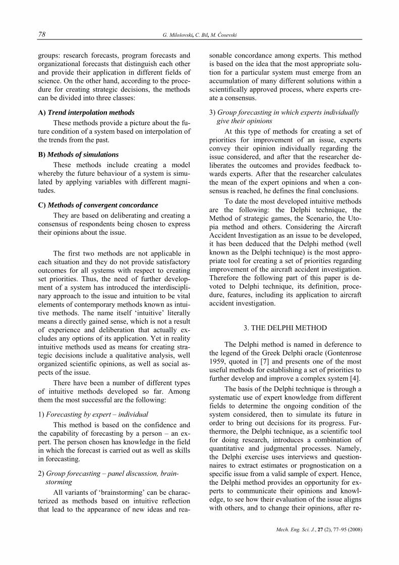
78 G. Milošovski, C. Bil, M. Ćosevski
Mech. Eng. Sci. J., 27 (2), 77–95 (2008)
groups: research forecasts, program forecasts and organizational forecasts that distinguish each other and provide their application in different fields of science. On the other hand, according to the proce-dure for creating strategic decisions, the methods can be divided into three classes:
A) Trend interpolation methods These methods provide a picture about the fu-
ture condition of a system based on interpolation of the trends from the past.
B) Methods of simulations These methods include creating a model
whereby the future behaviour of a system is simu-lated by applying variables with different magni-tudes.
C) Methods of convergent concordance They are based on deliberating and creating a
consensus of respondents being chosen to express their opinions about the issue.
The first two methods are not applicable in
each situation and they do not provide satisfactory outcomes for all systems with respect to creating set priorities. Thus, the need of further develop-ment of a system has introduced the interdiscipli-nary approach to the issue and intuition to be vital elements of contemporary methods known as intui-tive methods. The name itself ‘intuitive’ literally means a directly gained sense, which is not a result of experience and deliberation that actually ex-cludes any options of its application. Yet in reality intuitive methods used as means for creating stra-tegic decisions include a qualitative analysis, well organized scientific opinions, as well as social as-pects of the issue.
There have been a number of different types of intuitive methods developed so far. Among them the most successful are the following:
1) Forecasting by expert – individual This method is based on the confidence and
the capability of forecasting by a person – an ex-pert. The person chosen has knowledge in the field in which the forecast is carried out as well as skills in forecasting.
2) Group forecasting – panel discussion, brain-storming
All variants of ‘brainstorming’ can be charac-terized as methods based on intuitive reflection that lead to the appearance of new ideas and rea-
sonable concordance among experts. This method is based on the idea that the most appropriate solu-tion for a particular system must emerge from an accumulation of many different solutions within a scientifically approved process, where experts cre-ate a consensus.
3) Group forecasting in which experts individually give their opinions
At this type of methods for creating a set of priorities for improvement of an issue, experts convey their opinion individually regarding the issue considered, and after that the researcher de-liberates the outcomes and provides feedback to-wards experts. After that the researcher calculates the mean of the expert opinions and when a con-sensus is reached, he defines the final conclusions.
To date the most developed intuitive methods are the following: the Delphi technique, the Method of strategic games, the Scenario, the Uto-pia method and others. Considering the Aircraft Accident Investigation as an issue to be developed, it has been deduced that the Delphi method (well known as the Delphi technique) is the most appro-priate tool for creating a set of priorities regarding improvement of the aircraft accident investigation. Therefore the following part of this paper is de-voted to Delphi technique, its definition, proce-dure, features, including its application to aircraft accident investigation.
3. THE DELPHI METHOD
The Delphi method is named in deference to the legend of the Greek Delphi oracle (Gontenrose 1959, quoted in [7] and presents one of the most useful methods for establishing a set of priorities to further develop and improve a complex system [4].
The basis of the Delphi technique is through a systematic use of expert knowledge from different fields to determine the ongoing condition of the system considered, then to simulate its future in order to bring out decisions for its progress. Fur-thermore, the Delphi technique, as a scientific tool for doing research, introduces a combination of quantitative and judgmental processes. Namely, the Delphi exercise uses interviews and question-naires to extract estimates or prognostication on a specific issue from a valid sample of expert. Hence, the Delphi method provides an opportunity for ex-perts to communicate their opinions and knowl-edge, to see how their evaluation of the issue aligns with others, and to change their opinions, after re-

Application of expert systems to aircraft accident investigation 79
Ma{. in`. nau~. spis., 27 (2), 77‡95 (2008)
considerations of the findings of the group’s work [1]. The work continues over a series of iterative rounds until consensus or stability is reached about the issue, where all participants contribute to gain-ing knowledge.
The Delphi technique was established in 1950’s and primarily used in the framework of a study undertaken by the RAND Corporation for needs of the American air forces. According to Trocki (quoted in [9]), the basis of the Delphi technique was set up in the RAND Corporation. From the United States, Delphi in the 1960’s spread to Western Europe, Eastern Europe, and the Far East gaining extensive popularity across many scientific disciplines as a method of inquiry [3]. For instance in Japan in 1969 the Science and Technology Agency applied the Delphi Technique for forecasting the development of the science and technology by the year 2000, surveying around 4,000 individuals.
In the first period, the Delphi technique was mainly used for forecasting the future international situations and forecasting the scientific-techno-logical development. Nowadays in practical terms, the Delphi technique is not only a method for fore-casting. It is rather a method of a systematic gath-ering of opinions given by experts, which may be used to foresee developments in technology and other areas. Therefore an adequate name would be the ’method for creating group estimation’ [20].
However, regardless of the primary applica-tion of the Delphi technique, today its usage is ex-tensive in the areas of economics, engineering, medicine, science and so on for technological fore-seeing and creating a set of priorities. As a result of this, the Delphi technique has taken the first place as the most important method among all methods available for preparation and creating strategic de-cisions with respect to future technological innova-tions, development and changes [14].
The results from the implementation of the Delphi technique are not supposed to be valid for-ever. They express the expert opinion and estimate at current conditions, which have to be periodically reviewed and developed.
4. THE PROCEDURE OF THE DELPHI METHOD
The Delphi technique is formalized through the procedure of carrying out research activities. The procedure of the Delphi exercise is composed
of the following steps: establishing the working group for coordination, identification of an expert team, creating and delivery of the questionnaire, filling out the questionnaire, results analysis and attaining the concordance of experts’ opinions.
The duty of the working group for coordina-tion is to introduce the research issue, then to carry out a survey procedure and finally to work out and present the final results. The working group is composed of experienced and skilled persons in the particular area and specialists for forecasting. The working group establishes a team of experts, which are later surveyed. After that the working group establishes a questionnaire composed of a list of questions or factors relevant to the issue considered, whereby the answers will contribute to establishing a set of priorities for further growth of the issue. Within the Delphi exercise all questions are asked in a way that answers must be given nu-merically (scale rate), although there is great free-dom in choosing the type and scale size for ranking the factors.
When the questionnaire has been finalized, a sample of it is delivered to every single expert. The questionnaire contains all information needed with respect to the goal of the research, the role of the expert and the way of giving the answers. After that experts express their own opinion about every question individually. The Delphi procedure does not allow interaction among experts themselves. Forecasting and expression of opinions is com-pletely given to experts; the working group only appropriately operates the data.
The Delphi exercise is carried out in more rounds or iterations. When experts have given their answers supported with appropriate evidence, the questionnaires are delivered to the working group and the first round concludes. After that the work-ing group calculates the mean of experts’ numeri-cal answers for every question and identifies the extreme answers. Respondents then give an expla-nation for their answers that were deflected signifi-cantly from the group mean. After identifying ar-eas of agreement and discord as items requiring clarification, the working group prepares and dis-tributes a second questionnaire. This questionnaire includes statistical and qualitative summaries of the group responses to the first questionnaire along with additional information or explanations re-quested by participants. Answers given from the second round are treated in the same way as an-swers after the first iteration. The means of the an-swers are calculated, extreme answers are identi-

80 G. Milošovski, C. Bil, M. Ćosevski
Mech. Eng. Sci. J., 27 (2), 77–95 (2008)
fied, additional explanation from the experts is re-quested, and this information is represented to the experts. This poll process with feedback finishes at the moment when the working group evaluates that there is a reasonable consensus of experts’ answers with respect to every single question. The practice shows that after the third round of the Delphi exer-cise almost all answers needed are obtained. The
final report offers a summary of the goals, the process, and results of the Delphi exercise. The working group along with other interested parties may use these results in various ways, including improvement of the systems, long-range strategic planning and forecasting. The process of a Delphi enquiry graphically is presented in Figure 1.
Fig. 1. The Delphi technique. Identification of the Expert Opinions
The whole process of the Delphi method is distinguished by three main characteristics [16]:
– Anonymity; – Presence of an iterative process and feed-
back; – Conclusions present a collective experts’
opinion. Namely, within the Delphi exercise there is
no communication among respondents. The inter-action between members of the expert team is pre-cluded and therefore absolutely independent an-swers (opinions) are assured. The results of the Delphi exercise are presented in a statistical form
as an average experts’ opinion so that the anonym-ity of the answers is assured until the end of the procedure.
The Delphi procedure is repeated several times and through the feedback all respondents are informed with the group results from the previous round. Thus, at each successive interrogation, the participants are given new and refined information in order to achieve a mutual consensus. This proc-ess of iterations continues until a satisfactory con-sensus of respondents’ opinions is achieved.
It is common for the calculation of the expert opinions, which are given numerically, to be car-

Application of expert systems to aircraft accident investigation 81
Ma{. in`. nau~. spis., 27 (2), 77‡95 (2008)
ried out by the working group (or researcher) in two phases, as following:
– determination of experts’ competency; – determination of the coefficient of concor-
dance of expert opinions. The Spearmen Rho (ρi) rank correlation coef-
ficient test (Spearman estimator) is used as a crite-rion to calculate the experts’ competencies, whereas the expert consensus is attained through calculation of the coefficient of concordance Ck.
The coefficient of concordance Ck and the Spearmen Rho (ρi) rank correlation coefficient are statistical functions and their non-randomness is tested against χ2 and student’s t-criteria, respec-tively.
After reaching consensus among expert opin-ions, which is proved by statistical testing of the non-randomness of expert competency and opin-ions, the stage of drawing final conclusions can start. It includes identification of significant factors that have great impact on the issue considered, presentation of findings and other analysis.
5. AIRCRAFT ACCIDENT INVESTIGATION AND THE DELPHI TECHNIQUE
The Delphi method has been considered to be one of the most truthful techniques of data derived from many sources [7]. Therefore by applying the Delphi exercise this is a great opportunity for look-ing into the process of aircraft accident investiga-tion. All propositions for a successful Delphi exer-cise exist. Namely, the issue to be considered has been established and it is an aircraft accident inves-tigation. The issue presents a well known process of gathering, recording and analysing information and determining the causes for the accident. It is clear that the issue is associated with the air traffic safety therefore enhancement of the safety has to be included within this study. Furthermore there is a lot of information available regarding the aircraft accident occurrences as well as the investigation carried out, so that conclusions originating from statistics are known. Moreover, the strategic objec-tives of the issue are clear, which in turn produces a more efficient and economical process of getting at the causes of accidents as well as enhancing the air traffic safety.
It is clear that the prospective conclusions will reflect the whole procedure carried out of the Delphi exercise. Obviously the quality of the work done by the working group in preparation of the
questionnaire and selection the expert team will significantly impact the credibility of the final re-sults. It is most likely that a well established work-ing group and well prepared questionnaire will provide credible and accurate results.
6. APPLICATION OF THE DELPHI METHOD TO AIRCRAFT ACCIDENT INVESTIGATION
The Delphi enquiry was conducted in the pe-riod April – June 2007 although the preparation for implementing this research had started a long time ago.
First of all, the working group created six groups of factors, in total 98 factors, which may affect the outcomes of the process of aircraft acci-dent investigation. The factors of every group pre-sent a collection of important elements reflecting the investigation from one particular aspect so that the six groups created consider comprehensively the process of aircraft accident investigation.
Thus, the first group includes 10 factors relat-ing to investigation principles such as the principle of objectivity, coordination and cooperation, eco-nomical procedure and so on. The second group comprises the factors 11–17 relating to general investigation questions (where, when, what, why and so on). The third group is composed of the fac-tors 18–27 presenting the different portions of the investigation. The next group includes the factors 28–53 relating to examination of causal factors of accidents. The fifth group (factors 54–74) includes the factors relating to common problems that may lead to accident. The last group (factors 75–98) presents a list of statements prepared for this pur-pose.
After that a questionnaire was designed, which asked respondents to rank the factors within their groups. Experts were allowed to rank addi-tional factors with the same ranks. The respondents ranked the factors according to 9 questions posed within the questionnaire, as follows:
1) ‘How much are the below mentioned prin-ciples met within an aircraft accident investiga-tion?’ referring to the first group of factors.
2) ‘What are the odds of determining the an-swers of the questions below within an aircraft ac-cident investigation?’ associated with second group of factors.
3) ‘In reference to obtaining a better investi-gation outcome, how important is [the given item]

82 G. Milošovski, C. Bil, M. Ćosevski
Mech. Eng. Sci. J., 27 (2), 77–95 (2008)
within the process of aircraft accident investiga-tion?’ related to the third group.
4) ‘How complex is [the given item] within the investigation process as to the requirement of special skills and technique by the examination team?’ related to the third group.
5) ‘Is there potential for further improvement of [the given item] within the aircraft accident in-vestigation by applying the new methods and con-temporary technology?’ related to the third group
6) ‘How complex is the examination of [the given item] as to the requirement of special skills and technique by the examination team?’ associ-ated with the fourth group of factors.
7) ‘Is there potential for further improvement of examination of [the given item] within the air-craft accident investigation by applying new meth-ods and contemporary technology?’ associated with the fourth group of factors.
8) ‘What are the odds of proving within the process of an aircraft accident investigation that [the given item] is one of the major causes for an accident?’ related to the fifth group.
9) ‘Do you agree with the statements below?’ related to the sixth group of factors.
Experts expressed their opinions about the questions numerically ranking the factors from 1 to 10 for all questions except question 5 and 7 that were ranked from 1 to 5. The ranks available refer to one of the following preferences: unfeasible – definitely feasible, unimportant – very important, small – large, not at all – complicated, unreliable – certain, strong disagreement – strongly agree, con-sistently to the question posed.
The next stage of the Delphi procedure was the selection of respondents that was done while the questionnaire was being created. Thus, taking all circumstances and features of the Delphi proce-dure into account, it was decided that 10 respon-dents would provide sufficient response for draw-ing credible conclusions. Respondents were chosen experts, members of aircraft accident investigation teams, who were recommended by their colleagues as very knowledgeable and experienced investiga-tors. On the respondent list were investigators from ATSB (Australian Transport Safety Bureau), DSTS (Defense Science Technology Science), Qantas, and other international services.
The Delphi survey started with the well known ‘zero’ round in order to provide feedback about the quality of questionnaire in terms of its structure and content. In the ‘zero’ round few ex-
perts were surveyed, who responded that question-naire was composed of clearly defined questions (factors) and that every factor included was impor-tant for the purpose of this research.
After finishing the ‘zero’ round, the question-naire was sent to the respondents and the first round of the Delphi survey started. In accordance with the Delhi procedure, after the questionnaires were returned, the working group summarized the responses and, based upon the results, developed a new questionnaire for the respondent group. The respondents were asked to re-evaluate their origi-nal answers based upon examinations of the group response from the first round so that they, accord-ing to their consideration, could have changed their original answers from the first round. Thus, com-plying with the procedure of checking the expert opinions and asking for argumentative explanation for answers differing significantly from the group average opinion, the whole Delphi procedure fin-ished for two rounds. After the second round, there was an impression that experts quite surely ranked the factors in the first and second round so that the additional third round would not have enhanced the Delphi results. Now, when the survey proce-dure finished and expert responses were available, the working group started with data analysis. The analysis included determination the expert group opinion about every single factor from the ques-tionnaire and working out the expert competency and the coefficient of concordance of expert opin-ions.
Thus, after reaching consensus among expert opinions, which was proved by statistical testing the coefficient of concordance Ck and the Spear-men Rho (ρ) rank correlation coefficient of all ex-pert opinions, drawing of conclusions related to answers of all questions could have started.
7. DATA ANALYSIS OF APPLICATION THE DELPHI TECHNIQUE TO AIRCRAFT
ACCIDENT INVESTIGATION
As mentioned, the Delphi survey was com-pleted in two rounds. Experts provided their opin-ions for every single factor in the first round, and through the feedback in the second round they up-graded their original answers. The final opinions, which present numerical answers or ranks, were transferred into excel tables created for this pur-pose. After that the average group ranks were cal-culated for every single factor followed by work-

Application of expert systems to aircraft accident investigation 83
Ma{. in`. nau~. spis., 27 (2), 77‡95 (2008)
ing out the coefficient of competency and coeffi-cient of concordance.
Question 1
With respect to the question 1 (‘How much are the below mentioned principles met within an aircraft accident investigation?’) the experts pro-vided the following group opinion shown in Table 1.
Hence, using the data from Table 1, the Fig-ure 2 was created.
Figure 2 points out that all principles from Table 1 are met considerably within an aircraft ac-cident investigation. In particular the process of investigation satisfies the criteria with respect to the principle of objectivity, the principle of critical approach of the procedure and the principle of solitary governance of investigation, which are the factors 6, 3, 7 highly ranked with 8.7, 8.3, and 8.3 respectively.
T a b l e 1
Expert group opinion with respect to question 1
A B M σ
1. Principle of technical – tactical liberty of conducting the investigation and principle of adequacy
6 9 7.9 1.0
2. Principle of methodical approach and planning 6 9 7.7 0.9
3. Principle of critical approach of the procedure 7 9 8.3 0.8
4. Principle of operational approach 5 10 7.4 1.6
5. Principle of profundity and persistence 7 9 7.9 0.8
6. Principle of objectivity 8 10 8.7 0.8
7. Principle of solitary governance of investigation 7 10 8.3 1.1
8. Principle of coordination and cooperation 6 9 7.6 1.1
9. Principle of economical procedure 5 9 6.8 1.2
10. Principle of secrecy 6 9 7.3 1.2
A, B – Minimum/Maximum rank given by experts M – Group expert opinion; Mean σ – Dispersion of expert responses
Fig. 2. Expert group opinion relating to meeting the general investigation principles within aircraft accident investigation
On the other hand, the principle of economi-cal procedure, which is factor 9, has a rank of only 6.8, which obviously indicates that it is not met completely within an aircraft accident investiga-tion. Here, it can also be addressed the principle of operational approach (4) with rank of 7.4 and asso-ciated with a high dispersion of 1.6. The results also reveal that within an investigation the princi-ples of: secrecy, coordination and cooperation as well as methodical approach and planning (factors 10, 8, 2), which were ranked with 7.3, 7.6, and 7.7, respectively, are not met entirely.
Question 2
With respect to question 2 (‘What are the odds of determining the answers of the questions below within an aircraft accident investigation?’), the experts provided the following group opinion presented in Table 2, whereby Figure 3 was cre-ated.
T a b l e 2
Expert group opinion with respect to question 2
A B M σ
11. When did the accident happen? 8 10 9.1 0.5412. Where did the accident happen? 9 10 9.3 0.4613. How did the accident happen? 5 7 6.3 0.7814. How has the plane been
maintained? 7 10 8.2 1.08
15. Who were the occupants of the aircraft? 8 10 9.1 0.70
16. Why did the accident happen? 5 8 6.8 0.9817. What may have prevented the
accident? 6 9 7.2 0.98

84 G. Milošovski, C. Bil, M. Ćosevski
Mech. Eng. Sci. J., 27 (2), 77–95 (2008)
Figure 3 illustrates that an investigation of aircraft accident occurrence will most likely reveal the answers of questions regarding to where/when the accident happened and identify the identity of the occupants of the aircraft that refers to factors 12, 11 and 15 ranked with 9.3, 9.1, and 9.1, respec-tively.
Fig. 3. Expert group opinion with respect to possibility of
revealing the answers of the general investigation questions
As expected, the experts ranked significantly lower factors 13, 16, and 17 with ranks of 6.3, 6.8, and 7.2, respectively. This means that within an investigation the most difficult task is determining the answers of questions how/why the accident happened and what may prevented the accident.
The relatively low ranks of those factors indi-cate that the investigation is obviously not a perfect procedure. Moreover, the results of question 2 suggest that investigation enhancement can be achieved by improving the stages directly related to determination of causes of accident.
In terms of maintenance of aircraft, experts ranked factor 14 with rank 8.2, which means that investigators do not have a big problem discover-ing the maintenance history of an aircraft involved in an accident.
Question 3
Questions 3, 4, and 5 refer to the factors 18–27 and examine them from different aspects in the framework of an investigation, which provides comprehensive outcomes about their condition. Thus, with respect to the question 3 (‘In reference to obtaining a better investigation outcome, how important is [the given item] within the process of aircraft accident investigation?’) the experts pro-vided the group opinion presented in the Table 3 and Figure 4.
T a b l e 3
Expert group opinion with respect to question 3
A B M σ
18. Managing the investigation (Plan, Report, Monitor) 7 10 8.6 1.02
19. Notification and arriving at the scene of the accident 8 10 8.6 0.80
20. Examination of the scene of the accident 9 10 9.3 0.46
21. Wreckage analysis 9 10 9.5 0.50 22. Finding and interviewing the
witnesses 7 9 8.2 0.87
23.Investigation of Air Traffic Control records & Radar Data 8 10 8.8 0.87
24. Laboratory examination 8 9 8.7 0.46 25. Reconstruction 7 9 7.9 0.70 26. Report writing (Structure &
Quality) 7 9 8.2 0.75
27. Data management 7 10 8.5 1.12
Fig. 4. Expert group opinion relating to the importance
of the stages of an accident investigation
Figure 4 show that experts highly ranked fac-tors 18–27 with respect to their importance within an investigation. Namely in the framework of an aircraft investigation process, experts said that all factors from the list were very important. Yet, ex-perts emphasised the importance of wreckage analysis (21)1 and examination of the scene of ac-cident (20) allocating them ranks of 9.5 and 9.3, respectively. A less ranked factor within the list provided was the reconstruction of an aircraft ac-cident (25) with a still high rank of 7.9 followed by the report writing (26) and finding and interview-ing the witnesses (22) ranked with 8.2 each.
1 Refers to the Factor 21
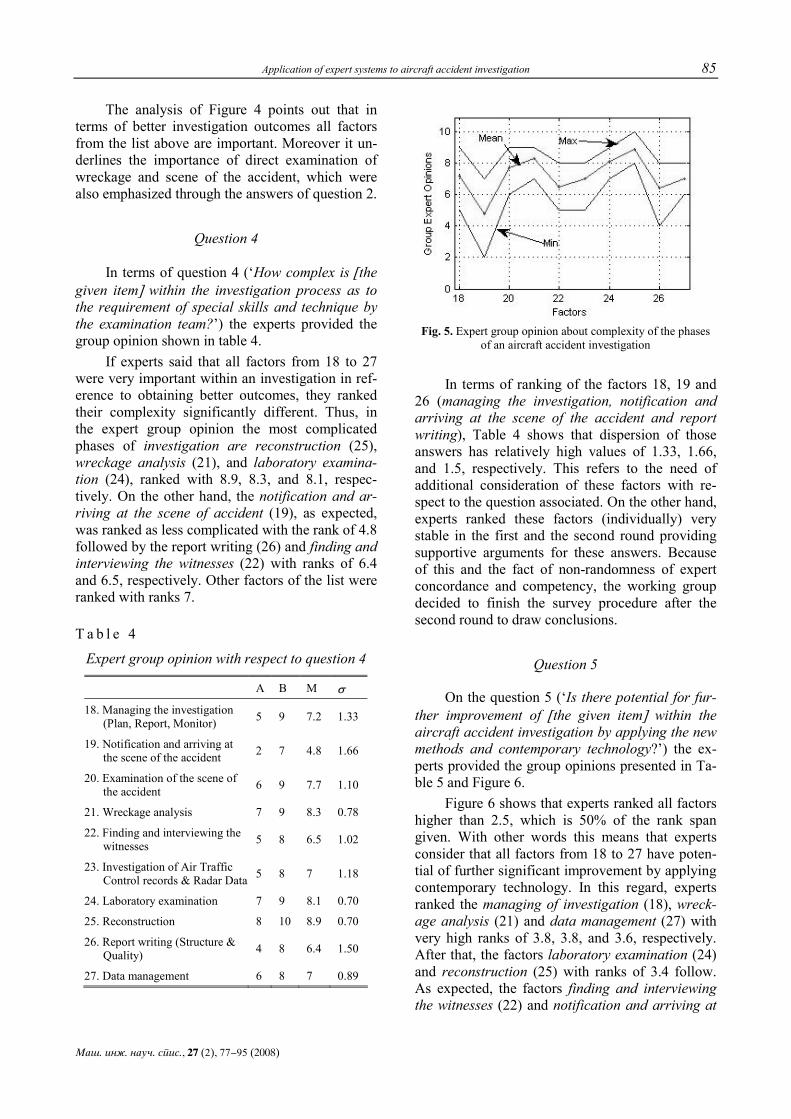
Application of expert systems to aircraft accident investigation 85
Ma{. in`. nau~. spis., 27 (2), 77‡95 (2008)
The analysis of Figure 4 points out that in terms of better investigation outcomes all factors from the list above are important. Moreover it un-derlines the importance of direct examination of wreckage and scene of the accident, which were also emphasized through the answers of question 2.
Question 4
In terms of question 4 (‘How complex is [the given item] within the investigation process as to the requirement of special skills and technique by the examination team?’) the experts provided the group opinion shown in table 4.
If experts said that all factors from 18 to 27 were very important within an investigation in ref-erence to obtaining better outcomes, they ranked their complexity significantly different. Thus, in the expert group opinion the most complicated phases of investigation are reconstruction (25), wreckage analysis (21), and laboratory examina-tion (24), ranked with 8.9, 8.3, and 8.1, respec-tively. On the other hand, the notification and ar-riving at the scene of accident (19), as expected, was ranked as less complicated with the rank of 4.8 followed by the report writing (26) and finding and interviewing the witnesses (22) with ranks of 6.4 and 6.5, respectively. Other factors of the list were ranked with ranks 7.
T a b l e 4
Expert group opinion with respect to question 4
A B M σ
18. Managing the investigation (Plan, Report, Monitor) 5 9 7.2 1.33
19. Notification and arriving at the scene of the accident 2 7 4.8 1.66
20. Examination of the scene of the accident 6 9 7.7 1.10
21. Wreckage analysis 7 9 8.3 0.78
22. Finding and interviewing the witnesses 5 8 6.5 1.02
23. Investigation of Air Traffic Control records & Radar Data 5 8 7 1.18
24. Laboratory examination 7 9 8.1 0.70
25. Reconstruction 8 10 8.9 0.70
26. Report writing (Structure & Quality) 4 8 6.4 1.50
27. Data management 6 8 7 0.89
Fig. 5. Expert group opinion about complexity of the phases
of an aircraft accident investigation
In terms of ranking of the factors 18, 19 and 26 (managing the investigation, notification and arriving at the scene of the accident and report writing), Table 4 shows that dispersion of those answers has relatively high values of 1.33, 1.66, and 1.5, respectively. This refers to the need of additional consideration of these factors with re-spect to the question associated. On the other hand, experts ranked these factors (individually) very stable in the first and the second round providing supportive arguments for these answers. Because of this and the fact of non-randomness of expert concordance and competency, the working group decided to finish the survey procedure after the second round to draw conclusions.
Question 5
On the question 5 (‘Is there potential for fur-ther improvement of [the given item] within the aircraft accident investigation by applying the new methods and contemporary technology?’) the ex-perts provided the group opinions presented in Ta-ble 5 and Figure 6.
Figure 6 shows that experts ranked all factors higher than 2.5, which is 50% of the rank span given. With other words this means that experts consider that all factors from 18 to 27 have poten-tial of further significant improvement by applying contemporary technology. In this regard, experts ranked the managing of investigation (18), wreck-age analysis (21) and data management (27) with very high ranks of 3.8, 3.8, and 3.6, respectively. After that, the factors laboratory examination (24) and reconstruction (25) with ranks of 3.4 follow. As expected, the factors finding and interviewing the witnesses (22) and notification and arriving at

86 G. Milošovski, C. Bil, M. Ćosevski
Mech. Eng. Sci. J., 27 (2), 77–95 (2008)
the scene of accident (19) were ranked with the lowest ranks, but still high of 2.55 and 2.9, respec-tively.
T a b l e 5
Expert group opinion with respect to question 5
A B M σ
18. Managing the investigation (Plan, Report, Monitor) 3 4.5 3.8 0.56
19. Notification and arriving at the scene of the accident 2 4 2.9 0.70
20. Examination of the scene of the accident 2.5 4 3.3 0.51
21. Wreckage analysis 3 4.5 3.8 0.56
22. Finding and interviewing the witnesses 1.5 3 2.55 0.61
23. Investigation of Air Traffic Control records & Radar Data 2.5 4 3.2 0.56
24. Laboratory examination 3 4 3.4 0.49
25. Reconstruction 2.5 4 3.4 0.54
26. Report writing (Structure & Quality) 2 4 3 0.77
27. Data management 3 4 3.6 0.44
Fig. 6. Expert group opinion relating to the potential for improving the phases of an aircraft accident investigation
Answers of questions 3, 4 and 5 provide use-ful information about the investigation phases pre-sented individually in figures 4–6. As those an-swers are related to the same factors 18–27, they can also be plotted in a 3-D space with respect to importance (x-axis), complexity (y-axis) and im-provement (z-axis).
Hence, using the data from the tables 3–5, the Figure 7 was created and additionally Figure 8, which provide better outlook of data derived.
Fig. 7. Location of ranks of the phases of an aircraft accident
investigation in 3-D space created of their importance, complexity and potential of their further improvement
Overall the Figure 7 indicates that all factors 18–27 are located in the space with high ranks of the x, y, and z axis. In order to provide a better view of those ranks, those results were additionally resolved into three planes (‘xy’, ‘xz’, and ‘yz’ ele-vation) shown in Figure 8.
Figure 8 clearly illustrates the position of ex-pert group opinions of questions 3, 4, and 5, related to the factors 18–27. It can be seen that the factor wreckage analysis (21), with the coordinates/ranks of (9.5, 8.3, and 3.8) has most dominant position among all factors followed by laboratory examina-tion (24) and reconstruction (25), also with high ranks of (8.7, 8.1, 3.4) and (7.9, 8.9, 3.4), respec-tively.
Moreover, the Figure 8 shows that the factors managing the investigation (18), data management (27), examination of the scene of the accident (20) also have high ranks, but are a little lower than the above mentioned factors 21, 24, 25. From the Fig-ure 8 it can be seen that the factors notification and arriving at the scene of the accident (19), finding and interviewing the witnesses (22), and report writing (26) were ranked the lowest among all fac-tors with (8.6, 4.8, 2.9), (8.2, 6.5, 2.5), (8.2, 6.4, 3), respectively.
The results of questions 3, 4, 5, as a whole, point out that in order to obtain significant en-hancement of the process of aircraft accident in-vestigation, interested parties must focus their ef-forts towards development of the three general fac-tors wreckage analysis (21), laboratory examina-tion (24) and reconstruction (25).

Application of expert systems to aircraft accident investigation 87
Ma{. in`. nau~. spis., 27 (2), 77‡95 (2008)
Fig. 8. Expert group opinion with respect to questions 3, 4, 5
Question 6
With respect to the question 6 (‘How complex is the examination of [the given item] as to the re-quirement of special skills and technique by the examination team?’) the experts provided the group opinions presented in Table 6 and Figure 9.
According to Figure 9, the examination of all factors 28–53 is complex and requires special skills by the examination team. Experts allocated maximum ranks to the factors in-flight explosion (41), in-flight failure (42), psychological human factors (52), human error and omission (51), and design inadequacy (53), with ranks of 9.2, 9, 8.9, 8.8, and 8.6, respectively.
On the other hand the factors landing gear systems and brake systems (32), fuel (34), and air-craft loading (39) were considered as less complex among all factors from the list, with ranks of 6.3, 6.3, and 6.4, respectively. The ranks of other fac-tors were between 6.3 and 9.2.
From the Table 6 high values of dispersion σ for the factors landing gear and brake systems (32), de-icing and anti-icing systems (33), fuel (34), aircraft loading (39), in-flight fire (43), light-ning (44), and mid-air collision (45) can be seen. This indicates that there is a considerable differ-ence in expert opinions for those factors, which deserve a special attention. Considering this situa-
tion, the working group deduced that experts did not alter their original answers significantly from the first into the second round providing a suppor-tive argument for these ranks.
Yet, the positive tests of non-randomness of expert concordance and competency for all ques-tions were a sufficient argument working group in these circumstances to accept those ranks as final. It should be clarified that current extreme answers did not significantly affect the mean of answers presented in the Table 6.
Fig. 9. Expert group opinion about the complexity of wreckage examination and other factors within
an investigation

88 G. Milošovski, C. Bil, M. Ćosevski
Mech. Eng. Sci. J., 27 (2), 77–95 (2008)
T a b l e 6
Expert group opinion with respect to question 6
A B M σ
28. Operations, The Flight Path 7 9 7.9 0.83
29. Cockpit 7 10 8.4 1.20
30. Engine and accessories 7 10 8.3 1.10
31. Mechanical, electrical, hydraulic, pneumatic systems 7 10 8.4 1.11
32. Landing gear systems and brake systems 4 8 6.3 1.49
33. De-icing and anti-icing systems 4 9 6.7 1.85
34. Fuel (quality and amount) 3 9 6.3 2.19
35. Foreign Object Damage (FOD) 5 9 7 1.61
36. Cockpit Voice Recorder (CVR) 7 9 7.9 0.83
37. Cockpit Sound Recorder (CSR) 7 9 8.1 0.70
38. Flight Data Recorder (FDR) 7 9 8.1 0.70
39. Aircraft loading 3 9 6.4 2.20
40. Hydroplaning 6 9 7.5 1.20
41. In-flight explosion 8 10 9.2 0.75
42. In-flight failure (Structural failure–fatigue) 8 10 9 0.89
43. In-flight fire 6 10 8.2 1.54
44. Lightning 5 9 7.6 1.50
45. Mid-air collision 3 9 7.2 2.18
46. Crime activities 6 9 7.7 1.10
47. Weather conditions 7 9 7.8 0.75
48. Downwash and wing tip vortex hazards 7 9 8 0.77
49. Microburst, wind gust, wind shear 7 9 8 0.77
50. Stability and control of an airplane 7 10 8.1 1.22
51. Human error or omission 8 9 8.8 0.40
52. Psychological factors (fatigue, illusion, etc.) 8 10 8.9 0.70
53. Design inadequacy 8 10 8.6 0.66
Question 7
Table 7 shows the expert opinions about question 7 (‘Is there potential for further improve-ment of examination of [the given item] within the aircraft accident investigation by applying new methods and contemporary technology?’) within the Delphi enquiry. Accordingly Figure 10 was created.
Figure 10 presents the expert opinions about the potential of further improvement of the exami-
nation of the factors 28–53. Overall experts ranked all factors (except the factor fuel examination) greater than 2.5, which is 50% of the rank span given. Differently than the results from Table 6, here, experts ranked all factors very stable creating small values of dispersion σ.
T a b l e 7
Expert group opinion with respect to question 7
A B M σ
28. Operations, The Flight Path 3 4 3.4 0.49
29. Cockpit 2 4 3.25 0.68
30. Engine and accessories 2 4 3.3 0.78
31. Mechanical, electrical, hydraulic, pneumatic systems 2.5 4 3.65 0.55
32. Landing gear systems and brake systems 2 4 2.9 0.83
33. Deicing and anti-icing systems 2 4 2.9 0.83
34. Fuel (quality and amount) 1 3.5 2.2 0.95
35. Foreign Object Damage 2 4 3 0.63
36. Cockpit Voice Recorder 3 5 3.9 0.70
37. Cockpit Sound Recorder 2.5 5 3.75 0.81
38. Flight Data Recorder 3 5 3.8 0.75
39. Aircraft loading 2.5 4.5 3.3 0.71
40. Hydroplaning 2 4 3.1 0.83
41. In-flight explosion 2.5 5 3.8 0.95
42. In-flight failure (Structural failure–fatigue) 2.5 5 3.7 0.87
43. In-flight fire 3 5 3.5 0.67
44. Lightning 2 4 3 0.59
45. Mid-air collision 2 4 3.2 0.75
46. Crime activities 2.5 5 3.6 0.89
47. Weather conditions 2.5 4.5 3.6 0.62
48. Downwash and wing tip vortex hazards 3 5 3.6 0.80
49. Microburst, wind gust, wind shear 3 4 3.4 0.49
50. Stability and control of an airplane 2 4.5 3.25 0.78
51. Human error or omission 2.5 5 3.95 0.85
52. Psychological factors (fatigue, illusion, etc) 3 5 4 0.77
53. Design inadequacy 3 4.5 3.45 0.57

Application of expert systems to aircraft accident investigation 89
Ma{. in`. nau~. spis., 27 (2), 77‡95 (2008)
Fig. 10. Expert group opinion about the potential of improvement of wreckage examination and other factors
within an investigation
The maximum ranks of 4, 3.9, 3.9, 3.8, 3.8, 3.8, and 3.7 were allocated to the examination of the following factors: psychological factors (52), human error or omission (51), cockpit voice re-corder (36), flight data recorder (38), in–flight explosion (41), cockpit sound recorder (37), in-flight failure (42), respectively.
In contrast, experts ranked the factors fuel (34), landing gear and brake systems (32), de-icing and anti-icing systems (33), foreign object damage (35), and lightning (44) with significantly lower ranks of 2.2, 2.9, 2.9, 3, and 3, respectively.
In addition Figure 11 is discussed which combines the answers from the question 6 and the question 7 referring to factors 28–53. Figure 11 illustrates the mutual correlation of complexity (‘complexity’) and the potential of improvement of examination (‘improvement’) of factors 28–53, disposing them into ‘xy’ area, where ‘x’ axis is ‘complexity’ and ‘y’ axis is ‘improvement’.
According to the location of factors in Figure 11, two different groups of factors with different features can be created. The first group is located in the right upper corner of the chart and those fac-tors have both high ranks of ‘complexity’ and ‘im-provement’, whereas the second group is com-posed of factors with significantly smaller values of ‘complexity’ and slightly lower ranks of ‘im-provement’. Hence, most of factors 28–53 are lo-cated in the first group and among them the most distinguished are the following ones: in-flight ex-plosion (41), in-flight failure 42, psychological factors (52), and human error or omission (51) with coordinates/ranks of (9.2, 3.8), (9, 3.7), (8.9, 4), (8.8, 3.9), respectively.
Fig. 11. Complexity and potential of improvement of examination of the given factors within an aircraft accident
investigation
The second group is composed of the factors: fuel (34), landing gear systems and brake systems (32), de-icing and anti-icing systems (33), foreign object damage (35), mid-air collision (45), aircraft loading (39), ranked as follows: (6.3, 2.2), (6.3, 2.9), (6.7, 2.9), (7, 3), (7.2, 3.2), (6.4, 3.3), respec-tively.
The presented distribution from Figure 11 may indicate the direction of improvement of the process of the aircraft accident investigation. This analysis refers to factors with the highest ranks such as in-flight explosion (41), in-flight failure 42, psychological factors (52), and human error or omission (51).
Question 8
According to the expert opinions of question 8 (‘What are the odds of proving within the proc-ess of an aircraft accident investigation that [the given item] is one of the major causes for an acci-dent?’), Table 8 and Figure 12 were created.
Figure 12 illustrates very tangible data reveal-ing the items which are likely to be determined during the investigation as major causes of acci-dent, or otherwise, items that are very difficult to determine although they have a significant contri-bution to an accident occurrence.
Thus, experts ranked the factors mid-air colli-sion (74), landing gear systems malfunction (56), brake system malfunction (55), with very high ranks of 9.2, 8.9, and 8.5, respectively, which show that those events are most likely to be recognized during an investigation and examined properly.
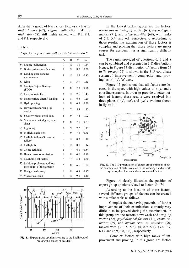
90 G. Milošovski, C. Bil, M. Ćosevski
Mech. Eng. Sci. J., 27 (2), 77–95 (2008)
After that a group of few factors follows such as in flight failure (67), engine malfunction (54), in flight fire (68), still highly ranked with 8.3, 8.1, and 8.1, respectively.
T a b l e 8
Expert group opinion with respect to question 8
A B M σ
54. Engine malfunction 7 10 8.1 1.14 55. Brake systems malfunction 8 9 8.5 0.50 56. Landing gear systems
malfunction 8 10 8.9 0.83
57. Icing 4 8 5.9 1.45 58. Foreign Object Damage
(FOD) 6 8 7.3 0.78
59. Inappropriate fuel 6 10 7.6 1.43 60. Inappropriate aircraft loading 5 8 6.6 1.20 61. Hydroplaning 6 8 6.9 0.70 62. Downwash and wing tip
vortex 3 7 5.3 1.42
63. Severe weather conditions 6 9 7.4 1.02 64. Microburst, wind gust, wind
shear 6 8 7.1 0.83
65. Lightning 6 9 7.2 1.17 66. In-flight explosion 7 9 7.8 0.75 67. In-flight failure (Structural
failure) 7 10 8.3 1.10
68. In-flight fire 7 10 8.1 1.14 69. Crime activities 5 7 6.1 0.54 70. Human error or omission 6 8 6.6 0.80 71. Psychological factors 4 7 5.4 0.80 72. Stability problems and lost
the control of the airplane 5 8 6.6 1.02
73. Design inadequacy 6 8 6.8 0.87 74. Mid air collision 9 10 9.2 0.40
Fig. 12. Expert group opinions relating to the likelihood of
proving the causes of accident
In the lowest ranked group are the factors: downwash and wing tip vortex (62), psychological factors (71), and crime activities (69), with ranks of 5.3, 5.4, and 6.1, respectively. According to those results, the examination of those factors is complex and proving that those factors are major causes for accident it is a significantly difficult task.
The ranks provided of questions 6, 7 and 8 can be combined and presented in 3-D distribution. Hence, in Figure 13 distribution of factors from 54 to 74 (except 55) is shown in the 3-D coordinate system of ‘improvement’, ‘complexity’, and ‘prov-ing’ as ‘x’, ’y’, ’z’ axes.
Figure 13 points out that all factors are lo-cated in the space with high values of x, y, and z coordinates/ranks. In order to provide a better out-look of factors, these results were resolved into three planes (‘xy’, ‘xz’, and ‘yz’ elevation) shown in figure 14.
Fig. 13. The 3-D presentation of expert group opinions about the examination of factors related to the wreckage and aircraft
systems, then human and environmental factors
Figure 14 clearly illustrates the position of expert group opinions related to factors 54–74.
According to the location of these factors, several different groups of factors can be created with similar ranks as follows:
– Complex factors having potential of further improvement of their examination, currently very difficult to be proved during the examination. In this group are the factors downwash and wing tip vortex (62), psychological factors (71), crime ac-tivities (69) and human error or omission (70) ranked with (3.6, 8, 5.3), (4, 8.9, 5.4), (3.6, 7.7, 6.1), and (3.9, 8.8, 6.6) , respectively.
– Complex factors with high ranks of im-provement and proving. In this group are factors

Application of expert systems to aircraft accident investigation 91
Ma{. in`. nau~. spis., 27 (2), 77‡95 (2008)
such as in-flight failure (67), in-flight explosion (66), in-flight fire (68), engine malfunction (54), with ranks (3.7, 9, 8.3), (3.8, 9.2, 7.8), (3.5, 8.2, 8.1) and (3.3, 8.3, 8.1), respectively.
– Factors with moderately high ranks of im-provement, complexity and proving. In this group
there are a number of factors such as foreign object damage (58), inappropriate aircraft loading (60), hydroplaning (61) and so on with ranks of (3, 7, 7.3), (3.3, 6.4, 6.6), (3.1, 7.5, 6.9), respectively.
Fig. 14. Expert group opinion with respect to questions 6, 7, 8
The above analysis shows that experts with their answers again indicate a general potential of significant improvement of the process of aircraft accident investigation. Accordingly, the prospec-tive improvement of investigation can be expected particularly in the examination of human factors followed by the examination of aircraft systems.
Question 9
With respect to the last question (‘Do you agree with the statements below?’) experts pro-vided the following group opinions presented in Table 9 and Figure 15.
The first impression is that experts did not al-locate extremely high ranks to any of those state-ments so that most factors were moderately ranked between 6 and 7.
Another remark is that dispersion of expert opinions about several questions reached very high value. Experts firmly kept their opinions after the
second round of the survey so that the high values of dispersion could not have been reduced through the feedback. The results remain scientifically ac-cepted, because the statistical tests of expert com-petency and concordance justified the non-randomness of expert opinions. According to the results, several groups of factors were created, as follows:
a) Highest ranks were allocated to the factors 79 and 90 with 8.1 and 8, respectively. Namely, experts said that excellent knowledge of theory can significantly improve the investigation outcomes (79) as well as determining that the weather condi-tion during an accident is not a very tough task (90).
b) Experts granted several factors with ranks between 7 and 8. These factors are (76), (91), (75), (89), (97) which state that:
Waiting for a couple of months for releasing the accident investigation report is justifiable (rank 7.6).

92 G. Milošovski, C. Bil, M. Ćosevski
Mech. Eng. Sci. J., 27 (2), 77–95 (2008)
Human factors are involved somehow in every single aircraft accident (rank 7.2).
The process of investigation meets the high standards of quality assurance and quality con-trol procedures (7.2).
The downwash and wing tip vortex are serious hazards for the aircraft (7.2).
The process of investigation as a whole can be improved significantly by applying new meth-ods and advanced technology (7)
T a b l e 9
Expert group opinion with respect to question 9
A B M σ A B M σ
75. The process of investigation meets the procedures regarding the quality assurance (QA) and quality control (QC)
5 8 7.2 0.98
87. The aircraft is equipped with appropriate accessories, which provides ice protection during the whole flight
4 8 6 1.34
76. It is justifiable waiting for a couple of months for releasing the accident investigation report
6 9 7.6 0.92 88. The stall is a serious hazard for the aircrafts 4 8 6 1.34
77. Reports of investigation carried out are always accurate and well done 5 8 6.5 1.20 89. The downwash and wing tip vortex is
a serious hazard for the aircrafts 6 9 7.2 0.87
78. Investigators have appropriate and sufficient skills to handle aircraft accident investigation
5 8 6.7 1.10 90. Investigators have enough resources
available to find out the weather conditions during the accident
5 9 8 1.18
79. The excellent knowledge of theory compared the average one improves significantly the investigation outcomes
7 9 8.1 0.83 91. Human factors have been involved
somehow in every single aircraft accident that has ever occurred
4 8 7.2 1.25
80. The contamination of the scene of the accident is a serious problem within the process of aircraft accident investigations
5 9 7 1.41 92. It is possible to answer the question
if the pilot should have been able to cope with the critical situation
5 8 6.3 1.10
81. The presence of landmarks on the scene of the accident provides sufficient information for carrying out accurate mathematical calculations
5 7 5.9 0.70 93. There are always problems with
airfield papers analysis (documentation)
4 7 5.4 1.11
82. It is likely at times inconsistent material has been sent for lab analysis
5 7 5.7 0.78 94. The handbook is good composed material 5 8 6.2 1.08
83. Investigators should believe witnesses of aircraft accident 3 6 4.8 1.25
95. There is a great possibility for increasing the survivability of an aircraft accident
4 8 6.4 1.50
84. The cockpit recorders (FDR, CVR, CDR) record sufficient parameters 2 8 5.5 2.11
96. Determining the cause of the accidents is a very tough task if there is not data recorded
3 8 6.2 1.89
85. We never have a real accident with enough readable data 2 5 4.1 1.22
97. The process of investigation as a whole can be improved significantly, by applying new methods and advanced technology
5 9 7 1.34
86. The severe aircraft maneuvers can be revealed during the investigation 4 9 6.9 1.70
98. The experience of the land traffic accident investigation can contribute to considerable increase of air traffic safety
5 8 6.2 1.25
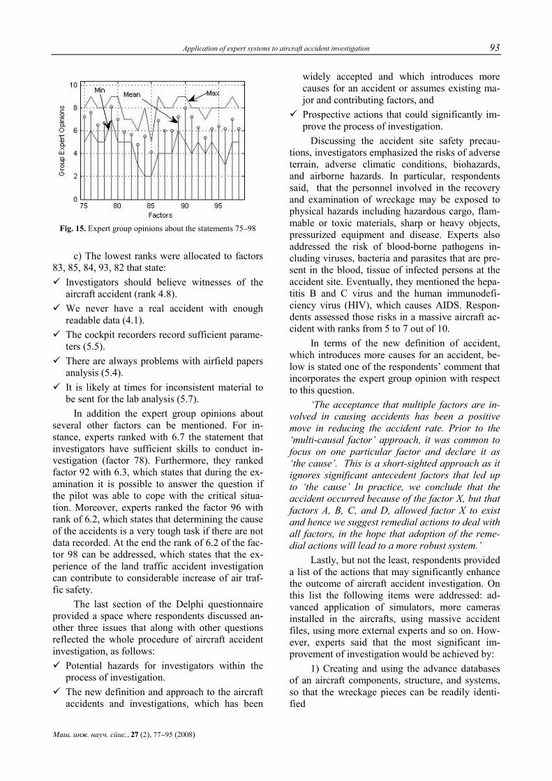
Application of expert systems to aircraft accident investigation 93
Ma{. in`. nau~. spis., 27 (2), 77‡95 (2008)
Fig. 15. Expert group opinions about the statements 75–98
c) The lowest ranks were allocated to factors 83, 85, 84, 93, 82 that state:
Investigators should believe witnesses of the aircraft accident (rank 4.8).
We never have a real accident with enough readable data (4.1).
The cockpit recorders record sufficient parame-ters (5.5).
There are always problems with airfield papers analysis (5.4).
It is likely at times for inconsistent material to be sent for the lab analysis (5.7).
In addition the expert group opinions about several other factors can be mentioned. For in-stance, experts ranked with 6.7 the statement that investigators have sufficient skills to conduct in-vestigation (factor 78). Furthermore, they ranked factor 92 with 6.3, which states that during the ex-amination it is possible to answer the question if the pilot was able to cope with the critical situa-tion. Moreover, experts ranked the factor 96 with rank of 6.2, which states that determining the cause of the accidents is a very tough task if there are not data recorded. At the end the rank of 6.2 of the fac-tor 98 can be addressed, which states that the ex-perience of the land traffic accident investigation can contribute to considerable increase of air traf-fic safety.
The last section of the Delphi questionnaire provided a space where respondents discussed an-other three issues that along with other questions reflected the whole procedure of aircraft accident investigation, as follows:
Potential hazards for investigators within the process of investigation.
The new definition and approach to the aircraft accidents and investigations, which has been
widely accepted and which introduces more causes for an accident or assumes existing ma-jor and contributing factors, and
Prospective actions that could significantly im-prove the process of investigation.
Discussing the accident site safety precau-tions, investigators emphasized the risks of adverse terrain, adverse climatic conditions, biohazards, and airborne hazards. In particular, respondents said, that the personnel involved in the recovery and examination of wreckage may be exposed to physical hazards including hazardous cargo, flam-mable or toxic materials, sharp or heavy objects, pressurized equipment and disease. Experts also addressed the risk of blood-borne pathogens in-cluding viruses, bacteria and parasites that are pre-sent in the blood, tissue of infected persons at the accident site. Eventually, they mentioned the hepa-titis B and C virus and the human immunodefi-ciency virus (HIV), which causes AIDS. Respon-dents assessed those risks in a massive aircraft ac-cident with ranks from 5 to 7 out of 10.
In terms of the new definition of accident, which introduces more causes for an accident, be-low is stated one of the respondents’ comment that incorporates the expert group opinion with respect to this question.
‘The acceptance that multiple factors are in-volved in causing accidents has been a positive move in reducing the accident rate. Prior to the ‘multi-causal factor’ approach, it was common to focus on one particular factor and declare it as ‘the cause’. This is a short-sighted approach as it ignores significant antecedent factors that led up to ‘the cause’ In practice, we conclude that the accident occurred because of the factor X, but that factors A, B, C, and D, allowed factor X to exist and hence we suggest remedial actions to deal with all factors, in the hope that adoption of the reme-dial actions will lead to a more robust system.’
Lastly, but not the least, respondents provided a list of the actions that may significantly enhance the outcome of aircraft accident investigation. On this list the following items were addressed: ad-vanced application of simulators, more cameras installed in the aircrafts, using massive accident files, using more external experts and so on. How-ever, experts said that the most significant im-provement of investigation would be achieved by:
1) Creating and using the advance databases of an aircraft components, structure, and systems, so that the wreckage pieces can be readily identi-fied

94 G. Milošovski, C. Bil, M. Ćosevski
Mech. Eng. Sci. J., 27 (2), 77–95 (2008)
2) Creating and using massive databases for storing and analyzing the data of aircraft accidents.
3) Video camera recording various functions and aircraft zones and data transmitted to the ground stations and continually recorded.
Overall by applying those actions (measures), experts ranked the prospective improvement of an aircraft accident investigation between 5 and 7 out of 10.
8. CONCLUSION
The Delphi exercise managed to look into the process of aircraft accident investigation. Experts discussed 98 questions from different aspects and ranked their impact on investigation outcomes. Expert opinions through the feedback were re-evaluated and up-grated leading to the following conclusions:
Overall, there is a great potential of further improvement of an aircraft accident investigation, particularly the portions of managing the investiga-tion, wreckage analysis, and data management (Table 5).
First of all, the procedure of dispatching in-vestigators on the scene of the accident and the process of coordination and cooperation between investigators within an investigation could be im-proved (Table 1). Next, there is a great potential of further improvement of investigation of human error and omission and psychological human fac-tors, as well as investigation of data recorders, and in-flight occurrences such as aircraft system fail-ure, explosion and so on (Table 7). In addition, the Delphi enquiry addresses the need of seeking new approaches and methods for analyzing the crime activities as a possible cause for accidents (Table 7, factor 46). Finally, managing the amount of time and money spent within investigations could be improved (Table 1).
In terms of prospective solutions for im-provement of aircraft accident outcomes, first of all, experts said that excellent investigators’ knowledge of theory can significantly enhance the investigation results (Table 9, factor 79). In addi-tion they address that determining the cause of the accident is a very difficult task without data re-corded. Therefore experts propose creating and using the advance database for easily identification of aircraft’s components as well as creating and using massive databases for storing and analyzing the data of aircraft accidents. Moreover, they sug-
gest implementing of common video recording of various functions and aircraft zones and transmit-ting the data to the ground stations for storing.
Finally, taking all results above into account the Delphi outcomes address the need for a tool, which will be able to:
– Include and contain specific knowledge and the analytical skills of a large number of experts.
– Communicate the impact of a huge number of causal factors on air traffic safety.
As a result of this, the conclusion emerges that aircraft accidents investigation could be im-proved with the application of a global expert sys-tem as a tool for storing and analysing the forensic data of aircraft accidents worldwide with the op-tion to learn from aircraft accidents using an infer-ence engine to propose possible causes based on forensic data provided. Such a system will ensure that valuable data is not lost and is used to its full potential.
REFERENCES
[1] Chorafas D.: Modelling the survival of financial and in-dustrial enterprises, Palgrave Macmillan, New York (2002).
[2] Dobrov G. M.: Prognostik in Wiessenschaft und Technik, Pietz Verlag, Berlin (1971).
[3] Ferguson S. D.: Researching the public opinion environ-ment, Sage Publications, Thousand Oaks (2000).
[4] Harold A. L., Murray T.: The Delphi Method, Addison – Wesley Publishing Company, Don Mills (1975).
[5] Aircraft Accident and Incident Investigation, ICAO (2001).
[6] Manual of Aircraft Accident Investigation, ICAO (1970). [7] Kennedy H. P.: Enhancing Delphi research: methods and
results, Journal of Advanced Nursing 45 (5), 504–511 (2004).
[8] Krause S.: Aircraft Safety, MCGraw-Hill (1996). [9] Kuzinovski M., Tudžarova S., Chihosh P., Zembrovski
H.: ‘Application of the Delphi technique – A guarantee to perform successful investigations’, Collection of articles, Faculty of Mechanical Engineering, Skopje (1994),
[10] Kuzinovski M., Chihosh P., Tudžarova S.: ‘Computer aided realization of the Delphi Method’, Collection of ar-ticles, University ‘St. Cyril and Metodious’, Skopje, (1998).
[11] Litvak B. G.: Ekspertnaja informacija. Metody polucheni-ja i analiza. Radio i svjaz', Moskva (1982).
[12] Matejic V.: Forecasting by applying the Delphi tech-nique, Institute ‘Mihailo Pupin’, Beograd (1974).
[13] Miyagi M.: Serious Accident and Human Factors, John Wiley & Sons Ltd, West Sussex, (2005)
[14] Novačevski D.: Methods of creating set priorities, Con-temporary administration, Beograd (1980).

Application of expert systems to aircraft accident investigation 95
Ma{. in`. nau~. spis., 27 (2), 77‡95 (2008)
[15] Novačevski D.: Annuaire de la faculte des sciences economiques de Skopje, L’Universite ‘Cyrile et Meth-ode’, Skopje (1978).
[16] Quade E. S.: Analysis for Public Policy Decisions, the RAND Corporation, Santa Monica (1972).
[17] Wood Richard H., Sweginnis Robert W.: Aircraft Acci-dent Investigation, Endeavor Books, Casper, WY (2006).
[18] Spata A.: Research methods, John Wiley & Sons, Inc., New York (2003).
[19] Sandelowski M.: Combining qualitative and quantitative sampling, data collection, and analysis techniques in mixed-method studies, Research in Nursing & Health (2000).
[20] Vrcelj D., Bajić V., Zivotić P., Petrović P.: Measuring of the technological progress and methods for forecasting, Institute of Economic Industry, Beograd (1973).
[21] Wells A.: Commercial Aviation Safety, McGraw-Hill (2001).
R e z i m e
PRIMENA NA EKSPERTSKI SISTEMI VO ISTRAGA NA AVIONSKI NEZGODI
Goran Milo{ovski1, Cees Bil1, Milan ]osevski2
1School of Aerospace, Mechanical and Manufacturing Engineering, RMIT University, Melbourne, Australia
2Ma{inski fakultet, Univerzitet „Sv. Kiril i Metodij“, p. fah. 464, MK-1001 Skopje, Republika Makedonija
[email protected] // [email protected]
Klu~ni zborovi: ekspertski sistemi; metod Delfi; istraga na avionska nezgoдa
Vo minatiot ima postoi zna~itelen razvoj na nau~nite metodi za analiza na kompleksni procesi i kreirawe na lista prioriteti za nivno ponatamo{no unapreduvawe. Glavna cel od primenata na tie me-todologii e definirawe na optimalno re{enie, koe se bazira na raspolo`livite informacii, strate{-kite celi i procenata za idnata sostojba na procesot koj se analizira. Interdisciplinarniot pristap i intuicijata se poka`aa kako glavni elementi vo razvivaweto na sovremenite metodi za analizirawe na kompleksni procesi. Kako rezultat, vo minatite nekolku decenii se razvieni pogolem broj intuitiv-ni metodi, od koi metodot Delfi e naj~esto i naj-efektivno primenuvan. Ovoj trud prika`uva rezulta-ti od koristeweto na metodot Delfi zaradi podobru-vawe na istraga na avionsnki nezgodi. Imeno, trudot
gi identifikuva delovite od procesot na istragata kade {to zna~itelno podobruvawe mo`e da se postig-ne so primena na sovremena tehnologija i metodi. Po-toa se prika`ani rezultatite od izvr{enata kvanti-tativna i kvalitativna analiza na faktorite koi imaat vlijanie na krajnite rezultati od istragata. Vo zaklu~kot ovoj trud uka`uva deka istragata na avionska nezgoda mo`e da se podobri so upotreba na kompjuterska alatka, koja }e sodr`i specifi~no znaewe i ve{tina od golem broj eksperti, odnosno deka istragata na avionska nezgoda zna~itelno mo`e da se podobri so primena na globalen ekspertski sis-tem kako {to e kompjuterska programa za skladirawe i analizirawe na podatoci od prethodno izvr{eni avionski nezgodi.
Mechanical Engineering – Scientific Journal, Vol. 27, No. 2, pp. 97–105 (2008) CODEN: MINSC5 – 397 ISSN 1857–5293 Received: September 29, 2008 UDK: 656.7.082:004.94 Accepted: October 8, 2008
Original scientific paper
DEMONSTRATION OF EXPERT SYSTEMS TO AIRCRAFT ACCIDENT INVESTIGATION
Goran Milošovski, Cees Bil, Paul Simon, Milan Ćosevski
School of Aerospace, Mechanical and Manufacturing Engineering, RMIT University, Melbourne, Australia
[email protected] // [email protected] // [email protected]
Abstract. Research is being conducted at the RMIT University on the ‘Improvement of Aircraft Accident Investiga-tion through Expert Systems’. The outcome of this research presented in this paper is a novel investigation tool in the form of a data mining method designed towards giving aircraft acci-dent investigators improved utilization of forensic data. The tool, named GP1020, is primarily a data sorting tool that sifts through a huge amount of data, namely those regarding aircraft accidents/incidents and investigations conducted including a number of causal factors for accidents/incidents associated with their consistent evidence. The GP1020 program interface asks the user a tree-based set of questions related to the conditions of wreckage, accident site and other circumstances relevant to accidents/incidents. Given enough information, the program is capable of narrowing down all known possibilities to indicate the most probable cause(s) of the accident/incident.
Key words: expert systems; aircraft accident investigation
1. INTRODUCTION
The research project ‘Improvement of Aircraft Accident Investigation through Expert Systems’ aims to analyse the current accident investigation process and to review some of the off-the-shelf tools that support these investigations. An analysis of the process and tools will provide a possible ave-nue for updating the investigation process and im-plementing mitigation measures to enhance air traf-fic safety. The research framework is presented be-low in Figure 1.
The work starts with discussing the procedure of the aircraft accident investigation, which is de-fined as a process conducted for the purpose of ac-cident prevention and focused on the circumstances of the accident including gathering, recording and analysis of all available information, the drawing of
conclusions, including the determination of acci-dent causes [3].
The work starts with discussing the procedure of the aircraft accident investigation, which is de-fined as a process conducted for the purpose of ac-cident prevention and focused on the circumstances of the accident including gathering, recording and analysis of all available information, the drawing of conclusions, including the determination of acci-dent causes [3].
Despite the attitude and commitments to achieve the above purpose, accident investigations may become a cumbersome work associated with significant costs and uncertainty. This can poten-tially contribute to some accidents being assigned an unknown cause as described in the global air-craft accident statistics for the past 50 years. There-fore, the investigation process has been subjected to a constant review in order to improve its outcomes and to help enhance air traffic safety.
The work concludes that an intuitive and in-terdisciplinary approach must be vital elements of any contemporary methods used for establishing a set of priorities for further improvement of the air-craft accident investigation process. Hence interpo-lations methods including an analysis of accident statistics and the Delphi enquire are appropriate tools in analysing and drawing conclusions for fur-ther improving the investigation process. The statis-tical data examined contained the number of acci-dents which occurred between 1950 and 2004 in-cluding the accident distribution over the past, causal factors, and casualty count.
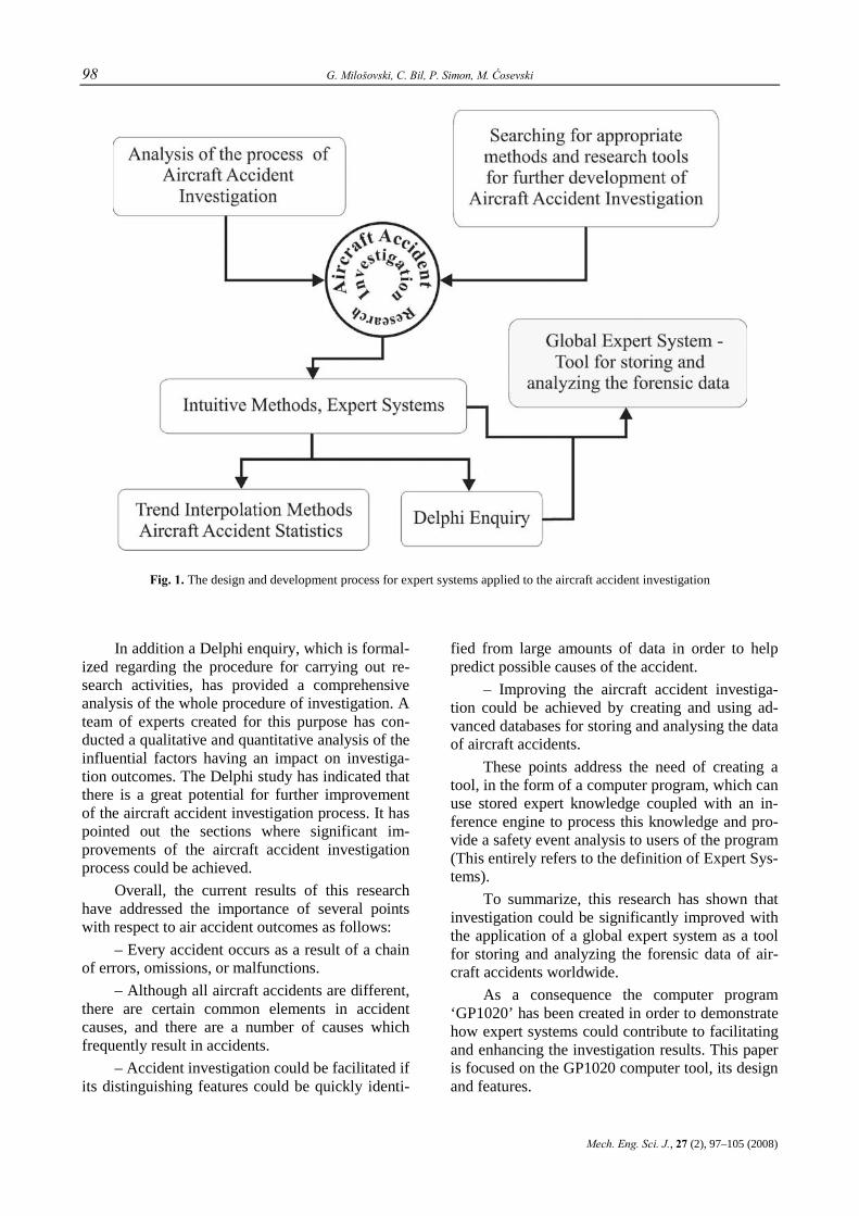
98 G. Milošovski, C. Bil, P. Simon, M. Ćosevski
Mech. Eng. Sci. J., 27 (2), 97–105 (2008)
Fig. 1. The design and development process for expert systems applied to the aircraft accident investigation
In addition a Delphi enquiry, which is formal-ized regarding the procedure for carrying out re-search activities, has provided a comprehensive analysis of the whole procedure of investigation. A team of experts created for this purpose has con-ducted a qualitative and quantitative analysis of the influential factors having an impact on investiga-tion outcomes. The Delphi study has indicated that there is a great potential for further improvement of the aircraft accident investigation process. It has pointed out the sections where significant im-provements of the aircraft accident investigation process could be achieved.
Overall, the current results of this research have addressed the importance of several points with respect to air accident outcomes as follows:
– Every accident occurs as a result of a chain of errors, omissions, or malfunctions.
– Although all aircraft accidents are different, there are certain common elements in accident causes, and there are a number of causes which frequently result in accidents.
– Accident investigation could be facilitated if its distinguishing features could be quickly identi-
fied from large amounts of data in order to help predict possible causes of the accident.
– Improving the aircraft accident investiga-tion could be achieved by creating and using ad-vanced databases for storing and analysing the data of aircraft accidents.
These points address the need of creating a tool, in the form of a computer program, which can use stored expert knowledge coupled with an in-ference engine to process this knowledge and pro-vide a safety event analysis to users of the program (This entirely refers to the definition of Expert Sys-tems).
To summarize, this research has shown that investigation could be significantly improved with the application of a global expert system as a tool for storing and analyzing the forensic data of air-craft accidents worldwide.
As a consequence the computer program ‘GP1020’ has been created in order to demonstrate how expert systems could contribute to facilitating and enhancing the investigation results. This paper is focused on the GP1020 computer tool, its design and features.

Demonstration of expert systems to aircraft accident investigation 99
Ma{. in`. nau~. spis., 27 (2), 97‡105 (2008)
2. EXPERT SYSTEMS TOOL ‘GP1020’
2.1. Expert Systems – Outline
The most common form of an expert system is an interactive computer program that examines data stored and provides a problem solution fol-lowing a set of predefined rules. An expert system involves two principal components: a problem de-pendent set of data stored known as knowledge data and problem independent program known as the inference engine. The interaction between the user and the inference engine is performed via the user interface, which asks questions and supplies the user’s replies to the engine. However, the pos-session of expert knowledge is vital for the suc-cessful application of expert systems.
Users of the program usually see an expert system through an interactive dialog. The dialog is composed of a set of questions whereby conclu-sions are drawn through complex feedbacks. Dia-logs are created from the current information and the content of knowledge base.
In general, the knowledge basis of an expert system contains a large number of ‘if then’ type of clauses that gives the expert systems the ability to use them together to draw conclusions. The knowl-edge that is stored in the expert systems appears in the rulebase, which is composed of four different types of objects such as classes, parameters, proce-dures and rule nodes [7].
Among the many different approaches avail-able to classify a huge amount of data is the widely used method of classification by decision tree in-duction. It constructs a tree in which internal nodes are split as a result of yes/no decisions (Fig. 2).
Q 1?
Q 21 ? Q 22 ?
Q 31 ?
Q m 1? Q m 2? Q m 3? Q m ..? Q m n?
Q 34 ? Q 34 ?Q 32?
C 1 C 2 C 3 C 4 C 5 C 6 C 7 C 8 C 9 C ...
...................................................................................................
Yes N o
Yes N o Yes N o
Yes N o N o N o N o N oYes Yes Yes Yes
YesYes N o N o N o N oYes Yes
Fig. 2. Classification by decision tree induction [7]
2.2. Expert Systems to Aircraft Accident Investigation – GP1020
Using the positive practices of expert systems applications in many fields of science, the com-puter program GP1020, designed for assisting air-craft accident investigation, was created.
Fig. 3. Introduction page of the application GP1020
The user of this program is asked a number of different questions that initially look at the wreck-age and accident site followed by examining the human, aircraft, and weather causal factors. Ac-cording to the answers given, the program will choose the set of most appropriate questions in order to determine the cause(s) of acci-dent/incident. Finally when GP1020 assesses that there is a significant amount of evidence derived it will release the probable cause(s) of this particular safety event.
GP1020 includes two major features: – A forensic approach to the procedure of an
aircraft accident investigation, so that the flow of information, procedures, and the rise of knowledge about the occurrence during a real investigation is also followed by GP1020.
– Being a simple and efficient IT solution in determining the probable cause(s) of an aircraft accident occurrence.
2.2.1. Forensic Approach to an Aircraft Accident/Incident Occurrence within GP1020
The procedure of the GP1020 accident en-quiry follows the steps of a real investigation of an accident/incident occurrence. GP1020 asks a broad range of questions relating to the factual informa-tion and analysis undertaken of a safety event.

100 G. Milošovski, C. Bil, P. Simon, M. Ćosevski
Mech. Eng. Sci. J., 27 (2), 97–105 (2008)
At the initial stages of the data collection the GP1020 program intends to learn general informa-tion about an accident/incident event such as: event type, aircraft type and category, type of flying, and so forth. In addition there are questions which in-tend to ascertain whether the aircraft was flown in visual or instrument meteorological conditions or/and experienced any problems during the flight.
After collecting the general information of a safety event, the GP1020 will strive to learn about aircraft damage, wreckage distribution, witness location, probable flight path, and occurrence of fire or explosion occurred. The GP1020 might ask for information about the person injury category, and cause(s) of death.
The GP1020 using a number of questions ex-amines the human, aircraft, and weather induced causal factors. Thus, GP1020 learns if the crew undertook voluntary acts that are poorly per-formed, failed to act when particular actions were appropriate, or failed to take an immediate action, follow air traffic control instructions, use check-lists, maintain direction control, monitor weather, and/or monitor instrumentation. There are also questions that assess potentially inadequate prepa-ration or supervision, poor judgment, improper use of equipment, alcohol or other drug use, improper maintenance, improper aircraft modifications, and inadequate procedures.
Another set of questions examines the aircraft systems condition and assesses the involvement of those factors as possible cause(s) for the acci-dent/incident. Among them are the questions relat-ing to: wreckage and its systems condition, possi-ble breaking of aircraft limits, readings of instru-ments, data recorders, and emergency procedures carried out.
Next, the GP1020 will ask several more ques-tions designed to consider the weather conditions during the accident. It learns the event temperature, dew point, sky condition and whether the aircraft experienced events like air turbulence, birds strike, volcanic ash, and dust.
2.2.2. Classification of the Causes of Aircraft Accidents within GP1020
The causal factors and their consistent evi-dence within GP1020 are stored and available to the program in several different ways. First of all, the contributory factors are sorted within the three well-known causal factors: human, design and manufacturing, and environmental factors [2].
Secondly, the causes of accidents are additionally sorted in accordance with the nature of accidents: taxiing accidents, takeoff accidents, collisions, tail spins, fires while midair, forced landings, landing, and other accidents [1]. Finally, the list of all pos-sible causes of accidents is classified according to problems that may be experienced during the acci-dent as follows: lift, thrust, flight control, and weather and environmental induced problems, as well as smoke, fire and fumes, explosion, and other problems.
This approach of multiple classifications of causes of accidents within GP1020 allows the crea-tion of a huge and flexible database appropriate for a quick across search. Thus, within GP1020 a large ‘mxn’ matrix has been created, where ‘m’ represents the number of all possible causes of accident (rows) and ‘n’ represents the number of different portions of evidence that may be recovered during an inves-tigation (columns).
T a b l e 1
A list of possible causes of accident versus their distinguishing features
Distinguishing features Evidence
List of all possible causes 1 2 3 4 5 6 .
Cause 1 x X x Cause 2 x x X Human factors
… X x Cause 1 x x x Cause 2 x x
Design and manufacturing factors … x X x
Cause 1 x x Cause 2 x x
Environmental factors
… .
The matrix above has been converted into an-other format, shown below in Figure 4, which is appropriate to the needs of the GP1020 program [4, p. 238}.
Each column of the matrix, which represents a different portion of evidence, must be associated with a question. This means that GP1020 is com-posed of a large number of questions similar to the number of distinguishing features of all possible causes of accidents.
The second table of Figure 4 shows how GP1020 may ask the user questions in order to de-termine the cause(s) of accident/incident. For in-

Demonstration of expert systems to aircraft accident investigation 101
Ma{. in`. nau~. spis., 27 (2), 97‡105 (2008)
stance (in the case presented in Figure 4) if GP1020 asks the question associated with E5 (or QE5) then a positive answer provided by user will automatically finish the procedure as only the ‘Cause 4’ includes evidence E5. On the other hand if GP1020 asks the QE1 and the user provides a positive answer to it then the program will generate further questions related to C4, C8, C2, C1, and C7 that include this evidence, and so on.
E1 E2 E3 E4 E5 E6
C1 x x x C2 x x x C3 x x C4 x x X C5 x x C6 x x x C7 x x C8 x x
E5 E3 E1 E4 E6 E2
C4 x x x C8 x x C2 x x x C1 x x X C7 x X C3 x X C6 x X x C5 X x
Fig. 4. Conversion of the original matrix into the GP1020 format C1, C2 … C8 – an assumed list of 8 possible causes of accident. E1, E2 …E6 – consistent portions of evidence
(accidentally chosen) to the above causes.
2.2.3. Expert knowledge stored in the GP1020
The first condition for the successful applica-tion of an expert system in any scientific field is the amount of specific expert knowledge stored. While the authors of this paper were attempting to solve this task, the conclusion emerged that creat-ing a comprehensive database of causes for acci-dents and their distinguishing features is far be-yond an individual or a small group capacity. Therefore, authors decided that the NTSB aviation accident database as stored expert knowledge is an excellent resource available for accomplishing the
task of creating an expert system for the aircraft accident investigation (suggested in [6, p-p. 8, 168]).
The NTSB aviation accident database is available on the NTSB’s web site (ftp://www.ntsb. gov/avdata/), which contains highly classified and downloadable datasets of more than 140,000 avia-tion accidents. The computerized findings are iden-tified in a sequence of events as occurrences, phases, causes, factors, and/or events. The existing code system includes 51 phase codes, 54 occur-rence codes, 1593 probable cause subject codes, 422 probable cause modifier codes, 52 probable cause person codes. This code system indicates how thoroughly the accidents are classified thus making the resource a potentially great base of ex-pert knowledge for the GP1020 program.
2.3.4. GP1020 Prototype
The GP1020 is a program that can effectively compare and analyze the causes and factors of an immense number of previous aviation incidents and accidents in order to predict and prevent future accidents or to hasten air crash investigation ef-forts. It is assumed that the amount of historical data stored regarding aviation incidents and acci-dents is sufficient to provide such an analysis.
The current version of the GP1020 software was to act as a prototype purely to test some of the fundamental mechanisms required by components of the expert system methodology. Thus, a basic version of a knowledge base, inference engine and user interface had to be developed in order to fur-ther understand the required interaction between each component of the program.
Programming Software. The use of Excel to develop this software turned out to be the most appropriate choice for the GP1020. It had been built in commands for data mining, sorting, statis-tical analysis and linguistics analysis. It also has numerous accuracy checks to ensure that any cell formulae and scripts are as correct as possible. Es-sentially it allowed focus on the development of the fundamental logic over any of the program code required for allowing application execution in any specific operating system. It also avoided the entire issue regarding how to insert the historical data into the program as Excel is already capable of handling numerous table data formats. About the only thing it may, and apparently did, lack is effi-ciency in terms of computation speed. Throghout the development of the GP1020 prototype this rela-

102 G. Milošovski, C. Bil, P. Simon, M. Ćosevski
Mech. Eng. Sci. J., 27 (2), 97–105 (2008)
tively high level of inefficiency was the most preva-lent limiting factor to the prototype capabilities.
Knowledge Base. Originally it was hoped to develop a program that could interface with raw historical data and be ready for questions moments after the integration. However, it was apparent early that a separate program would be needed to alter the historical data records into a form that the inference engine could use.
The simplest, and therefore currently ideal, form for the knowledge base to suit the comparative programming that the GP1020 uses would be as a table where each investigation or case is represented by a single row, with consistently occurring types of information represented by various columns.
As this prototype is fairly basic, the only his-torical data that was really needed to create a fun-damental program was some generic information to easily identify the case as well as the causes and factors pertaining to the case (sequence of events, occurrences, flight phases, subjects and modifiers).
In future, when the program operating envi-ronment is known, the inefficiencies given by Ex-cel should be largely reduced when the fundamen-tal logic in the knowledge base preprocessing is transferred or altered to suit the environment cho-sen operating system or program. At the very least, the data limitations of the knowledge base and its preprocessor should grow parallel to the increase in computing power that will probably become available to it. Given that the program was com-puted on a personal computer, increasing the knowledge base to include all forms of relevant recorded data should be fairly feasible.
User Interface. The creation of the user inter-face was the last to be initiated. As a fundamental program, only the basics were required; the ability to ask questions, the ability to receive questions and the ability to display cases that bear the most resemblance to the case currently being investi-gated. It would have been a very large task had not the NTSB database already made numerical desig-nations for occurrences, flight phases, subjects and their modifiers. Also, all the important decisions regarding the relative positions of all the cases and all possible questions were determined by the in-ference engine, so the user interface only had to interact with the inference engine in terms of input-ting answers and displaying results.
The decision to show multiple similar cases as opposed to showing only the most similar case was a product of practicality from two perspectives the user and the program developer. As a program
developer, there is a need to see how the displayed result evolves, or is calculated, to ensure that the appropriate functions are occurring. Constant checking of the top 20 results has heavily assisted in making sure formulae and calculations were per-forming accurately. From the user’s perspective there was an obvious requirement, that one lone case record could hardly be expected to meet the user’s information needs. While the most similar case to the user’s investigation could well be en-tirely useful to the user’s investigation, unless it is exactly the same, the most similar case could not fully assist the user in understanding his or her in-vestigation. It would be more likely that the se-quence of events that the user is trying to establish in his or her investigation could be derived from the combination of events from two or more differ-ent historical records. Essentially, the more rele-vant historical records are available to the user, the better off the user should be.
The details shown in the 20 most similar cases are its event ID (a unique numeric code des-ignation for the incident/accident), date, aircraft make, operator’s name, departure location and des-tination location. These details effectively tell who was flying what where when and where to. The only other detail shown is the “Level of Relevancy” which indicates the proportionate number of ques-tions (and therefore answers) that positively match the case shown against the total number of questions asked.
Inference Engine. When discussing the in-ference engine, the entire capability of the program is dependant on its ability to use causes and factors determined in previous investigations to predict future investigations. So essentially a likely se-quence of events for the user’s investigation is cre-ated from a) the user’s answers, and b) the prob-abilities those answers imply.
Basically the main concept to be used in the program is that causes and factors have relationships that can be defined by verifiable statistics.
The current method used in the program util-izes exact match data mining. Given a partial se-quence of event data (question answers), the en-gine calculates a score for each historical case in-dicating the number of exact matches between its events and the events contained within the partial data. Positive matches increase the case’s score, negative matches decrease it.
Cases are then ranked according to this score and the events from cases above a certain rank are collected and their frequency in that collection de-

Demonstration of expert systems to aircraft accident investigation 103
Ma{. in`. nau~. spis., 27 (2), 97‡105 (2008)
termined. The next question that is asked by the user asks whether or not the event with the highest frequency had occurred. From here, further ques-tions are asked regarding other highly frequent possibilities.
Questioning ceases when a significant amount of variations occurs between the levels of rele-vancy between the cases displayed.
The next level of computation to be imple-mented, given more processing power, is more rep-resentative of the work done in the previous sec-tion of this paper (refer to Table 1 and Figure 4). It improves the case score calculation by also consid-ering matches with events statistically related to the partial data, and not just the events within the partial data alone. It would effectively increase the rate of relevancy variation significantly.
2.2.5. GP1020 Prototype – User Instructions
User instructions are given on the introduc-tion page of the program. By clicking on the
spreadsheet titled “Query Page” the process be-gins.
On the sheet titled "Query Page", two distinct sections will appear; the one at the top shows the top 20 cases most likely to resemble, and thus be used as a reference in understanding, the case that the user is currently investigating. The one at the bottom shows the questions that the software would ask depending on the data given.
To begin using the software, answers of the two questions already shown in the bottom must be provided. It is done by clicking the yellow box next to each question and choosing an appropriate answer from the drop down menu.
Soon after, a third question should appear. Similarly, it is answered by clicking the yellow cell next to the question and choosing an answer from the drop down menu. Consequently the top 20 most similar cases will be displayed on the top box and a fourth question should appear in the bottom box (Fig. 7).
Fig. 5. GP1020 Prototype – Query Page

104 G. Milošovski, C. Bil, P. Simon, M. Ćosevski
Mech. Eng. Sci. J., 27 (2), 97–105 (2008)
Fig. 6. GP1020 Prototype – Drop Down Menu
Fig. 7. GP1020 Prototype – Fourth Question

Demonstration of expert systems to aircraft accident investigation 105
Ma{. in`. nau~. spis., 27 (2), 97‡105 (2008)
Software user continues answering questions till the Relevancy column (the one in green) begins to show different values. From here, two choices become available; either start to use the top 20 cases to gain understanding on your case, or answer more questions to increase the Relevancy or to cause further differences in Relevancy. Ideally, with an increasing amount of variation in Rele-vancy, the 20 cases shown should become more suited to assist understanding of the case being ana-lyzed.
3. CONCLUSION
The research results presented in this paper have shown that expert systems methodology is an appropriate approach in analyzing the aircraft acci-dent investigation process. Thus the novel GP1020 investigation tool has been a successful demonstra-tion of applying an expert system concept to the aircraft accident investigation. The GP1020 has been designed to give aircraft accident investigators improved use of forensic data by sifting through a considerable amount of data related to accidents and to indicate the most probable accident cause(s).
Results obtained during the testing of the GP1020 program encourage the application of a
global expert system, or in other words, increase the program’s knowledge pool to include historical data from many other sources other than those currently being used. In terms of computer power limitation, either changing code to suit a particular operating system or utilizing hardware with greater comput-ing power would overwhelm this problem.
REFERENCES
[1] Ames J. S.: "Aircraft accidents: Method of Analysis" in Seventeenth Safety Congress, Passenger Safety, Washing-ton. p. 760–772, (1928/1984).
[2] CETS: Improving the continued airworthiness of civil air-craft, A strategy for the FAA's aircraft certification ser-vice. National Press, Washington (1998).
[3] ICAO: Aircraft accident and incident Investigation: inter-national standards and recommended practices, annex 13 to the Convention on International Civil Aviation. ICAO: Montreal. (2001).
[4] Miyagi M.: Serious accident and human factors. John Wiley & Sons Ltd: West Sussex (2005).
[5] NTSB: Transportation safety database. NTSB: Washing-ton. (www.ntsb.gov/avdata) (2002)..
[6] Wood R., Sweginnis R.: Aircraft accident investigation. Endeavour Books: WY (1995).
[7] Zhu X., Davidson I.: Knowledge discovery and data min-ing. Information Science Ref: Hershey (2007).
R e z i m e
EKSPERTSKI SISTEM ZA ISTRAGA NA AVIONSKI NEZGODI
Goran Milo{ovski, Cees Bil, Paul Simon
School of Aerospace, Mechanical, and Manufacturing Engineering, RMIT University, Melbourne, Australia
[email protected] // [email protected] // [email protected]
Klu~ni zborovi: ekspertski sistemi; istraga na avionska nezgoda
Rezultat od proektot ‘Podobruvawe na istra-gata na avionska nezgoda’ sproveden na Ma{inskiot fakultet pri Royal Melbourne Institute of Technology vo Melburn, Avstralija, vo sorabotka so Ma{inskiot fakultet pri Univerzitetot „Sv. Kiril i Metodij” vo Skopje, e originalna istra`uva~ka alatka nare-~ena GP1020. Programata GP1020 so primena na meto-dot data mining e dizajnirana efektivno da gi koristi skladiranite podatoci od prethodnite avionski nez-godi za potrebite od tekovni istragi na avionski nezgodi. Kompjuterskata alatka GP1020 e sposobna za
kratko vreme da gi prebara istoriskite podatoci od avionski nezgodi vo pogled na pri~inskite faktori i soodvetno izvedenite dokazi. Programata GP1020 postavuva pogolem broj pra{awa koi se odnesuvaat na sostojbata na letaloto, mestoto na nezgodata i drugi posledici relevantni za nezgodata koja se analizira. Odgovaraj}i na pra{awata, programata e sposobna da ja namali listata na mo`nite pri~ini za nezgoda i kone~no da ja prika`e najverojatnata pri~ina za ana-liziranata avionska nezgoda.

Mechanical Engineering – Scientific Journal, Vol. 27, No. 2, pp. 107–112 (2008) CODEN: MINSC5 – 398 ISSN 1857–5293 Received: September 9, 2008 UDK: 543.275.1 Accepted: September 20, 2008
Original scientific paper
HUMIDITY LEVEL IN PSYCHROMETRIC PROCESSES
Filip Mojsovski
Faculty of Mechanical Engineering, ”SS. Cyril and Methodius” University, P.O. Box 464, 1000 Skopje, Republic of Macedonia
A b s t r a c t: When a thermal engineer needs to control, rather than merely moderate humidity, he must focus on the moisture level as a separate variable – not simply an addition of temperature control. Controlling humidity generally de-mands a correct psychrometric approach dedicated to that purpose [1].
Analysis of the humidity level in psychrometric thermal processes leads to relevant data for theory and practice [2].
This paper presents: (1) the summer climatic curve for the Skopje region, (2) selected results of investigation on farm dryers made outside laboratories.
The first purpose of such activity was to examine rela-tions between weather conditions and drying conditions. The estimation of weather condition for the warmest season of the year was realized by a summer climatic curve. In the science of drying, basic drying conditions are temperature, relative humidity and velocity of air, thickness of dried product and dryer construction.
The second purpose was to realize correct prediction of drying rates for various psychrometrics drying processes and local products.
Test runs with the dryer were carried out over a period of 24 h, using fruits and vegetables as experimental material. Air flow rate through the dryer of 150 m3/h, overall drying rate of 0.04 kg/h and air temperature of 65 oC were reached.
Three types of solar dryers, were exploited in the re-search.
Key words: psychrometric processes; climatic curve; natural air convection; farm dryer, tomato; raspberry
1. INTRODUCTION
For thermal engineers two fluids are basic, air and water.
In thermodynamics the term air is used as at-mospheric air, dry air and moist air.
Psychrometrics is a science dealing with the properties and processes of moist air.
Moist air is a binary mixture of dry air and water vapor. By definition dry air exists when all water vapor and contaminants have been removed from atmospheric air. Extensive measurements have shown that the composition of dry air is rela-tively constant but small variations do occur with time, geographical location and altitude [3]. In psychrometric processes dry air is treated as a sin-gle entity.
The amount of water vapor in moist air is variable, ranging from nearly zero (dry air) to a maximum (characteristically from 0.0000363 to 0.00907 kg of water vapor per kg of dry air under surface atmospheric conditions) depending upon temperature and pressure.
Therefore, to estimate the change of water vapor amount in moist air, or the humidity level, means to estimate the moist air psychrometric state.
The psychrometric state of a mixture of dry air and water vapor is fixed when the values of three independent properties are known, (1) baro-metric pressure or altitude, (2) dry-bulb tempera-ture, and either (3a) wet-bulb temperature, (3b) relative humidity, or (3c) dew-point temperature.
A psychrometric process happens when air at an initial state undergoes a transformation and ends up at a final state. The transformation involves the transfer to or from the air of: (1) heat, (2) mass (mostly water vapor).
The four basic psychrometric processes are: sensible heating, sensible cooling, humidification, dehumidification.
On a psychrometric shirt, the sensible heating process advances horizontally to the right along a

108 F. Mojsovski
Mech. Eng. Sci. J., 27 (2), 107–112 (2008)
line of constant humidity ratio. The final state point has higher dry-bulb temperature, higher wet-bulb temperature, lower relative humidity, and constant humidity ratio.
The transfer of heat into air using a hot water coil is an example of this process.
On a psychometric shirt, the sensible cooling process advances horizontally to the left along a line of constant humidity ratio. The final state point has lower dry-bulb temperature, a lower wet-bulb temperature, higher relative humidity, and constant humidity ratio.
The transfer of heat from air using chilled wa-ter or refrigerant cooling coil is an example of this process.
A large number of psychrometric processes in the practice can be represented by the four basic processes or by their modifications with simulta-neous heat and mass transfer.
One of them, drying of agricultural products is becoming more and more an alternative to mar-keting fresh fruits and vegetables, since the de-mand for high quality dried food is permanently increasing all over the world.
In Macedonia, inadequate conservation and storage facilities and lacking marketing structure lead to the spoilage of large quantities of agricul-tural produce. To overcome the existing preserva-tion problem, the introduction of solar dryers seems to be a promising solution. Furthermore, all criterions for real success in solar farm dryer use, are satisfied: (1) high solar radiation, (2) low quan-tities to be dried, (3) lack of energy.
The design and continuous operation of the solar dryer as the design of the energy system for any thermal device has a direct impact on the cost of operating a plant and an indirect impact on the environment.
Although the procedures for calculating en-ergy requirements vary considerably in their de-gree of complexity, they all depend on local cli-matic conditions.
The first step in every method for estimating energy use is to insure correct climatic information.
This information, which includes climatic curves, dry-bulb temperature, wet-bulb tempera-ture, typical weather year, wind speed, is influ-enced by the state in atmosphere.
In recent years, more and more attention has been paid to the systematic study of the fine struc-ture of the atmospheric processes and especially to
the detailed study of phenomena which occur in the layers of the air nearest the ground.
Climatic curves represent the behavior of the atmospheric air [4]. At least two properties of moist air must be known to determine the remain-ing characteristics. The air temperature and relative humidity are the needed properties for estimation of moist air states by climatic curves.
Atmospheric air states in the Skopje region for the period of one year or only summer period are estimated by a dirct analysis of hourly air rela-tive humidity and temperature long term observa-tions [5]. The summer climatic curve, for the Skopje region, indicates the change of temperature between 20 and 40oC, humidity ratio between 8 and 10 g/kg, relative humidity between 20 and 60 % (Fig. 1).
2. PSYCHROMETRIC APPROACH IN AGRICULTURAL ENGINEERING
Most agricultural products must be dried to, and maintained at a suitable, moisture content, by using natural or forced air convection.
A particular dryer and product may dictate a specific relative humidity, a required range of rela-tive humidity, or certain limiting maximum or minimum values.
Three types of dryers were under investiga-tion [5]:
1. Farm dryer with rock-bed heat storage, FD-SA (Fig. 2).
2. Farm dryer with water-bed heat storage, FD-WA (Fig. 3).
3. Farm dryer with an auxiliary heating sys-tem, FD-99 (Fig. 4).
The dryer FD-SA, without chimneys has di-mensions length × width × height = 3770 × 6400 × 2720 mm, one air inlet at level 420 mm, four air outlets at level 5000 mm. The floor is constructed as heat storage reservoir of 20 m3 blocks of stone. Capacity of the working surface is 15 m2.
The dryer FD-WA, without chimney has di-mensions length × width × height = 3000 × 2000 × 1850 mm, one air inlet at level 100 mm, one air outlet at level 3900 mm. The dryer has a modular heat exchanger. Eight metallic elements contain 1 m3 water. Capacity of the working surface is 4 m2.
The dryer FD-99 has dimensions length × width × height = 3500 × 1000 × 3350 mm, one air

Humidity level in psychrometric processes 109
Ma{. in`. nau~. spis., 27 (2), 107‡112 (2008)
inlet at level 100 mm, one air outlet at level 3300 mm. Capacity of the working surface is 1 m2.
Dryers FD-SA and FD-WA are imported, with small reconstructions made in the stage of montage.
The dryer FD-99 is designed and produced in Skopje, as a prototype version [6], and two im-proved versions [5].
Fig. 1. Summer climatic curve for town Skopje

110 F. Mojsovski
Mech. Eng. Sci. J., 27 (2), 107–112 (2008)
Fig. 2. Farm dryer with rock-bed storage, FD-SA
Fig. 3. Far dryer with water-bed heat storage, FD-WA
Fig. 4. Farm dryer FD-99

Humidity level in psychrometric processes 111
Ma{. in`. nau~. spis., 27 (2), 107‡112 (2008)
3. FIELDWORK WITH FARM DRYERS
During the last decade research in solar dry-ing of fruits and vegetables has gained consider-able activity in Macedonia.
Team of researchers from two faculties, Fac-ulty of Mechanical Engineering and Faculty of Ag-ricultural Sciences and Food, have been involved in drying of vegetables since 2000, and drying of fruits since 2005.
Vegetable representatives were: tomato, pa-prika, carrot, potato, parsley, onion, garlic.
Fruit representatives were: apple, apricot, fig, plum, pear, banana, raspberry…
With donations from Germany and Holland, most of the effort was put on the hardware parts of the dryers.
Garman investment contained three steps: (1) Visit to seven faculties of agriculture in Germany, (2) Purchase of dryers, (3) Seminar for tomato dry-ing. Those activities were arranged by GTZ (Ger-man Technical Cooperation).
In 2000, by investment in prototype series of seven dryers, Dutch obtained a good start of their project for solar drying of tomatoes.
Up to now, eight years field measurements at seven locations across Macedonia were carried out.
The collected results and the proposed im-provement for dryer functioning are partially pub-lished [7].
Applied drying conditions were based on mathematical modeling of the drying process by natural convection, own experience in fieldwork with dryers and continuous improvement of dryers construction.
The auxiliary heating system operated with rock-bed heat storage, water-bed heat storage and gas.
The drying progress was recorded by measur-ing th product weight every 30 min.
Temperature, relative humidity and air veloc-ity were recorded during the whole drying cycle.
The level of the humidity reached in the field-work with solar dryers is represented in Table 1.
T a b l e 1
Drying of tomatoes and raspberry – humidity level
Tomatoes Raspberry
Initial moisture content, wet basis, % 85 – 95 60 – 70
Final moisture content, wet basis, % 8 – 10 10 – 15
Initial air temperature, oC 40 – 50 40 – 50
Final air temperature, oC 60 – 70 55 – 65
State, 1 – peace, 2 – whole product 1 2
From [5]
4. CONCLUSIONS
4.1. Summer climatic curve for the Skopje re-gion, prepared with hourly observations for period of fifteen years has been published.
4.2. Humidity level data for drying of toma-toes and raspberry, obtained from own fieldwork, have been proposed.
4.3. Data from climatic curve (Fig. 1), humid-ity level (Tab. 1) and equilibrium moisture content curves for dried product provide correct represen-tation of drying process in the psychrometric shirt.
REFERENCES
[1] Harriman L., Brundrett G., Kittler R.: Humidity Control Design Guide, American Society of Heating, Refrigerat-ing and Air-Conditioning Engineers, Atlanta, U.S.A., 2001.
[2] Gatley D.: Understanding Psychrometrics, Second edi-tion, American Society of Heating, Refrigerating and Air-Conditioning Engineers, Atlanta, U.S.A., 2005.
[3] Olivieri J., Singh T.: Psychrometrics – Theory and Prac-tice, American Society of Heating, Refrigerating and Air-Conditioning Engineers, Research Project 872-RP, At-lanta, U.S.A., 1996.
[4] Mojsovski A., Poredoš A.: Climatic curves, Proceedings of the Second Annual Conference of Slovenian Associa-tion for District Energy, p. 67–73, Portorož, Slovenia, 1999.
[5] Mojsovski F.: Analysis of humidity level in psychrometric thermal processes, Ph D thesis, (In Macedonian), Skopje, Macedonia, 2007.
[6] Mojsovski F., Mojsovski A., Martinovski Gj., Popsi-monova G., Katažina-Petrevska J.: Farm Dryer FD-99-1, Proceedings, Faculty of Mechanical Engineering, Skopje, Republic of Macedonia, Vol. 19., No. 2., pp. 125–128, 2000 (in Macedonian).
[7] Mojsovski A., Martinovski Gj., Mojsovski F.: Low tem-perature drying, Proceedings of the Tenth Meeting “Ma-cedonian Society of Thermal Engineers ‘08”, Bitola, Re-public of Macedonia, pp. 53–62 (2006) (in Macedonian).

112 F. Mojsovski
Mech. Eng. Sci. J., 27 (2), 107–112 (2008)
R e z i m e
NIVO NA VLAGATA VO PSIHROMETRISKI PROCESI
Filip Mojsovski
Ma{inski fakultet, Univerzitet „Sv. Kiril i Metodij“, p. fah 464, MK-1001 Skopje, Republika Makedonija
Klu~ni zborovi: psihrometriski procesi; klimatska kriva; prirodna konvekcija; mala su{ilnica; domati; malini
Koga termi~arot ima potreba precizno da ja kontrolira vlagata, toj treba nejzinito nivo da go smeta za posebna promenliva, a ne kako dopolnitelen rezultat od kontrolata na temperaturata. Op{to ka`ano, da se kontrolira vlagata zna~i da se primeni pravilen psihrometriski priod [1].
Bitni podatoci za teorijata i praktikata se dobivaat preku analiza na nivoto na vlagata vo psi-hrometriski termi~ki procesi [2].
Statijava nudi: (1) klimatska kriva na Skopje za letniot period, (2) odbrani podatoci od termi~kite istra`uvawa na mali su{ilnici.
Najva`no be{e da se ispita odnosot pome|u kli-matskite uslovi i uslovite na su{ewe. Preku kli-matskata kriva za letniot period bea proceneti kli-
matskite uslovi. Vo naukata za su{ewe, pod uslovi na su{ewe se podrazbiraat: temperaturata, relativnata vla`nost i brzinata na strueweto na vozduhot, debe-linata na slojot od materijalot {to se su{i i kon-struktivnite karakteristiki na su{ilnicata.
Sledna zada~a be{e da se realizira pravilno pretska`uvawe na postignatoto su{ewe, za razli~ni psihrometriski procesi i lokalni proizvodi.
Ispituvawata se odvivaa kontinuirano, na ovo{je i zelen~uk. Postignato be{e struewe na vozduhot od 150 m3/h, vkupno odzemena vlaga 0,04 kg/h i tempera-tura na vozduhot 65 oS.
Istra`uvawata bea sprovedeni na tri konstruk-cii na su{ilnici {to koristat energija od Sonceto.
Mechanical Engineering – Scientific Journal, Vol. 27, No. 2, pp. 113–121 (2008) CODEN: MINSC5 – 399 ISSN 1857–5293 Received: May 23, 2008 UDK: 004.93 Accepted: June 26, 2008
Original scientific paper
METAL LABEL CHARACTER RECOGNITION
Chang-Hou Lu1, Guo-Liang Lu1, Zhu-Yan Xu1, Huai-Bo Song1, Zoran Pandilov2 1School of Mechanical Engineering, Shandong University,
Jinan, 250061, P. R. China 2Faculty of Mechanical Engineering, “SS. Cyril and Methodius” University,
P. O. Box 464, MK-1001 Skopje, Republic of Macedonia [email protected]
A b s t r a c t: The metal label character recognition (MLCR) system aims to realize the recognition of characters printed on the metal label. Due to the capturing conditions and characteristics of the metal label, as well as the existing simi-lar characters such as ‘1’and ‘/’, ‘0’ and ‘D’, the metal label characters are hard to be recognized. This paper presents a method of illumination compensation to improve the quality of metal label characters and multiple classifiers based on improved circumference projection by artificial neural net-work to achieve a high recognition rate. Experiments show this method has a high recognition rate and needs less time, which is feasible for a practical application.
Key words: metal label characters; circumference projection; radical moments; similar character recognition
1. INTRODUCTION
The metal label is an indispensable and im-portant symbol in the steel products. It represents the information, such as the performance, the spe-cification, the type, the weight, the national stan-dard and the date of production [1]. This informa-tion can be divided into two parts: the changeless part and dynamic part as shown in Fig. 3(b).
The recognition of the dynamic part is impor-tant for the information-based management of in-dustry. The subject has been receiving consider-able attention in recent years due to the increased demand on digital data and the construction of the Enterprise information system. Several methods for recognition of numbers, letters, Chinese, Latin and other characters have been proposed [2–5]. This research area is still hot and demanding. Metal label characters are consisted of all the num-bers from 0–9, some uppercase and some special
signs. And what’s more is, other character recogni-tion researches focus on the high-quality digit im-age in which the character and the background are of different colors or a great chromatism, while the characters pressed on the metal label have distinct features:
(1) The characters are protruded and the char-acter and the background are of the same material, so the color of them are almost the same.
(2) The image is formed by the difference of reflectance, so the character itself has a great gray scale difference.
(3) After the step of binarization in pre-processing, some binary characters deform greatly, sometimes misshappen.
Researches concerned with metal label char-acters recognition have been described in literature [6–20]. These techniques are applied for the MLCR system. Despite of so many different approaches proposed, their performance still needs to be im-proved, such as the large capture-implement and low recognition rate. So, it is necessary to research further on how to capture the high-quality metal label image, image pre-processing, feature extrac-tion and recognition of metal label characters.
In this paper we propose a MLCR combining statistical and structural method. The outline of this paper is organized as it follows: the next section introduces the flow of our metal label character recognition. Section 3 introduces the image-capture implement briefly. Section 4 introduces the image pre-processing method. Section 5 explores the improved radical moments and similar charac-ters recognition. Section 6 describes performance

114 C.-H. Lu, G.-L. Lu, Z.-Y. Xu, H-B. Song, Z. Pandilov
Mech. Eng. Sci. J., 27 (2), 113–121 (2008)
of our MLCR system. Section 7 concludes the pa-per and gives some future work.
2. OVERVIEW OF THE MLCR SYSTEM
In a MLCR system, each step plays an impor-tant role for a high-performance system. This paper
analyzes the characteristic of metal label characters and expatiates the preprocessing and recognition steps. Fig. 1 gives the flow of our metal label char-acter. It recognizes metal label characters by mul-tiple classifiers. In the step of similar characters recognition, we use branch-classifiers which can recognize the similar metal label characters in one set as shown in Table 1.
Metal label image capture
Image Pre-processing
Radical momentsextraction
Recognition by ANN
Output
Structural features extraction
Similar characters classifiers
Fig. 1. Flow of our metal label character recognition
T a b l e 1
Sets of similar characters
Sets of similar metal label characters
Set 1 1 I — / Set 5 7 L J Set 2 6 9 Set 6 0 D Q Set 3 8 B Set 7 W M Set 4 X ×
3. IMAGE-CAPTURE DEVICE
Usually, the image of the OCR system is cap-tured by CCD directly. But for the characteristic of the metal label discussed in the introduction, it is necessary to find an appropriate way to capture the metal label image. The CCS light source, the in-strument which is based on the principle of optics,
is special for application of machine vision, and it can improve the quality of images captured in the machine vision systems. Our image-capture device is based on the CCS ring-shaped light source. Ar-chitecture of this implement is shown in Fig. 2. Fig. 3 shows the result image captured by CCD directly and our implement.
Fig. 2. Flow of our image-capture implement
(a) (b) Fig. 3. Image captured: (a) captured by CCD directly, (b) captured by our implement

Metal label character recognition 115
Ma{. in`. nau~. spis., 27 (2), 113‡121 (2008)
4. PRE-PROCESSING
Because the metal label is captured under practical condition, natural lighting affects the quality of the image. Therefore the characters seg-mented vary in brightness, and this problem affects the recognition rate. So it is necessary to process the character before feature extraction.
4.1. Segment characters from the metal label image
The incised label characters are pressed by a printer. In the process of pressing, the location of characters is according to the format of the metal label. So we can segment the incised characters with mask matching. Fig. 4 shows this method.
(a)
(b)
Fig. 4. (a) Segment incised characters with mask matching, (b) Junior-segmented characters
4.2. Illumination compensation
4.2.1. Character Area Segmentation
As Fig. 5 (a1), (a2), (a3) shows, there are three character images that have different illumina-tion. (b1), (b2), (b3) are the edge binary images by the Canny detector. It indicates that the complete edge can be detected by the Canny detector only from the high-quality image. The detected edges form the low-quality image are unsteady, therefore feature extraction based on the edge is unreliable. But it can be seen that the Canny detector has a good ability of area-location, and we can segment the character area with the edge binary image by the Canny detector. (c1), (c2), (c3) show the result images.
(a1) (a2) (a3)
(b1) (b2) (b3)
(c1) (c2) (c3)
Fig. 5. (a1)–(a3): Junior-segmented characters. (b1)–(b3): Binary image detected by the Canny detector.
(c1)–(c3): Result images
4.2.2. Subsection non-linear gray transformation
The general gray transformation can be di-vided into three classes: linear transformation, sub-section linear transformation and non-linear trans-formation (see Fig. 6: The horizontal coordinate expresses the input gray and the vertical coordinate expresses the output gray).
(a) Linear transformation
(b) Subsection transformation
(c) Non-linear transformation
Fig. 6. Three classes of gray transformation

116 C.-H. Lu, G.-L. Lu, Z.-Y. Xu, H-B. Song, Z. Pandilov
Mech. Eng. Sci. J., 27 (2), 113–121 (2008)
In this paper, we propose a subsection non-linear gray transformation that combines the non-linear transformation with the subsection transfor-mation.
4.2.2.1. Decision of cut-off points
Seeing Fig. 5. (c1)–(c3), although the charac-ter area is segmented, there are still some noises and some noises are too bright, some noises are too dark. If we don’t check and wipe off these noises, these will affect the visual effect of the image processed greatly.
Say the brightness value of one image pixel is ( , )f x y , the total pixels is N and the grayscale is L ( L = 256 in this paper). The brightness value of the Kth grayscale is kr , and kn denotes the total pixels whose brightness value is kr . So the prob-ability of the Kth grayscale is ( )r kp r :
( ) / ,1 255r k kp r n N k= ≤ ≤ . (1)
The gray value of the background is 0, so it needs not to be counted.
Set
1 1
( ),k k
k r i k ii i
s p r m n= =
= =∑ ∑ . (2)
When %5<ks , %51 >+ks and km > Q, the Kth grayscale A is the 1st cut-off point. Q is a statistical value that is set according to the size of the character area.
When %95<ks , %951 >+ks and km >Q, the Kth grayscale B is the 2nd cut-off point. Figure 7 shows the sample of decision of the cut-off point.
Fig. 7. The sample of decision of the cut-off point
4.2.2.2. Non-linear gray transformation
According to the two cut-off points, the char-acter gray histogram can be divided into three sec-tions: dark section, middle section and light section.
To the dark section, set the gray value in this section to the maximum gray value LG .
To the light section, set the gray value in this section to the minimum gray value OG .
To the middle section, based on the human eye response curve, we the select the Log-Function as the non-linear transformation model. The spe-cific transformation is as following:
( , ) [ln ( , ) ln ]ln ln
L OO
G Gg x y f x y m Gn m−
= − +−
. (3)
In the above equalization 3, ( , )g x y is the output image, ),( yxf is the input image, m and n are the min and max gray values of the input image, and ,L OG G are the max and min gray values of the output image.
Above all, the following shows us the con-crete transformation in our approach, and the fig-ure shows the result image after the illumination compensation.
[ln ( , ) ln ] , ( , )ln ln
( , ) , ( , ), ( , )
L OO
O
L
G G f x y m G A f x y Bn m
g x y G f x y AG f x y B
−⎧ − + ≤ ≤⎪ −⎪= <⎨⎪ >⎪⎩
(4)
Fig. 8. Subsection non-linear transformation
(a) (b) (c)
Fig. 9. The result image
4.3. Character Binarization
After the illumination compensation, the character images have similar illumination inten-sity. There are many approaches for character bi-narization. In this paper, we select Otsu binariza-tion based on the Maximum Variance Theory.

Metal label character recognition 117
Ma{. in`. nau~. spis., 27 (2), 113‡121 (2008)
(a) (b) (c)
Fig. 10. The binary character by the Otsu binarization
5. IMPROVED CIRCUMFERENCE PROJECTION AND FEATURE EXTRACTION
The original circumference projection uses the center of mass (abbreviated to ‘m-c’) as a pro-jection center for the rotation invariance. But ac-cording to the metal label characters’ characteris-tics indicated before, the projection center based on m-c is not reliable in original circumference. So, we propose the improved circumference projection as the following:
5.1. Normalization of processed characters
5.1.1. Size normalization
Characters segmented from the different metal label have different sizes. A linear normali-zation algorithm is applied to the input image to adjust to a uniform size (in our implementation, 45×32). Assume the horizontal and vertical projec-tions of the original image be H andV , respec-tively. The normalization position ),( nm of ),( ji is obtained by:
∑∑=
=
×=i
kI
kkH
MkHm1
1)(
)( , (5)
∑∑=
=
×=j
kJ
kkV
NkVn1
1)(
)( , (6)
Where NM , is the height and width of the normalized image.
5.1.2. Coordinate normalization
Ali Broumandnia [5] proposed a normaliza-tion method, using this method, the binary charac-ter image Cartesian coordinate is converted into polar coordinates.
As the coordinate normalization method shown in Fig.11, the original projection can be im-proved to be the following:
)sin,cos()(1
0
1
0ijijijij
C
j
R
i
rrfrge θθ∑∑−
=
−
=
== (7)
where
22jyixijr += ,
,2
11
2,2
11
2+
−−=−
−= j
Nyi
Nx ji
),max(),(cos 1 CRNrx
ij
iij == −θ
(a) (b)
Fig. 11. The coordinate normalization schemes for the circumference projection: (a) discrete metal label
character image coordinate space of size ( CR× ); (b) image coordinate normalization using the mapping
( )2/1,2/1()1),max(,0( +−→−CR )
Following above equations, we used the cir-cumference projection based on the center of form (abbreviated to ‘F-C’) as the radical moment. As Fig. 12 shows, the characters that have gaps inside, using a new circumference projection can decrease the effect of the gap-interference. But to the edge-deformed label characters, the F-C may deviate in processing of embossing, as a result, the projection curve changes, which decreases the recognition. Next steps solve this problem:
Fig. 12. Changes of F-C of edge-deformed label characters
5.2. Radical moment based on the neighborhood of the center of form
The above indicates that the center of form is not reliable to the edge-deformed label characters.

118 C.-H. Lu, G.-L. Lu, Z.-Y. Xu, H-B. Song, Z. Pandilov
Mech. Eng. Sci. J., 27 (2), 113–121 (2008)
To solve this, we propose an improved circumfer-ence projection based on the neighborhood of the center of form.
Fig. 13. Neighborhood )33( × of F-C ( 0P )
T a b l e 2
Improved circumference projection and construction by LF of DWT
Coordinate normalization
Circumference projection
LF of DWT for projection curve
0P
1P
2P
3P
4P
5P
6P
7P
8P
As Fig. 13 shows, we gain the neighborhood (in this paper, the size is )33( × ) of F-C. Then each
of pixels in the neighborhood shown in Fig. 13 is regarded as a center of projection, the character image is a processed circumference projection whose coordinate normalization is similar with the one shown in Fig. 11. Table 2 shows the normali-zation method of every point in the neighborhood. Each center of projection produces a feature vec-tor ie , as there are nine centers of projection, so they produce nine feature vectors. Nine features make up a feature vector groupV :
{ }987654321 ,,,,,,,, eeeeeeeeeV =
5.3. Dimension reducing of features
According to the above improved circumfer-ence projection based on the neighborhood of F-C, we can gain the feature-group which contains nine feature vectors, in other words, we call it radical moments (FM). Inevitably, there are some redun-dancies in RM and the dimension is large to the next classier. To resolve these problems, we should analyze the RM data to remove redundancy and reduce its dimension.
The wavelet analysis is a kind of variable window technology, which uses a shorter time in-terval to analyze the high frequency components of a signal and a longer time interval to analyze the low frequency components of a signal. The wave-let transformation (WT) includes continuous wave-let transformation (CWT) and discrete wavelet transformation (DWT). For our discrete character image, WT should be DWT.
Mother wavelet is db4, each reconstruct radi-cal moment (RM) with 1-order wavelet low fre-quency coefficients. Equation 8 shows this process. Fig.15 shows reconstructed RM.
)('ii eLFe = (8)
Fig. 14. Construction of RM with 1-order DWT

Metal label character recognition 119
Ma{. in`. nau~. spis., 27 (2), 113‡121 (2008)
After reducing dimension, the feature vector group is converted to be:
{ }'9'
8'
7'
6'
5'
4'
3'
2'
1' ,,,,,,,, eeeeeeeeeV = .
5.4. Label character recognition
5.4.1. Recognizing label characters by Radical moment [5]
Once the feature vector group has been ob-tained, the next step is to design a classifier for the metal label character recognition. In this paper we design a classifier, which is based on the BP neural network. The characters are classified based on radical moments feature vectors by means of artifi-cial neural networks (ANN) [21]. A neural net-works topology, multi-layer perception or a MLP, is used for the first step classification. A MLP is a feed-forward neural network with one or more lay-ers of nodes between the input and output nodes. These in-between layers are called hidden layers. In this study MLPs with one hidden layer are used. A MLP is trained with a back propagation algo-rithm. The training equivalent to find proper weights is generated for all the connection so that a desired output is generated for a corresponding input. Using the MLP in the context of a classifier requires all output nodes to be set to zero except for the node that is marked to correspond to the class the input is formed. That desired output is one. The designed structure of the MLP for the first step has nineteen nodes in the output layer and a number of input nodes equal to the size of feature vector.
5.4.2. Recognizing similar characters by the structural method
To recognize similar characters in our metal label character recognition system, it is important to extract stable and representative structure fea-tures. Fortunately, different similar sets have dif-ferent structural features. In this section we discuss structural features to distinguish most frequently occurring similarities by left-right contour features [2].
In this paper, similar metal label characters are recognized by left-right contour features. The contour features can be obtained as it follows: in
thk row, scan the character image from the left to the right boundary. Whenever the pixel turns to be white, compute the width kLB which is the width
between the pixel and left boundary and the width kRB which is the width between the pixel and the
right boundary:
{ }RRsimilar RBRBRBLBLBLBV ,...,,,,...,, 2121=
Figure 15 shows the left-right contour fea-tures. Because the size of the normalized label character is 45×32, 90-dimension left-right contour features there exist.
Fig. 15. The left-right contour features
After the left-right contour features are gained, the extracted left-right features are input to the classifier, which is also based on the BP neural network like the first classifier.
Especially pointing out, in this step only needing to recognize similar label characters, so the output of BP neural network aren’t all charac-ters but only contains similar characters in one set.
6. EXPERIMENTAL RESULTS
6.1. The metal label character image database
For our experiment, we have built a metal la-bel character image database with the images taken from different locations, types of metal label, illu-minations and production conditions. It has 34 types of characters, included 20 uppercases, 10 numbers and 3 special signs, which are showed in Table 1.
6.2. Recognition result
To test performance of our method, we com-pared the results from our method with only origi-nal circumference projection recognition (OCPR), structural features recognition (SFR), our improved circumference projection recognition and our sub-classifier recognition combines improved circum-ference projection and structural features.

120 C.-H. Lu, G.-L. Lu, Z.-Y. Xu, H-B. Song, Z. Pandilov
Mech. Eng. Sci. J., 27 (2), 113–121 (2008)
T a b l e 3
The recognition rates of our method compared with other methods
Method Recognition %
Failed %*)
SFR 82.7% 17.3%
OCPR 90.2% 9.8%
Our method 97.5% 2.5%
*)Failed recognition contains rejected characters and wrong recognition.
It can be seen from Table 3 that our method
has small improvement on the recognition rate over other methods. However, our method shows more stability.
6.3. The computational cost analysis
We selected random 100 metal label images of 256 gray levels with characters captured by a CCS lamp-house and tested our recognition system for this experimental samples on a PC of Pentium 4–1.5 and memory 256 MB.
Fig. 16. The distribution of time consumption for recognition for the samples
The time consumption is recorded and shown in Fig. 16. It can be observed that the minimum time to recognize a metal label is 3s and the maxi-mum time is 11 s. For most samples, times for rec-ognition are 4–7 s, which satisfy the real-time need in the industry and is feasible for a practical appli-cation.
7. CONCLUSION AND FUTURE WORK
In this paper we propose a metal label charac-ter recognition system. The main contribution of our work includes to:
(1) Analyze the characteristic of metal label characters and to indicate the difference from char-acters in other recognition system.
(2) Compensate the illumination of images captured by the CCS light source with a method of combined local features and all image statistic in-formation.
(3) Improve the original circumference pro-jection and extract the radical moment with the new projection.
We tested our recognition system with a large number of metal label images captured in different conditions from real applications. The system shows good performance in experiments. Com-pared with other methods, our method shows more stability. Meanwhile, the time-cost is acceptable which is feasible for a practical application.
Our current work is focussed on improving the recognition performance to make the system work well for high recognition-speed application. Our future work includes how to segment the char-acters presented in different kinds of metal label.
Acknowledgment: The authors would like to thank all authors referred in reference for their valuable com-ments and suggestion. Also, the authors would like to thank the support from the Ph. D. Programs Foundation of Ministry of Education of China (No. 2006042201).
REFERENCES
[1] Cao Jian-Hai, Lu Chang-Hou, Li Lei: Product Quality Inspecting On-line for the Pressed Protuberant Character. Journal of Optoelectronics·Laser, 18, 89–92 (2007).
[2] Xiang Pan, Xiuzi Ye, Sanyuan Zhang: A hybrid method for robust car plate character recognition, Engineering Applications of Artificial Intelligence, 18, 963–972 (2005).
[3] M. Koga, R. Mine, T. Kameyama, T. Takahashi, M. Ya-mazaki, T. Yamaguchi: Camera-based Kanji OCR for mobile-phones: Practical issues, Proc. 8th ICDAR, Seoul, Korea, 2005, pp. 635–639.
[4] C.-L. Liu: Handwritten Chinese character recognition: Effects of shape normalization and feature extraction, Proc. Summit on Arabic and Chinese Handwriting, Col-lege Park, Sep. 2006, pp. 23–27.
[5] Ali Broumandnia, Jamshid Shanbehzadeh: Fast Zernike wavelet moments for Farsi character recognition, Image and Vision Computing, 25, 717–726 (2007).

Metal label character recognition 121
Ma{. in`. nau~. spis., 27 (2), 113‡121 (2008)
[6] Li Xue-Yong, Lu Chang-Hou, Li Jian-Mei: Fusion of outline moment and the Fourier Descriptor for recogni-tion of Pressed characters, Journal of Optoelectron-ics·Laser. 18 (10), 1244–1247 (2007) (in Chinese).
[7] Song Huai-Bo, Lu Chang-Hou, Wang Fu-Chun: Recogni-tion of Metal Label's Character String Based on Small Region Character Template Matching, Journal of Wuhan University of Technology, 29 (6), 125–127 (2007).(in Chinese).
[8] Li Guo-Pin, Lu Chang-Hou, Li Jian-Mei, Li Xue-Yong: Research on Grating Sensors in Shadow Moiré Contour Method. Chinese Journal of Sensors and Actuators, 20 (3), 550–553 (2007) (in Chinese).
[9] Li Xue-Yong, Lu Chang-Hou, Li Guo-Ping: A Patching Method for Edges Detected by Canny Detector Based on Two-step Gradient Image, Journal of Optoelectron-ics·Laser, 18 (3), 377–380 (2007) (in Chinese).
[10] Cao Jian-Hai, Lu Chang-Hou, Li Lei: Product Quality Inspecting On-line for the Pressed Protuberant Character, Journal of Optoelectronics·Laser, 18 (1), 89–92 (2007) (in Chinese).
[11] Cao Jian-Hai, Li Long, Lu Chang-Hou: Quality Inspect-ing for the Pressed Protuberant Character Based RBF-NN, Journal of Optoelectronics·Laser, 17 (8), 963–968 (2006) (in Chinese).
[12] Lu Chang-Hou, Cao Jian-Hai, Li Xue-Yong, Li Jian-Mei: Product quality on-line testing for the pressed protuberant character on a metal tag, Chinese Journal of Mechanical Engineering, 41 (2), 88–91 (2005) (in Chinese).
[13] Cao Jian-Hai, Lu Chang-Hou: Embedded Image Collec-tion System Based on Tini, Instrument Technique and Sensor. 12, 33–35 (2004) (in Chinese).
[14] Cao Jian-Hai, Lu Chang-Hou: Locating a Center-point of the Circular Projection Based on a Gray-scale Image and Vector Sum, Journal of Optoelectronics·Laser, 15 (6), 714–718 (2004) (in Chinese).
[15] Lu Chang-Hou, Cao Jian-Hai: Gray Image Feature Ex-traction Based on Wavelet and DCT for Pressed Charac-ter Recognition ”, Computer Engineering and Applica-tions. 40 (6), 23–26 (2004) (in Chinese).
[16] Song Huai-Bo, Lu Chang-Hou, Li Guo-Ping, Lu Guo-Liang: The Recognition of Laser Etched Based on Three Cross Point, Journal of Optoelectronics·Laser. 18 (12), 1465–1469 (2007) (in Chinese).
[17] Song Huai-Bo, Lu Chang-Hou, Lu Guo-Liang: A hybrid method for laser etched metal label recognition, Proceed-ings of the 2007 International Conference on Wavelet Analysis and Pattern Recognition, Beijing, China, 2–4 1150–1153 (Nov. 2007).
[18] Lu Guo-Liang, Lu Chang-Hou, Song Huai-Bo: Method of Mending Broken Metal Label Characters Based on Struc-tural Features, Journal of Optoelectronics·Laser. 19 (1), 485–488 (2009) (in Chinese).
[19] Lu Guo-Liang, Lu Chang-Hou, Song Huai-Bo: Mending broken metal label characters based on structural features, International Symposium on Information Processing, Moscow, Russia, 23–25 May, 2008 (to appear).
[20] Lu Guo-Liang, Lu Chang-Hou, Song Huai-Bo: Acquisi-tion for Metal Label Characters Based on Gray distribu-tion characteristics, Computer Engineering (in Chinese) (to appear).
[21] Evangelia Micheli-Tzanakou, Supervised and unsuper-vised pattern recognition feature extraction and computa-tional intelligence, CRC Press, Boca Raton, 2000.
R e z i m e
PREPOZNAVAWE NA ZNACI (KARAKTERI) VTISNATI VO METAL
Chang-Hou Lu1, Guo-Liang Lu1, Zhu-Yan Hu1, Huai-Bo Song1, Zoran Pandilov2
1Ma{inski fakultet, Univerzitet vo [andong, Xinan, 250061, Narodna Republika Kina
2Univerzitet „Sv. Kiril i Metodij“, Ma{inski fakultet, p. fah 464, MK-1001 Skopje, Republika Makedonija
Klu~ni zborovi: znaci (karakteri) vtisnati vo metal; proekcija na grani~na linija; prepoznavawe na sli~ni znaci (karakteri)
Glavnata zada~a na sistemot za prepoznavawe na znaci (karakteri) vtisnati vo metal e da se izvr{i prepoznavawe na znacite (karakterite) otpe~ateni na metalna podloga. Poradi apsorpcionite uslovi i karakteristiki na metalnata podloga, a isto taka i poradi postoeweto na sli~ni znaci (karakteri) kako {to se ‘1’ i ‘I’, ‘0’ i ‘D’, te{ko e znacite (karakter-ite) vtisnati na metalna podloga da bidat prepoznae-ni. Ovoj trud prika`uva metod na kompenzacija na
osvetluvaweto za da se podobri kvalitetot na znaci-te (karakterite) vtisnati na metalna podloga i pove}e klasifikatori bazirani na podobruvawe na grani~nata linija so ve{ta~ki nevronski mre`i za da se postigne podobro nivo na prepoznavawe. Ekspe-rimetite poka`aa deka ovoj metod ima visoko nivo na prepoznavawe i bara pomalku vreme, {to go pravi pogoden za prakti~na primena.