
Mechanical Properties of Ultra High Performance Fiber ...library.iugaza.edu.ps/thesis/110330.pdf ·...
84
The Islamic University of Gaza بـــــغزةمــــــــيةســ الجــــبمعة اHigher Education Deanship علــــــيب عــــــــــمبدة الذراســـــبت الFaculty of Engineering ــــــــــية الـــهـــــــــنــــذســــة كـــــلCivil Engineering Department قـذسة الـــــمذنـية ــــــــسم الهــــــــنDesign and Rehabilitation of Structures المنشئبتــيم و تأهيلج تصمرنــبم بMechanical Properties of Ultra High Performance Fiber Reinforced Self-Compacting Concrete By: AbdUlla Taisir Al Madhoun Supervised by: Prof. Samir Shihada Dr. Mohammed Arafa A Research Submitted in Partial Fulfillment of the Requirements for the Degree of Master of Science in Civil Engineering – Design and Rehabilitation of Structures 2013 - 1434
Transcript of Mechanical Properties of Ultra High Performance Fiber ...library.iugaza.edu.ps/thesis/110330.pdf ·...

The Islamic University of Gaza الجــــبمعة اإلســالمــــــــية بـــــغزة
Higher Education Deanship عــــــــــمبدة الذراســـــبت العلــــــيب
Faculty of Engineering كـــــلــــــــــية الـــهـــــــــنــــذســــة
Civil Engineering Department ــــــــسم الهــــــــنذسة الـــــمذنـيةقـ
Design and Rehabilitation of Structures برنــبمج تصمــيم و تأهيل المنشئبت
Mechanical Properties of Ultra High Performance
Fiber Reinforced Self-Compacting Concrete
By:
AbdUlla Taisir Al Madhoun
Supervised by:
Prof. Samir Shihada
Dr. Mohammed Arafa
A Research Submitted in Partial Fulfillment of the Requirements for the Degree of Master
of Science in Civil Engineering – Design and Rehabilitation of Structures
2013 - 1434

I
ABSTRACT
The usage of ultra-high strength concrete with high compressive strength in construction
applications has been increasing worldwide and will make an impact in Gaza Strip due to
the limited land area available for construction, the fast growing population and due to bad
and unstable political conditions and the continuing wars in Gaza Strip, strong, relatively
cheap, easy to use and locally available repairing and strengthening material should be
produced for that purposes as well.
The main goal of this research is to produce Ultra High Performance Fiber Reinforced Self
Compacting Concrete in Gaza strip, using materials that are available at the local markets.
Different trial mixes were used to obtain the acceptable fresh properties of self-compacting
concrete with a compressive strength exceeding 177 MPa. The research includes also the
use of a recognized manufacturer mineral admixture, steel fibers, quartz sand,
superplasticizers and without using any type of aggregates other than the quartz sand.
The fresh and hardened mechanical properties of Ultra High Performance Fiber Reinforced
Self Compacting Concrete were studied, such as, workability, self-compacting properties,
compressive strength, split cylinder strength, and flexural strength. The effects of using
different steel fibers and silica fume doses on these properties are obtained within the
research work.
The effect of adding different amounts of Polypropylene fibers (0.45 kg/m3, 0.9 kg/m
3 and
1.8 kg/m3) on the fresh and hardened properties of Ultra High Performance Fiber
Reinforced Self Compacting Concrete is also investigated.
Results show that it is possible to produce Ultra High Performance Fiber Reinforced Self
Compacting Concrete in Gaza strip using materials that are available at the local markets if
they are carefully selected and will achieve a minimum compressive strength of 177 MPa at
the age of 28 days. Such concretes can be produced with cement, Water/Cement ratoi of
0.24, steel fibers (16% by the weight of cement), polypropylene fibers (0.9 kg/m3), quartz
sand (125% by the weight of cement), and silica fume (15% by the weight of cement) as
the mineral admixture (3% superplasticizer by the weight of cement.

II
الملخص
إ إسزخذاو انخشسبخ فبئمخ األداء زضاذ ثشكم كجش عه يسز انعبنى، ي انؤكذ أ ك ن أصش ف
لطبع غضح، خصصب ثسجت ضك يسبحبد األساض انزبحخ نهجبء، انزضاذ انكجش ف أعذاد انسكب،
حشة، األيش انز سزذع إسزخذاو يضم ز ثبإلضبفخ عه األضبع األيخ انغش يسزمشح ركشاس حذس ان
اناد انشخصخ سجب يادب انزفشح يحهب كاد رمخ رشيى نهشئبد انزضشسح.
غضح لطبع ف األداء فبئمخو انذيك رارخ ،يسهحخ ثبألنبف خشسبخ إزبط انجحش زا ي انشئس انذف إ
انزغشجخ انخهطبد ي انعذذ رفز انجحش زا ف رى حش انحهخ، ألساقا ف انزفشح اناد ثئسزخذاو
.ثبسكبل يغب 177 فق كسش ضغط رزحم انلذ فس ف انذيك رارخ انخشسبخ عه نهحصل
دذبانه ثعض انسهكب غجبس، انكاسرض سيم أنبف انحذذ، يضم انخهطبد، ز ف خبصخ ياد اسزخذاو رى
د إسزخذاو أ ع ي انشكبو ر انزذسط انحجج انكجش. خانضبف
انصهجخ، انحبنخ انطبصعخ انحبنخ ف األداء فبئمخو انذيك رارخالمسلحة باأللياف، انخشسبخ خاص دساسخ ذر
ذر .االحبء يمبيخ انمبسخ االسطاخ ثبسزخذاو انشذ يمبيخ انكسش انضغط يمبيخ انزشغهخ يضم
على هذه الخواص. انسهكب غجبسأنبف انحذذ ي يخزهفخ ست اضبفخ رأصش دساسخ اضب
كغى/و 0.45كب رذ دساسخ رأصش إضبفخ ست يخزهفخ ي أنبف انجن ثشثه )3
كغى/و 0.0، 3
،1.1
كغى/و3
.االداء فبئمخو انذيك رارخانسهحخ ثبألنبف، نهخشسبخ انزصهجخ انطبصعخ انخاص( عه
أظشد انزبئظ أ ك إزبط خشسبخ يسهحخ ثبألنبف، رارخ انذيك فبئمخ األداء ف لطبع غضح ثئسزخذاو اناد
انزفشح ف األساق انحهخ، إرا رى إخزبس ز اناد ثعبخ، ك انحصل عه خشسبخ راد لذسح رحم نهضغط
% ي ص األسذ، أنبف 16، أنبف حذذ ثسجخ 0.24بسكبل، ثئسزخذاو سجخ يب نألسذ يغب ث 177انكسش رفق
كغى/و 0.9ثن ثشثه ثسجخ 3
% ي ص 15% ي ص األسذ، غجبس انسهكب ثسجخ 125، سيم كاسرض ثسجخ
% ي ص األسذ.3األسذ يهذبد ثسجخ

III
DEDICATIONS
To my Father Eng. Taiseer, My mother’s soul, Aunt Em Mohammed, brothers
Mohammed and Abdel Rahman, sisters Abeer, Nirmeen, Nisreen, Eman, Rana
Yasmin and Marah, and to my wife Nour and my son Taiseer.
To my friends, and to whom I belong.

IV
ACKNOWLEDGMENT
I would like to express my sincere appreciation to Prof. Samir Shihada and Dr. Mohamed
Arafa, Department of Civil Engineering, Faculty of Engineering, The Islamic University of
Gaza, for their help and guidance in the preparation and development of this work. The
constant encouragement, support and inspiration they offered were fundamental to the
completion of this research.
Special thanks go to Consulting Center for Quality & Calibration, and to the material and
soil lab of the Islamic University of Gaza, for their logistic facilitations and their
continuous support. Finally I would like to thank everyone who gave advice or assistance
that contributed to complete this research.

V
ABBREVIATIONS
ACI American Concrete Institute
ASTM American Society for Testing and Materials
DIN German Institute for Standardization (Deutsches Institut für Normung)
fct Concrete compressive strength at age = t
FRC Fiber Reinforced Concrete
GFRC Glass Fibers Reinforced Concrete
GFRP Glass Fibers Reinforced Plastic
HRWRA High-Range Water-Reducing Admixture
HSC High Strength Concrete
ITZ Interfacial Transition Zone
NSC Normal Strength Concrete
SCC Self-Compacting Concrete
SFRC Steel Fibers Reinforced Concrete
SHSC Super High Strength Concrete
UHPC Ultra High Performance Concrete
UHPFRC Ultra High Performance Fiber Reinforced Concrete
UHPFRSCC Ultra High Performance Fiber Reinforced Self-Compacting Concrete
UHSC Ultra High Strength Concrete
VHSC Very High Strength Concrete
W/C Water / Cement ratio

VI
TABLE OF CONTENTS
ABSTRACT …………………………………………………………………………………………. I
II .………………………………………………………………………………...................... الملخص
DEDICATIONS ……………………………………………………………………………………... III
ACKNOWLEDGMENT …………………………………………………………………………….. IV
ABBREVIATIONS …………………………………………………………………………………..
TABLE OF CONTENTS …………………………………………………………………………….
V
VI
LIST OF TABLES …………………………………………………………………………………... IX
LIST OF FIGURES …………………………………………………………………………………. X
CHAPTER 1- INTRODUCTION …….…………………………………………………............... 1
1.1 General Background ……………………………..…………………………….................. 1
1.2 Statement of the Problem ………………………………………………………..…….... 2
1.3 Objectives …………………………………………………………................................... 2
1.4 Methodology …………………………………………………………................................ 3
1.5 Scope of Work …………………………………………………………............................ 3
1.6 Thesis Structure …………………………………………………………............................ 4
CHAPTER 2- LITERATURE REVIEW…………………………………………………….......... 5
2.1 General Definition of Ultra High Performance Fiber Reinforced Self-Compacted
Concrete ( UHPFRSSC ) …..……………………………………………..........................
5
2.1.1 Ultra High Performance Concrete ( UHPC ) .……………………......................... 5
2.1.2 Fiber Reinforced Concrete ( FRC ) ………………………….................................... 5
2.1.3 Self-Compacted Concrete ( SCC ) …………………………..................................... 6
2.1.4 Ultra High Performance Fiber Reinforced Concrete ( UHPFRC ) ..................
6
2.2 History of Using Fibers as a Reinforcement …………………........................................ 6
2.3 Advantages of UHPFRSCC ..……………………………………………........................ 6
2.4 Large Scale Applications ………………………………………………............................. 9
2.4.1 Sherbrooke Footbridge ….……………………………………............................. 9
2.4.2 Glenmore/Legsby Pedestrian Bridge ..…………………………........................ 9
2.4.3 Wapello County Bridge …………………………………………....................... 10

VII
2.4.4 Rainy Lake – CN Rail Overhead Bridge……………………….......................... 10
2.5 Materials of UHPFRSCC ………………………………………................................... 11
2.5.1 Portland Cement ..…………………………………............................................. 11
2.5.2 Silica Fume ………………………………………..................................................... 14
2.5.3 Steel Fibers ………………………………………..................................................... 18
2.6 Mixing of fresh UHPFRSCC ………………………...................................................... 19
2.7 Concluding Remarks ………………………………...................................................... 19
CHAPTER 3- CONSTITUENT MATERIALS AND EXPERIMENTAL PROGRAM …...... 21
3.1 Introduction ……………………………………….......................................................... 21
3.2 Characterizations of constituent Materials ……........................................................... 21
3.2.1 Cement ……...…………………………………......................................................... 22
3.2.2 Aggregates (quartz sand) …………………..…........................................................ 22
3.2.3 Water ……...…………………………………............................................................. 24
3.2.4 Admixture ...………………………………….............................................................. 25
3.2.5 Silica Fume …………………………………............................................................... 26
3.2.6 Steel Fibers ………………………………….............................................................. 26
3.2.7 Polypropylene Fibers ……………………….............................................................. 27
3.3 Mix Design of UHPFRSCC …………………................................................................ 27
3.4 Preparation of UHPFRSCC …………………................................................................ 28
3.5 Test Program …………………........................................................................................ 28
3.6 Equipment and Testing Procedure ................................................................................ 29
3.6.1 Tests applied on Fresh Concrete ........................................................................... 29
3.6.2 Tests applied on Hardened Concrete ..................................................................... 32
3.6.3 Curing Procedure ............................................................... ..................................... 37
CHAPTER 4- TEST RESULTS AND DISCUSSION …………………………………................ 38
4.1 Introduction …………………........................................................................................... 38
4.2 Fresh Properties Tests Results …...................................................................................... 39
4.2.1 Effect of Silica Fume and Steel Fibers on Slump Test Results .......................... 41
4.2.2 Effect of Silica Fume and Steel Fibers on V-Funnel Test Results .................... 41
4.2.3 Segregation in the Trial Mixes ................................................................................ 42
4.3 Hardened Properties Tests Results .................................................................................. 43

VIII
4.3.1 Effects of Silica Fume and Steel Fibers on UHPFRSCC Unit Weight .............. 44
4.3.2 Effects of Silica Fume and Steel Fibers on UHPFRSCC Compressive Strengt.. 44
4.3.3 Compressive Strength – Time Relationship ........................................................... 47
4.3.4 Effects of Silica Fume and Steel Fibers on UHPFRSCC Splitting Strength….. 49
4.3.5 Effects of Silica Fume and Steel Fibers on UHPFRSCC Flexural Strength …. 51
4.4 Effect of Polypropylene Fibers Content ........................................................................ 52
4.4.1 Effect of Polypropylene Fibers Conclusion ........................................................... 57
CHAPTER 5- CONCLUSIONS AND RECOMMENDATIONS …...………………................. 58
REFERENCES …………………………………….…..………………………………................. 63
APPENDIXES ……………………….................…………………………………….................... 66

IX
LIST OF TABLES
Table 2.1: Classification of concrete strength ………………...………………………… 5
Table 3.1: Cement characteristics according to manufacturer sheet tests …………… 22
Table 3.2: Physical property of quartz sand ………………...………………………… 24
Table 3.3: Water absorption of quartz sand ………………...………………………….. 24
Table 3.4: Technical data for the "Sika ViscoCrete – 5930" .………………………… 25
Table 3.5: The technical data for the "Sika – Fume” ……...…………………………… 26
Table 3.6: Self-compacting criteria (Slump flow, T500 test) ………………………… 31
Table 3.7: Self-compacting criteria (V-funnel) ………………………………..……… 31
Table 4.1: Best mixture proportions of UHPFRSCC by weight of cement …………… 38
Table 4.2: One cubic meter components of UHPFRSCC mixture …………………….. 38
Table 4.3: Different mixes proportions ………………………………………………... 39
Table 4.4: Fresh properties tests results ………………………………..……………… 40
Table 4.5: Hardened properties tests results …………………………………………… 43
Table 4.6: Mean ratio of ( fct / fc28) for UHPFRSCC ………………………………… 48
Table 4.7: Additional mixture proportions of UHPFRSCC by weight of cement ……... 52
Table 4.8: One cubic meter components of additional UHPFRSCC mixture ………… 53
Table 4.9: Effect of Polypropylene fibers on fresh and hardened properties …………. 53
Table 5.1: Best mixture proportions of UHPFRSCC by weight of cement ……….. 58

X
LIST OF FIGURES
Figure 2.1: UHPFRSCC advantages ………………………...………………………………… 8
Figure 2.2: Sherbrooke footbridge ………………………………………….…………………. 9
Figure 2.3: Glenmore/legsby pedestrian bridge …………...……………………………….… 9
Figure 2.4: Wapello County Bridge ……………………………………….……………….…. 10
Figure 2.5: Joints of CN Overhead Bridge ………………………………….………………... 11
Figure 2.6: Microstructure development in Portland cement pastes ………………………..... 12
Figure 2.7: Effect of micro silica in densifying the concrete mix - comparison between
conventional and micro silica concretes ..…………………………………............
15
Figure 2.8: Amount of calcium hydroxide (as CaO) in cement pastes containing different
amounts of silica fume ………………………………………………………..........................
16
Figure 2.9: The boundary zone and the bulk zone between the aggregates ……...…………... 17
Figure 3.1: Aggregate used in mixes: Quartz sand ………………………………………….... 23
Figure 3.2: The chemical admixture (Superplastisizer) …………………………………….... 25
Figure 3.3: Steel fibers …………..………………………………………………………….... 26
Figure 3.4: Polypropylene fibers ……………………………………………………………... 27
Figure 3.5: Mix design process …………………………………………………………….… 27
Figure 3.6: Test Program ………………………………………………………...................... 29
Figure 3.7: Slump cone and base plate …………...………………………………………….. 30
Figure 3.8: Self-compacted concrete at the lab ………...……………………………………. 30
Figure 3.9: V-Funnel apparatus dimensions ………………………………………..………... 31
Figure 3.10: Cube specimens …………………………………..……………………………. 32
Figure 3.11: Cube specimens at curing basin ……………………...………………………… 32
Figure 3.12: Split cylinder test ……………………………………………………………… 34
Figure 3.13: cylinders damages after test …………………………………………………… 34
Figure 3.14: Beam dimensions used for flexural prism tests….……………………………… 35
Figure 3.15: Diagrammatic view for flexure test of concrete by center-point loading … 35
Figure 4.1: Effect of silica fume and steel fibers on slump test results …………………... 41
Figure 4.2: Effect of silica fume and steel fibers on V-funnel time results ………………. 42
Figure 4.3: Effect of silica fume and steel fibers on UHPFRSCC unit weight ……………. 44
Figure 4.4: Effect of silica fume and steel fibers on UHPFRSCC compressive strength

XI
(7days) ……..…………………………………………………………………… 44
Figure 4.5: Effect of silica fume and steel fibers on UHPFRSCC compressive strength
(14days) …...…………………………………………………………………….
45
Figure 4.6: Effect of silica fume and steel fibers on UHPFRSCC compressive strength
(28days) ……………………………...………………………………………….
45
Figure 4.7: Mean compressive strength Vs. age of mix #11 …………………………………. 47
Figure 4.8: Mean compressive strength Vs. age ……………………………………………… 48
Figure 4.9: Comparison of (fct / fc28 ) between NSC and UHPFRSCC at different ages ….. 49
Figure 4.10: Effect of silica fume and steel fibers on UHPFRSCC splitting tensile strength @
age of 28 Days. …………………………………………......................................
50
Figure 4.11: Effect of silica fume and steel fibers on UHPFRSCC Flexural strength @ age
of 28 Days. ……………………………………………………………………….
51
Figure 4.12: Effect of Polypropylene fibers on slump test ……………………………………… 54
Figure 4.13: Effect of Polypropylene fibers on V-funnel test ………………………………….. 54
Figure 4.14: Effect of Polypropylene fibers on unit weight ……………………………………. 55
Figure 4.15: Effect of Polypropylene fibers on compressive strength ……………………...... 55
Figure 4.16: Effect of Polypropylene fibers on splitting tensile strength at the age of 28 days. 56
Figure 4.17: Effect of Polypropylene fibers on flexural strength at the age of 28 days. …….. 56

nuctioChapter 1 Introd
1
Chapter (1)
Introduction
1.1 General Background:
Concrete is a widely used construction material dominating the construction industry
worldwide and the use of cementitious material can be traced back thousands of years ago.
Concrete has been used since ancient times. Regular Roman concrete for example was
made from volcanic ash (pozzolana), and hydrated lime. Roman concrete was superior from
other concrete recipes (for example, those consisting of only sand and lime).
(Richards, 2012)
But up to now mankind has been searching for construction materials with higher and
higher strength to construct taller and larger structures and to use for rehabilitation works.
As construction materials cost escalates, demand has been increased for stronger materials
with acceptable cost like concrete.
Building element made of high strength concrete are usually densely reinforced. The small
distance between reinforcing bars may lead to defects in concrete. If the ultra-high
performance concrete is self-compacting, the production of densely reinforced building
element from ultra-high performance concrete with high homogeneity would be easy work
(Jianxin and Jorg, 2002)
Modern concrete mix designs can be complex. The choice of concrete mix depends on the
need of the project both in terms of strength and appearance and in relation to local
legislation and building codes.

nuctioChapter 1 Introd
2
1.2 Statement of the Problem:
The usage of ultra-high strength concrete with high compressive strength in construction
applications has been increasing worldwide and will make an impact in Gaza Strip due to
the limited land area available for construction and the fast growing population as well.
High-rise reinforced concrete multistory buildings are being increasingly used. The large
loads in high rise buildings lead to the design of large sections when normal strength
concrete is used, but when ultra-high performance fiber reinforced concrete is to be used,
small cross sections can be obtained.
Moreover; finally yet importantly, due to bad and unstable political conditions and the
continuing wars in Gaza Strip, strong, relatively cheap, easy to use and locally available
repairing and strengthening material should be produced for that purposes.
1.3 Objectives:
The aim of this research is to produce Ultra High Performance Fiber Reinforced Self
Compacted Concrete (UHPFRSCC) in Gaza Strip using local available materials, and to
study the mechanical properties and the influence of key mix design parameters on
compressive strength, tensile strength and ductility of UHPFRSCC. This can be achieved
by the followings:
1. Produce UHPFRSCC by using materials available at local markets.
2. Obtain the fresh mechanical properties of UHPFRSCC.
3. Obtain the mechanical properties of hardened UHPFRSCC including, compressive
strength, splitting tensile strength, density and flexural strength.

nuctioChapter 1 Introd
3
1.4 Methodology:
In general, the following methodology was followed:
1. Conduct comprehensive literature review related to subject of UHPFRSCC.
2. Selection of suitable local available materials required for producing UHPFRSCC,
including cement, silica fume, steel fibers, polypropylene and plasticizers.
3. Determine mix proportions to produce UHPFRSCC.
4. Performing physical and mechanical laboratory tests on UHPFRSCC samples.
5. Analyze results and draw conclusions.
1.5 Scope of work:
The work program is summarized below:
1.5.1 Characteristics of fresh UHPFRSCC
In order to assess the characteristics of fresh UHPFRSCC, the following aspects
are considered:
Mix design.
Workability.
Homogeneity.
1.5.2 Characteristics of hardened UHPFRSCC
The following tests were carried out in order to establish the mechanical
properties of UHPFRSCC:
Compressive strength.
Splitting tensile strength.
Flexural strength.
Hardened density.

nuctioChapter 1 Introd
4
1.6 Thesis structure:
The research consists of seven chapters arranged as shown below. This section presents a
brief description of these chapters.
Chapter 1 (Introduction)
This chapter gives general background about UHPFRSCC, statement of
problem, goals and objectives of the research, scope of work, and the
methodology adopted.
Chapter 2 (Literature Review)
This chapter gives general review of previous research related to UHPFRSCC
and the main materials used, advantages, disadvantages and applications.
Chapter 3 (Constituent Materials and experimental program)
This chapter discusses types of laboratory tests, standards, adopted procedures,
materials properties, curing condition and schedules of the testing program.
Chapter 4 (Results and discussion)
Test results, analysis of these results and discussion are included.
Chapter 5 (Conclusion and Recommendations)
General conclusion and recommendations from this research work are stated.
(References)
(Appendices)

eviewLiterature R Chapter 2
5
Chapter (2)
Literature Review
2.1 General Definition of Ultra High Performance Fiber Reinforced
Self-Compacted Concrete ( UHPFRSSC )
2.1.1 Ultra-high-performance concrete ( UHPC )
Ultra-high-performance concrete is a new type of concrete which is also characterized by
its constituent material make-up: typically fine-grained sand, silica fume, small steel fibers
or basalt aggregates, and Portland cement, with a low water/cement ratio, high cement
content and mineral admixtures that are selected to increase the bond between the
aggregates and the cement paste. Note that there is no large aggregate.
From the strength point of view, the classification of concrete strength may be made as
shown in Table 2.1. (ACI 363R-92, 2003), (DIN 1045-1), (SETRA – AFGC, 2002):
Table 2.1: classification of concrete strength
Type From (MPa) To (MPa)
Normal Strength Concrete ( NSC) - B 41/60
High Strength Concrete (HSC) B41/60 B70/90
Very High Strength Concrete (VHSC) B70/90 B120/150
Ultra High Strength Concrete (UHSC) B120/150 B200/250
Super High Strength Concrete (SHSC) B200/250 No limits
2.1.2 Fiber Reinforced Concrete ( FRC )
FRC is a concrete containing fibrous material which increases its structural integrity. It
contains short discrete fibers that are uniformly distributed and randomly oriented. Fibers
include steel fibers, glass fibers, synthetic fibers and natural fibers – each of which lend
varying properties to the concrete. In addition, the character of fiber-reinforced concrete
changes with varying concretes, fiber materials, geometries, distribution, orientation, and
densities.

eviewLiterature R Chapter 2
6
2.1.3 Self-Compacted Concrete ( SCC )
Self-Compacting Concrete has properties that differ considerably from conventional
slump concrete. SCC is highly workable concrete that can flow through densely reinforced
and complex structural elements under its own weight and adequately fill all voids without
segregation, excessive bleeding, excessive air migration (air-popping), or other separation
of materials, and without the need for vibration or other mechanical consolidation.
(Technical Bulletin TB-1500, 2005)
2.1.4 Ultra High Performance Fiber Reinforced Concrete ( UHPFRC )
UHPFRC (Ultra High Performance Fiber Reinforced Concrete) is a material that allows
reaching high compressive strength even at short term, and a considerable tensile strength
associated to high strains. Thanks to the low Water/Cement ratio as long as high steel fiber
content, dense matrix, cracking distribution ability and as consequence high durability and
marked ductility are achieved. These characteristics and the high control requirements
make this material suitable for the design of precast prestressed elements.
(Camacho, et al., 2010)
2.2 History of Using Fibers as a Reinforcement
The concept of using fibers as reinforcement is not new. Fibers have been used as
reinforcement since ancient times. Historically, horsehair was used in mortar and straw in
mud bricks. In the 1900s, asbestos fibers were used in concrete. In the 1950s, the concept
of composite materials came into being and fiber-reinforced concrete was one of the topics
of interest. Once the health risks associated with asbestos were discovered, there was a
need to find a replacement for the substance in concrete and other building materials. By
the 1960s, steel, glass (GFRC), and synthetic fibers such as polypropylene fibers were
used in concrete. Research into new fiber-reinforced concretes continues today.
2.3 Advantages of UHPFRSCC
Fiber reinforced concrete (FRC) is a new material opening new ways for concrete
structures. Fibers added to concrete improve its mechanical resistance and ductility,
reduce its plastic shrinkage and improve its resistance to abrasion, to fire or to impact.
With such material, engineers are able to design new structures, original in their design or

eviewLiterature R Chapter 2
7
their ability to resist to severe conditions. In ultra-high performance fiber reinforced
concrete (UHPFRC), fibers contribute to the material strength. The tensile strength is
accounted for when designing a UHPFRC component structure.
It is now well established that one of the important properties of steel fiber reinforced
concrete (SFRC) is its superior resistance to cracking and crack propagation. As a result of
this ability to arrest cracks, fiber composites possess increased extensibility and tensile
strength, both at first crack and at ultimate, particular under flexural loading; and the
fibers are able to hold the matrix together even after extensive cracking. The net result of
all these is to impart to the fiber composite pronounced post – cracking ductility which is
unheard of in ordinary concrete. The transformation from a brittle to a ductile type of
material would increase substantially the energy absorption characteristics of the fiber
composite and its ability to withstand repeatedly applied, shock or impact loading.
(Johnston, 2001).
Over the last 10 years, considerable efforts to improve the behavior of cementitious
materials by incorporating fibers have led to the emergence of Ultra-High Performance
Fiber Reinforced Concretes (UHPFRC). These novel building materials provide the
structural engineer with a unique combination of:
(1) Extremely low permeability: which prevents the ingress of detrimental substances such
as water and chlorides (Charron et al., 2006);
(2) Very high strength: i.e., compressive strength higher than 150 MPa, tensile strength
higher than 10 MPa and with considerable tensile strain hardening and softening
behaviour (Denarié & Brühwiler, 2011).
UHPFRSCC holds the advantages of the UHPC, SCC and the FRC as shown in Figure
2.1. UHPFRSCC has found application in the storage of nuclear waste, bridges, roofs,
piers, precast structural elements, seismic-resistant structures and structures designed to
resist impact loading. UHPFRSCC construction requires lower maintenance costs in its
service life than conventional concrete. UHPFRSCC may incorporate larger quantities of
steel or synthetic fibers and has enhanced ductility, high temperature performance and
improved impact resistance.

eviewLiterature R Chapter 2
8
UHPFRSCC enables structural members to be built entirely without the use of
conventional transverse reinforcement, relying on the UHPFRSCC without traditional
reinforcement because of its advantageous flexural strength.
UHPFRSCC is an innovative concrete that does not require vibration for palcing and
compaction due to its own high workability.
Figure 2.1: UHPFRSCC advantages
SCC
1- No need for vibration;
2- easy to be casted;
3- Low sensitivity to temp. changes;
4- Homogenous;
5- Durable.
UHPFRSCC
A mix of all above advantages;
1- High Compressive and tensile strengths;
2- Low porosity;
3- Superior freeze/thaw resistance;
4- Durable;
5- Homogenous;
6- Low shrinkage possibility;
7- High resistance to abrasion, fire and impact;
8- Ease of casting without need for vibration.

eviewLiterature R Chapter 2
9
2.4 Large scale applications
2.4.1 Sherbrooke footbridge
The Sherbrooke Pedestrian Bridge in Quebec, Canada (Figure 2.2) was constructed in
1997 and spans 60 m across the Magog River with a space truss, precasted in 6 segments
(10 m each). The top deck is 30 mm thick and the diagonals are formed with leave-in-
place stainless steel tubes containing tri-axially confined UHPFRC with post-tensioning.
(Behloul, et al, 1998).
Figure 2.2: Sherbrooke footbridge
2.4.2 Glenmore/Legsby Pedestrian Bridge
The Glenmore/Legsby Pedestrian Overpass in Calgary, Alberta, Canada (Figure 2.3), is a
single span, 53 m bridge that stretches across 8 lanes of traffic. It consists of two
cantilevered, high performance concrete abutments and a drop-in, “T-section” UHPFRC
girder with an arch. The girder is 33.6m long, 1.1m deep at mid-span with a 3.6m wide
deck and weighs approximately 100 tons. It is constructed with 13 mm steel fibers and
post-tensioned with 42 – 15 mm strands. GFRP (Glass fiber-reinforced plastic) bars were
also utilized as a redundant, passive reinforcing system. (Perry and Seibert, 2008)
Figure 2.3: Glenmore/legsby pedestrian bridge

eviewLiterature R Chapter 2
10
2.4.3 Wapello County Bridge
In 2006, the first UHPFRC highway bridge in North America was completed in Wapello
County, Iowa with three 33.5 m UHPFRC girders that do not have any rebar for shear
stirrups. (Perry and Seibert, 2008)
Figure 2.4: Wapello County Bridge
2.4.4 Rainy Lake – CN Rail Overhead Bridge
The original CN Overhead Bridge was constructed in 1962. The existing bridge deck had
reached its useful life and in need of major reconstruction, and a staged method of
construction was utilized to maintain one lane of traffic during deck reconstruction, The
material supplier, consultant and owner worked together to develop an innovative solution
for reconstructing the bridge deck. The existing deck was removed transversely, one half
at a time, while maintaining full traffic volume and replaced with a new precast deck panel
system (one lane at a time). A challenge facing highway authorities is durability of the
joints due to constant flexing from truckloads and corrosion from salt of the rebar crossing
the joints. To minimize corrosion potential, a noncorrosive rebar (GFRP) was used in the
top mat and joint size was minimized to provide the least possible shrinkage across the
joint and the joints (Figure 2.5) were filled with the-self leveling UHPFRC materials.
After a 4-day field cure, the UHPFRC material was ground smooth in the area of any high
spots. Traffic was transferred onto the new deck and the second phase was started with the
same system.

eviewLiterature R Chapter 2
11
Figure 2.5: Joints of CN Overhead Bridge
2.5 Materials of UHPFRSCC
Materials used for producing UHPFRSCC are those used for producing UHPC and
UHPSCC, except that UHPFRSCC contain no large aggregates, although containing large
amounts of binder (i.e. cement). Silica fume, quartz powder …etc. are used as filler
materials. Fibers added to improve the mechanical properties.
To ensure and improve the self-leveling and high workability properties, without causing
segregation; Large amounts of superplasticizers are to be used.
2.5.1 Portland Cement
Portland cement concrete is foremost among the construction materials used in civil
engineering projects around the world. The reasons for its often use are varied, but among
the more important are the economic and widespread availability of its constituents, its
versatility, and adaptability, as evidenced by the many types of construction in which it is
used, and the minimal maintenance requirements during service life
2.5.1.1 Hydration of Portland cement
When Portland cement is mixed with water, its constituent compounds undergo a series of
chemical reactions that are responsible for the eventual hardening of concrete. Reactions
with water are designated hydration, and the new solids formed on hydration are
collectively referred to as hydration products. (Figure 2.6) shows schematically the

eviewLiterature R Chapter 2
12
sequence of structure formation as hydration proceeds. This involves the replacement of
water that separates individual cement grains in the fluid paste (Figure 2.6.a) with solid
hydration products that form a continuous matrix and bind the residual cement grains
together over a period of time, as illustrated in (Figure 2.6 b, d) .The calcium silicates
provide most of the strength developed by Portland cement. C3S provides most of the
early strength in the first three to four weeks and both C3S and C2S contribute equally to
ultimate strength (Mindess, et al., 2002).
The hydration reactions of the two calcium silicates are very similar, differing only in the
amount of calcium hydroxide formed as seen in the following equations. (Mindess, et al.
2002).
2C3S + 11 H2O → C3S2H8 + 3 CH
tricalcium silicate water calcium silicate hydrate calcium hydroxide
Figure 2.6: Microstructure development in Portland cement pastes (Mindess, et al. 2002)
2C2S + 9 H2O → C3S2H8 + CH
dicalcium silicate water C – S – H calcium hydroxide
Unhydrated material C-S-H
Water filled capillarity pores C-H

eviewLiterature R Chapter 2
13
C-S-H or C3S2H8 is called calcium silicate hydrate and is the principal hydration product.
The formula C3S2H8 is only approximate because the composition of this hydrate is
actually variable over quite a wide range.
In Portland cement, the hydration of tricalcium aluminate C3A involves reactions with
sulfate ions that are supplied by the dissolution of gypsum, which is added to temper the
strong initial reaction of C3A with water that can lead to flash set. The primary initial
reaction of C3A is as follows:
C3A + 3 CSH2 + 26 H2O → C6AS 3H32
tricalcium aluminate gypsum water ettringite
Where S is equivalent to SO3 and ettringite is a stable hydration product only while there
is an ample supply of sulfate available.
2.5.1.2 Cement grains Size Distribution, Packing and Dispersion
Portland cements are ground to a rather narrow range of particle sizes, varying only from
about 1μ m to about 10 μm, with a mean size of the order of 12 to 15 μm. Cements are
ground slightly finer, but not much. the mean size being of the order of 0 to 10 μm. In
visualizing the state of the flocculated mass of cement grains in fresh Portland cement
mixes, it appears that the variation in particle size between larger and smaller cement
particles does not result a dense packing. To a considerable extent this is due to the
flocculated character particles once bumped together are "stuck" together by forces of
attraction cannot readily slide to accommodate each other better. However, even if they
could, they are far too close to being of the same order of size to be able to form dense
local mixes. Water filled pockets of roughly the same size as the cement particles exist
throughout the mass (Neville, 1993).
It is obvious that what is needed is an admixture of much finer particles to pack into the
water filled pockets between the cement grains. Silica fume (or micro silica) provides such
particles, the mean particle size of commercial silica fume being typically less than 0.2
μm. When micro silica is added to ordinary cement paste a denser packing that may be
ensued. In order to get the desired state of dense particle packing, not only must the fine
particles be present, but must be effectively deflocculated during the mixing process. Only

eviewLiterature R Chapter 2
14
then can the cement particle move around to incorporate the fine micro silica particles.
The fine micro silica particles must themselves be properly dispersed so that they can
separate from each other and pack individually between and around the cement grains.
Another requirement for best packing is that the mixing used be more effective than the
relatively usual mixing done in ordinary concrete production. High shear mixers of several
kinds have been explored. Proper dispersion and incorporation of fine micro silica
particles thus can results in a dense local structure of fresh paste with little water-filled
space between the grains. When the cement hydrates, the overall structure produced in the
groundmass is denser, tighter, and stronger (Young and Menashi, 1993).
2.5.2 Silica Fume
Silica fume, also known as microsilica, which is an amorphous (non-crystalline)
polymorph of silicon dioxide, silica. It is an ultrafine powder collected as a by-product of
the silicon and ferro-silicon alloy production and consists of spherical particles with an
average particle diameter of 150 nm. The main field of application is as pozzolanic
material for high performance concrete.
2.5.2.1 The pozzolanic reactions
In the presence of hydrating Portland cement, silica fume will react as any finely divided
amorphous silica-rich constituent in the presence of (CH) the calcium ion combines with
the silica to form a calcium-silicate hydrate through the pozzolanic reaction. (Figure 2.7)
(C3S + C2S) + H2O → C-S-H + CH + S → C-S-H
Portland cement Water Silica
The simplest form of such a reaction occurs in mixtures of amorphous silica and calcium
hydroxide solutions.
Buck and Burkes (1981) studied the reactivity of silica fume with calcium hydroxide in
water at 38 oC. Silica fume to calcium hydroxide ratios (SF:CH) 2:1, 1:1 and 1:2.25 were
included. They found that a well-crystallized form of CSH was formed by 7 days of
eviewLiterature R Chapter 2
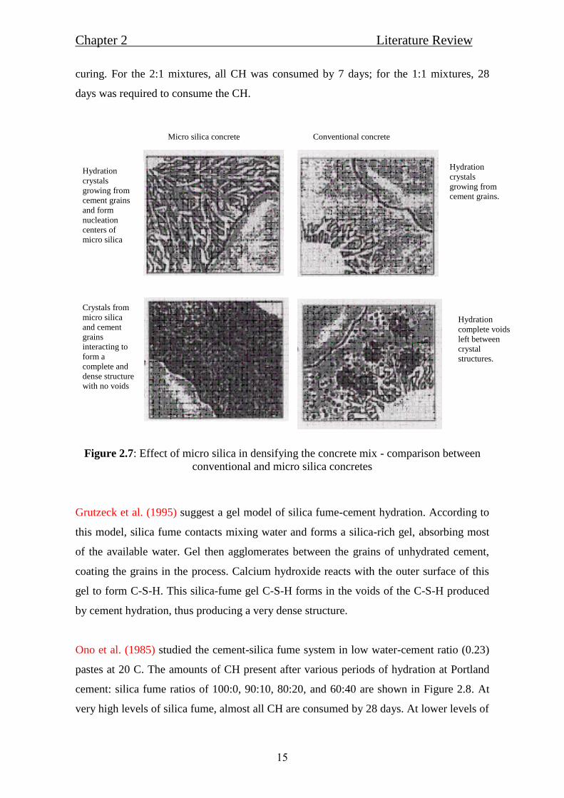
15
curing. For the 2:1 mixtures, all CH was consumed by 7 days; for the 1:1 mixtures, 28
days was required to consume the CH.
Figure 2.7: Effect of micro silica in densifying the concrete mix - comparison between
conventional and micro silica concretes
Grutzeck et al. (1995) suggest a gel model of silica fume-cement hydration. According to
this model, silica fume contacts mixing water and forms a silica-rich gel, absorbing most
of the available water. Gel then agglomerates between the grains of unhydrated cement,
coating the grains in the process. Calcium hydroxide reacts with the outer surface of this
gel to form C-S-H. This silica-fume gel C-S-H forms in the voids of the C-S-H produced
by cement hydration, thus producing a very dense structure.
Ono et al. (1985) studied the cement-silica fume system in low water-cement ratio (0.23)
pastes at 20 C. The amounts of CH present after various periods of hydration at Portland
cement: silica fume ratios of 100:0, 90:10, 80:20, and 60:40 are shown in Figure 2.8. At
very high levels of silica fume, almost all CH are consumed by 28 days. At lower levels of
Hydration
crystals
growing from
cement grains.
Hydration
complete voids
left between
crystal
structures.
Conventional concrete
Hydration
crystals
growing from
cement grains
and form
nucleation
centers of
micro silica
Crystals from
micro silica
and cement
grains
interacting to
form a
complete and
dense structure
with no voids
Micro silica concrete

eviewLiterature R Chapter 2
16
silica fume, e.g., 10 percent, typical of those used in practice, CH is reduced by almost 50
percent at 28 days. These results are supported by those of Huang and Feldman who found
that while silica fume accelerates early hydration and leads to increased production of CH
at times up to 8 hours, at later ages CH is consumed, and for a mixture containing 50
percent silica fume, no CH is detectable after 14 days.
Figure 2.8: Amount of calcium hydroxide (as CaO) in cement pastes containing different
amounts of silica fume
2.5.2.2 The physical effects
Mindess S., (1988) silica fume increases the strength of concrete largely because it
increases the strength of the bond between the cement paste and the aggregate particles.
Wang et al. (1986) found that even small additions (2 to 5 percent) of silica fume
produced a denser structure in the transition zone with a consequent increase in micro
hardness and fracture toughness.
Monteiro and Mehta, (1986) stated that silica fume reduces the thickness of the
transition zone between cement paste and aggregate particles. One reason for this is the
reduction in bleeding. The presence of silica fume accelerates the hydration of cement
during the early stages.

eviewLiterature R Chapter 2
17
Sellevold et al. (1982) found that equal volumes of inert filler (calcium carbonate)
produced the same effect. They concluded that the mere presence of numerous fine
particles whether pozzolanic or not has a catalytic effect on cement hydration.
Wang et al. (1986) also found that the mean size and orientation index of the CH crystals
within the transition zone were reduced by the addition of silica fume. At the interface
itself, the CH crystals will be oriented parallel to the aggregate surface whether silica fume
is present or not, in a study of the texture (preferred orientation) of CH crystals in the
transition zone.
Bache (1981) explained the theory of the packing of solid particles and its effect on the
properties of the material. Because it is a composite, concrete is affected not only by the
packing of particles in the cement paste, but also by their packing near the surfaces of
aggregate particles. Figure 2.9 illustrates how the minute silica fume particles can improve
packing in the boundary zone. Since this is frequently weakest part of a concrete, it is
especially important to improve packing in this region.
Figure 2.9: The boundary zone and the bulk zone between the aggregates
Bache also showed that addition of silica fume could reduce water demand because the
silica-fume particles were occupying space otherwise occupied by water between the
cement grains. This reduction only applies for systems with enough admixtures to reduce
surface forces.

eviewLiterature R Chapter 2
18
It is worth emphasizing here that all of these physical mechanisms depend on thorough
dispersion of the silica-fume particles in order to be effective. This requires the addition of
sufficient quantities of water-reducing admixtures to overcome the effects of surface
forces and ensure good packing of the solid particles. The proper sequence of addition of
materials to the mixer as well as thorough mixing is also essential.
2.5.3 Steel Fibers
Steel fibers are manufactured fibers composed of stainless steel. Composition may include
carbon (C), silicon (Si), manganese (Mn), phosphorus (P), sulfur (S), and other elements.
Hoang et al. (2008) studied the influence of types of steel fiber on properties of ultra-high
performance concrete and self-compacting ultra-high strength concrete has been
manufactured, short steel fiber (straight fiber) with length/diameter = 17/0.2 and long
steel fiber (hooked ends) with length/diameter = 35/0.5 have been added, in order to
improve ductility. By a reasonable combination of two steel fiber types guarantee for high
flowability, flexural strength of over 20 MPa and compressive strength of over 150 MPa.
Kang et al. (2010) studied the tensile fracture properties of Ultra High Performance Fiber
Reinforced Concrete (UHPFRC) considering the effects of the fiber content, they found
that flexural tensile strength of UHPFRC linearly increases with increasing fiber volume
ratio.
Koksal et al. (2008) conducted an experimental study to understand combined effect of
silica fume and steel fiber on the mechanical properties of high strength concretes, Results
show that the use of silica fume increased both the mechanical strength and the modulus
of elasticity of concrete. On the other hand, the addition of steel fibers into concrete
improve toughness of high strength concrete significantly. As the steel fiber volume
fraction increases, the toughness increases, and high values of aspect ratios give higher
toughness. The toughness of high strength steel fiber concrete depends on silica fume
content, the fiber volume fraction and the fiber aspect ratio.

eviewLiterature R Chapter 2
19
2.6 Mixing of fresh UHPFRSCC
Shihada and Arafa, (2010) found that changing the mixing sequences affect the main
properties of UHPC, including density, slump and compressive strength.
Chopin et al., (2004) completed a study to find out the mix-design peculiarities of high-
performance concrete (HPC) and by the way ultra-high performance concrete and self-
consolidating concrete (SCC) that could be responsible for the long mixing time. To
compare the behavior of various mixes, a mathematical model was proposed to fit the
power consumption curve of the mixer and to choose a criterion to determine the
stabilization time of the curve. The parameters studied were the paste content, its
components (silica fume, limestone filler, etc.), the high-range water reducing admixture
(HRWRA) type and dosage and the water/cement (w/c) ratio. The comparison of
stabilization time for 36 different HPC and SCC mixes allowed to highlight the major
influence of w/c ratio, on the stabilization time. The higher the w/c ratio, the lower the
stabilization time. It also appeared that fine content, HRWRA dosage and the use of silica
fume have significant effects on the time necessary to homogenize the material.
2.7 Concluding Remarks
Ultra High Performance Fiber Reinforced Self Compacted Concrete is one of the latest
developments in concrete technology. UHPFRSCC refers to materials with a cement
matrix and a characteristic compressive strength in excess of 120 MPa, possibly attainting
200 MPa.
The hardened concrete matrix of Ultra High Performance Fiber Reinforced Self
Compacted Concrete shows extraordinary strength and durability properties. These
features are the result of using very low amounts of water, high amounts of cement, fibers,
fine aggregates and micro fine powders. These materials are characterized by a dense
microstructure. The sufficient workability is obtained by using superplastisizers.
Silica fume is an essential ingredient of UHPFRSCC. This material comprises extremely
fine particles and not only fills up the space between the cement grains, but also reacts
with the cement, which increasing the bond between cement matrix and amal aggregate
particles.

eviewLiterature R Chapter 2
20
As a result of its superior performance, UHPFRSCC has found application in the storage
of nuclear waste, bridges, roofs, piers, long span girders, shell and seismic-resistant
structures and rehabilitation works of mega structures.

aterial M Chapter 3
21
Chapter (3)
Constituent Materials and Experimental Program
3.1 Introduction
This chapter presents the experimental program and the constituent materials used to
produce UHPFRSCC associated with this research work.
The laboratory investigation consisted of tests for both fresh and hardened concrete
properties. Fresh concrete was tested for slump flow and V-funnel to ensure reasonable
workability and self-compacting ability in the plastic state. The tests for hardened concrete
included compression tests for strength and indirect tensile tests (split cylinder and flexural
strength tests)
The influence of the silica fume dosages, cement/ultra-fine ratio, steel fibers and
polypropylene fibers amounts on the compressive strength concrete together with the
workability and density of UHPFRSCC was studied by preparing several concrete mixes.
The properties of different constituent materials used to produce UHPFRSCC are also
discussed such as moisture content, unit weight, specific gravity and the grain size
distribution. The test procedures, details and equipment used to assess concrete properties
are illustrated in the following sections.
3.2 Characterizations of constituent Materials
UHPFRSCC constituent materials used in this research include ordinary Portland cement,
grey silica fume, steel fibers and polypropylene fibers. Silica fume and cement was used as
micro filler and binder. Quartz sand, in addition to superplastisizers, are used to ensure
suitable workability. Steel and Polypropylene fibers used to improve the strength and
ductility. Proportions of these constituent materials have been chosen carefully in order to
optimize the packing density of the mixture.
aterial M Chapter 3
22
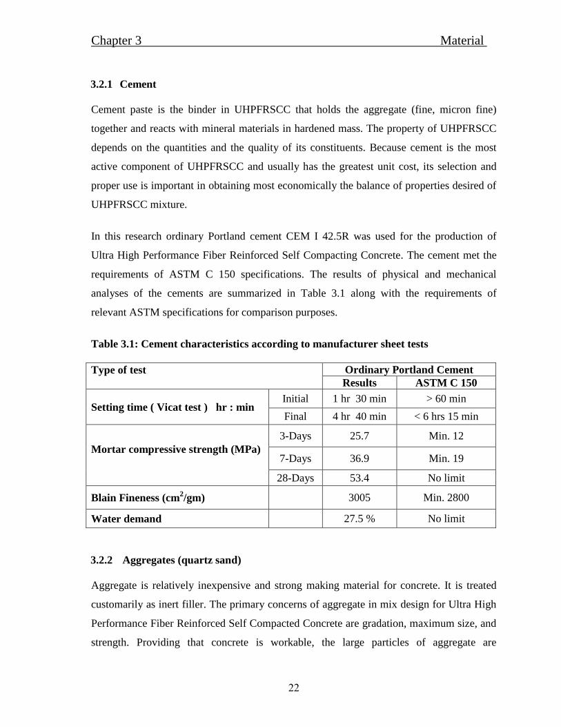
3.2.1 Cement
Cement paste is the binder in UHPFRSCC that holds the aggregate (fine, micron fine)
together and reacts with mineral materials in hardened mass. The property of UHPFRSCC
depends on the quantities and the quality of its constituents. Because cement is the most
active component of UHPFRSCC and usually has the greatest unit cost, its selection and
proper use is important in obtaining most economically the balance of properties desired of
UHPFRSCC mixture.
In this research ordinary Portland cement CEM I 42.5R was used for the production of
Ultra High Performance Fiber Reinforced Self Compacting Concrete. The cement met the
requirements of ASTM C 150 specifications. The results of physical and mechanical
analyses of the cements are summarized in Table 3.1 along with the requirements of
relevant ASTM specifications for comparison purposes.
Table 3.1: Cement characteristics according to manufacturer sheet tests
Type of test
Ordinary Portland Cement
Results ASTM C 150
Setting time ( Vicat test ) hr : min Initial 1 hr 30 min > 60 min
Final 4 hr 40 min < 6 hrs 15 min
Mortar compressive strength (MPa)
3-Days 25.7 Min. 12
7-Days 36.9 Min. 19
28-Days 53.4 No limit
Blain Fineness (cm2/gm) 3005 Min. 2800
Water demand 27.5 % No limit
3.2.2 Aggregates (quartz sand)
Aggregate is relatively inexpensive and strong making material for concrete. It is treated
customarily as inert filler. The primary concerns of aggregate in mix design for Ultra High
Performance Fiber Reinforced Self Compacted Concrete are gradation, maximum size, and
strength. Providing that concrete is workable, the large particles of aggregate are

aterial M Chapter 3
23
undesirable for producing UHPFRSCC. For producing UHPFRSCC, the nominal size
ranges from 0.15 to 0.6 mm for quartz sand (fine aggregate) which are locally available in
Gaza markets. In addition, it is important to ensure that the aggregates are clean, since a
layer of silt or clay will reduce the cement aggregate bond strength, in addition to
increasing the water demand.
Figure 3.1: Aggregate used in mixes: Quartz sand.
3.2.2.1 Specific gravity and Unit weight:
The density of the aggregate is required in mix proportions to establish weight volume
relationships. The density is expressed as the specific gravity, which is dimensionless
relating the density of the aggregate to that of water. The determination of specific gravity
of quartz sand was according to ASTM C128. The specific gravity was calculated at two
different conditions which are the dry condition and the saturated surface dry condition.
Table 3.2 shows the physical properties of quartz sand.
The unit weight or the bulk density of the aggregate is the weight of the aggregate per unit
volume. The unit weight is necessary to select concrete mixtures proportions in
UHPFRSCC .The determination of unit weight was according to ASTM C556. Table 3.2
illustrate the unit weight of quartz sand.

aterial M Chapter 3
24
Table 3.2: Physical property of quartz sand
Unit Weight
(kg/m3) (SSD)
Unit Weight
(kg/m3) (dry)
Specific
Gravity(SSD)
Specific
Gravity(dry)
Aggregate
Size(mm)
1672.588 1662.15 2.675 2.658 0.6
1673.002 1662.64 2.68 2.663 0.5
1673.416 1663.130 2.685 2.668 0.4
1674.100 1663.950 2.697 2.680 0.3
1674.614 1664.000 2.697 2.680 0.15
1673.544 1663.174 2.687 2.670 average
3.2.2.2 Moisture content:
The aggregate moisture is the percentage of the water present in the sample aggregate,
either inside pores or at the surface. Moisture content of the fine aggregate was done
according to ASTM C128, but the final moisture content was zero because fine aggregates
were dried in an oven at temperature (110o C±5). Table 3.3 illustrates the absorption
percentages of quartz sand.
Table 3.3: Water absorption of quartz sand
Water Absorption (%) Aggregate Size(mm)
0.620 0.6
0.625 0.5
0.628 0.4
0.636 0.3
0.639 0.15
0.629 average
From the previous results, it can be observed that the specific gravity ranges from 2.658 to
2.697 for quartz sand, and the water absorption tends to increase with the size reduction.
3.2.3 Water
Drinkable water was used in all concrete mixtures and in the curing of specimens.

aterial M Chapter 3
25
3.2.4 Admixture
The chemical admixture used is superplasticizer manufactured to confirm to ASTM-C-494
specifications (Type G and F) see Table 3.4 and Figure 3.2. When superplasticizer is added
to concrete mix, it shows a strong self-leveling behavior therefore suitable for the
production of self-compacting concrete and improves the properties of fresh and hardened
concrete. This plasticizing effect can be used to increase the workability of fresh concrete
without causing segregation, water reduction (resulting in high density, durability and
strength), high flowability, improve shrinkage and creep behavior and finally improve
water impermeability.
Table 3.4: Technical data for the "Sika ViscoCrete – 5930"
Type Property
Appearance Turbid liquid
Density (kg/l) 1.08 ± 0.005
Basis Aqueous solution of modified polycarboxylate
Toxicity Non-Toxic under relevant health and safety codes
Figure 3.2: The chemical admixture (Superplastisizer).

aterial M Chapter 3
26
3.2.5 Silica Fume
Silica fume is a byproduct resulting from the reduction of high-purity quartz with coal or
coke and wood chips in an electric arc furnace during the production of silicon metal or
ferrosilicon alloys. The silica fume which condenses from the gases escaping from the
furnaces has a very high content of amorphous silicon dioxide and consists of very fine
spherical particles. (ACI 548.6R - 96).
The silica fume "Sika -Fume" was supplied from SIKA Company. Table 3.5 shows the
technical data supplied from the SIKA Company.
Table 3.5: The technical data for the "Sika – Fume”
Type Property
Appearance Grey powder
Specific gravity 2.20
Chloride Content Nil
Toxicity Non-Toxic
3.2.6 Steel fibers
Straight stainless steel fibers with length/diameter ≈ 60, Tensile strength ≈ 650 MPa, and
density of 7.8 g/cm3, have been added, to improve hardened concrete properties especially
the ductility.
Figure 3.3: Steel fibers

aterial M Chapter 3
27
3.2.7 Polypropylene fibers
Polypropylene fibers are thermoplastic polymers, meet the requirements of ASTM C-1116,
with a specific gravity of 0.9 g/cm3 and length of 1.5 cm, added to improve the
UHPFRSCC shrinkage and ductility properties.
Figure 3.4: Polypropylene fibers
3.3 Mix Design of UHPFRSCC
Mix design process is summarized in Figure 3.5.
1. What is Required !! based on related specifications
2. Select needed materials
3. Design mix proportions
4. Laboratory testing
5. Adjust proportions or verify.
Figure 3.5: Mix design process

aterial M Chapter 3
28
3.4 Preparation of UHPFRSCC
After selection of all needed constituent materials and amounts to be used (mix designs); all
materials are weighed properly. Then mixing with a power-driven tilting revolving drum
mixer started to ensure that all particles are surrounded with cement paste and silica fume
and all the materials and fibers (i.e. steel and polypropylene fibers) should be distributed
homogeneously in the concrete mass.
Mixing procedure was according following steps: (Arafa et al., 2010):
1) Adding 40 % of superplasticizer to the mixing water.
2) Placing all dry materials (cement, silica fume, quartz sand, steel fibers and
polypropylene fibers) in the mixer pan, and mixing for 2 minutes.
3) Adding water (with 40% of superplasticizer) to the dry materials, slowly for 2 minutes.
4) Waiting 1 minute then adding the remaining superplasticizer to the mixture for 30
seconds.
5) Continuation of mixing as the UHPFRSCC changes from a dry powder to a thick paste.
After final mixing, the mixer is stopped, turned up with its end right down, and the fresh
homogeneous concrete is poured into a clean plastic pan.
The casting of all UHPFRSCC specimens used in this research completed within 20
minutes after being mixed. All specimens were cast and covered to prevent evaporation.
3.5 Test Program
As stated in the first chapter of this research, the aim of this research is to produce Ultra
High Performance Fiber Reinforced Self Compacted Concrete (UHPFRSCC) in Gaza Strip
by using local available materials. The test program adopted to achieve this objectives is
summarized in Figure 3.6.

aterial M Chapter 3
29
Figure 3.6: Test Program
3.6 Equipment and testing procedure
The laboratory testing consists of tests for both fresh and hardened concrete. Fresh concrete
tested for slump and V-funnel. Hardened concrete tested for compressive strength, indirect
tensile tests (split cylinder test and flexural test).
3.6.1 Tests Applied On Fresh Concrete
Based on previous experiences, as for site quality control, two test methods are generally
sufficient to monitor production quality, and typical combinations are slump flow and V-
funnel (EFNARC, 2005), this combination is adopted in this research.
Best mix
Steel fibers
Silica fume
Test the effect of
Polypropylene

aterial M Chapter 3
30
3.6.1.1 Slump flow, T500 tests
The slump-flow and T500 time is a test to measure the flowability and the flow rate of self-
compacting concretes in the absence of obstructions. It is based on the slump test to
measure two parameters, the flow speed and the flow time. The result is an indication of the
filling ability of self-compacting concrete. The T500 time is also a measure of the speed of
flow and hence the viscosity of the self-compacting concrete, also the test is not suitable
when the maximum size of the aggregate exceeds 40 mm.
The fresh concrete is placed into a cone as for the normal slump test as shown in Figure
3.7. When the cone is left upwards, the time from commencing upward movement of the
cone to when the concrete has flowed to a diameter of 500 mm is measured; this is the
T500 time. The largest diameter of the flow spread of the concrete and the perpendicular
diameter are then measured and the mean is the slump-flow, Figure 3.8.
Don‟t forget to check the concrete spread for segregation. The cement paste/mortar may
segregate from the aggregate and steel fibers to give a ring of paste/mortar extending
several millimeters beyond them.
Figure 3.7: Slump cone and base plate
Figure 3.8: Self-compacted concrete at the lab.

aterial M Chapter 3
31
Table 3.6: Self-compacting criteria (Slump flow, T500 test)
Test Unit Min. Max.
Slump flow mm 550 850
T500 mm Slump flow Sec. 2 9
3.6.1.2 V-funnel test
The V-funnel test is used to assess the viscosity and filling ability of self-compacting
concrete with a maximum size aggregate of 20mm. The V shaped funnel as shown in
Figure 3.9 is filled with fresh concrete and the time taken for the concrete to flow out of the
funnel is measured and recorded as the V-funnel flow time.
Figure 3.9: V-Funnel
Table 3.7: Self-compacting criteria (V-funnel)
Test Unit Min. Max.
V-funnel Sec. 6 12

aterial M Chapter 3
32
3.6.2 Tests Applied On Hardened Concrete
3.6.2.1 Compression Test
A significant portion of this research focused on the behaviors of UHPFRSCC cube
specimens under compressive loading. The compressive tests discussed in this section were
all completed nominally according to (ASTM C109. 2004) standard test method for cubes.
Total number of 126 cubes were manufactured. For each batch of UHPFRSCC made,
100x100x100 mm cube specimens were prepared, as shown in Figure 3.10. The cubes were
filled with fresh concrete without compacting, after preparing the specimens, cubes were
covered with plastic sheets for about 24 hours to prevent moisture loss.
Figure 3.10: Cube specimens Figure 3.11: Cubes at curing basin
After 24 hours; Cubes extracted from forms and stored in water (curing phase) up to the
time of test. Before testing, specimens were air dried for 10 to15 minutes and any loose
sand grains or incrustations from the faces that will be in contact with the bearing plate of
the testing machine are removed. The cubes then placed in the testing machine so that the
load is applied through flat and parallel sides.
The compressive strength of the specimen, σcomp (in MPa), is calculated by dividing the
maximum load carried by the cube specimen during the test by the cross sectional area of
the specimen.
The compressive strength was determined at different ages 7, 14, and 28 days. At least
three of these cubes were tested for each period the mean value of the specimens was
considered as the compressive strength of the experiment.
aterial M Chapter 3
33
3.6.2.2 Splitting Cylinder Test
Total number of 42 cylinders were manufactured. The splitting tensile strength of
UHPFRSCC was measured based on (ASTM C496. 2004) Standard test Method for
Splitting Tensile Strength of Cylindrical Concrete Specimens.
This test often referred to as the split cylinder test, indirectly measures the tensile strength
of concrete by compressing a cylinder through a line load applied along its length. The
failure of concrete in tension is governed by micro-cracking, associated particularly with
the interfacial region between the aggregate particles and the cement, also called interfacial
transition zone (ITZ). The load applied (compressive force) on the cylindrical concrete
specimen induces tensile and shear stresses on the aggregate particles inside the specimen,
generating the bond failure between the aggregate particles and the cement paste. Usually,
splitting tensile strength test is used to evaluate the shear resistance provided by concrete
elements. However, the most important advantage is that, when applying the splitting
procedure, the tensile strengths are practically independent of either the test specimen or of
the test machine sizes, being only a function of the concrete quality alone. Thus, much
inconvenience is eliminated, particularly with respect to the scale coefficient, which is
involved in direct tensile tests. For this reason, this procedure is considered to reproduce
more exactly the real concrete tensile strength.
The tensile strength of concrete is evaluated using a split cylinder test, in which a
cylindrical specimen is placed on its side and loaded in diametrical compression, so to
induce transverse tension. Practically, the load applied on the cylindrical concrete specimen
induces tensile stresses on the plane containing the load and relatively high compressive
stresses in the area immediately around it. When the cylinder is compressed by the two
plane-parallel face plates, situated at two diametrically opposite points on the cylinder
surface then, along the diameter passing through the two points, as shown in Figure 3.15,
the major tensile stresses are developed which, at their limit, reach the fracture strength
value ASTM C496 indicates that the maximum fracture strength can be calculated based on
the following equation.

aterial M Chapter 3
34
DL
2P Fsp
Where: P is the fracture compression force acting along the cylinder;
D is the cylinder diameter;
π = 3.14;
L is the cylinder length.
The load and stress distribution pattern across the cross section if it is assumed that the load
is concentrated at the tangent points then, over the cross section, only tensile stresses would
be developed. In practice, however, the load is distributed over a finite width owing to
material deformations. So, over the cross section, horizontal compressive stresses are
developed too, in the close vicinity of the contact point between the press platens and the
material. Since the compressive stresses only develop to a small depth in the cross section,
it may be assumed that the tensile stresses are distributed evenly along the diameter where
the splitting takes place, see Figure 3.12.
Figure 3.12: Split cylinder test
Figure 3.13: Cylinders damages after test
aterial M Chapter 3
35
All cylinder specimens were tested after 28 days from casting. Three cylinders were tested
for each patch, the mean values of the specimens were considered as split cylinder strength.
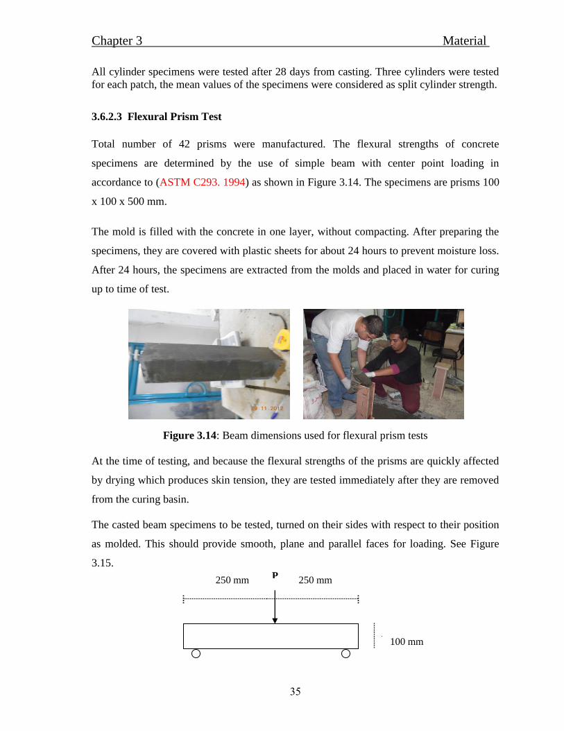
3.6.2.3 Flexural Prism Test
Total number of 42 prisms were manufactured. The flexural strengths of concrete
specimens are determined by the use of simple beam with center point loading in
accordance to (ASTM C293. 1994) as shown in Figure 3.14. The specimens are prisms 100
x 100 x 500 mm.
The mold is filled with the concrete in one layer, without compacting. After preparing the
specimens, they are covered with plastic sheets for about 24 hours to prevent moisture loss.
After 24 hours, the specimens are extracted from the molds and placed in water for curing
up to time of test.
Figure 3.14: Beam dimensions used for flexural prism tests
At the time of testing, and because the flexural strengths of the prisms are quickly affected
by drying which produces skin tension, they are tested immediately after they are removed
from the curing basin.
The casted beam specimens to be tested, turned on their sides with respect to their position
as molded. This should provide smooth, plane and parallel faces for loading. See Figure
3.15.
100 mm
250 mm P 250 mm

aterial M Chapter 3
36
Figure 3.15: Schematic view for flexure test of concrete by center-point loading
The pedestal on the base plate of the machine is centered directly below the center of the
upper spherical head, and the bearing plate and support edge assembly are placed on the
pedestal. The center loading device is attached to the spherical head. The test specimen is
turned on its side with respect to its position as molded and it is placed on the supports of
the testing device. This provides smooth, plane, and parallel faces for loading. The
longitudinal center line of the specimen is set directly above the midpoint of both supports.
The center point loading device is adjusted so that its bearing edge is at exactly right angles
to the length of the beam and parallel to its top face as placed, with the center of the bearing
edge directly above the center line of the beam and at the center of the span length. The
load contacts with the surface of the specimen at the center. If full contact is not obtained
between the specimen and the load applying or the support blocks so that there is a gap, the
contact surfaces of the specimen are capped.
The specimen is loaded continuously and without shock at until rupture occurs. Finally, the
maximum load indicated by the testing machine is recorded.
The flexural strength of the beam, Fr (in MPa), can be calculated by using the following
equation:
Where: P = maximum applied load indicated by the testing machine;
L = span length;
B = average width of specimen, at the point of fracture;
D = average depth of specimen, at the point of fracture)
All beam specimens were tested after 28 days from casting. Three beams were tested for
each patch, the mean values of the specimens were considered as flexural strength of the
beam.
22BD
3PLFr

aterial M Chapter 3
37
3.6.2.4 Unit weight
In this research, the unit weight of the concrete cube specimen is the theoretical density.
The density is calculated by dividing the weight of each cube by the volume. The same
cube specimens which are used to determine the compressive strength was used to
determine the density and the tests were carried out according to ASTM C642. (2004).
3.6.3 Curing Procedure
Curing is an important process to prevent the concrete specimens from losing of moisture
while it is gaining its required strength. Lack of curing will tend to lead the concrete
specimens to perform less well in its strength required.
All concrete samples were placed in curing basin after 24 hours from casing. All samples
remained in the curing basin up to time of testing at the specified age. The curing condition
of lab basin followed the ASTM C192, (2004). Curing water temperature is around 25oC.
Discussionand sesultRTest 4Chapter
38
Chapter (4)
Test Results and Discussion
4.1 Introduction
Series of tests were carried out on the concrete specimens to develop, study and evaluate
the mechanical properties of fresh and hardened Ultra High Performance Fiber Reinforced
Self Compacted Concrete. This chapter discusses the results obtained from 14 different
tests adopted in the testing program. Results include slump flow test, V-funnel, unit weight,
compressive strength and indirect tensile strength tests.
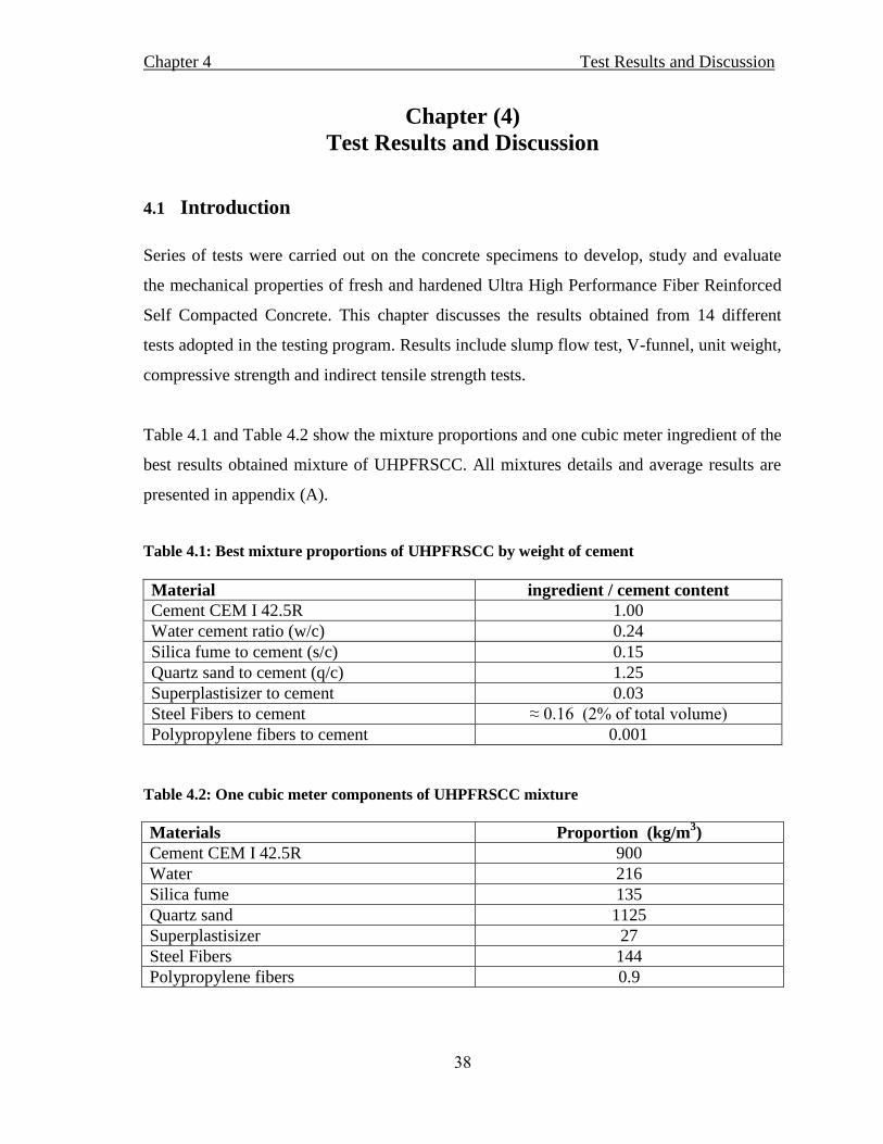
Table 4.1 and Table 4.2 show the mixture proportions and one cubic meter ingredient of the
best results obtained mixture of UHPFRSCC. All mixtures details and average results are
presented in appendix (A).
Table 4.1: Best mixture proportions of UHPFRSCC by weight of cement
ingredient / cement content Material
1.00 Cement CEM I 42.5R
0.24 Water cement ratio (w/c)
0.15 Silica fume to cement (s/c)
1.25 Quartz sand to cement (q/c)
0.03 Superplastisizer to cement
≈ 0.16 (2% of total volume) Steel Fibers to cement
0.001
Polypropylene fibers to cement
Table 4.2: One cubic meter components of UHPFRSCC mixture
Materials Proportion (kg/m3)
Cement CEM I 42.5R 900
Water 216
Silica fume 135
Quartz sand 1125
Superplastisizer 27
Steel Fibers 144
Polypropylene fibers 0.9
Discussionand sesultRTest 4Chapter
39
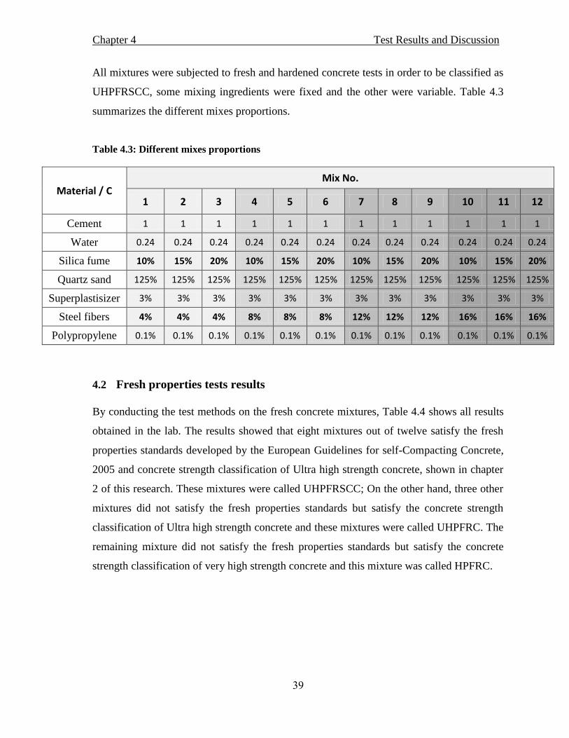
All mixtures were subjected to fresh and hardened concrete tests in order to be classified as
UHPFRSCC, some mixing ingredients were fixed and the other were variable. Table 4.3
summarizes the different mixes proportions.
Table 4.3: Different mixes proportions
Material / C Mix No.
1 2 3 4 5 6 7 8 9 10 11 12
Cement 1 1 1 1 1 1 1 1 1 1 1 1
Water 0.24 0.24 0.24 0.24 0.24 0.24 0.24 0.24 0.24 0.24 0.24 0.24
Silica fume 10% 15% 20% 10% 15% 20% 10% 15% 20% 10% 15% 20%
Quartz sand 125% 125% 125% 125% 125% 125% 125% 125% 125% 125% 125% 125%
Superplastisizer 3% 3% 3% 3% 3% 3% 3% 3% 3% 3% 3% 3%
Steel fibers 4% 4% 4% 8% 8% 8% 12% 12% 12% 16% 16% 16%
Polypropylene 0.1% 0.1% 0.1% 0.1% 0.1% 0.1% 0.1% 0.1% 0.1% 0.1% 0.1% 0.1%
4.2 Fresh properties tests results
By conducting the test methods on the fresh concrete mixtures, Table 4.4 shows all results
obtained in the lab. The results showed that eight mixtures out of twelve satisfy the fresh
properties standards developed by the European Guidelines for self-Compacting Concrete,
2005 and concrete strength classification of Ultra high strength concrete, shown in chapter
2 of this research. These mixtures were called UHPFRSCC; On the other hand, three other
mixtures did not satisfy the fresh properties standards but satisfy the concrete strength
classification of Ultra high strength concrete and these mixtures were called UHPFRC. The
remaining mixture did not satisfy the fresh properties standards but satisfy the concrete
strength classification of very high strength concrete and this mixture was called HPFRC.
Discussionand sesultRTest 4Chapter
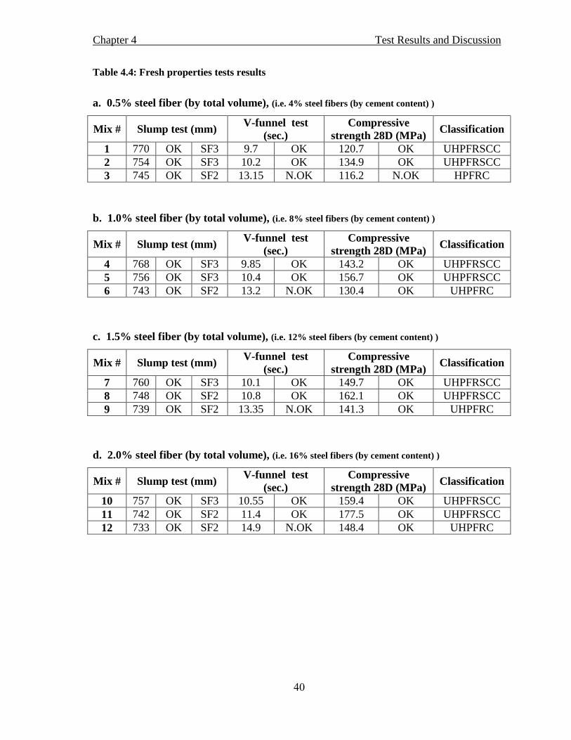
40
Table 4.4: Fresh properties tests results
a. 0.5% steel fiber (by total volume), (i.e. 4% steel fibers (by cement content) )
Mix # Slump test (mm) V-funnel test
(sec.)
Compressive
strength 28D (MPa) Classification
1 770 OK SF3 9.7 OK 120.7 OK UHPFRSCC
2 754 OK SF3 10.2 OK 134.9 OK UHPFRSCC
3 745 OK SF2 13.15 N.OK 116.2 N.OK HPFRC
b. 1.0% steel fiber (by total volume), (i.e. 8% steel fibers (by cement content) )
Mix # Slump test (mm) V-funnel test
(sec.)
Compressive
strength 28D (MPa) Classification
4 768 OK SF3 9.85 OK 143.2 OK UHPFRSCC
5 756 OK SF3 10.4 OK 156.7 OK UHPFRSCC
6 743 OK SF2 13.2 N.OK 130.4 OK UHPFRC
c. 1.5% steel fiber (by total volume), (i.e. 12% steel fibers (by cement content) )
Mix # Slump test (mm) V-funnel test
(sec.)
Compressive
strength 28D (MPa) Classification
7 760 OK SF3 10.1 OK 149.7 OK UHPFRSCC
8 748 OK SF2 10.8 OK 162.1 OK UHPFRSCC
9 739 OK SF2 13.35 N.OK 141.3 OK UHPFRC
d. 2.0% steel fiber (by total volume), (i.e. 16% steel fibers (by cement content) )
Mix # Slump test (mm) V-funnel test
(sec.)
Compressive
strength 28D (MPa) Classification
10 757 OK SF3 10.55 OK 159.4 OK UHPFRSCC
11 742 OK SF2 11.4 OK 177.5 OK UHPFRSCC
12 733 OK SF2 14.9 N.OK 148.4 OK UHPFRC

Discussionand sesultRTest 4Chapter
41
4.2.1 Effect of silica fume and steel fibers on slump test results
Three different doses of silica fume added, (10%, 15% and 20%) by mass of the Portland
cement and four different percentages of steel fibers (by the total volume) (0.5%, 1.0%,
1.5% and 2%) have been used to study the influence on fresh UHPFRSCC properties. The
water/cement ratio 0.24 was kept constant for all mixtures and superplastisizer/cement also
kept to 0.03.
Figure 4.1, shows that the larger is the silica fume amount, the smaller is the slump flow
results, this can be justified because silica fume is a very fine materials need much more
amount of water to break the flocculation forces. And as the steel fibers increases, the
slump flow results decreases. Results agree with that of previous research of Abu Shaban,
(2012).
Figure 4.1: Effect of silica fume and steel fibers on slump test results
4.2.2 Effect of silica fume and steel fibers on V-Funnel test results
Table 4.4 Shows the V-Funnel test time results for the mixes, these results also reflect the
concrete viscosity ratio which is inversely proportional with the V-Funnel time, in other
words when the V-Funnel time increases the concrete loses its viscosity.

Discussionand sesultRTest 4Chapter
42
Figure 4.2 shows the effect of adding 10%, 15% and 20% silica fume, by the mass of
Portland cement and four different percentages of steel fibers (by the total volume) (0.5%,
1.0%, 1.5% and 2%) on the UHPFRSCC V-Funnel time.
It was shown that the larger is the amount of the silica fume and steel fibers, the lower is
the viscosity of mixtures. And, when the silica fume percentage equal or above 20%,
mixtures cannot be considered as a self-compacting concrete any more. High percentage of
silica fume as a fine Pozzolanic material fill all the spaces between cement particles and
need much more high range water reducer superplasticizer, that would led to a very rigid
and not self-compacted concrete.
Figure 4.2: Effect of silica fume and steel fibers on V-funnel time results
The obtained results agree with that of previous research of Abu Shaban, (2012).
4.2.3 Segregation in the trial mixes
In all trial mixtures, where the W/C was constant and equal to 0.24, no segregation was
observed and all mixtures were homogenous and fibers were well distributed through every
batch.

Discussionand sesultRTest 4Chapter
43
4.3 Hardened properties tests results
Laboratory tests were conducted to evaluate and study the hardened properties of
UHPFRSCC. Results are the unit weight, compressive strength test and indirect tensile
tests. Mean results are summarized in Table 4.5.
Table 4.5: Hardened properties tests results
a. 0.5% steel fiber (by total volume), (i.e. 4% steel fibers (by cement content) )
Mix # Unit weight
Kg/m3
Compressive strength MPa Splitting tensile
strength 28days
MPa 7 days 14 days 28 days
1 2554 85.3 104.9 120.7 12.5
2 2542 95.5 117.4 134.9 14.2
3 2539 82.2 101.1 116.2 12.1
b. 1.0% steel fiber (by total volume), (i.e. 8% steel fibers (by cement content) )
Mix # Unit weight
Kg/m3
Compressive strength MPa Splitting tensile
strength 28days
MPa 7 days 14 days 28 days
4 2587 101.3 124.6 143.2 15.1
5 2577 111.1 136.3 156.7 16.4
6 2565 92.2 113.4 130.4 13.7
c. 1.5% steel fiber (by total volume), (i.e. 12% steel fibers (by cement content) )
Mix # Unit weight
Kg/m3
Compressive strength MPa Splitting tensile
strength 28days
MPa 7 days 14 days 28 days
7 2590 106.1 130.2 149.7 15.7
8 2581 114.6 141 162.1 17.1
9 2574 100.2 122.9 141.3 14.8
d. 2.0% steel fiber (by total volume), (i.e. 16% steel fibers (by cement content) )
Mix # Unit weight
Kg/m3
Compressive strength MPa Splitting tensile
strength 28days
MPa 7 days 14 days 28 days
10 2601 112.9 140.3 159.4 16.1
11 2592 125.7 156.2 177.5 18.7
12 2583 105.1 130.6 148.4 15.6

Discussionand sesultRTest 4Chapter
44
4.3.1 Effects of silica fume and steel fibers on UHPFRSCC unit weight
Figure 4.3: Effect of silica fume and steel fibers on UHPFRSCC unit weight
Figure 4.3 summarizes the effect of silica fume and steel fibers on the UHPFRSCC unit
weight, the results show that the density of concrete decreases when increasing the silica
fume content, but increases when the amount of steel fibers increases.
4.3.2 Effects of silica fume and steel fibers on UHPFRSCC compressive strength
Figure 4.4: Effect of silica fume and steel fibers on UHPFRSCC compressive strength (7days)

Discussionand sesultRTest 4Chapter
45
Figure 4.5: Effect of silica fume and steel fibers on UHPFRSCC compressive strength
(14days)
Figure 4.6: Effect of silica fume and steel fibers on UHPFRSCC compressive strength
(28days)

Discussionand sesultRTest 4Chapter
46
Results shown in Table 4.5, Figure 4.4, Figure 4.5 and Figure 4.6 demonstrate that it is
possible to develop UHPFRSCC with different silica fume and steel fibers amounts.
It can be observed that increasing the silica fume content from 10% to 15% effectively
increases the compressive strength of concrete. But increasing the silica fume content from
15% to 20% decreases the compressive strength. Results agree with that of Abu Shaban,
(2012).
This can be explained according to what have been mentioned in EFNARC, that the silica
fume works in two levels, the Pozzolanic reaction and the physical function. The hydration
of Portland cement produces many compounds; including calcium silicate hydrates (C-S-H)
and calcium hydroxide (CH). When silica fume is added to fresh concrete, it chemically
reacts with the CH to produce additional C-S-H which improve the bond between the
cement and the surface of the aggregate, more ever the silica fume particle can fill the voids
creates by free water in the matrix. This function is called particle packing refines the
microstructure of the concrete, thus creating a much denser pore structure the benefit of this
reacts is twofold; increasing compressive strength and decreasing total pores volume
(EFNARC, 2005). But when silica fume percent increased significantly, the strength
decreases, this can be explained that the silica fume can react to a certain level, after that
the silica fume did not participate in the hydration reaction and remain inert in concrete as
the weakest point.
On the other hand, when the steel fibers amount increases, the compressive strength
increases also.
The maximum compressive strength of the concrete specimens was achieved by using 15 %
silica fume by the mass of cement, and addition of 2% of steel fibers of the total volume.
where a compressive strength up to 177.5 MPa, which met the target compressive strength
for the UHPFRSCC and agree with results obtained by Hoang K. et al., (2008).

Discussionand sesultRTest 4Chapter
47
4.3.3 Compressive strength – Time relationship
Figures 4.4 through 4.6 show the compressive strength results at several ages of the
concrete mixtures.
For the mixture #11 with the best results, Figure 4.7 shows the variation of mean
compressive strength with age.
Figure. 4.7: Mean compressive strength Vs. age of mix #11
Results of Figure 4.7 show that this mixture can achieve a mean compressive strength of
concrete specimens near 177.5 MPa at an age of 28 days. Where the curing was done at
room temperature by immersion in water without any heat treatment.
Figure 4.8 shows the mean compressive strength Vs. age of the mix.

Discussionand sesultRTest 4Chapter
48
Figure 4.8: Mean compressive strength Vs. age.
ACI Committee 209, 2033 recommends the following expressions to predict the
compressive strength (fc‟) of Normal Strength Concrete (NSC) with strengths up 41 MPa at
any time:
Where a = 4 (cement type I), β = 0.15 (moist curing), fc28 = 28 days strength and t is the age
of concrete.
Ratios for compressive strengths at different ages of UHPFRSCC concrete fct (7, 14, and 28
days), and that of ACI Committee 209, 2033 expressions are summarized in Table 4.6
shown below.
Table 4.6: Mean ratio of ( fct / fc28) for UHPFRSCC
Age of Cubes (days) Mean ratio of ( fct / fc28)
“Results”
Mean ratio of ( fct / fc28)
“ACI 209, 2033”
7 0.71 0.7
14 0.87 0.88
28 1 1
(MPa) )( t
)( 28ctc fta
f

Discussionand sesultRTest 4Chapter
49
Table 4.6 and Figure 4.9, show results very close to that of ACI Committee 209, 2033
expressions, and that expression can be used for concrete with strength up to 177 MPa.
Figure 4.9: Comparison of (fct / fc28 ) between NSC and UHPFRSCC at different ages .
4.3.4 Effects of silica fume and steel fibers on UHPFRSCC splitting strength
Figure 4.10 shows the effect of adding silica fume 10%, 15% and 20% by mass of cement,
and the addition of steel fibers with 0.5%, 1.0%, 1.5% and 2% by total volume on the
UHPFRSCC splitting tensile strength.

Discussionand sesultRTest 4Chapter
50
Figure. 4.10: Effect of silica fume and steel fibers on UHPFRSCC splitting tensile strength @
age of 28 Days.
From figure 4.10, it can be stated that the larger is the steel fiber amount, the larger is the
splitting tensile strength, and when silica fume increased from 10% to 15% the strength
increased, but when the amount is above 15%, the splitting tensile strength decreased.
The obtained results can be justified as, the addition of steel fibers with the tensile strength
of 650 MPa, distributed homogenously within every batch will sustain the developed
tensile stresses, thus increase the splitting tensile strength of specimens.
Finally, the above results show that mixtures can achieve a mean splitting tensile strength
of concrete specimens of 18.7 MPa at an age of 28 days. Curing was at 25oC by immersion
in water without heat treatment. The standard deviation value was very low ≈ 0.3 MPa.

Discussionand sesultRTest 4Chapter
51
4.3.5 Effects of silica fume and steel fibers on UHPFRSCC flexural strength
Figure 4.11: Effect of silica fume and steel fibers on UHPFRSCC Flexural strength @ age
of 28 Days.
From figure 4.11, it can be concluded that the larger is the steel fiber amount, the larger is
the flexural strength, and when silica fume increased from 10% to 15% the strength
increased, but when the amount is above 15%, the flexural strength decreased. Results
agree with that obtained by Hoang K. et al., (2008).
Obtained results can be justified as a better bonding developed due to the use of silica
fume, which is the most effective way to get the Interface Transition Zone (ITZ) denser, it
eliminates many of the large pores in this zone and increases the strength of the bond
between the cement paste and the fibers, thus reducing the pores in cement paste. And the
addition of steel fibers with the ultimate tensile strength of 650 MPa, distributed
homogenously within every batch and work as a reinforcement, will sustain the developed
tensile stresses, thus increase the flexural strength of specimens.
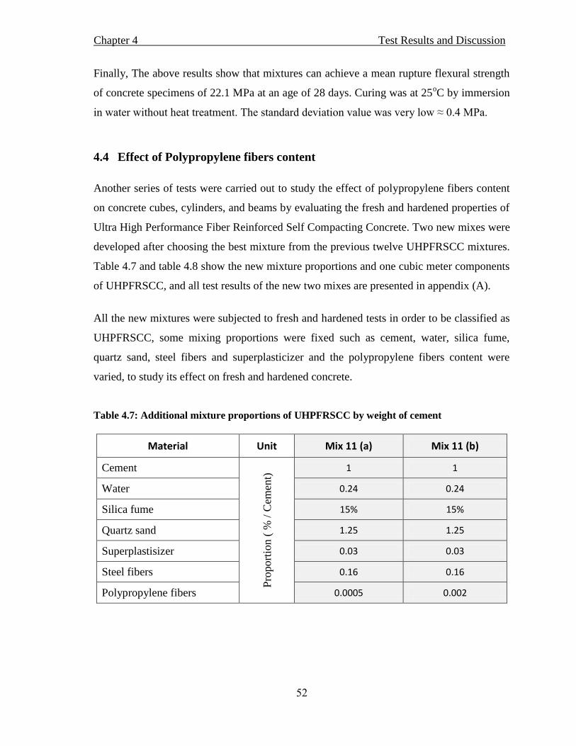
Discussionand sesultRTest 4Chapter
52
Finally, The above results show that mixtures can achieve a mean rupture flexural strength
of concrete specimens of 22.1 MPa at an age of 28 days. Curing was at 25oC by immersion
in water without heat treatment. The standard deviation value was very low ≈ 0.4 MPa.
4.4 Effect of Polypropylene fibers content
Another series of tests were carried out to study the effect of polypropylene fibers content
on concrete cubes, cylinders, and beams by evaluating the fresh and hardened properties of
Ultra High Performance Fiber Reinforced Self Compacting Concrete. Two new mixes were
developed after choosing the best mixture from the previous twelve UHPFRSCC mixtures.
Table 4.7 and table 4.8 show the new mixture proportions and one cubic meter components
of UHPFRSCC, and all test results of the new two mixes are presented in appendix (A).
All the new mixtures were subjected to fresh and hardened tests in order to be classified as
UHPFRSCC, some mixing proportions were fixed such as cement, water, silica fume,
quartz sand, steel fibers and superplasticizer and the polypropylene fibers content were
varied, to study its effect on fresh and hardened concrete.
Table 4.7: Additional mixture proportions of UHPFRSCC by weight of cement
Material Unit Mix 11 (a) Mix 11 (b)
Cement
Pro
port
ion (
% /
Cem
ent)
1 1
Water 0.24 0.24
Silica fume 15% 15%
Quartz sand 1.25 1.25
Superplastisizer 0.03 0.03
Steel fibers 0.16 0.16
Polypropylene fibers 0.0005 0.002
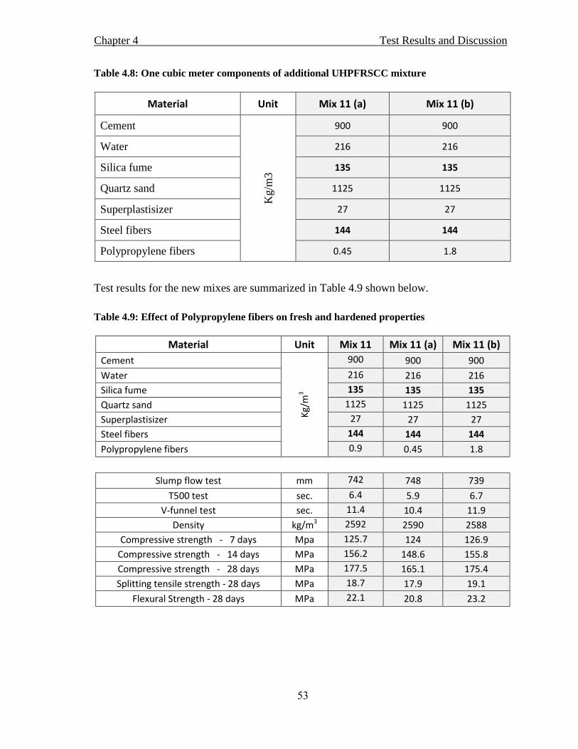
Discussionand sesultRTest 4Chapter
53
Table 4.8: One cubic meter components of additional UHPFRSCC mixture
Material Unit Mix 11 (a) Mix 11 (b)
Cement
Kg/m
3
900 900
Water 216 216
Silica fume 135 135
Quartz sand 1125 1125
Superplastisizer 27 27
Steel fibers 144 144
Polypropylene fibers 0.45 1.8
Test results for the new mixes are summarized in Table 4.9 shown below.
Table 4.9: Effect of Polypropylene fibers on fresh and hardened properties
Material Unit Mix 11 Mix 11 (a) Mix 11 (b)
Cement
Kg/
m3
900 900 900
Water 216 216 216
Silica fume 135 135 135
Quartz sand 1125 1125 1125
Superplastisizer 27 27 27
Steel fibers 144 144 144
Polypropylene fibers 0.9 0.45 1.8
Slump flow test mm 742 748 739
T500 test sec. 6.4 5.9 6.7
V-funnel test sec. 11.4 10.4 11.9
Density kg/m3 2592 2590 2588
Compressive strength - 7 days Mpa 125.7 124 126.9
Compressive strength - 14 days MPa 156.2 148.6 155.8
Compressive strength - 28 days MPa 177.5 165.1 175.4
Splitting tensile strength - 28 days MPa 18.7 17.9 19.1
Flexural Strength - 28 days MPa 22.1 20.8 23.2

Discussionand sesultRTest 4Chapter
54
Figure 4.12: Effect of Polypropylene fibers on slump test
Figure 4.12 shows the effect of adding 0.45, 0.90 and 1.80 kg/m3
polypropylene fibers by
the total volume of batch. It shows that the mixtures lose some of its flowability when the
polypropylene fibers percentage increases, but still classified as self-compacting concrete.
Figure 4.13: Effect of Polypropylene fibers on V-funnel test
Figure 4.13 shows the effect of adding 0.45, 0.90 and 1.80 Kg/m3
polypropylene fibers by
the total volume of batch on the V-Funnel test. It also shows that the mixtures lose some of
its viscosity when the polypropylene fibers percentage increases, but still classified as self-
compacting concrete

Discussionand sesultRTest 4Chapter
55
Figure 4.14: Effect of Polypropylene fibers on Unit weight
Figure 4.14 shows the effect of adding 0.45, 0.90 and 1.80 Kg/m3
polypropylene fibers by
the total volume of batch on the unit weight of hardened concrete. It can be observed that
the difference is very small, it could be because of the small amount of Polypropylene
fibers when compared with other contents.
Figure 4.15: Effect of Polypropylene fibers on compressive strength
Figure 4.15 shows the effect of adding 0.45, 0.90 and 1.80 kg/m3
polypropylene fibers by
the total volume of batch on the compressive strength at different ages. It can be observed
that the optimum amount is 0.9 kg/m3 for all ages.

Discussionand sesultRTest 4Chapter
56
Figure 4.16: Effect of Polypropylene fibers on splitting tensile strength at the age of 28 days.
Figure 4.16 shows the effect of adding 0.45, 0.90 and 1.80 kg/m3
polypropylene fibers by
the total volume of batch on the splitting tensile strength at the age of 28 days. It can be
observed that the optimum amount is 1.8 kg/m3. This is because the added polypropylene
fibers, works as a secondary reinforcement sustain some of the tensile loads developed by
the test.
Figure 4.17: Effect of Polypropylene fibers on flexural strength at the age of 28 days.
Discussionand sesultRTest 4Chapter
57
Figure 4.17 shows the effect of adding 0.45, 0.90 and 1.80 kg/m3
polypropylene fibers by
the total volume of batch on the flexural strength at the age of 28 days. It can be observed
that the optimum amount is 1.8 kg/m3. This is because the added polypropylene fibers,
works as a secondary reinforcement sustain some of the tensile loads developed by the test.
4.4.1 Effect of Polypropylene fibers conclusion
From the above results, it can be observed that all polypropylene fibers contents, do not
affect the classification of mixes from being UHPFRSCC.
The optimum content of Polypropylene fibers from the compressive strength point of view
is 0.9 kg/m3, with cement content of 900 kg/m
3, W/C of 0.24, Silica fume of 15% by
cement weight, sand with 125% of weight of cement, 3% plasticizer and 16% of steel
fibers. However, if the polypropylene fibers increased up to 1.8 kg/m3, the decrease in
compressive strength is not significant and the tensile and flexural strengths are improved.

s and RecommendationsConclusion Chapter 5
58
Chapter (5)
Conclusions and Recommendations
UHPFRSCC is a relatively new form of concrete, which can be used for general
applications and especially for rehabilitation works. The main advantages that UHPFRSCC
has over standard concrete are its high compressive strength, relatively high tensile and
flexural strength, low porosity and high durability and self-compacting properties.
The objective of this research was to produce UHPFRSCC using local available materials
in Gaza Strip. The experimental phase of this research focused on developing UHPFRSCC
and determining the mechanical behavior for fresh and hardened statuses. The laboratory
tests determined the different fresh properties, compressive, flexural and indirect tensile
strength of the developed UHPFRSCC. The analytical phase of this research focused and
elaborated on the results obtained from the experimental phase.
The following paragraphs discuss conclusions and recommendations for this material
applications, and recommendations for future researches.
5.1 Conclusion
Results of this research show that it is possible to produce UHPFRSCC in Gaza strip using
materials that are available at the local markets if they are carefully selected and will
achieve a minimum compressive strength of 177 MPa at the age of 28 days. Such concretes
can be produced with cement, W/C of 0.24, steel fibers (16% by the weight of cement),
polypropylene fibers (0.9 Kg/m3), quartz sand, and silica fume (15% by the weight of
cement) as the mineral admixture (3% superplasticizer by the weight of cement).
For the fresh properties of UHPFRSCC, we can notice that;
Increasing silica fume content from 10% to 15% and then to 20% leads to a
decrease in the slump values and the filling ability of the UHPFRSCC.

s and RecommendationsConclusion Chapter 5
59
Increasing the steel fibers content will slightly decrease the slump flow and the
filling ability of the UHPFRSCC.
Increasing silica fume content from 10% to 15% leads to a slight increase in the V-
funnel time which results in decreasing the UHPFRSCC viscosity, but concrete still
being classified as self-compacted concrete.
Increasing silica fume percent up to 20% leads to an increase in the V-funnel time
which results in decreasing the UHPFRSCC viscosity, and concrete cannot be
classified as self-compacted concrete any more.
In all trial mixtures, where the W/C was constant and equal to 0.24, no segregation
was observed and all mixtures were homogenous and fibers were well distributed
through every batch.
Adding 0.45, 0.9 and 1.8 kg/m3 polypropylene fibers to the UHPFRSCC, shows
that the mixtures loses some of its flowability when the polypropylene fibers
increased, where other contents are constant, but not affecting the concrete from
being self-compacted.
Adding 0.45, 0.9 and 1.8 Kg/m3 polypropylene fibers to the UHPFRSCC, shows
that the mixtures loses some of its viscosity when the polypropylene fibers
increased, where other contents are constant, but not affecting the concrete from
being self-compacted.
On the other hand; For the hardened properties, we can notice that;
Because of the large amount of Type I cement plus silica fume used in the UHPC
concrete mixtures with a relatively low W/C ratio, the strength of the concretes
develops more rapidly at the first 7 days than predicted by the current
recommendation of ACI Committee 209 (1993a) for normal conventional concrete.

s and RecommendationsConclusion Chapter 5
60
The subsequent rate of strength growth is greatly decreased and is comparable to
that predicted by the ACI method.
The densities of concrete decreases as silica fume content increases, while keeping
other contents constant.
The densities of concrete increases as steel fibers content increases, while keeping
other contents constant.
It is possible to develop UHPFRSCC with different silica fume and steel fibers
contents. For 10 %, 15% and 20% silica fume, very high strength concrete with
159.4 MPa, 177.5 MPa, 148.4 MPa respectively can be achieved as steel fibers
content is 2% by the total volume.
Increasing the silica fume content from 10% to 15% effectively increases the
compressive strength of concrete. But increasing the silica fume content from 15%
to 20% decreases the compressive strength.
When the steel fibers amount increases, the compressive strength increases also.
As the compressive strength increases the splitting cylinder strength also increases
at certain cases of contents for the UHPFRSCC and as known in the normal
concrete.
The larger the steel fiber content, the larger the splitting tensile strength.
When silica fume increased from 10% to 15% the splitting tensile strength
increased, but when the content is above 15%, the splitting tensile strength
decreased.
The larger the steel fiber content, the larger the flexural strength.
When silica fume increased from 10% to 15% the flexural strength increased, but
when the content is above 15%, the flexural strength decreased.

s and RecommendationsConclusion Chapter 5
61
The optimum amount of polypropylene fibers for the largest compressive strength is
0.9 Kg/m3 for all ages.
Splitting tensile strength increases as the polypropylene fibers content increases,
because the added polypropylene fibers, works as a secondary reinforcement
sustaining some of the developed tensile stresses.
Flexural strength increases as the polypropylene fibers content increases, because
the added polypropylene fibers, works as a secondary reinforcement sustaining
some of the developed tensile stresses.
5.1 Recommendations
The following recommendations are proposed for further research.
The effect of Material Property
The influences of cement type and steel fibers shape on the mechanical property of
UHPFRSCC need to be taken into consideration.
The effect of other types of fibers (Carbon, Glass …etc.) and polymers (Epoxy, SPR)
addition on the mechanical properties of UHPFRSCC need to be taken into
consideration for further research.
The influences of superplastisizer type on the mechanical property of UHPFRSCC
need to be taken into consideration.
Durability of UHPFRSCC
Further investigations have to be carried out on the following:
Performance under high-temperatures.
Pore structure and permeability.
Mechanism of strength development.

s and RecommendationsConclusion Chapter 5
62
Chemical resistance.
Fire resistance.
Short term mechanical properties
Further testing and studies on short term mechanical properties of UHPFRSCC have to be
carried out on the following:
Drying Shrinkage and creep.
The stress – strain behavior in compression.
The stress – strain behavior in tension.
Static and dynamic modulus.
Using UHPFRSCC in the Rehabilitation Works
Further testing and studies needed to be carry out, to test the behavior of UHPFRSCC when
used as a repair material, and derive a proper equations when we use it to repair the
different deteriorated structural elements such as beams, columns, slabs, footings, shear
walls … etc.
References
63
References
Abu Shaban M., 2012, "Fresh and Hardened Properties of Ultra High Performance Self
Compacting Concrete."
ACI 548.6R-96, 2003,"Guide for the Use of Silica Fume in Concrete" ACI Manual of Concrete
Practice part 2.
ACI Committee ACI 363R-92, 2003, "State-of-the-Art Report on High-Strength Concrete," ACI
Manual of Concrete Practice part 5.
Arafa, M, Shihada, S and Karmout, M, 2010, “Mechanical Properties of Ultra High
Performance Concrete Produced in Gaza Strip”, Asian Journal of Materials Science.
ASTM C109, 2004, “Standard Test Method for Compressive Strength of cube Concrete
Specimens”, American Society for Testing and Materials Standard Practice C109,
Philadelphia, Pennsylvania.
ASTM C127, 2004, “Standard Test Method for Specific gravity and absorption of coarse
aggregate”, American Society for Testing and Materials Standard Practice C127,
Philadelphia, Pennsylvania.
ASTM C150, 2004, “Standard specification of Portland cement American Society for Testing
and Materials Standard Practice C150”, Philadelphia, Pennsylvania.
ASTM C28, 2004, “Standard Test Method for Specific gravity and absorption of fine
aggregate”, American Society for Testing and Materials Standard Practice C128,
Philadelphia, Pennsylvania.
ASTM C293, 1994, “Standard Test Method for Flexural Strength of Concrete (Using Simple
Beam with center-Point Loading)”, American Society for Testing and Materials Standard
Practice C293, Philadelphia, Pennsylvania.

References
64
ASTM C496, 2004, “Standard Test Method for Splitting Tensile Strength of Cylindrical
Concrete Specimens”, American Society for Testing and Materials Standard Practice
C496, Philadelphia, Pennsylvania.
ASTM C642, 2004, “Standard Test Method for density, absorption, and voids in hardened
concrete”, American Society for Testing and Materials Standard Practice C642,
Philadelphia, Pennsylvania.
Bache H., 1981, “Densified Cement/Ultra-Fine Particle-Based Materials” Presented at the
Second International Conference on Superplasticizers in Concrete, Ottawa,Ontario,
Canada.
Behloul, M., et al., 1001. „The Sherbrooke Footbridge: “The First Reactive Powder Concrete
Structure”, Structural Engineering International, 140-144.
Camacho, E, Serna, P, 2010, “Design and analysis of Ultra High Performance Hybrid Fiber
Reinforced Concrete ties for truss structures”, Polythecnic University of Valencia,
Edificio Caminos II. ICITECH, Camino de Vera s/n, 46071, Valencia.
Charron, J.-P., Denarié, E. & Brühwiler, E. 2006. "Permeability of Ultra High Performance
Fiber Reinforced Concretes (UHPFRC) under high stresses, Materials and Structures",
40(3): 269–277.
Chopin D. et al, 2004, “Why do HPC and SCC require a longer mixing time?”
Colin D. Johnston, 2001,“Fiber reinforced cements and concretes” Advances in concrete
technology volume 3 – Gordon and Breach Science publishes.
Denarié E. & Brühwiler E. 2011. “Strain Hardening of Ultra-high Performance Fibre
Reinforced Concrete: Deformability versus Strength Optimization”, International Journal
for Restoration of Buildings and Monuments, Aedificatio Publishers Freiburg Germany,
12(6).
DIN 1045-1 Concrete, 2001, reinforced and prestressed concrete structures – Part 1: Design.

References
65
DIN 1045-1 Concrete, 2001, reinforced and prestressed concrete structures – Part 2: Concrete –
Specification, properties, production and conformity – Application rules for DIN EN
206-1.
Grutzeck, M and Roy, D, 1995, “Mechanism of Hydration of Portland Cement Composites
Containing Ferrosilicon Dust”, Proceedings, 4th International Conference on Cement
Microscopy, Las Vegas, International Cement Microscopy Association, Duncanville,
Texas.
Historic concrete recipes in ancient times, 2012, demonstrated by Colin Richards, experimental
archaeologist.
Hoang K. et al, 2008,“influence of types of steel fiber on properties of ultra high performance
concrete”, The 3rd ACF International Conference-ACF/VCA.
Jianxin, M and Jorg, D, 2002, “Ultra High Performance Self Compacting Concrete”, First
Edition, Prentice Hall.
Kang S. et al, 2010, “Tensile fracture properties of an Ultra High Performance Fiber Reinforced
Concrete (UHPFRC) with steel fiber ”.
Ko¨ksal F. et al, 2001, “Combined effect of silica fume and steel fiber on the mechanical
properties of high strength concretes ”.
Mindess S., 1011, “Bonding in Cementitious Composites: How Important is It?” Proceedings,
Symposium on Bonding in Cementitious Composites, Boston, ed. S. Mindess and S. P.
Shah, V. 114, Materials Research Society, Pittsburgh, pp. 3-10.
Mindess, S., J. F. Young, and D. Darwin , 2002, “Concrete”, Second Edition, Prentice Hall.
Monteiro P. J. and Mehta, P. K. ,1016, “Improvement of the Aggregate-Cement Paste Transition
Zone by Grain Refinement of Hydration Products” Proceedings, 1th International
Congress on the Chemistry of Cement, Rio de Janeiro, V. III, pp. 433-437.
Neville, A. M. , 1003, “Properties of concrete”, Third Edition, Longman Scientific & Technical,
UK.

References
66
Ono, K., Asaga K., and Daimon ,1015, “Hydration in the System of Cement and Silica Fume”
Cement Association of Japan, Review of the 39th General Meeting Technical Session,
Tokyo, pp. 40-43.
Perry H. & Seibert P, 2001, “The use of UHPFRC (Ductal®) for bridges in North America: The
technology, applications and challenges facing commercialization ”.
Sellevold E. J., Badger D. H., Klitgaard Jensen K. and Knudsen, T. ,1012, “Silica Fume-Cement
Pastes: Hydration and Pore Structure” Condensed Silica Fume in Concrete, Proceedings
of the Nordic Research Seminar on Condensed Silica Fume in Concrete, Trondheim, ed.
O. Gjørv and K. E. Løland, Report BML 82.610, Norwegian Institute of Technology,
Trondheim, Norway, pp. 19-50.
Technical Bulletin TB-1500, 2005, “An Introduction to Self-Consolidating Concrete (SCC) ” .
The European Guidelines for Self Compacting Concrete, 2005, Production and Use, bibm,
CEMBUREAU, EFCA, EFNARC, ERMCO.
Wang J., Liu B., Xie S., and Wu Z. ,1016, “Improvement of Paste-Aggregate Interface by Adding
Silica Fume” Proceedings, 1th International Congress on the Chemistry ofCement, Rio de
Janeiro, V. III, pp. 460-465.
Young, F and Menashi, J, 1993, "Teaching the Materials Science”, Engineering, and Field
Aspects of Concrete Part 1.

Appendixes
66
APPENDIX I : Results
ingredient / cement content
Material Unit Mix 1 Mix 2 Mix 3 Mix 4 Mix 5 Mix 6 Mix 7 Mix 8 Mix 9 Mix 10 Mix 11 Mix 12
Cement
% i
ngr
edie
nt
/ C
emen
t
1 1 1 1 1 1 1 1 1 1 1 1
Water 0.24 0.24 0.24 0.24 0.24 0.24 0.24 0.24 0.24 0.24 0.24 0.24
Silica fume 0.1 0.15 0.2 0.1 0.15 0.2 0.1 0.15 0.2 0.1 0.15 0.2
Quartz sand 1.25 1.25 1.25 1.25 1.25 1.25 1.25 1.25 1.25 1.25 1.25 1.25
Superplastisizer 0.03 0.03 0.03 0.03 0.03 0.03 0.03 0.03 0.03 0.03 0.03 0.03
Steel fibers 0.04 0.04 0.04 0.08 0.08 0.08 0.12 0.12 0.12 0.16 0.16 0.16
Polypropylene fibers 0.001 0.001 0.001 0.001 0.001 0.001 0.001 0.001 0.001 0.001 0.001 0.001

Appendixes
67
ingredient (Kg/m3)
Material Unit Mix 1 Mix 2 Mix 3 Mix 4 Mix 5 Mix 6 Mix 7 Mix 8 Mix 9 Mix 10 Mix 11 Mix 12
Cement K
g/m
3 900 900 900 900 900 900 900 900 900 900 900 900
Water 216 216 216 216 216 216 216 216 216 216 216 216
Silica fume 90 135 180 90 135 180 90 135 180 90 135 180
Quartz sand 1125 1125 1125 1125 1125 1125 1125 1125 1125 1125 1125 1125
Superplastisizer 27 27 27 27 27 27 27 27 27 27 27 27
Steel fibers 36 36 36 72 72 72 108 108 108 144 144 144
Polypropylene fibers 0.9 0.9 0.9 0.9 0.9 0.9 0.9 0.9 0.9 0.9 0.9 0.9

Appendixes
68
Average test results
Material Unit Mix
1 Mix
2 Mix
3 Mix
4 Mix
5 Mix
6 Mix
7 Mix
8 Mix
9 Mix 10
Mix 11
Mix 12
Cement
Kg/
m3
900 900 900 900 900 900 900 900 900 900 900 900
Water 216 216 216 216 216 216 216 216 216 216 216 216
Silica fume 90 135 180 90 135 180 90 135 180 90 135 180
Quartz sand 1125 1125 1125 1125 1125 1125 1125 1125 1125 1125 1125 1125
Superplastisizer 27 27 27 27 27 27 27 27 27 27 27 27
Steel fibers 36 36 36 72 72 72 108 108 108 144 144 144
Polypropylene fibers 0.9 0.9 0.9 0.9 0.9 0.9 0.9 0.9 0.9 0.9 0.9 0.9
Slump test mm 770 754 745 768 756 743 760 748 739 757 742 733
T500 test sec. 4.9 5.6 8.2 5.1 6 8.4 5.4 6.2 8.7 5.5 6.4 9.1
V-funnel test sec. 9.7 10.2 13.15 9.85 10.4 13.2 10.1 10.8 13.35 10.55 11.4 14.9
Density kg/m3 2554 2542 2539 2587 2577 2565 2590 2581 2574 2601 2592 2583
Compressive strength - 7 days Mpa 85.3 95.5 82.2 101.3 111.1 92.2 106.1 114.6 100.2 112.9 125.7 105.1
Compressive strength - 14 days MPa 104.9 117.4 101.1 124.6 136.3 113.4 130.2 141 122.9 140.3 156.2 130.6
Compressive strength - 28 days MPa 120.7 134.9 116.2 143.2 156.7 130.4 149.7 162.1 141.3 159.4 177.5 148.4
Splitting tensile strength - 28 days MPa 12.5 14.2 12.1 15.1 16.4 13.7 15.7 17.1 14.8 16.1 18.7 15.6
Flexural Strength - 28 days MPa 15.4 16.9 15.2 16.7 18.1 15.8 17.1 18.9 16.7 17.4 22.1 16.9

Appendixes
69
ingredient / cement content
Material Unit Mix 11 (a) Mix 11 (b)
Cement
Pro
po
rtio
n (
% /
Cem
ent)
1 1
Water 0.24 0.24
Silica fume 15% 15%
Quartz sand 1.25 1.25
Superplastisizer 0.03 0.03
Steel fibers 0.16 0.16
Polypropylene fibers 0.0005 0.002 ingredient (Kg/m3)
Material Unit Mix 11 (a) Mix 11 (b)
Cement
Kg/
m3
900 900
Water 216 216
Silica fume 135 135
Quartz sand 1125 1125
Superplastisizer 29.7 27
Steel fibers 144 144
Polypropylene fibers 0.45 1.8
Average test results
Material Unit Mix 11 (a) Mix 11 (b)
Cement
Kg/
m3
900 900
Water 216 216
Silica fume 135 135
Quartz sand 1125 1125
Superplastisizer 27 27
Steel fibers 144 144
Polypropylene fibers 0.45 1.8
Slump test mm 748 739
T500 test sec. 5.9 6.7
V-funnel test sec. 10.4 11.9
Density kg/m3 2590 2588
Compressive strength - 7 days Mpa 124 126.9
Compressive strength - 14 days MPa 148.6 155.8
Compressive strength - 28 days MPa 165.1 175.4
Splitting tensile strength - 28 days MPa 17.9 19.1
Flexural Strength - 28 days MPa 20.8 23.2

Appendixes
70
APPENDIX II : Concrete Specimen Results and average
Test
Unit Mix 1 Mix 2 Mix 3
#1 #2 #3 Avg. #1 #2 #3 Avg. #1 #2 #3 Avg.
Density kg/m3 2558 2549 2555 2554 2534 2551.2 2540.8 2542 2530 2545.9 2541.1 2539
Compressive strength - 7 days Mpa 83.1 86.2 86.6 85.3 93.1 94.7 98.7 95.5 79.4 81.3 85.9 82.2
Compressive strength - 14 days MPa 101.4 105.7 107.6 104.9 110.3 124 117.9 117.4 98.7 104.5 100.1 101.1
Compressive strength - 28 days MPa 115.4 124.3 122.4 120.7 128.7 139.8 136.2 134.9 111.7 120.2 116.7 116.2
Splitting tensile strength -28 days MPa 12.3 12.4 12.8 12.5 13.9 14.4 14.3 14.2 11.9 12.1 12.3 12.1
Flexural Strength - 28 days MPa 15.7 15.2 15.3 15.4 15.4 17.2 18.1 16.9 14.8 15.3 15.5 15.2
Test Unit Mix 4 Mix 5 Mix 6
#1 #2 #3 Avg. #1 #2 #3 Avg. #1 #2 #3 Avg.
Density kg/m3 2561 2630 2570 2587 2590 2560 2581 2577 2579 2530 2586 2565
Compressive strength - 7 days Mpa 98.1 102.7 103.1 101.3 103.4 116 113.9 111.1 94.1 89.3 93.2 92.2
Compressive strength - 14 days MPa 119.8 130.1 123.9 124.6 132.4 138.7 137.8 136.3 109.7 117.6 112.9 113.4
Compressive strength - 28 days MPa 139.7 140.2 149.7 143.2 152.3 160.1 157.7 156.7 126.2 127.9 137.1 130.4
Splitting tensile strength - 28 days MPa 15.3 14.8 15.2 15.1 16.3 16.5 16.4 16.4 13.4 13.9 13.8 13.7
Flexural Strength -28 days MPa 16.4 16.9 16.8 16.7 17.9 18.1 18.3 18.1 15.6 15.7 16.1 15.8
Test Unit Mix 7 Mix 8 Mix 9
#1 #2 #3 Avg. #1 #2 #3 Avg. #1 #2 #3 Avg.
Density kg/m3 2602 2581 2587 2590 2600 2566 2577 2581 2591 2561 2570 2574
Compressive strength - 7 days Mpa 104.2 110.6 103.5 106.1 119.1 115 109.7 114.6 98.4 102.4 99.8 100.2
Compressive strength -14 days MPa 127.1 133.6 129.9 130.2 137.5 145.2 140.3 141 124.6 125.4 118.7 122.9
Compressive strength - 28 days MPa 154.3 148.2 146.6 149.7 164.7 159.1 162.5 162.1 142.3 137.2 144.4 141.3
Splitting tensile strength - 28 days MPa 15.6 16.1 15.4 15.7 16.9 16.8 17.6 17.1 14.6 15 14.8 14.8
Flexural Strength - 28 days MPa 16.8 17.3 17.2 17.1 18.7 18.9 19.1 18.9 16.5 17 16.6 16.7

Appendixes
71
Test Unit Mix 10 Mix 11 Mix 12
#1 #2 #3 Avg. #1 #2 #3 Avg. #1 #2 #3 Avg.
Density kg/m3 2603 2594 2606 2601 2598 2584 2594 2592 2561 2593 2595 2583
Compressive strength - 7 days Mpa 110.1 113.4 115.2 112.9 127.2 129.4 120.5 125.7 100.9 106.4 108 105.1
Compressive strength - 14 days
MPa 142 138.1 140.8 140.3 158.9 153.1 156.6 156.2 127.1 128.7 136 130.6
Compressive strength - 28 days
MPa 161.5 154.2 162.5 159.4 170.8 180.4 181.3 177.5 140.9 151.2 153.1 148.4
Splitting tensile strength - 28 days
MPa 15.7 16.2 16.4 16.1 18.6 19 18.5 18.7 15.7 16 15.1 15.6
Flexural Strength - 28 days MPa 17.6 17.5 17.1 17.4 22 21.8 22.5 22.1 16.9 17.1 16.7 16.9


![23기 110330 dteam_hbr_ver2[1].0](https://static.fdocuments.net/doc/165x107/54c1fd064a79598a448b4589/23-110330-dteamhbrver210.jpg)


![Research Article Properties of Self-Compacting Concrete ...of concrete known as Self-Compacting Concrete (SCC) []. eEurocode[]de nesSCCasconcretethatisableto ow and compact under its](https://static.fdocuments.net/doc/165x107/612950024fe16c4dfe3ac049/research-article-properties-of-self-compacting-concrete-of-concrete-known-as.jpg)
