Mechanical properties and microstructure of cast … Science and Engineering A201 (1995) 88- 102...
15
Materials Science and Engineering A201 (1995) 88- 102 Mechanical properties and microstructure of cast oxide-dispersion-strengthened aluminum A.M. Redsterf, E.M. Klierb, A.M. Brownb, D.C. Dunand” aDepartment of Materials Science and Engineering, Massachusetts Institute of Technology, Cambridge, MA 02139, USA bChesapeake Composites Corporation, 239 Old Churchman’s Road, New Castle, DE 19720, USA Received 14 October 1994; in revised form 1 December 1994 Abstract Oxide-dispersion-strengthened aluminum containing 25 vol.%, 0.28 urn, alumina dispersoids was fabricated by pressure infiltration. The mechanical properties at room and elevated temperature are presented for both as-cast, coarse-grained materials and extruded, fine-grained materials. Although the room temperature yield strength is low (about 60 MPa), the 0.2% proof stress and ultimate tensile stress are much higher (about 200 MPa and 330 MPa respectively) as a result of the very high strain hardening rate. However, the initially high strain hardening rate decreases with strain. This behavior is explained by extending a model by Ashby for dilute dispersion-strengthened metals to the case of a matrix containing a large volume fraction of large particles, whereby the interaction of primary glide dislocations with secondary loops punched by dispersoids is considered. Keywords: Mechanical properties; Microstructure; Aluminum; Dispersion strengthening 1. Introduction Particles formed on heat treatment of precipi- tation-hardened aluminum alloys impede the motion of dislocations, imparting excellent ambient tem- perature mechanical properties to these alloys. However, most precipitates are not chemically stable at elevated temperature, leading to their coarsening or dissolution, and a concomitant decrease in alloy strength [ 1,2]. Rapidly solidified alloys typically show better strength retention at elevated temperatures than precipitation-hardened alloys, due to the higher stability and lower solubility of the inter-metallic disper- soids in the matrix [3,4], but still weaken considerably at high temperature due to coarsening of the second phase. Dissolution and coarsening can be eliminated by introducing chemically stable, insoluble dispersoids into aluminum. Sintered aluminum powder (SAP) materials, produced by densification of oxidized aluminum pow- ders, exhibit better strength than precipitation-strength- ened alloys at temperatures above about 200 “C [5-71. Moreover, the alumina flakes, about 30-70 nm in size, pin grain boundaries on recrystallization, resulting in stable fine grains and additional grain boundary strengthening. Aluminum alloys produced by mechani- cal alloying show better ductility, yield and tensile strength at ambient and elevated temperature than SAP materials with the same amount of alumina [g-11]. This improvement is a result of the more homogeneous distribution, and more equiaxed shape, of the fine dispersoids (30-40 nm aluminum carbide and oxide), as well as the finer grain size of the matrix (0.2-0.5 urn). Unlike alloys containing submicrometer dispersoids, the main strengthening mechanisms for discontinuously reinforced metal matrix composites (MMCs) containing particulates, l- 100 urn in size, are load transfer from the matrix to the reinforcement, constrained matrix flow and dislocation strengthening by loops punched due to the difference between the thermal expansion of the two phases [12]. Orowan strengthening, one of the main strengthening mechanisms in alloys with sub- micrometer dispersoids, is negligible in MMCs, due to the large interparticle distance resulting from the large reinforcement size [13,14]. At high temperatures, the strength of discontinuously reinforced MMCs de- 0921-5093/95/$09.50 0 1995 - Elsevier Science S.A. All rights reserved SSDZ 0921-5093(94)09741-O
Transcript of Mechanical properties and microstructure of cast … Science and Engineering A201 (1995) 88- 102...
Materials Science and Engineering A201 (1995) 88- 102
Mechanical properties and microstructure of cast oxide-dispersion-strengthened aluminum
A.M. Redsterf, E.M. Klierb, A.M. Brownb, D.C. Dunand” aDepartment of Materials Science and Engineering, Massachusetts Institute of Technology, Cambridge, MA 02139, USA
bChesapeake Composites Corporation, 239 Old Churchman’s Road, New Castle, DE 19720, USA
Received 14 October 1994; in revised form 1 December 1994
Abstract
Oxide-dispersion-strengthened aluminum containing 25 vol.%, 0.28 urn, alumina dispersoids was fabricated by pressure infiltration. The mechanical properties at room and elevated temperature are presented for both as-cast, coarse-grained materials and extruded, fine-grained materials. Although the room temperature yield strength is low (about 60 MPa), the 0.2% proof stress and ultimate tensile stress are much higher (about 200 MPa and 330 MPa respectively) as a result of the very high strain hardening rate. However, the initially high strain hardening rate decreases with strain. This behavior is explained by extending a model by Ashby for dilute dispersion-strengthened metals to the case of a matrix containing a large volume fraction of large particles, whereby the interaction of primary glide dislocations with secondary loops punched by dispersoids is considered.
Keywords: Mechanical properties; Microstructure; Aluminum; Dispersion strengthening
1. Introduction
Particles formed on heat treatment of precipi- tation-hardened aluminum alloys impede the motion of dislocations, imparting excellent ambient tem- perature mechanical properties to these alloys. However, most precipitates are not chemically stable at elevated temperature, leading to their coarsening or dissolution, and a concomitant decrease in alloy strength [ 1,2]. Rapidly solidified alloys typically show better strength retention at elevated temperatures than precipitation-hardened alloys, due to the higher stability and lower solubility of the inter-metallic disper- soids in the matrix [3,4], but still weaken considerably at high temperature due to coarsening of the second phase.
Dissolution and coarsening can be eliminated by introducing chemically stable, insoluble dispersoids into aluminum. Sintered aluminum powder (SAP) materials, produced by densification of oxidized aluminum pow- ders, exhibit better strength than precipitation-strength- ened alloys at temperatures above about 200 “C [5-71. Moreover, the alumina flakes, about 30-70 nm in size,
pin grain boundaries on recrystallization, resulting in stable fine grains and additional grain boundary strengthening. Aluminum alloys produced by mechani- cal alloying show better ductility, yield and tensile strength at ambient and elevated temperature than SAP materials with the same amount of alumina [g-11]. This improvement is a result of the more homogeneous distribution, and more equiaxed shape, of the fine dispersoids (30-40 nm aluminum carbide and oxide), as well as the finer grain size of the matrix (0.2-0.5 urn).
Unlike alloys containing submicrometer dispersoids, the main strengthening mechanisms for discontinuously reinforced metal matrix composites (MMCs) containing particulates, l- 100 urn in size, are load transfer from the matrix to the reinforcement, constrained matrix flow and dislocation strengthening by loops punched due to the difference between the thermal expansion of the two phases [12]. Orowan strengthening, one of the main strengthening mechanisms in alloys with sub- micrometer dispersoids, is negligible in MMCs, due to the large interparticle distance resulting from the large reinforcement size [13,14]. At high temperatures, the strength of discontinuously reinforced MMCs de-
0921-5093/95/$09.50 0 1995 - Elsevier Science S.A. All rights reserved SSDZ 0921-5093(94)09741-O
A. M. Redsten et al. / Materials Science and Engineering 201 (1995) 88-102 89
creases, since load transfer and constrained flow de- study, Muscat et al. [23] infiltrated sintered preforms of crease due to interface decohesion and matrix creep, TIC (50-85 vol.% of 0.8 urn particles) with unalloyed and dislocation strengthening is reduced by matrix re- aluminum. With increasing TiC content, the proof covery, matrix recrystallization and reduction of ther- strength increased from 250 MPa to 475 MPa, while the mal mismatch [15]. ductility decreased from 5% to 0%.
Only recently have researchers explored particle rein- forcements smaller than 1 urn for MMCs. Geiger and Walker [16] found that the strength and ductility at room temperature of Al-6013 with 20 vol.% SIC parti- cles increased as the particle size decreased, except for the composites with the finest particles investigated (0.7 urn Sic). The decrease in ductility for the finer sized particles was attributed to particle clustering during powder metallurgy processing. Tan et al. [17] reported a modest increase in proof stress with 20 vol.% of 0.08 urn Sic particles added to Al-AA8090, and an almost twofold decrease in ductility to a still useful value of about 7%, resulting from uneven reinforcement distri- bution and residual porosity. Arsenault [18] examined Al-l 100 containing 20 vol.% Sic spherical particles, 0.5 urn in diameter. The composite proof stress was found to be 207 MPa, a large increase compared with the value of 34 MPa reported for the unreinforced matrix. Hong et al. [19] mechanically alloyed commercially pure aluminum with 10, 20 and 30 vol.% SIC particles as small as 0.66 urn. The much improved distribution of Sic resulted in high compressive proof strength values (309 MPa, 420 MPa and 524 MPa respectively). Yi et al. [20] synthesized lo-21 vol.% alumina and titanium carbide particles about 0.5 urn in size during consolida- tion of Al-A2219 powders. As the reinforcement con- tent increased, the proof and ultimate tensile strength increased markedly, but the ductility decreased to less than 1% as a result of residual porosity and intermetal- lit formation.
In the present study, we investigate the mechanical properties and microstructure of oxide-dispersion- strengthened (ODS) aluminum materials produced by liquid metal pressure infiltration of alumina particles. The ODS material exhibits unsintered submicrometer ceramic particles with a size (0.28 urn) and volume fraction (25 vol.%) different from those of MMCs (which, with the exceptions noted above, typically have coarser particles [ 16,24,25]), and mechanically alloyed or rapidly solidified aluminum materials (with lower volume fractions of finer particles). Furthermore, we investigate materials with both millimeter-sized grains, rarely achievable with mechanically alloyed or rapidly solidified materials, and micrometer-sized grains, rarely achievable with MMCs.
2. Experimental procedures
In all of the above studies, the composites were fabricated by powder metallurgy and thus exhibited small, but unspecified, amounts of fine alumina parti- cles originating from the oxidized surface of the alu- minum powders, the strengthening contribution of which can be substantial. A few investigators have examined the properties of cast composites with sub- micrometer particles which do not contain these extra- neous alumina particles. Aikin and Christodoulou [21] fabricated manganese-free Al-2124 with 0.3 urn TiB, particles and pure aluminum containing 0.7 urn TIC particles by the XDTM process. Although no ductility values were reported, the proof stress was found to increase with the particulate volume fraction, reaching values of 360 MPa for 15 vol.% TiB, in Al-2124 after a T4 temper and 125 MPa for 15 vol.% TIC in aluminum. Shanker et al. [22] infiltrated preforms containing 43- 62 vol.% TaC particles (O.l- 1 urn) with unalloyed liquid aluminum, resulting in composites with tensile proof stress values between 80 and 140 MPa and high ductility values between 7% and 19%. In a companion
Binder-free preforms were fabricated with 25 vol.% rf 0.5 vol.% of 99.8% pure a-A&O, particles. The particle size was 0.28 f 0.03 urn (30% of the particles were smaller than 0.15 urn and 10% were larger than 0.32 urn). The preforms were pressure infiltrated with liquid aluminum (99.9% Al or Al-2.5%Mg), and soli- dified directionally under pressure. Some of the as-cast cylindrical billets, respectively labeled as ODS-Al and ODS-AlMg, were further extruded into rods with an extrusion ratio of about 12 at the temperatures given in Table 1. Machining was performed using high-speed steel or carbide cutting tools.
The as-cast material was characterized at room tem- perature by tensile testing, using round, tapered-seat, tensile bars with a diameter of 6.3 mm outfitted with an extensometer. Fracture surfaces were examined with a scanning electron microscope (JEOL model JSM 840) operating at 20 kV. Extruded samples were tested in tension at room and elevated temperature. The fracture toughness of as-cast specimens was measured at room temperature according to ASTM E- 1304-89.
Hardness testing of diamond polished samples was performed with a Vickers DPH indenter outfitted with a furnace. The samples were held isothermally for 30 min at the highest test temperature prior to a hardness indentation. A 1.245 kgf load was then applied to the sample for 15 s and the operation repeated at monoton- ically decreasing temperatures. Two to five hardness measurements were made at each temperature and av- eraged. A grain growth experiment was conducted on 550 “C extruded ODS-Al by annealing in air at 650 “C for 139 h.
90 A. M. Redsten et al. / Materials Science and Engineering 201 (1995) 88-102
Table 1 Engineering tensile properties of as-cast and extruded ODS samples (average of at least two samples)
Material State Temperature Proof stressa UTS Ductility (“C) (MPa) (MPa) (%)
ODS aluminium Al/25% A&O, As-cast 22 170 330 4.7b Al/25% A&O, Extruded at 550°C 22 225 340 9.4
Extruded at 440°C 22 205 345 11.0 Extruded at 440°C 150 190 245 11.0 Extruded at 440°C 260 160 170 12.0
Al-2.5 Mg/25% A&O, Extruded at 370°C 22 320 390 6.5 Extruded at 370°C 93 265 335 8.7 Extruded at 370°C 150 210 275 16.2
Unreinforced matrix Al-99.8% (1080) [26] 0 22 20 60 45 Al-2.5 Mg (5252) [27] H25’ 22 170 235 11
“Measured at 0.2% plastic strain. bAverage of four samples, varying between 3.2% and 6%. ‘Strain hardened and partially recovered.
Metallographic samples were polished using standard techniques, and examined without etching by optical microscopy. The as-cast, polished samples were an- odized in Barker’s etch for approximately 30 s at a voltage of 20 V. Samples for transmission electron microscopy (TEM) were prepared by a combination of mechanical grinding, dimpling and ion milling. Bulk material was first sectioned with a low-speed diamond saw and ground to a thickness of approximately 400 urn. Disks, 3 mm in diameter, were then punched and dimpled with a 3 urn diamond slurry to a thickness of less than 50 pm. Finally, thinning to perforation was conducted using a Gatan Dual Ion Mill operating at 6 kV on a cooled sample stage. The thinned samples were observed in a JEOL 200 CX transmission electron microscope operating at 200 kV.
3. Experimental results
3.1. Processing and microstructures
Pressure infiltration results in complete penetration of the preform by the liquid metal, with no macro- scopic preform disruption or compression. Directional solidification under pressure leads to the elimination of solidification shrinkage and macroporosity in the as- cast samples (Fig. 1). The sample consists of alumina- rich regions about 1 urn wide, separated by aluminum-rich channels of the same scale. A few alu- minum-rich regions up to 10 urn in diameter are also visible in Fig. 1. The anodized, as-cast mat- erial exhibits very large grains, 2-10 mm in size, while the 550 “C extruded material has a much finer grain size: an average of ten grain areas gives 2.0 pm2, corresponding to a grain size of about 1.3 urn. Alumina particles are located with higher fre- quency at grain boundaries than in the grain interior.
The grain size after annealing at 650 “C for 139 h is approximately 1.8 urn.
Figs. 2-6 illustrate the microstructure of the samples observed by TEM. Figs. 2 and 3 show the particle distribution after infiltration and extrusion at 550 “C respectively. The as-cast sample (Fig. 2) exhibits clus- ters of alumina particles, separated by aluminum chan- nels, the size of which corresponds to those of the alumina- and aluminum-rich regions observed by opti- cal microscopy (Fig. 1). Although the extruded sample shows an improved particle distribution, particle clus- ters are still visible (Fig. 3). For both samples, the alumina-rich regions are pore free and the equiaxed particles are in the size range of the alumina powders before infiltration indicating that neither sintering nor coarsening of the alumina particles takes place during processing. Fig. 4 shows dislocation tangles at the border between an alumina cluster and an aluminum- rich region in the as-cast material. The dislocation density was found to increase closer to the alumina-rich regions. In the extruded sample, the dislo-
Fig. 1. Optical micrograph of as-cast ODS-Al showing complete infiltration and regions with varying alumina content.
A. M. Redsten er al. 1 Materials Science and Engineering 201 (1995) 88-102 91
Fig. 2. Transmission electron micrograph of as-cast ODS-AI showing particle distribution and complete infiltration.
cation density is generally lower than in the as-cast sample. Figs. 5 and 6 show the dislocation structure of the samples deformed to fracture at room temperature. The as-cast sample shows subgrains in the aluminum- rich regions (Fig. 5), while the fine-grained, extruded samples exhibit very few subgrains. Fig. 6 shows a pile-up of dislocations interacting with particles. Fi- nally, both Figs. 5 and 6 show dislocations emitted by an alumina particle.
3.2. Mechanical properties
Engineering tensile properties (average of at least two samples) of all tested samples are summarized in Table 1. Compared with the respective unreinforced matrices, also listed in Table 1, the ODS materials exhibit signifi- cantly higher proof and ultimate stress values, but lower ductilities. However, the yield stress, determined as the first detectable deviation from the linear portion of the stress-strain curve, is relatively low: 60 MPa for
Fig. 3. Transmission electron micrograph of ODS-Al extruded at 550 “C showing improved particle distribution.
Fig. 4. Transmission electron micrograph of as-cast ODS-AI showing dislocation structure at the border between an aluminum-rich region and an alumina-rich region.
as-cast ODS-Al compared with 20 MPa for 99.8% pure aluminum [26]. The 0.2% proof stress is many times higher than the yield stress as a result of the strong strain hardening discussed in the next section.
Extrusion of the as-cast ODS-Al material improves the room temperature engineering mechanical proper- ties: the proof stress is increased by 21%-32%, the ultimate tensile strength by about 3% and the ductility is more than doubled. The yield stress of ODS-Al extruded at 550 “C is, however, comparable with that of the as-cast sample (30-60 MPa). Compared with extruded ODS-Al, the proof and ultimate stress of extruded ODS-AlMg is increased, most probably as a result of solid solution strengthening. Similar strength increases in Al-SIC MMCs have been observed on solid solution of the matrix [28]. Furthermore, the elastic modulus and Poisson’s ratio of extruded ODS- AlMg were measured by the ultrasonic method as E = 110 GPa and v = 0.318 respectively.
Fig. 5. Weak-beam dark-field transmission electron micrograph of as-cast ODS-Al deformed at room temperature, showing an alumina particle interacting with dislocations and a portion of a subgrain boundary.

‘a0 OLE w papnJwa (s1oqw.k
P~IIY) Ww-sao PUB (sioqds =ado) A OPP w papwxa rv-sao JO sa+&oJd [aqueqJaru ayi JO aDuapuadap aJnwJadruaL ‘6 ‘By
.uoyBedoJd ~3~3 30 uo!lDaJ!p ayl 01 [allvJed uaqel qdeJ%oJ3!w ylvd aJn]creJ3 aq] 30 aJnleu %ez-%!z aql %u!Moqs
‘[eyalaru (3, 0s~) paprulxa aql 30 uo!la~y&h~U ~01 (q) tsalcyvd [enp!n!pu! %u!upmo~ saIduup TAXIS 8u!Moqs ‘[epa$L?w IS?JD-se aq) 30 uo!p~y!uku ql!q (e) :sp2!Jaleur sao 30 a3yns aJnw.zJ~ ‘1 %d
(4
103 atym pawa.m! ue “03 IdaDxa ‘pa%ueymn ~sor_u~e s! rIj!lgmp ayl pm & 0s~ pue am)maduIa] moo.~ uaaM$aq pay”q s! y@uaqs alrsuaj agmuy~n ayl :8JIvIv
-sao pue Iv-sao papmxa 30 amwadtua~ palmala JIZ sayadold aI!sual ay] s~oys 6 ‘%d ‘8 ‘%!d u! pa.wdwoD a.W 6008 LOlIE UItIUy.ItI~e pay!p!IOS ICIp!dw PUE 1909
Ico~~~ uxnuy.m~~ pauay@uamw-uoge)!d!DaJd ‘umuy~ -nIE amd ‘Iv-sac) ~sm-se 103 SanIm ssaup.Iey $0~
-u.upo.m!ur lrqyxa dg .ways aye 30 aDv3 ayl put! s&z-i?!z ayl JO sapIs ay, ~108 .amala3uump ayl30 %s~ pun0.m pun03 s! ampeq auoD-dn3 ~ydo~somm B fastyp a1ou.I sawoDaq pue Ino sue3 1~0.13 ayl ‘a~dmes aql 30 la$uaD ayl 01 .IasolD *((q)L %J) lu!od uoyy~u~ aq$ _mau ml oo~-og s! ~~013 SI~%%~Z-~~Z ayj 30 8upeds yead-ol-yEad ayL *uoysE3 %ez-81z Osp t? u! srxe alrsua) ayi 01 Lpe~ -mpuadlad pa@edold pm uawpads ayl30 aSpa Jalno aql 1~ pwyu! 3, ass P pwwxa a@wvs Iv-sao
au0 30 a.wmd .paluasqo 0~1~ a.re ml I se a2?.wj
.dn-aI!d uoyz~o~s!p
-nD[eD aJe satyeA [oqtuh uado @Z’[-AI -a&P[v) 6008~vv payp E SB [[aM SE a[yJed Rl!UIn[l? UE UIOJ3 8U!MOq SUO!,WOlS!p %U!MOqS
-qos I(Ip!deJ puv 1909 Aollv pauaq@xaJls-uo!sJads!p ‘runu!uuq~ aJnd ‘aJnlEJadUIal ~00~ le pauuo3ap pue 30 0s~ tv papnJlxa Iv-sao ‘IV-SaO ISKJ-se ~03 SsaupJeq aq] 30 aauapuadap aJn)E?JaduIaL ‘8 ‘%y 30 qdr?J8OJC.!tu UOJl%[a UO!SS!UISUI?J~ play-TJEp UJEaq-qt?aM ‘g ‘%!d
(3.) wuoradtue~
OOP OOE 002 001 0
sB sa~wauro@k Ma3 t2 y%noylf~ ‘ml p.0 lnoqe 01 uni 1’0 Inoqr! u10.13 az!s UI a8UE.I salduup asayl U~ILM pun03 sp!osladsrp ayL .samauro$Eit? puno.m salduup la8.y yp~ ‘((B)L 5%~) az!s u! uni 1 -z’o ‘salduupo.m!w suqyxa Iv-sao lsm-se 30 a3qms amwg ayL ‘s,r~ adw 8 I = 31x s! jv-sao w3-se 30 ssauyilnol ampeq ayl

A. M. Redsten et al. / Materials Science and Engineering 201 (1995) 88-102 93
E (GPO)
60 f 0.1 0.2 0.3
Volume Fraction
Fig. 10. Elastic modulus as a function of alumina volume fraction for ODS-AlMg, SAP aluminum [32] and aluminum MMCs [31]. The Halpin-Tsai equation (Eq. (A2)) is shown as a widely spaced broken line, the shear lag prediction (Eq. (Al)) as a full line and Hashin’s bounds (Eq. (A6)) as finely spaced broken lines.
4. Discussion
4. I. Elastic modulus
The elastic modulus for ODS-AlMg, E = 110 GPa, is 57% higher than that of the unreinforced matrix, corre- sponding to an increase of more than 40% in specific stiffness. The measured value is also significantly higher than values for typical rapidly solidified or mechani- cally alloyed alloys. Rapidly solidified alloys containing submicrometer intermetallic particles exhibit Young’s moduli below 90 GPa for volume fractions up to 30 vol.% [29,30], because inter-metallic second phases in these alloys have an elastic modulus significantly smaller than alumina. Mechanically alloyed aluminum containing 14 vol.% aluminum oxide and carbide has a Young’s modulus of 70 GPa [9], i.e. similar to unrein- forced pure aluminum [9]. Therefore, for mechanically alloyed aluminum, either aluminum carbide exhibits very low stiffness or elastic load transfer is not opera- tive as a result of interface decohesion.
Fig. 10 shows the elastic modulus of various alu- mina-reinforced aluminum alloys: MMCs with alumina particles about 10 urn in size [31], SAP with alumina dispersoids less than 0.1 urn [32] and ODS-AlMg with 0.28 urn alumina particles, investigated in this study. For all materials with volume fractions above 5%, the measured elastic moduli are within Hashin’s bounds [33], close to the Halpin-Tsai prediction [34] and higher than the lower bound given by the shear-lag theory [12] (Appendix A). Deviations for SAP materials at low volume fractions in Fig. 10 can be explained by the orientation and/or clustering of the alumina platelets as a result of extrusion, increasing the elastic modulus in the extrusion direction compared with equiaxed, dispersed inclusions of the same volume frac- tion. Aluminum stiffening takes place for all materials
considered (SAP, ODS and MMC aluminum), indicat- ing good interfacial bonding and efficient load transfer, independent of alumina particle size.
4.2. Yield strength
The ODS materials examined in this study fall be- tween two well-defined regimes: MMCs with particles larger than 1 urn and mechanically alloyed alloys with particles smaller than 0.1 urn. The strengthening mech- anisms for these two regimes are discussed below, from both a dislocation micromechanics and a continuum mechanics viewpoint.
4.2.1. Dislocation micromechanics models The main strengthening contribution for MMCs with
large equiaxed particles stems from the prismatic dislo- cation loops generated by the difference between the thermal expansion of the two phases [35-381, which results in forest hardening. On the other hand, for aluminum-containing particles smaller than about 0.1 urn, dispersion strengthening (Orowan strengthening) and, if the material is fine grained, boundary strength- ening (Hall-Petch strengthening) are dominant [39]. Strengthening by the prismatic loops punched due to thermal mismatch strains is not expected for mechani- cally alloyed aluminum or SAP with particles smaller than a critical diameter d*, defined as the diameter for which a particle punches a single loop for each of the active glide directions. Using a simple one-dimensional model, which was found to match experimental data in the model system AgCl/glass [40], d* is estimated as
b d*= -
AaAT
where b = 0.286 nm [41] is the Burger’s vector of alu- minum, Aa = 1.5 x lo- 5 K _ ’ is the difference between the coefficients of thermal expansion (CTE) for the system Al/Al,O, [42] and AT = 250 K is the tempera- ture excursion (the latter value is discussed in Appendix B).
For ODS-Al, the alumina particles are expected to provide both dispersion strengthening (found in me- chanically alloyed aluminum or SAP, but not in typical MMCs due to the large interparticle distance) and forest strengthening by thermal mismatch punching, since the particle diameter (d = 0.28 urn) is larger than the critical value calculated from Eq. (1) (d* = 0.08 urn). This is confirmed by the high dislocation densities observed near particles in undeformed samples (Fig. 4). However, each of these two strengthening mechanisms (Orowan and forest hardening, evaluated in Appendix B) yields a higher value than the yield stress increase measured for the as-cast samples, Aa = 40 MPa. This discrepancy can be qualitatively justified by the inho- mogeneous distribution of particles at the microscopic

94 A. M. Redsten et al. / Materials Science and Engineering 201 (1995) 88-102
level, as shown in Figs. 1 and 2. First, Orowan strengthening is sensitive to particle spacing (Eq. (Bl), Appendix B) and thus to particle distribution. If dislo- cations are gliding in the aluminum-rich regions, while bypassing the alumina-rich regions as a whole, Eq. (Bl) (Appendix B) gives cr, = 43 MPa for an effective particle size of 1 urn. Similarly, in mechanically al- loyed aluminum (which is expected to exhibit a signifi- cantly more uniform particle distribution than as-cast ODS-Al), only about 70% of the particles are found to be effective in strengthening, as a result of inhomo- geneous particle distribution [9,43]. Second, the forest hardening calculation (Eq. (B3), Appendix B) assumes that the dislocation density is uniform within the matrix. As reported above, however, the density of punched dislocations is higher near the particle-rich regions. Glide of dislocations within the aluminum-rich, dislocation-poor regions may thus be easier.
The low yield stress of the fine-grained, extruded sample, exhibiting an average yield stress increase of Aa = 25 MPa, is puzzling, since the particle distribu- tion is improved (Fig. 3) and Hall-Petch strengthen- ing (which was negligible for the coarse-grained, as-cast sample) gives a further contribution of g’2 = 61 MPa (Eq. (B2), Appendix B). We note, however, that the Hall-Petch constant given in Appendix B was determined for the 0.2% proof stress and may be sig- nificantly smaller for the yield stress.
4.2.2. Continuum mechanics models The shear-lag theory, as modified by Nardone and
Prewo [34], predicts a single strengthening contribution Ao, (for load transfer from the matrix to cylindrical particles of aspect ratio unity)
110, = /3a, V, (2)
where b = l/2 and the yield stress of the annealed matrix (99.8% pure aluminum [26]) is go = 20 MPa. This approach has, however, been criticized for rein- forcements with small aspect ratios [38]. More precise finite element calculations for p by Bao et al. [44] for the constrained flow of an elastic, perfectly plastic matrix containing spherical particles yield p = 0.375 for low volume fractions increasing to B = 0.50 for V, = 0.25. These values are thus in reasonable agree- ment with the results given by the modified shear-lag theory for volume fractions below VP = 0.25.
For ODS-Al with a volume fraction VP = 0.25, Eq. (2) predicts A,a, = 2.5 MPa, significantly below the ob- served yield strength increase of 25-40 MPa. While particle clustering has been predicted to increase the value of the constant /3 [45], the discrepancy is too large to be explained by this effect.
It follows from the above discussion that continuum mechanics predictions for the yield stress, which ignore
particle size effects, are significantly lower than the observed values for ODS-Al. This indicates that dislo- cation strengthening is operational, albeit to a lesser extent than predicted by Eqs. (Bl)-(B3) (Appendix B), because of the inhomogeneous particle distribution in the matrix (Figs. 2 and 3). Fig. 6, showing a relaxed pile-up of straight, parallel dislocations blocked by alumina particles, illustrates that Orowan strengthen- ing is probably operative.
4.3. Strain hardening in metals containing non-shearable particles
The strain hardening rate for both as-cast and ex- truded ODS-Al is high, leading to high values of the 0.2% proof stress (Table l), despite the modest level of yield stress. In the following, we compare this behav- ior with that of other metallic systems containing non- shearable particles.
4.3.1. Metal matrix composites In agreement with the behavior of ODS-Al, many
investigators have observed high rates of strain hard- ening in MMCs containing particulates larger than 1 urn [46-491. Corbin and Wilkinson [46] proposed a qualitative explanation for the high rate of strain hardening of Al-7Si-0.5Mg reinforced with 21 vol.% Sic particulates, 8 urn in diameter. Particle-free re- gions, which were as large as 50 urn in their com- posites, were assumed to yield at a low stress, harden rapidly and transfer load to the particle-rich regions, which remained elastic up to high stresses as a result of local constraints. The material thus exhibited a high apparent rate of strain hardening, followed by a rapid loss in hardening rate, as the particle-rich regions started to deform. Both the reinforced and unrein- forced alloy exhibited similar rates of strain hardening at plastic strains above about 2 x lo- 3. Although, as discussed in the previous section, particle clustering may explain the low values of yield stress measured in ODS-Al, we do not believe that the above model can be applied to our materials for two reasons. First, the particle-poor regions in ODS-Al are about 1 urn in diameter and are thus much smaller than the 50 urn particle-free regions in the above MMC (the few alu- minum-rich regions as large as 10 urn in ODS-Al are considered to be too rare to influence significantly the strain hardening rate). Second, the strain hardening rate of ODS-Al is significantly higher than that of pure aluminum up to fracture (strains between 0.05 and O.l), much above the strain at which particle-free regions are expected to deform elastically (about 2 x lo- 3, as reported above). Below, we examine other models to explain the strain hardening behavior of ODS-Al.
A. M. Redsten et al. / Materials Science and Engineering 201 (1995) 88-102 95
4.3.2. Dispersion-strengthened metals Unlike ODS-Al in the present study, mechanically
alloyed aluminum with submicrometer grains contain- ing large volume fractions of fine oxide and carbide dispersoids exhibits high yield stress values and very little work hardening up to about 1% deformation, above which work softening takes place [43]. The strength of these materials was modeled assuming boundary and dispersion strengthening (Eqs. (Bl) and (B2), Appendix B), and the low strain hardening rate was interpreted as the result of a very high density of dislocations (on the order of the saturation value) in the as-fabricated samples, reorganizing themselves as the strain increases, similar to dynamic recovery.
Ashby [50,51] developed a model for metals con- taining dilute dispersions of submicrometer particles, whereby the strain hardening results from the interac- tion of primary glide dislocations, responsible for the overall deformation of the crystal, with secondary prismatic loops intersecting the glide plane of the pri- mary dislocations. The prismatic loops are punched into the matrix as a result of the mismatch existing between the rigid inclusions and the plastically de- formed matrix, and are thus geometrically necessary to prevent cavitation at the interface. Detailed nucle- ation mechanisms for these prismatic loops, involving double cross-slip of primary dislocations at the parti- cle, have been reviewed by many workers [47,51-551. The density p of these geometrically necessary pris- matic loops is
p = o&J nbd (3)
where f is the volume fraction of inclusions, up is the plastic strain in the matrix and d is the particle di- ameter.
Introducing Eq. (3) into a forest hardening equa- tion of the type given by Eq. (B3) (Appendix B), a parabolic strain hardening behavior is predicted
where CC’ is a constant on the order of 0.4 and G is the shear modulus of the matrix.
Brown and Stobbs [55] further considered the back stress due to these dislocations and derived another contribution of the form gb =f/‘crp. Adding both contributions gives
dp = a’G(1 +f”‘)
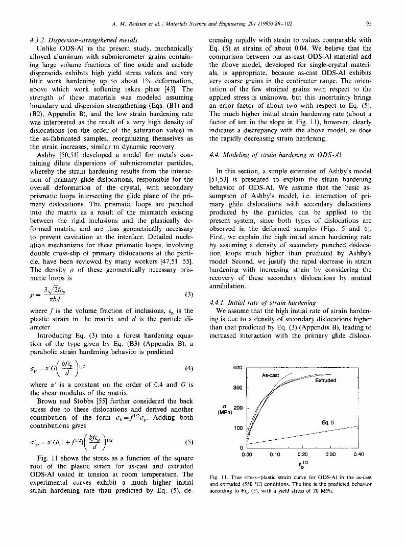
Fig. 11 shows the stress as a function of the square root of the plastic strain for as-cast and extruded ODS-Al tested in tension at room temperature. The experimental curves exhibit a much higher initial strain hardening rate than predicted by Eq. (5), de-
creasing rapidly with strain to values comparable with Eq. (5) at strains of about 0.04. We believe that the comparison between our as-cast ODS-Al material and the above model, developed for single-crystal materi- als, is appropriate, because as-cast ODS-Al exhibits very coarse grains in the centimeter range. The orien- tation of the few strained grains with respect to the applied stress is unknown, but this uncertainty brings an error factor of about two with respect to Eq. (5). The much higher initial strain hardening rate (about a factor of ten in the slope in Fig. 1 l), however, clearly indicates a discrepancy with the above model, as does the rapidly decreasing strain hardening.
4.4. Modeling of strain hardening in ODS-AI
In this section, a simple extension of Ashby’s model [51,53] is presented to explain the strain hardening behavior of ODS-Al. We assume that the basic as- sumption of Ashby’s model, i.e. interaction of pri- mary glide dislocations with secondary dislocations produced by the particles, can be applied to the present system, since both types of dislocations are observed in the deformed samples (Figs. 5 and 6). First, we explain the high initial strain hardening rate by assuming a density of secondary punched disloca- tion loops much higher than predicted by Ashby’s model. Second, we justify the rapid decrease in strain hardening with increasing strain by considering the recovery of these secondary dislocations by mutual annihilation.
4.4.1. Initial rate of strain hardening We assume that the high initial rate of strain harden-
ing is due to a density of secondary dislocations higher than that predicted by Eq. (3) (Appendix B), leading to increased interaction with the primary glide disloca-
400 , I
300
(J 200 WW
100
Fig. 11. True stress-plastic strain curve for ODS-AI in the as-cast and extruded (550 “C) conditions. The line is the predicted behavior according to Eq. (5), with a yield stress of 20 MPa.

96 A. M. Redsten et al. / Materials Science and Engineering 201 (1995) 88-102
tions. Two possible mechanisms can be proposed for an increased density of secondary dislocations, both of which rely on the larger size of the particles compared with the small dispersoids considered in Ashby’s model. First, the matrix already contains dislocations before deformation as a result of the punching of prismatic loops due to the thermal mismatch on cooling (Fig. 4) the density of which is given by Eq. (B4) (Appendix B). These dislocations are only expected to be punched by particles with a diameter above the critical value d* (Eq. (l)), and were therefore not considered in Ashby’s model, which describes particles with diameters below this threshold. Entanglement is expected on interaction between these prismatic loops punched by thermal mis- match (which are of interstitial character and are ex- pected to be punched along all glide directions) and the prismatic loops punched by deformation mismatch (which are both interstitial and vacancy in character and are punched preferentially along the directions of maximum strain mismatch). As a result of entangle- ment between these loops, dislocation multiplication can take place and the total density of secondary dislocations is above that given in Eq. (3), with the result that the initial strain hardening is higher (Eq. (4)). Entanglement has also been observed around large particles punching prismatic loops on CTE mismatch [56,57] or bulk modulus mismatch [%I. The above hypothesis is also supported indirectly by the observa- tion of Humphreys [38], who reported that unalloyed aluminum containing 17 vol.% Sic particles, 3 urn in diameter, exhibits greater rates of strain hardening after quenching than after furnace cooling; on quenching, the rate of dislocation punching is much higher, and thus the probability of entanglement leading to disloca- tion multiplication is increased.
Another possible explanation for an increased sec- ondary prismatic loop density also takes into account the large size of the particles. In Ashby’s model [51,53], the diameter of the prismatic loops is assumed to ‘be comparable with that of the particles, since the pris- matic loops form by cross-slip of the screw components of a shear loop along the cylinder of maximum shear stress [52,59]. This assumption is justified by numerous TEM observations of deformed metals containing small dispersoids [51,58,59]. However, as the particle diame- ter increases, the probability increases that the screw components will encounter an obstacle before complet- ing a loop of maximum radius r, interrupting the process and leading to a smaller loop. The net result is that a single large loop of radius r is replaced by numerous prismatic loops with a smaller radius r’, but a larger total length than the single prismatic loop of radius r. Assuming that the total area of loops is constant, the secondary prismatic loop density is then
p’=pr r’
Furthermore, an increased dislocation density is ex- pected if the particle exhibits stress concentrators, such as sharp corners, which also punch loops of smaller diameters [57]. Indeed, Fig. 5 shows that the disloca- tions found around the particles are significantly smaller than the particle diameter.
Although the observed increase in the slope a,/~“~ by a factor of about ten for ODS-Al is high (Fig. 11) it is plausible: it corresponds to an increase in the punched dislocation length by a factor of about 100 (i.e. a decrease in the average loop diameter by the same factor, Eq. (6)) or an increase in the dislocation density by entanglement by a factor of 100, or a combination of these mechanisms.
4.4.2. Strain dependence of strain hardening We assign the steep decrease in strain hardening with
increasing strain to the recovery of secondary disloca- tion loops, as also reported by Ashby [51,53]. One mechanism for dislocation recovery discussed by Ashby is cavitation. Cavitation is expected to occur at decreas- ing strains, as the size of the particle increases, and may thus be responsible for the observed decrease in strain hardening in ODS-Al. However, no evidence of cavita- tion was found during TEM observation of ODS-Al, indicating that this effect is probably negligible. Ashby also considered the recovery of pairs of prismatic loops of interstitial and vacancy nature, punched on opposite sides of a particle: the diffusion of atoms or vacancies leads to the annihilation of the pair. The rate of this recovery mechanism decreases with increasing diffusion distance and thus with increasing particle diameter. The strain rate i, at which recovery by annihilation and generation by punching are equal is 1511
2Db GR 3==d’ (7)
where D is the diffusion coefficient, R is the atomic volume, k is Boltzmann’s constant and T is the temper- ature. Using material values for aluminum given by Frost and Ashby [41], Eq. (7) predicts a critical strain rate of about 2 x lo- l7 SK’, i.e.. much smaller than the experimental strain rate of 8 x 10 -‘. We conclude that recovery by diffusion around particles with a diameter of 0.28 urn is negligible in aluminum at room tempera- ture.
Instead, we propose a different recovery mechanism, also based on the annihilation of prismatic loops of opposite sign. Whereas Ashby [51,53] considered the interaction of loops of opposite sign on opposite sides of the same particle, annihilating each other by diffu- sional mass transport, we consider the annihilation of prismatic loops of opposite sign from neighboring par-
A. M. Redsten et al. / Materials Science and Engineering 201 (1995) 88-102 97
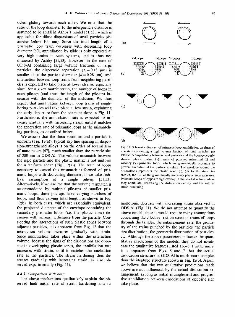
titles, gliding towards each other. We note that the ratio of the loop diameter to the interparticle distance is assumed to be small in Ashby’s model [51,53], which is applicable for dilute dispersions of small particles (di- ameter below 100 nm). Since the total length of a prismatic loop train decreases with decreasing loop diameter [60], annihilation by glide is only expected at very high strains in such systems, and is thus not discussed by Ashby [51,53]. However, in the case of ODS-Al containing large volume fractions of large particles, the dispersoid separation (L = 0.18 urn) is smaller than the particle diameter (d= 0.28 l.trn), and interaction between loop trains from neighboring parti- cles is expected to take place at lower strains, especially since, for a given matrix strain, the number of loops in each pile-up (and thus the length of the pile-up) in- creases with the diameter of the inclusion. We thus expect that annihilation between loop trains of neigh- boring particles will take place at low strain, explaining the early departure from the constant slope in Fig. 11. Furthermore, the annihilation rate is expected to in- crease gradually with increasing strain, until it matches the generation rate of prismatic loops at the mismatch- ing particles, as described below.
We assume that the shear strain around a particle is uniform (Fig. 12(a)): typical slip line spacing in disper- sion-strengthened alloys is on the order of several tens of nanometers [47], much smaller than the particle size of 280 nm in ODS-Al. The volume mismatch between the rigid particle and the plastic matrix is not uniform for a uniform shear (Fig. 12(a)). The train of loops necessary to cancel this mismatch is formed of pris- matic loops with decreasing diameter, if we take Ash- by’s assumption of a single pile-up [51,53]. Alternatively, if we assume that the volume mismatch is accommodated by multiple pile-ups of smaller pris- matic loops, these pile-ups have varying numbers of loops, and thus varying total length, as shown in Fig. 12(b). In both cases, which are essentially equivalent, the projected diameter of the envelope containing the secondary prismatic loops (i.e. the plastic zone) de- creases with increasing distance from the particle. Con- sidering the interactions of such plastic zones between adjacent particles, it is apparent from Fig. 12 that the interaction volume increases gradually with strain. Since annihilation takes place within the interaction volume, because the signs of the dislocations are oppo- site in overlapping plastic zones, the annihilation rate increases with strain, until it matches the nucleation rate at the particles. The strain hardening thus de- creases gradually with increasing strain, as also ob- served experimentally (Fig. 11).
4.4.3. Comparison with data The above mechanisms qualitatively explain the ob-
served high initial rate of strain hardening and its
(4
(b)
/ /
0 0 / /
V-Loops I-loops vL0ops
(cl vo’o’
Fig. 12. Schematic diagram of prismatic loop annihilation on shear of a matrix containing a high volume fraction of rigid particles. (a) Elastic incompatibility between rigid particles and the homogeneously strained plastic matrix. (b) Trains of punched interstitial (I) and vacancy (V) prismatic loops, which are geometrically necessary to prevent cavitation at the particle interface. The envelope around the dislocations represents the plastic zone. (c), (d) As the strain in- creases, the size of the geometrically necessary plastic zone increases. Prismatic loops of opposite sign overlap in the shaded volume where they annihilate, decreasing the dislocation density and the rate of strain hardening.
monotonic decrease with increasing strain observed in ODS-Al (Fig. 11). We do not attempt to quantify the above model, since it would require many assumptions concerning the effective friction stress of trains of loops through the tangles, the entanglement rate, the geome- try of the trains punched by the particles, the particle size distribution, the geometric distribution of particles, etc. Although the above parameters influence the quan- titative predictions of the models, they do not invali- date the qualitative features listed above. Furthermore, it is apparent from Figs. 6 and 7 that the actual dislocation structure in ODS-Al is much more complex than the idealized structure shown in Fig. 12(b). Again, we believe that the two qualitative predictions made above are not influenced by the actual dislocation ar- rangement, as long as initial entanglement and progres- sive annihilation between dislocations of opposite sign take place.
98 A. M. Redsten et al. / Materials Science and Engineering 201 (1995) 88-102
As seen in Fig. 11, the strain hardening behavior of extruded, fine-grained ODS-Al is not significantly different from that of as-cast, coarse-grained ODS-Al. Grain boundaries are obstacles for the motion of pri- mary glide dislocations and thus may affect the yield strength (Eq. (B2), Appendix B). The strengthening contribution of grain boundaries is, however, constant with strain, and is thus not expected to influence the strain hardening. A possible indirect contribution, which may vary with strain, consists of dislocations produced as a result of strain incompatibilities between adjacent grains. This contribution seems, however, to be negligible in the case of ODS-AI. Finally, we note that the dislocation structure of as-cast ODS-Al is quite different from that of extruded ODS-Al: unlike the latter samples, a well-developed subgrain structure is observed in the former samples. This may be explained by the fact that the grain size of the extruded samples is on the order of the subgrain size found in deformed aluminum [61] and thus subgrain formation is inhibited.
4.5. Fracture
The measured fracture toughness of as-cast ODS-Al (K,o = 18 MPa m1’2) is similar to that of cast or ex- truded aluminum matrix composites with comparable volume fractions of reinforcement [31]. The ductility of extruded ODS-Al (9.4%-l l%, Table 1) is also com- parable with that reported by Humphreys et al. [28] for extruded pure aluminum with 25 vol.% Sic fabricated by powder metallurgy: these workers found ductilities of 13% for particles sizes of 3, 7 and 20 urn, decreasing to 8% for 40 urn particles and 5% for 100 urn particles. The lower ductility values found in the as-cast ODS-Al (4.7%, Table 1) is probably the result of the higher extent of particle clustering (Fig. 2): regions with locally higher volume fractions of reinforcement exhibit a lower ductility and control the overall ductility of the composite [62]. The large spread of values (varying between 3.2% and 6%) can be attributed, at least in one instance, to a large (1 mm) solidification defect which initiated premature failure, suggesting that the ductility of the as-cast materials is sensitive to particle distribu- tion and processing conditions. Subsequent extrusion leads to improved particle distribution and reduction of these casting inhomogeneities.
The microdimples observed on both the as-cast and extruded fracture surfaces (Fig. 7(b)) are typical for dispersion-strengthened materials, and suggest that fracture occurs by nucleation and growth of voids at particles, and by plastic deformation of the elongated ridges at the rim of the dimples [63]. On a larger scale, the zig-zag fracture path, observed in extruded ODS- Al, has also been found in aluminum alloys (but not in pure aluminum) [64,65], copper [66], maraging steels [67] and titanium and cobalt alloys [64]. The peak-to-
peak spacing (50-100 urn) of the zig-zag front of our material is within the range reported for the materials above, i.e. from 10 urn [68] to 800 urn [67]. According to Van Den Avyle [65], the features common to all these materials are: (i) the presence of 0.05-0.5 urn second-phase particles with a spacing-to-diameter ratio on the order of 10 to 1; (ii) fracture by microvoid initiation, growth and coalescence on ridges; (iii) mod- erate to high fracture toughness of the alloy; (iv) a high degree of triaxiality ahead of the crack tip; (v) plane strain conditions ahead of the crack tip. Features (i)- (iii) are indeed observed in ODS-Al.
To explain zig-zag fracture, McClintock [69] pro- posed a combined Mode I-Mode II fracture criterion which predicts crack propagation along the line sepa- rating the regions of high hydrostatic stress (in front of the crack tip) and high shear strain (above and below the crack front). These predictions are made for a non-propagating sharp crack in a non-hardening mate- rial: strain hardening increases the stress concentration in the near-tip region and crack tip blunting affects both the spacing and the angle of the zig-zag path. Since strain hardening is very low when the ODS-Al samples fracture (Fig. ll), the non-hardening case can be applied. The zig-zag crack is then proposed to propagate in the following sequence [65]: (i) the crack begins to grow within the macroscopic plastic zone at a 45” angle to the macroscopic crack plane, following a line of constant hydrostatic-stress; (ii) when the crack reaches a point where the combined critical hydrostatic stress/shear strain criterion is lower along the 45” path than the competing strain field of another perpendicu- lar slip line also 45” to the macroscopic plane, the crack changes direction and moves towards the macroscopic crack plane; (iii) the crack follows this slip line until the process is repeated.
4.6. High-temperature strength
Fig. 9 shows that the proof and ultimate stresses for the ODS materials decrease linearly with temperature between 20 and 260 ‘C, and that solid solution strengthening of the matrix improves the elevated tem- perature strength. A similar decrease was found for unalloyed aluminum MMCs with 20 vol.% Sic particles tested in compression [70]; furthermore, the flow stress was found to decrease at all temperatures with increas- ing particle size (1, 3 and 20 urn). This is expected for MMCs with large particles, since most of their strength is derived from dislocation punching (Eq. (B4), Ap- pendix B): the strength is expected to decrease rapidly at elevated temperature, due to matrix creep (reducing the matrix yield stress) and dislocation annealing (as a result of recovery and recrystallization). However, in aluminum containing smaller dispersoids, for which dispersion strengthening (Eq. (Bl), Appendix B) and
A. M. Redsten et al. / Materials Science and Engineering 201 (1995) 88-102 99
boundary strengthening (Eq. (B2), Appendix B) become important, the strengthening mechanisms are still oper- ative at elevated temperature for dislocation-glide-con- trolled flow, albeit to a lesser extent than at low temperature, due to diffusion and climb processes [71,72] and a decrease in elastic modulus. As shown by the annealing experiments, the fine grain size of ex- truded ODS-Al is exceptionally stable, since only a slight increase in grain size was found after annealing for 139 h at a homologous temperature of 0.99. A decrease in reinforcement size is thus expected to bring a higher strength at elevated temperature due to boundary strengthening, provided that grain boundary sliding is inhibited by the high volume fraction of particles, as observed in many mechanically alloyed aluminum alloys and SAP [7,73,74] materials.
Fig. 8 shows that the hardness also decreases with temperature. However, ODS-Al is harder than the pre- cipitation-strengthened alloy 6061 at all temperatures, especially above about 225 “C, where precipitate disso- lution and coarsening take place in Al-6061. Compared with the hardness values of the rapidly solidified, high- temperature alloy AA-8009 (Al-8Fe- 1 V- 1.2Si), unal- loyed ODS-Al is softer, but shows a similar temperature dependence. The data shown in Fig. 8 suggest that ODS-Al retains useful strength values up to 450 “C. For example, at 465 “C (corresponding to a homologous temperature of 0.79), the hardness of ODS-Al is HV = 173 MPa, which, using the conversion HV = 3UTS, corresponds to an ultimate tensile strength (UTS) value of 58 MPa. This conversion is found to hold reasonably well for the UTS values of extruded ODS-Al measured at lower temperatures (Table l), as shown by the converted UTS values plotted as open symbols in Fig. 8.
5. Conclusions
(1) Binder-free preforms with 0.1-0.4 urn a-alumina particles were pressure infiltrated with liquid alu- minum (99.9% Al or Al-2.5%Mg), resulting in pore-free ODS-Al containing 25 vol.% alumina par- ticles, which are neither sintered nor coarsened. The particle size is smaller than that of most MMCs, but larger than that of typical precipitation-hard- ened, rapidly solidified or mechanically alloyed alu- minum alloys.
(2) The grain size of ODS-Al can vary from millimeters in the as-cast condition to micrometers in the ex- truded, recrystallized condition. Grain growth is negligible at temperatures as high as 650 “C.
(3) The Young’s modulus of ODS-AlMg is 110 GPa, as predicted from continuum mechanics models as- suming elastic stress transfer without interfacial debonding.
(4) The room temperature yield stress is low (on the order of 60 MPa), but high strain hardening rates lead to high values of the 0.2% proof stress (170 MPa and 215 MPa) and ultimate tensile strength (330 and 340 MPa) for as-cast and extruded ODS- Al respectively. The room temperature ductilities are 5% and 10% respectively. Matrix alloying im- proves the strength but decreases the ductility.
(5) The initial strain hardening 6f ODS-Al is much higher than that predicted by Ashby’s model [51,53], developed for small volume fractions of small dispersoids, whereby primary glide disloca- tions interact with secondary prismatic loops punched by the particles as a result of strain mis- match. Two additional mechanisms are proposed within the framework of Ashby’s model, taking into account the large particle size representative of ODS-Al: entanglement of the primary dislocations with (i) prismatic loops produced by thermal mis- match or (ii) prismatic loops produced by strain mismatch, with a diameter smaller, and thus a density larger, than those considered by Ashby. For both mechanisms, the interaction with glide disloca- tions is enhanced, thus explaining the high initial strain hardening observed in ODS-Al.
(6) The strain hardening of ODS-Al decreases rapidly with increasing strain. The interaction of prismatic loops punched from adjacent particles is proposed as a relaxation mechanism. Since the loops are of opposite sign in adjacent plastic zones, they annihi- late with increasing frequency as the overlap be- tween the plastic zones increases with strain. This assumption stems from the small interparticle dis- tance compared with the particle diameter, i.e. from the large volume fraction of particles.
(7) The strength of ODS-Al decreases with increasing temperature from 20 to 260 “C. The hardness data suggest that strength values on the order of 60 MPa are retained at temperatures up to 460 “C, as a result of dispersion strengthening.
Acknowledgments
A.M.B. and E.M.K. acknowledge support from the National Science Foundation (NSF) in the form of a Small Business Innovation Research (SBIR) grant (IS1 91-60518) to Chesapeake Composites Corporation. A.M.R. and D.C.D. acknowledge the support of the Department of Defence (DOD) (in the form of a Na- tional Defense Science and Engineering Graduate (ND- SEG fellowship) and AMAX (in the form of an endowed chair at the Massachusetts Institute of Tech- nology (MIT)) respectively. The authors are grateful to Dr. W. Hunt (Alcoa) for room temperature mechanical testing and optical microscopy of the as-cast material
100 A. M. Redsten et al. / Materials Science and Engineering 201 (1995) 88-102
and Dr. R. Wills (TRW) and Dr. M. Zedalis (Allied Signal) for elevated temperature tensile testing of ex- truded ODS-Al and ODS-AlMg respectively.
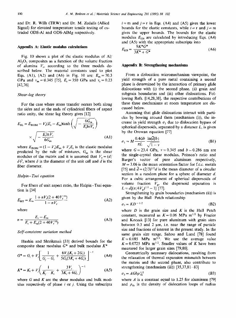
Appendix A: Elastic modulus calculations
Fig. 10 shows a plot of the elastic modulus of Al/ A&O, composites as a function of the volume fraction of alumina I’,, according to the three models de- scribed below. The material constants used to plot Eqs. (Al), (A2) and (A6) in Fig. 10 are: E,,, = 70.3 GPa and v, = 0.345 [75], E,= 350 GPa and v,= 0.23 [42,76].
Shear-lag theory
For the case where stress transfer occurs both along the sides and at the ends of cylindrical fibers of aspect ratio unity, the shear lag theory gives [12]
X i E,ln K
v 6Grn \ I
where ERoM = (1 - VJE, + V,E, is the elastic modulus predicted by the rule of mixtures, G, is the shear modulus of the matrix and it is assumed that V, = (d/ S)3, where S is the diameter of the unit cell and d is the fiber diameter.
Halpin- Tsai equation
For fibers of unit aspect ratio, the Halpin-Tsai equa- tion is [34]
E _E 1 +nVr(2+40Vr10) WI-- m 1 -nV,
where
-Q-Em n = E, + E,(2 + 40 V,“)
6421
(A3)
Self-consistent variation method
Hashin and Shtrikman [33] derived bounds for the composite shear modulus G* and bulk modulus K*
6 y.(Ki + 2Gi) - ’ 5Gi(3Ki + 4Gi) 1 (A4)
K*=K,+ 5 (
1 ,Kj-K,
+ 3 v;
jKi + 4Gi
-1
(A5)
where G and K are the shear modulus and bulk mod- ulus respectively of phase i or j. Using the subscripts
i = m and j = r in Eqs. (A4) and (A5) gives the lower bounds for the elastic constants, while i = r and j = m gives the upper bounds. The bounds for the elastic modulus EHs are calculated by introducing Eqs. (A4) and (A5) with the appropriate subscripts into
EHS = 9K*G*
3K* + G* G-46)
Appendix B: Strengthening mechanisms
From a dislocation micromechanism viewpoint, the yield strength of a pure metal containing a second phase is determined by the interaction of primary glide dislocations with (i) the second phase, (ii) grain and subgrain boundaries and (iii) other dislocations. Fol- lowing Refs. [14,28,38-j, the respective contributions of these three mechanisms at room temperature are dis- cussed below.
Assuming that glide dislocations interact with parti- cles by bowing around them (mechanism (i)), the in- crease in yield strength 0, due to dislocation bypass of spherical dispersoids, separated by a distance L, is given by the Orowan equation [77]
~ I
= M 0.4Gb ln@/b) -___ (Bl) nL 41-v
_ I
where G = 23.4 GPa, v = 0.345 and b = 0.286 nm are the single-crystal shear modulus, Poisson’s ratio and Burger’s vector of pure aluminum respectively, M = 3.06 is the mean orientation factor for f.c.c. metals [75] and ;i= (2/3)“‘d is the mean diameter of a circular section in a random plane for a sphere of diameter d. For a cubic arrangement of spherical dispersoids of volume fraction VP, the dispersoid separation is L = d[(x/4VJ”* - l] [77].
Strengthening by grain boundaries (mechanism (ii)) is given by the Hall-Petch relationship
g2 = KD ~ ‘I* (B2) where D is the grain size and K is the Hall-Petch constant, measured as K = 0.06 MPa ml’* by Frazier and Koczak [13] for pure aluminum with grain sizes between 0.3 and 2 urn, i.e. near the range of particle size and fractions of interest in the present study. In the same grain size range, Sahoo and Lund [78] found K= 0.085 MPa ml’*. We use the average value K = 0.0725 MPa ml’*, Smaller values of K have been measured for larger grain sizes [79,80].
Geometrically necessary dislocations, resulting from the relaxation of thermal expansion mismatch between the matrix and the second phase, also contribute to strengthening (mechanism (iii)) [35,37,8 l-831
CS, = A Gbp :L2 (B3) where A is a constant equal to 1.25 for aluminum [79] and pt,, is the density of dislocation loops of radius

A. M. Redsten et al. / Materials Science and Engineering 201 (1995) 88-102 101
d/J2 punched by spherical particles of diameter d, assuming full relaxation of the mismatch due to the difference in thermal expansion coefficients Aa for a temperature excursion AT [40]
Pth = 12$AaATV,,
bd(1 -V,) (B4)
For the system Al/A&O,, we take Aa = 1.5 x 10 - 5 K ~ ’ and AT = 250 K. The latter parameter is chosen so that the upper temperature at which dislocation punch- ing is assumed to begin is T,,, = 550 K, corresponding to a homologous temperature of 0.59. Above T,,,, all mismatch is assumed to be relaxed by diffusion, as also observed for quenched AgCl containing glass spheres at hpmologous temperatures of 0.55 f 0.04 [40].
For the experimental parameters V, = 0.25, d = 0.28 pm and D = 1.4 urn (for the sample extruded at 550 “C) or D = 1 cm (for the as-cast samples), the three strength- ening mechanisms described above are: o‘l = 121 MPa (Orowan strengthening, Eq. (Bl)), rr2 = 61 MPa for the extruded sample and rr2 = 1 MPa for the as-cast sample (Hall-Petch strengthening, Eq. (B2)) and cr3 = 136 MPa (forest strengthening, Eqs. (B3) and (B4)).
References
111
[21
131
141
[51 [61 [71 [81
[91
1101
1111
[I21
U31
H41
[I51
C.R. Brooks, Heat Treatment, Structure and Properties of Non- ferrous Alloys, American Society for Metals, Metals Park, OH, 1982, pp. 11551374. LJ. Polmear, Light Alloys: Metallurgy of the Light Metals, Edward Arnold, London, 1989, pp. 188168. J.M. Sater, SC. Jha and T.H. Sanders, Jr., in A.K. Vaseduvan and R.D. Doherty (eds.), Aluminum Alloys~Contemporary Re- search and Applications, Academic Press, Boston, MA, 1989, pp. 4099444. F.H. Froes, Y.-W. Kim, S. Krishnamurthy and R. Sundaresan, in I. Jenkins and J.V. Wood (eds.), Powder MetaNurgy: an Overview, The Institute of Metals, London, 1991, pp. 220-255. W.M. Doyle, Sheet Met. Ind., 32 (1955) 889.
E.A. Bloch, Metall. Rev., 6 (1961) 193. N. Hansen, Powder Metall., IO (1967) 95. J.S. Benjamin and M.J. Bomford, Metall. Trans. A, 8 (1977) 1301. V. Arnhold and J. Baumgarten, Powder MetaN. Int., 17 (1985) 168. J.H. Weber and R.D. Schelleng, in Y.-W. Kim and W.M. Griffith (eds.), Dispersion Strengthened Aluminum Alloys, TMS, Warrendale, PA, 1988, pp. 467-482. R. Sundaresan and F.H. Froes, in E. Arzt and L. Schultz (eds.), New Materials by Mechanical Alloying Techniques, DGM Ver- lag, Oberursel, 1989, pp. 243-263. M. Taya and R.J. Arsenault, Metal Matrix Composites: Ther- momechanical Behavior, Pergamon, Oxford, 1989, pp. 49-l 12. W.E. Frazier and M.J. Koczak, in Y.-W. Kim and W.M. Griffith (eds.), Dispersion Strengthened Aluminum Alloys, TMS, Warren- dale, PA, 1988, pp. 573-602. W.S. Miller and F.J. Humphreys, Ser. Metall. Mater., 25 (1991) 33. D.C. Dunand and B. Derby, in S. Suresh, A. Mortensen and A. Needleman (eds.), Fundamentals of Metal Matrix Composites, Butterworth-Heinemann, Boston, MA, 1993, pp. 191-214.
U61 U71
S81 1191
1201
[211
[221
1231
1241 1251 WI
v71
P81
1291
[301
1311
1321 [331
[341 [351 1361 [371 1381
[391 [401
1411
~421
1431
1441
1451
A.L. Geiger and J.A. Walker, J. Met., 43 (1991) 8. M.J. Tan, L.H. Koh, K.A. Khor, F.Y.C. Boey, Y. Murakoshi and T. Sano, J. Mater. Process Technol., 37 (1993) 391. R.J. Arsenault, J. Compos. Tech. Res., 10 (1988) 140-145. S.J. Hong, P.W. Kao and C.P. Chang, Mater. Sri. Eng. A, 158 (1992) 195. H.C. Yi, A. Petric and W.W. Smeltzer, in V.A. Ravi, T.S. Srivatsan and J.J. Moore (eds.), Processing and Fabrication of Advanced Materials, Vol. III, TMS, Warrendale, PA, 1994, pp. 763-769. R.M. Aikin, Jr. and L. Christodoulou, Ser. Metaii. Mater., 25 (1991) 9. K. Shanker, R.A.L. Drew, L.T. Mavropoulos and P.G. Tsantri- zos, Composites, 23 (1992) 47. D. Muscat, K. Shanker and R.A.L. Drew, Mater. Sci. Technoi., 8 (1992) 971. J.E. Allison and G.S. Cole, J. Met., 45(1993) 19. A. Mortensen and I. Jin, fnt. Mater. Rev., 37 (1992) 101-128. J.E. Hatch, Aluminum: Properties and Physical Metallurgy, American Society for Metals, Metals Park, OH, 1984, p. 855. W.H. Cubberly et al. (eds.), Metals Handbook: Properties and Selection: Nonferrous Alloys and Pure Metals, American Society for Metals, Metals Park, OH, 1979. F.J. Humphreys, A. Basu and M.R. Djazeb, in D. Jut&Jensen. N. Hansen, T. Leffers, H. Lilholt, T. Lorentzen, AS. Pedersen, O.B. Pedersen and B. Ralph (eds.), Metal Matrix Composites- Processing, Microstructure and Properties, Ris0’ National Labo- ratory, Roskilde, Denmark, 1991, pp. 51-66. D.Y. Lee and D.E. Zupon, in Y.-W. Kim and W.M. Griffith (eds.), Dispersion Strengthened Aluminum Alloys, TMS, Warren- dale, PA, 1988, pp. 265-281. D.J. Skinner, in Y.-W. Kim and W.M. Griffith (eds.), Dispersion Strengthened Aluminum Alloys, TMS, Warrendale, PA, 1988, pp. 181-197. A. Mortensen, Fabrication of Particulate Reinforced Metal Com- posites, ASM International, Metals Park, OH, 1990, pp. 217- 233. H.J. Seemann, Metallurgy, 17 (1963) 997. Z. Hashin and S. Shtrikman, J. Mech. Phys. Solids, II (1963) 121. V.C. Nardone and K.M. Prewo, Ser. Metali., 20 (1986) 43. D. Dew-Hughes, Acta Metall., 8 (1960) 816. R.J. Arsenault, Mater. Sci. Eng., 64 (1984) 171. B. Derby and J.R. Walker, Ser. Metall., 22 (1988) 529. F.J. Humphreys, in S.I. Andersen, H. Lilholt and O.B. Pedersen (eds.), Mechanical and Physical Behavior of Metallic and Ceramic Composites: 9th Ris 0 International Symposium on Metallurgy and Materials Science, Ris@’ National Laboratory, Roskilde, Denmark, 1988, pp. 51-74. P.M. Hazzledine, Ser. Metall. Mater., 26 (1992) 57. D.C. Dunand and A. Mortensen, Acta Metall. Mater., 39 (1991) 127. H.J. Frost and M.F. Ashby, Deformation-Mechanism Maps: The Plasticity and Creep of Metals and Ceramics, Pergamon, Oxford, 1982, p. 166. J. Shackelford and W. Alexander (eds.), The CRC Materials Science and Engineering Handbook, CRC Press, Boca Raton. FL, 1992. J.A. Hawk and H.G.F. Wilsdorf, in J.B. Bilde-Sorensen (ed.), Materials Architecture: Proceedings of the 10th Ris P, Inter- national Symposium on Metallurgy and Materials Science. Risk National Laboratory, Roskilde, Denmark, 1989, pp. 371- 316. G. Bao, J.W. Hutchinson and R.M. McMeeking, Acta Metall. Mater., 39 (1991) 1871. J.W. Hutchinson and R.M. McMeeking, in S. Suresh, A. Mortensen and A. Needleman (eds.). Fundamentals of Metal

102 A. M. Redsten et al. / Materials Science and Engineering 201 (1995) 88-102
Matrix Composites, Butterworth-Heinemann, Boston, MA, [63] Metals Handbook: Fractography, American Society for Metals, 1993, pp. 158-173. Metals Park, OH, 1987.
[46] SF. Corbin and D.S. Wilkinson, in N. Hansen, D. Juul-Jensen, T. Leffers, H. Lilholt, T. Lorentzen, AS. Pedersen, O.B. Pedersen and B. Ralph (eds.), Metal Matrix Composites-Pro- cessing, Microstructure and Properties, Ris5 National Labora- tory, Roskilde, Denmark, 1991, pp. 283-290.
[47] F.J. Humphreys, Dislocations and Properties of Real Materials, The Institute of Metals, London, 1985, pp. 1755204.
[48] S.V. Kamat, A.D. Rollett and J.P. Hirth, Ser. Metall. Mater., 25 (1991) 27.
[64] J.W. Carson, K. Mills et al. (eds.), Ph.D. Thesis, Massachusetts Institute of Technology, Cambridge, MA, 1970.
[65] J.A. Van Den Avyle, K. Mills et al. (eds.),Ph.D. Thesis, Massa- chusetts Institute of Technology, Cambridge, MA, 1975.
[66] H.C. Rogers, Trans. AZME, 218 (1960) 498. [67] G.R. Yoder, Metali. Trans., 3 (1972) 1851. [68] CA. Berg, in M.F. Kanninen (ed.), Inelastic Behavior of Solids,
McGraw-Hill, New York, 1970.
[49] J.J. Lewandowski, D.S. Liu and C. Liu, Ser. Metall. Mater., 2.5 (1991) 21.
[69] F.A. McClintock, in AS. Argon (ed.), Physics of Strength and Plasticity, MIT Press, Cambridge, MA, 1969, pp. 307- 326.
[50] M.F. Ashby, Philos. Mag., 21 (1970) 399. [51] M.F. Ashby, in A. Kelly and R.B. Nicholson (eds.), Strengthen-
ing Methods in Crystals, Applied Science Publishers, London, 1970, pp. 137-192.
[52] P.B. Hirsch, J. Inst. Met., 86 (1957) 7. [53] M.F. Ashby, Second International Conference on the Strength of
Metals and Alloys, Pacific Grove, California, American Society for Metals, Metals Park, OH, 1970, pp. 507-541.
[54] L.M. Brown and W.M. Stobbs, Philos. Mag., 23 (1971) 1185. [55] L.M. Brown and W.M. Stobbs, Philos. Mag., 23 (1971)
1201. [56] D.C. Dunand and A. Mortensen, Ser. Metall. Mater., 25 (1991)
761.
[70] F.J. Humphreys, Mater. Sci. Eng. A, 135 (1991) 267. [71] W. Blum and B. Reppich, Creep Behavior of Crystalline Solids,
Pineridge Press, Swansea, 1985, p. 83. [72] E. Arzt, in S. Ochiai (ed.), Mechanical Properties of Metallic
Composites, Dekker, New York, 1994, pp. 205-223. [73] W.C. Oliver and W.D. Nix, Acta Metall., 30 (1982) 1335. [74] J. Rosier, R. Joos and E. Arzt, Metall. Trans. A, 23 (1992) 1521. [75] M.A. Meyers and K.K. Chawla, Mechanical Metallurgy: Princi-
ples and Applications, Prentice-Hall, Englewood Cliffs, NJ, 1984. [76] J.W. Soh and H.M. Lee, Ser. Metall. Mater., 27 (1992) 783. [77] L.M. Brown and R.K. Ham, in A. Kelly and R.B. Nicholson
(eds.), Strengthening Methodr in Crystals, Elsevier, Amsterdam, 1971, pp. 99135.
[57] DC. Dunand and A. Mortensen, Mater. Sci. Eng. A, 135 (1991) 179.
[58] M.F. Ashby, S.H. Gelles and L.E. Tanner, Philos. Mag., 19 (1969) 757.
[78] M. Sahoo and J.A. Lund, Metall. Trans., 4 (1973) 39. [79] N. Hansen, Acta MetaN., 25 (1977) 863. [80] R.P. Carreker, Jr. and W.R. Hibbard, Jr., Trans. AZME, 209
(1957) 1157. [59] F.J. Humphreys and P.B. Hirsch, Proc. R. Sot. London, Ser. A,
318 (1970) 73. [60] D.C. Dunand and A. Mortensen, Ser. Metall. Mater., 25 (1991)
607.
[81] R.J. Arsenault and N. Shi, Mater. Sci. Eng., 81 (1986) 175. [82] Z.Y. Ma, J. Bi, Y.X. Lu and Y.X. Gao, Ser. Metall. Mater., 29
(1993) 225.
[61] H.J. McQueen and J.E. Hackett, Metall. Trans., I (1970) 2997. [62] J.D. Embury, Metall. Trans. A, 16 (1985) 2191.
[83] R.J. Arsenault, in R.K. Everett and R.J. Arsenault (eds.), Metal Matrix Composites: Mechanisms and Properties, Academic Press, Boston, MA, 1991, pp. 79-100.