Mechanical Micromachining by Drilling, Milling and Slotting
26
8 Mechanical Micromachining by Drilling, Milling and Slotting T. Gietzelt and L. Eichhorn Karlsruhe Institute of Technology, Campus Nord, Institute for Micro Process Engineering, Karlsruhe, Germany 1. Introduction Micromachining is not only a simple miniaturization of processes using macroscopic tools. As a matter of fact, a lot of specific concerns have to be met for successful fabrication of microstructures. This chapter will be focussed on micromachining using geometrically determined cutting edges, namely on techniques like drilling, milling and slotting. These methods are very flexible. Compared to EDM, ECM or lithographic processes like LIGA, they can be applied to a wide range of materials, like polymers, metals and alloys as well as to some kinds of ceramics, possess a high material removal rate and allow a great degree of freedom concerning design. There are nearly no geometrical limitations and also 3D- structures can be manufactured easily. 2. Micromachining by geometrically determined cutting edges 2.1 Differences as compared to geometrically undefined cutting edges Micromachining techniques can be divided into two main categories: Processes working with undefined cutting edges e.g. grinding, honing, lapping, and processes are using defined cutting edges like drilling, milling and slotting. Especially grinding works at high cutting rates. Most of the cutting energy is transferred into heat and absorbed by the work piece [Kön99, Fri08]. The properties of the work piece can be altered or decreased by surface cracks and internal stress due to external forces as well as by microstructural changes due to excessive heat. Especially for micro grinding using small-diameter tools, extremely high numbers of revolutions are required to achieve a reasonable circumferential speed of up to more than 100 m/s. Compared to processes using defined cutting edges, the energy need is high and the material removal rate is comparably low. Nevertheless, especially for very hard materials like most ceramics where defined cutting edges do not work, grinding is a capable technique. However, since diamonds are used to machine the very hard ceramic materials, machining expenses can be a major cost factor for ceramic parts [War00]. When machining using geometrically determined cutting edges, the cutting energy is mostly used to overcome the cohesion forces of the machined material. The material removal rate is higher than for grinding and most of the heat is transferred to and removed with the chips. A good approximation for the removal of heat is, that 75% are transferred to www.intechopen.com
Transcript of Mechanical Micromachining by Drilling, Milling and Slotting
8
Mechanical Micromachining by Drilling, Milling and Slotting
T. Gietzelt and L. Eichhorn Karlsruhe Institute of Technology, Campus Nord,
Institute for Micro Process Engineering, Karlsruhe, Germany
1. Introduction
Micromachining is not only a simple miniaturization of processes using macroscopic tools. As a matter of fact, a lot of specific concerns have to be met for successful fabrication of microstructures. This chapter will be focussed on micromachining using geometrically determined cutting edges, namely on techniques like drilling, milling and slotting. These methods are very flexible. Compared to EDM, ECM or lithographic processes like LIGA, they can be applied to a wide range of materials, like polymers, metals and alloys as well as to some kinds of ceramics, possess a high material removal rate and allow a great degree of freedom concerning design. There are nearly no geometrical limitations and also 3D-structures can be manufactured easily.
2. Micromachining by geometrically determined cutting edges
2.1 Differences as compared to geometrically undefined cutting edges Micromachining techniques can be divided into two main categories: Processes working with undefined cutting edges e.g. grinding, honing, lapping, and processes are using defined cutting edges like drilling, milling and slotting. Especially grinding works at high cutting rates. Most of the cutting energy is transferred into heat and absorbed by the work piece [Kön99, Fri08]. The properties of the work piece can be altered or decreased by surface cracks and internal stress due to external forces as well as by microstructural changes due to excessive heat. Especially for micro grinding using small-diameter tools, extremely high numbers of revolutions are required to achieve a reasonable circumferential speed of up to more than 100 m/s. Compared to processes using defined cutting edges, the energy need is high and the material removal rate is comparably low. Nevertheless, especially for very hard materials like most ceramics where defined cutting edges do not work, grinding is a capable technique. However, since diamonds are used to machine the very hard ceramic materials, machining expenses can be a major cost factor for ceramic parts [War00]. When machining using geometrically determined cutting edges, the cutting energy is mostly used to overcome the cohesion forces of the machined material. The material removal rate is higher than for grinding and most of the heat is transferred to and removed with the chips. A good approximation for the removal of heat is, that 75% are transferred to
www.intechopen.com
Micromachining Techniques for Fabrication of Micro and Nano Structures
160
the chips formed, 18% migrate to the tool and 7% to the work piece [Kön90]. Hence, the work piece and its microstructure are not as affected as in the case of grinding. When rotating micro-sized tools, attention has to be paid in general to the response on
external loads by deformation. The load case and the reaction of the tool are very important
as regards the machining result. Especially in the case of rotating tools possessing two chip
flutes, the cross section is reduced. Load cases can be distinguished for different machining
processes:
In case of micro drilling, only a torsional moment acts on the tool. Depending on the length,
bending and buckling may be an issue.
Slotting is an appropriate way if the desired trench width is smaller than that of
commercially available end mills or for large aspect ratios where the stability of end mills
can be problematic. An additional advantage of slotting is that the tool may not be axially
symmetric. Hence, a better stability is accomplished and only bending acts on the tool. Tools
with optimized shapes and angles can be made using precision grinding machines e. g.
Ewag WS 11 [Ewa_Ws] with worn hard metal end mills made of ultra-fine grain carbides. A
disadvantage is the slow feed rate and, hence, a smaller material removal rate than in the
case of micro milling.
In the case of micro milling both torsion and bending act on the tool. Predominantly, micro
end mills are made of hard metal possessing two chip flutes. However, also tools made of
monocrystalline diamonds with only one cutting edge are used.
Hence, dynamic fatigue due to cyclic bending or vibrations and irregular load may be a
serious problem especially for two flute micro end mills. Characteristics like appropriate hard
metal substrate, manufacturing process affecting roughness and cracks in the surface, coating
technology and adapted tool shape will be discussed in Chapter 3 for micro end mills.
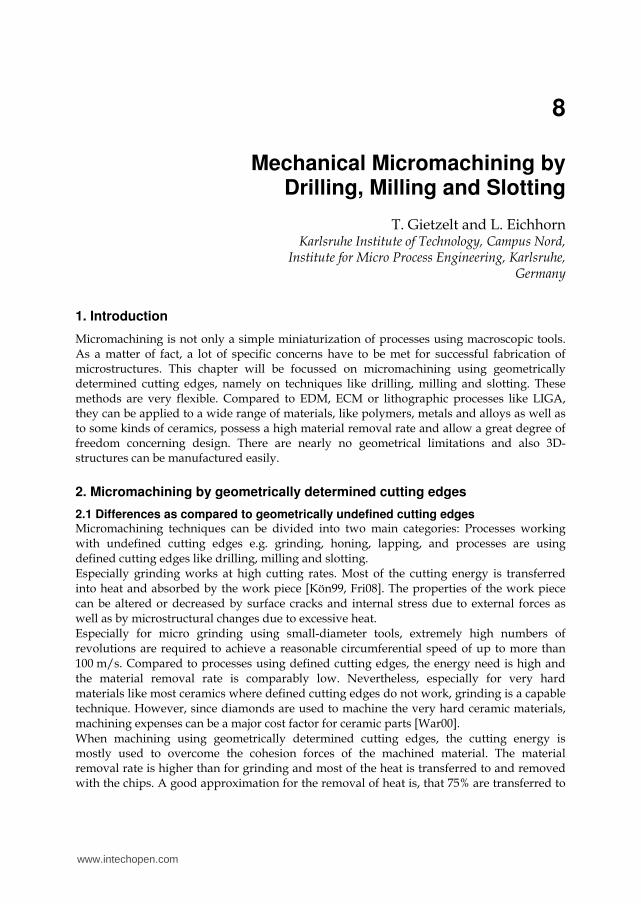
2.2 Geometrical limits of tools Micro drills originate from conductor board manufacturing for contacting through multiple layers. Although the prepregs used consist of a cured resin and very abrasive glass fibres, uncoated hard metal drills are used with good success. Uncoated micro drills are available down to diameters of 20 µm [Ato_Ad, Ham_38]. Fig. 1 shows a 30 µm micro drill bit.
Fig. 1. 30 µm micro drill bit with detail of the cutting edge. Grooves from grinding with jagged edge due to the composite nature of hard metal can be seen.
www.intechopen.com
Mechanical Micromachining by Drilling, Milling and Slotting
161
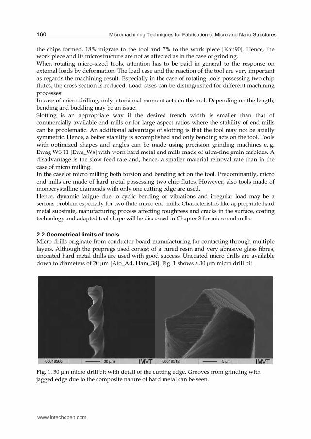
About five years ago, coating of micro end mills started only above 0.3 mm in diameter due to excessive rounding of the cutting edges by the coating layer. Up to this time, the gain of improved wear resistance due to the coating was less favourable than the increase of the cutting force due to the rounding of the cutting edge. Through improved coating process control, allowing thinner and more uniform layers, the relation was reversed. Today, coated micro mills down to 30 µm in diameter and with aspect ratios of 1.5 are commercially available [Hte_Em], (Fig. 2).
Fig. 2. Left: Coated 30 µm end mill made by Hitachi. Right: Top view.
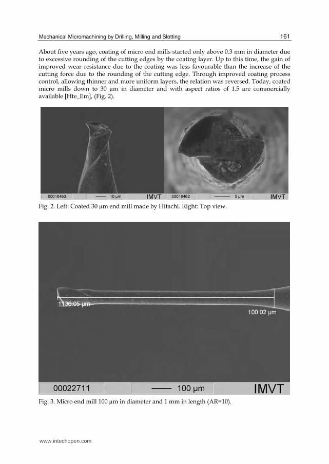
Fig. 3. Micro end mill 100 µm in diameter and 1 mm in length (AR=10).
www.intechopen.com
Micromachining Techniques for Fabrication of Micro and Nano Structures
162
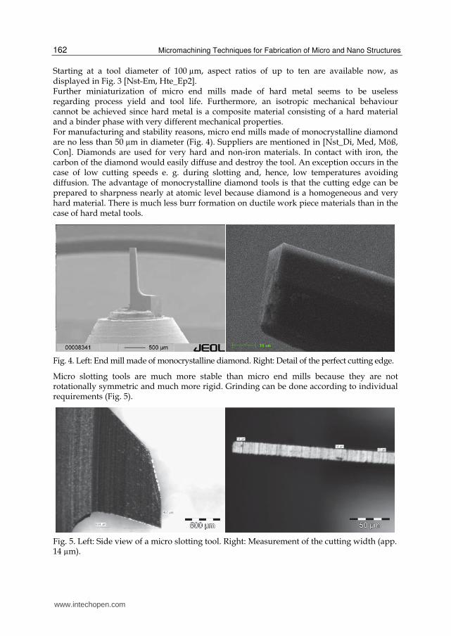
Starting at a tool diameter of 100 µm, aspect ratios of up to ten are available now, as displayed in Fig. 3 [Nst-Em, Hte_Ep2]. Further miniaturization of micro end mills made of hard metal seems to be useless regarding process yield and tool life. Furthermore, an isotropic mechanical behaviour cannot be achieved since hard metal is a composite material consisting of a hard material and a binder phase with very different mechanical properties. For manufacturing and stability reasons, micro end mills made of monocrystalline diamond are no less than 50 µm in diameter (Fig. 4). Suppliers are mentioned in [Nst_Di, Med, Möß, Con]. Diamonds are used for very hard and non-iron materials. In contact with iron, the carbon of the diamond would easily diffuse and destroy the tool. An exception occurs in the case of low cutting speeds e. g. during slotting and, hence, low temperatures avoiding diffusion. The advantage of monocrystalline diamond tools is that the cutting edge can be prepared to sharpness nearly at atomic level because diamond is a homogeneous and very hard material. There is much less burr formation on ductile work piece materials than in the case of hard metal tools.
Fig. 4. Left: End mill made of monocrystalline diamond. Right: Detail of the perfect cutting edge.
Micro slotting tools are much more stable than micro end mills because they are not rotationally symmetric and much more rigid. Grinding can be done according to individual requirements (Fig. 5).
Fig. 5. Left: Side view of a micro slotting tool. Right: Measurement of the cutting width (app. 14 µm).
www.intechopen.com
Mechanical Micromachining by Drilling, Milling and Slotting
163
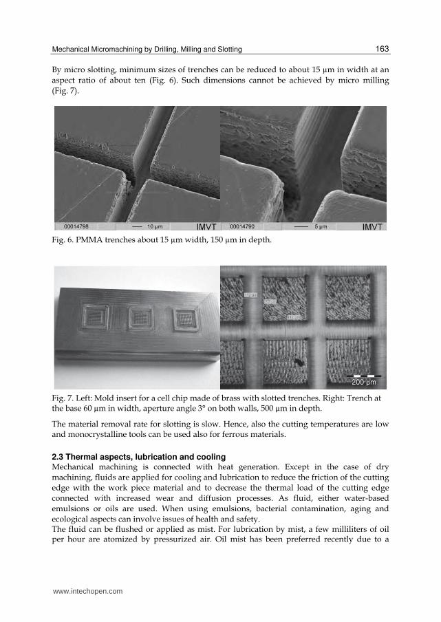
By micro slotting, minimum sizes of trenches can be reduced to about 15 µm in width at an
aspect ratio of about ten (Fig. 6). Such dimensions cannot be achieved by micro milling
(Fig. 7).
Fig. 6. PMMA trenches about 15 µm width, 150 µm in depth.
Fig. 7. Left: Mold insert for a cell chip made of brass with slotted trenches. Right: Trench at the base 60 µm in width, aperture angle 3° on both walls, 500 µm in depth.
The material removal rate for slotting is slow. Hence, also the cutting temperatures are low and monocrystalline tools can be used also for ferrous materials.
2.3 Thermal aspects, lubrication and cooling Mechanical machining is connected with heat generation. Except in the case of dry
machining, fluids are applied for cooling and lubrication to reduce the friction of the cutting
edge with the work piece material and to decrease the thermal load of the cutting edge
connected with increased wear and diffusion processes. As fluid, either water-based
emulsions or oils are used. When using emulsions, bacterial contamination, aging and
ecological aspects can involve issues of health and safety. The fluid can be flushed or applied as mist. For lubrication by mist, a few milliliters of oil per hour are atomized by pressurized air. Oil mist has been preferred recently due to a
www.intechopen.com
Micromachining Techniques for Fabrication of Micro and Nano Structures
164
number of advantages like reduced costs due to handling of smaller amounts of liquid, less storage and disposal costs, no hygienic problems due to bacterial contamination and less cleaning effort for liquid and the work piece. On the other hand, the right dosing of the oil in the air stream is essential especially in the case of micromachining to prevent the sticking of chips to the tool. The available apparatuses, however, lack in exact dosing systems. Sticking of chips leads to additional and fluctuating tool loads and can be an issue for tool failure. Additionally, the work piece surface quality is worse. For this reason, flush lubrication may be the better choice.
3. Tooling aspects: The role of material substrate, coating technology and tool shape
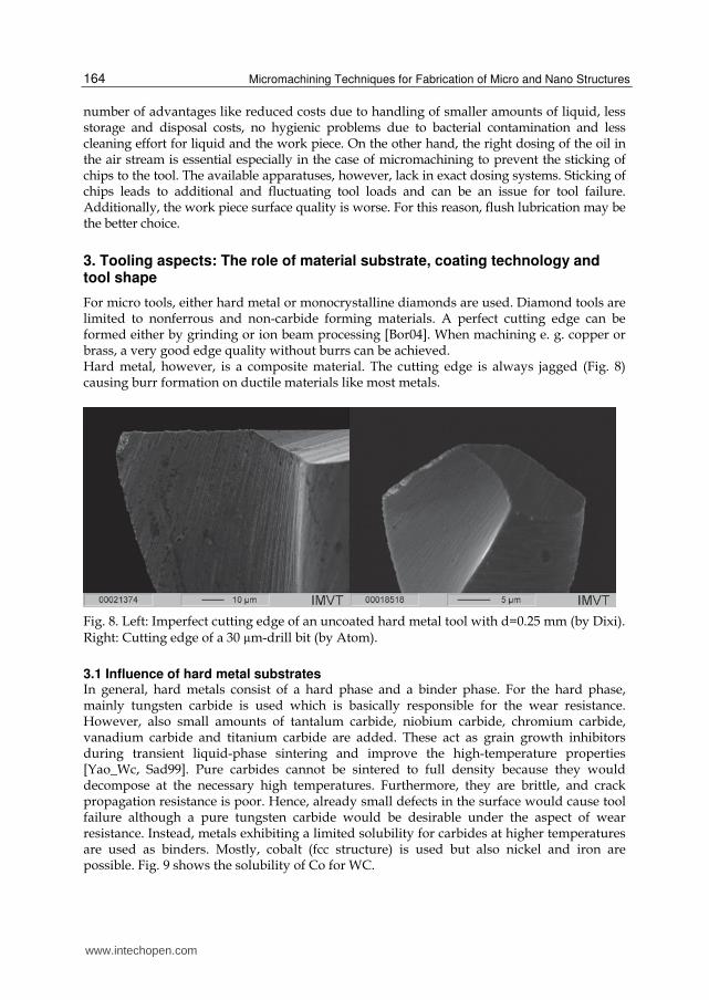
For micro tools, either hard metal or monocrystalline diamonds are used. Diamond tools are limited to nonferrous and non-carbide forming materials. A perfect cutting edge can be formed either by grinding or ion beam processing [Bor04]. When machining e. g. copper or brass, a very good edge quality without burrs can be achieved. Hard metal, however, is a composite material. The cutting edge is always jagged (Fig. 8) causing burr formation on ductile materials like most metals.
Fig. 8. Left: Imperfect cutting edge of an uncoated hard metal tool with d=0.25 mm (by Dixi). Right: Cutting edge of a 30 µm-drill bit (by Atom).
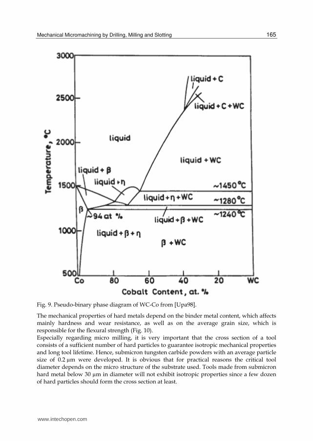
3.1 Influence of hard metal substrates In general, hard metals consist of a hard phase and a binder phase. For the hard phase, mainly tungsten carbide is used which is basically responsible for the wear resistance. However, also small amounts of tantalum carbide, niobium carbide, chromium carbide, vanadium carbide and titanium carbide are added. These act as grain growth inhibitors during transient liquid-phase sintering and improve the high-temperature properties [Yao_Wc, Sad99]. Pure carbides cannot be sintered to full density because they would decompose at the necessary high temperatures. Furthermore, they are brittle, and crack propagation resistance is poor. Hence, already small defects in the surface would cause tool failure although a pure tungsten carbide would be desirable under the aspect of wear resistance. Instead, metals exhibiting a limited solubility for carbides at higher temperatures are used as binders. Mostly, cobalt (fcc structure) is used but also nickel and iron are possible. Fig. 9 shows the solubility of Co for WC.
www.intechopen.com
Mechanical Micromachining by Drilling, Milling and Slotting
165
Fig. 9. Pseudo-binary phase diagram of WC-Co from [Upa98].
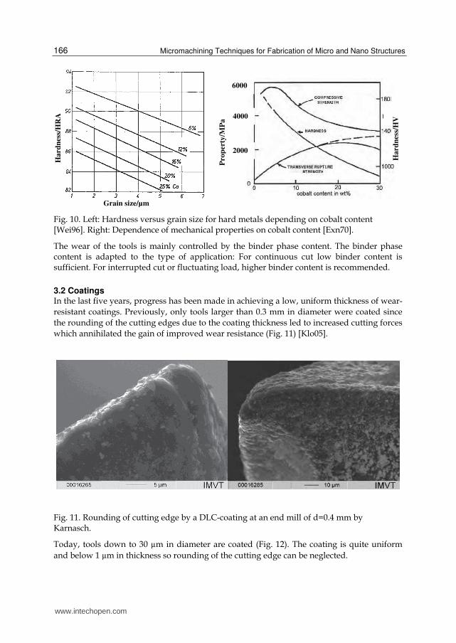
The mechanical properties of hard metals depend on the binder metal content, which affects mainly hardness and wear resistance, as well as on the average grain size, which is responsible for the flexural strength (Fig. 10). Especially regarding micro milling, it is very important that the cross section of a tool consists of a sufficient number of hard particles to guarantee isotropic mechanical properties and long tool lifetime. Hence, submicron tungsten carbide powders with an average particle size of 0.2 µm were developed. It is obvious that for practical reasons the critical tool diameter depends on the micro structure of the substrate used. Tools made from submicron hard metal below 30 µm in diameter will not exhibit isotropic properties since a few dozen of hard particles should form the cross section at least.
www.intechopen.com
Micromachining Techniques for Fabrication of Micro and Nano Structures
166
Fig. 10. Left: Hardness versus grain size for hard metals depending on cobalt content [Wei96]. Right: Dependence of mechanical properties on cobalt content [Exn70].
The wear of the tools is mainly controlled by the binder phase content. The binder phase content is adapted to the type of application: For continuous cut low binder content is sufficient. For interrupted cut or fluctuating load, higher binder content is recommended.
3.2 Coatings In the last five years, progress has been made in achieving a low, uniform thickness of wear-
resistant coatings. Previously, only tools larger than 0.3 mm in diameter were coated since
the rounding of the cutting edges due to the coating thickness led to increased cutting forces
which annihilated the gain of improved wear resistance (Fig. 11) [Klo05].
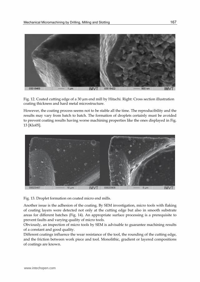
Fig. 11. Rounding of cutting edge by a DLC-coating at an end mill of d=0.4 mm by Karnasch.
Today, tools down to 30 µm in diameter are coated (Fig. 12). The coating is quite uniform
and below 1 µm in thickness so rounding of the cutting edge can be neglected.
Pro
per
ty/M
Pa
4000
2000
6000
Ha
rdn
ess/
HV
Ha
rdn
ess/
HR
A
Grain size/µm
www.intechopen.com
Mechanical Micromachining by Drilling, Milling and Slotting
167
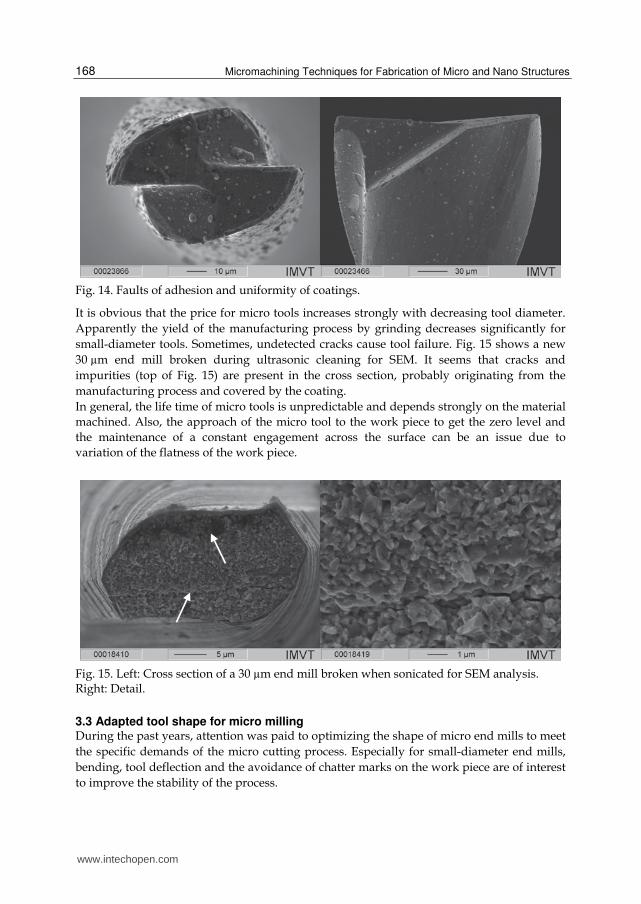
Fig. 12. Coated cutting edge of a 30 µm end mill by Hitachi. Right: Cross section illustration coating thickness and hard metal microstructure.
However, the coating process seems not to be stable all the time. The reproducibility and the
results may vary from batch to batch. The formation of droplets certainly must be avoided
to prevent coating results having worse machining properties like the ones displayed in Fig.
13 [Klo05].
Fig. 13. Droplet formation on coated micro end mills.
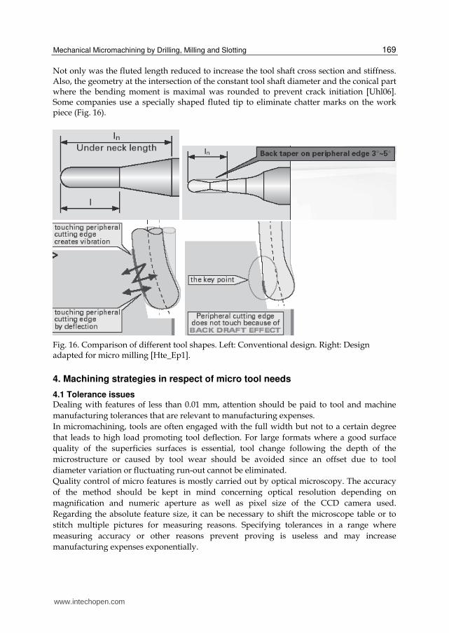
Another issue is the adhesion of the coating. By SEM investigation, micro tools with flaking
of coating layers were detected not only at the cutting edge but also in smooth substrate
areas for different batches (Fig. 14). An appropriate surface processing is a prerequisite to
prevent faults and varying quality of micro tools.
Obviously, an inspection of micro tools by SEM is advisable to guarantee machining results
of a constant and good quality.
Different coatings influence the wear resistance of the tool, the rounding of the cutting edge,
and the friction between work piece and tool. Monolithic, gradient or layered compositions
of coatings are known.
www.intechopen.com
Micromachining Techniques for Fabrication of Micro and Nano Structures
168
Fig. 14. Faults of adhesion and uniformity of coatings.
It is obvious that the price for micro tools increases strongly with decreasing tool diameter.
Apparently the yield of the manufacturing process by grinding decreases significantly for
small-diameter tools. Sometimes, undetected cracks cause tool failure. Fig. 15 shows a new
30 µm end mill broken during ultrasonic cleaning for SEM. It seems that cracks and
impurities (top of Fig. 15) are present in the cross section, probably originating from the
manufacturing process and covered by the coating.
In general, the life time of micro tools is unpredictable and depends strongly on the material
machined. Also, the approach of the micro tool to the work piece to get the zero level and
the maintenance of a constant engagement across the surface can be an issue due to
variation of the flatness of the work piece.
Fig. 15. Left: Cross section of a 30 µm end mill broken when sonicated for SEM analysis. Right: Detail.
3.3 Adapted tool shape for micro milling During the past years, attention was paid to optimizing the shape of micro end mills to meet
the specific demands of the micro cutting process. Especially for small-diameter end mills,
bending, tool deflection and the avoidance of chatter marks on the work piece are of interest
to improve the stability of the process.
www.intechopen.com
Mechanical Micromachining by Drilling, Milling and Slotting
169
Not only was the fluted length reduced to increase the tool shaft cross section and stiffness. Also, the geometry at the intersection of the constant tool shaft diameter and the conical part where the bending moment is maximal was rounded to prevent crack initiation [Uhl06]. Some companies use a specially shaped fluted tip to eliminate chatter marks on the work piece (Fig. 16).
Fig. 16. Comparison of different tool shapes. Left: Conventional design. Right: Design adapted for micro milling [Hte_Ep1].
4. Machining strategies in respect of micro tool needs
4.1 Tolerance issues Dealing with features of less than 0.01 mm, attention should be paid to tool and machine
manufacturing tolerances that are relevant to manufacturing expenses.
In micromachining, tools are often engaged with the full width but not to a certain degree
that leads to high load promoting tool deflection. For large formats where a good surface
quality of the superficies surfaces is essential, tool change following the depth of the
microstructure or caused by tool wear should be avoided since an offset due to tool
diameter variation or fluctuating run-out cannot be eliminated.
Quality control of micro features is mostly carried out by optical microscopy. The accuracy
of the method should be kept in mind concerning optical resolution depending on
magnification and numeric aperture as well as pixel size of the CCD camera used.
Regarding the absolute feature size, it can be necessary to shift the microscope table or to
stitch multiple pictures for measuring reasons. Specifying tolerances in a range where
measuring accuracy or other reasons prevent proving is useless and may increase
manufacturing expenses exponentially.
www.intechopen.com
Micromachining Techniques for Fabrication of Micro and Nano Structures
170
Mostly, quality control is carried out by optical microscopy only at the surface level by edge detection but not at a certain depth. Using tactile devices such as fiber probes [Wer], limitations according to their relevant dimensions must be taken into account. Generally, tolerances should be one order of magnitude larger than the measuring accuracy and the achievable roughness. Mostly, roughness values for the arithmetic average Ra or highest and lowest peaks within a certain distance like Rt are specified or predefined. With mechanical micro structuring, Ra-values are in the range of 0.2 µm. Typically for micro milling, Rt is 7-10 times higher than Ra, namely in the range of 1-2 µm.
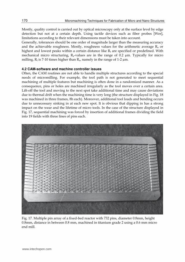
4.2 CAM-software and machine controller issues Often, the CAM routines are not able to handle multiple structures according to the special needs of micromilling. For example, the tool path is not generated to meet sequential machining of multiple features but machining is often done in a randomized manner. As a consequence, pins or holes are machined irregularly as the tool moves over a certain area. Lift-off the tool and moving to the next spot take additional time and may cause deviations due to thermal drift when the machining time is very long (the structure displayed in Fig. 18 was machined in three frames, 8h each). Moreover, additional tool loads and bending occurs due to unnecessary sinking in at each new spot. It is obvious that dipping in has a strong impact on the wear and the lifetime of micro tools. In the case of the structure displayed in Fig. 17, sequential machining was forced by insertion of additional frames dividing the field into 19 fields with three lines of pins each.
Fig. 17. Multiple pin array of a fixed-bed reactor with 732 pins, diameter 0.8mm, height 0.8mm, distance in between 0.8 mm, machined in titanium grade 2 using a 0.6 mm micro end mill.
www.intechopen.com
Mechanical Micromachining by Drilling, Milling and Slotting
171
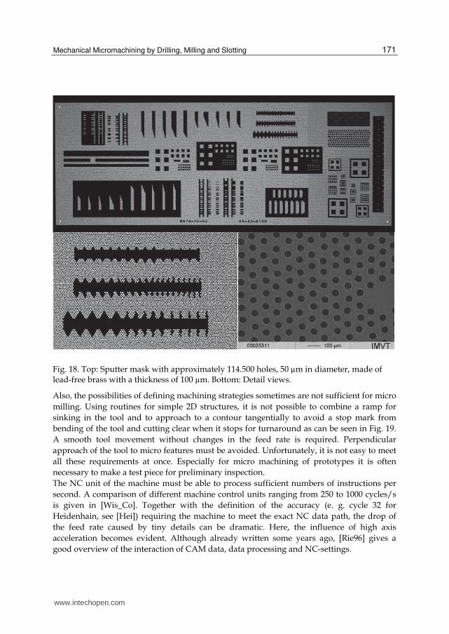
Fig. 18. Top: Sputter mask with approximately 114.500 holes, 50 µm in diameter, made of lead-free brass with a thickness of 100 µm. Bottom: Detail views.
Also, the possibilities of defining machining strategies sometimes are not sufficient for micro
milling. Using routines for simple 2D structures, it is not possible to combine a ramp for
sinking in the tool and to approach to a contour tangentially to avoid a stop mark from
bending of the tool and cutting clear when it stops for turnaround as can be seen in Fig. 19.
A smooth tool movement without changes in the feed rate is required. Perpendicular
approach of the tool to micro features must be avoided. Unfortunately, it is not easy to meet
all these requirements at once. Especially for micro machining of prototypes it is often
necessary to make a test piece for preliminary inspection.
The NC unit of the machine must be able to process sufficient numbers of instructions per
second. A comparison of different machine control units ranging from 250 to 1000 cycles/s
is given in [Wis_Co]. Together with the definition of the accuracy (e. g. cycle 32 for
Heidenhain, see [Hei]) requiring the machine to meet the exact NC data path, the drop of
the feed rate caused by tiny details can be dramatic. Here, the influence of high axis
acceleration becomes evident. Although already written some years ago, [Rie96] gives a
good overview of the interaction of CAM data, data processing and NC-settings.
www.intechopen.com
Micromachining Techniques for Fabrication of Micro and Nano Structures
172
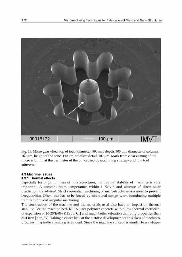
Fig. 19. Micro gearwheel top of teeth diameter: 800 µm, depth: 300 µm, diameter of column:
160 µm, height of the cone: 140 µm, smallest detail: 100 µm. Mark from clear cutting of the
micro end mill at the perimeter of the pin caused by machining strategy and low tool
stiffness.
4.3 Machine issues 4.3.1 Thermal effects Especially for large numbers of microstructures, the thermal stability of machines is very
important. A constant room temperature within 1 Kelvin and absence of direct solar
irradiation are advised. Strict sequential machining of microstructures is a must to prevent
irregularities. Often, this has to be forced by additional design work introducing multiple
frames to prevent irregular machining.
The construction of the machine and the materials used also have an impact on thermal
stability. For the machine bed, KERN uses polymer concrete with a low thermal coefficient
of expansion of 10-20*E-06/K [Epu_Cr] and much better vibration damping properties than
cast iron [Ker_Ev]. Taking a closer look at the historic development of this class of machines,
progress in spindle clamping is evident. Since the machine concept is similar to a c-shape-
www.intechopen.com

Mechanical Micromachining by Drilling, Milling and Slotting
173
rack and high-strength aluminium is used for the spindle clamping, the shape and fixing
position of the clamping to the machine have a high impact on thermal drift due to the high
thermal coefficient of expansion of 23*E-06/K of aluminum. For this reason, we changed the
original clamping of an older machine by one made of Invar (=1.7*E-06/K). Other
suppliers use granite and a portal architecture for their machines [Kug_Mg, Ltu] for low
thermal shift.
4.3.2 Clamping and measurement of micro end mills The detection of tool length and tool diameter by laser [Blu_Na] or mechanical dipping onto
a force sensor [Blu_Zp] is problematic for very small tool diameters. Laser measurement is
normally only possible above 100 µm tool diameter. According to [Blu_Ha], the limit was
recently shifted down to 10 µm diameter using special laser diodes. Mechanical dipping
ends at 50 µm tool diameter.
For such small tools, a very high true running accuracy is essential to make sure both cutting
edges are engaged at the same load. Collet chucks must be closed applying a certain torque.
Thermal shrinking is superior to mechanical clamping. True running accuracy for thermal
shrinkage [Die_Tg, Schun_Ce] or hydro stretch chucks [Schun_Tr] is about 3 µm, however,
collet chucks are in the range of 5 to 10 µm only [Far, Ntt_Er].
Finally, a number of interfaces from tool to the spindle are adding up. For minimization of
the run-out it is favourable to use vector-controlled spindles to ensure the same orientation
of the chuck inside the spindle.
4.3.3 Spindle speed Most machines on the market possess spindles with relatively low rotational speeds of 40-
60.000 rpm [Ker_Ev, Mak_22]. For micro machining, often very high numbers of revolution
are necessary to achieve reasonable material removal rates. However, much more
importance should be attached to questions like tool life, true running accuracy [Weu01,
Bis06], the stability and the dynamic behaviour of the machine.
The stability and damping behaviour of the machine are important to avoid vibrations and
chatter marks on the work piece surface as well as additional stress of the micro tool due to
vibrations. Often, polymer concrete with a very good damping behaviour superior to that of
grey cast iron is used for the machine base [Epu_Fi].
Especially for micro features, the dynamic behaviour, namely the acceleration of the axes,
the velocity to the NC-control unit and the maximum number of instructions per seconds
are important to maintain a programmed feed rate. In this context, also the definition of how
accurately the machine has to meet the calculated tool path is important. If the tolerance is
very low, the servo-loop can cause an extreme breakdown of the feed rate. This leads to
squeezing of the cutting edges, increased tool wear or even tool rupture. In the last decade,
the acceleration could be improved from about 1.2 m/s² to more than 2 g (20m/s²) [Wis_Ma]
also by using hydrostatic drives [Ker_Ac].
Especially high-frequency spindles lack sufficient torque at lower speed as well as an easy-
to-operate tool handling system. Mostly, three jaw chucks are used. Measurement of true
running accuracy is a must in this case for ensuring a constant engagement of the normally
two cutting edges of a micro end mill. Since the feed rate per tooth is far below 1 µm due to
machine limitations and since the true running accuracy and cutting edge rounding are not
www.intechopen.com
Micromachining Techniques for Fabrication of Micro and Nano Structures
174
taken into account, it is questionable if very high numbers of revolution in the range of
100.000 rpm and more that are stated e. g. in [Rus08] are appropriate. Instead, a minimal
feed per tooth is required to obtain chip formation at all [Duc09].
Often, machining parameters like rotational speed and feed rate cannot be extrapolated. For
instance, a speed of 15.000 rpm with a feed rate of 90 mm/min worked fine for micro
drilling using a 50 µm drill bit for the sputter mask displayed in Fig. 18 but 40.000 rpm and
240 mm/min did not.
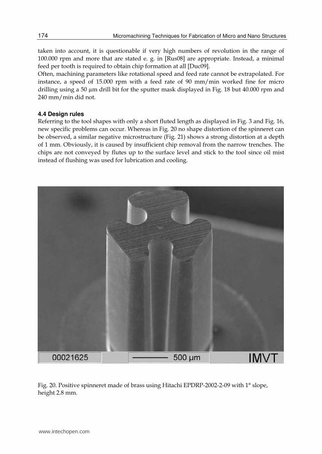
4.4 Design rules Referring to the tool shapes with only a short fluted length as displayed in Fig. 3 and Fig. 16,
new specific problems can occur. Whereas in Fig. 20 no shape distortion of the spinneret can
be observed, a similar negative microstructure (Fig. 21) shows a strong distortion at a depth
of 1 mm. Obviously, it is caused by insufficient chip removal from the narrow trenches. The
chips are not conveyed by flutes up to the surface level and stick to the tool since oil mist
instead of flushing was used for lubrication and cooling.
Fig. 20. Positive spinneret made of brass using Hitachi EPDRP-2002-2-09 with 1° slope, height 2.8 mm.
www.intechopen.com
Mechanical Micromachining by Drilling, Milling and Slotting
175
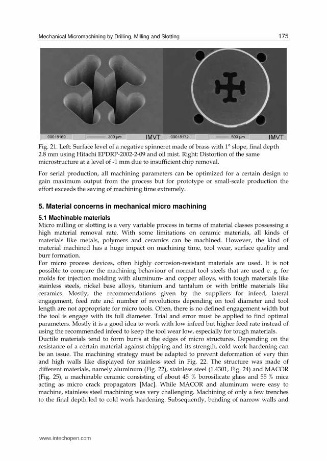
Fig. 21. Left: Surface level of a negative spinneret made of brass with 1° slope, final depth 2.8 mm using Hitachi EPDRP-2002-2-09 and oil mist. Right: Distortion of the same microstructure at a level of -1 mm due to insufficient chip removal.
For serial production, all machining parameters can be optimized for a certain design to
gain maximum output from the process but for prototype or small-scale production the
effort exceeds the saving of machining time extremely.
5. Material concerns in mechanical micro machining
5.1 Machinable materials Micro milling or slotting is a very variable process in terms of material classes possessing a high material removal rate. With some limitations on ceramic materials, all kinds of materials like metals, polymers and ceramics can be machined. However, the kind of material machined has a huge impact on machining time, tool wear, surface quality and burr formation. For micro process devices, often highly corrosion-resistant materials are used. It is not possible to compare the machining behaviour of normal tool steels that are used e. g. for molds for injection molding with aluminum- and copper alloys, with tough materials like stainless steels, nickel base alloys, titanium and tantalum or with brittle materials like ceramics. Mostly, the recommendations given by the suppliers for infeed, lateral engagement, feed rate and number of revolutions depending on tool diameter and tool length are not appropriate for micro tools. Often, there is no defined engagement width but the tool is engage with its full diameter. Trial and error must be applied to find optimal parameters. Mostly it is a good idea to work with low infeed but higher feed rate instead of using the recommended infeed to keep the tool wear low, especially for tough materials. Ductile materials tend to form burrs at the edges of micro structures. Depending on the resistance of a certain material against chipping and its strength, cold work hardening can be an issue. The machining strategy must be adapted to prevent deformation of very thin and high walls like displayed for stainless steel in Fig. 22. The structure was made of different materials, namely aluminum (Fig. 22), stainless steel (1.4301, Fig. 24) and MACOR (Fig. 25), a machinable ceramic consisting of about 45 % borosilicate glass and 55 % mica acting as micro crack propagators [Mac]. While MACOR and aluminum were easy to machine, stainless steel machining was very challenging. Machining of only a few trenches to the final depth led to cold work hardening. Subsequently, bending of narrow walls and
www.intechopen.com
Micromachining Techniques for Fabrication of Micro and Nano Structures
176
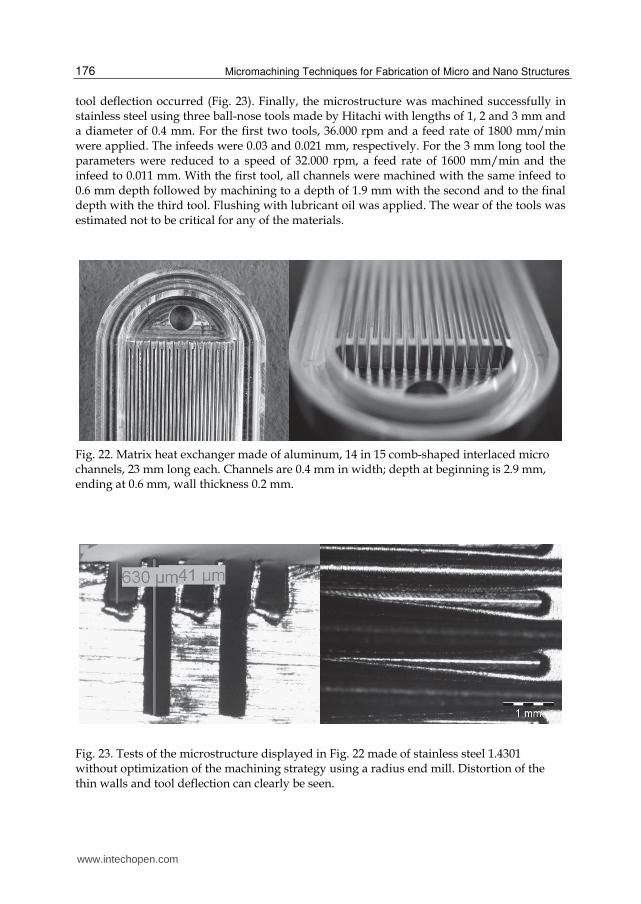
tool deflection occurred (Fig. 23). Finally, the microstructure was machined successfully in stainless steel using three ball-nose tools made by Hitachi with lengths of 1, 2 and 3 mm and a diameter of 0.4 mm. For the first two tools, 36.000 rpm and a feed rate of 1800 mm/min were applied. The infeeds were 0.03 and 0.021 mm, respectively. For the 3 mm long tool the parameters were reduced to a speed of 32.000 rpm, a feed rate of 1600 mm/min and the infeed to 0.011 mm. With the first tool, all channels were machined with the same infeed to 0.6 mm depth followed by machining to a depth of 1.9 mm with the second and to the final depth with the third tool. Flushing with lubricant oil was applied. The wear of the tools was estimated not to be critical for any of the materials.
Fig. 22. Matrix heat exchanger made of aluminum, 14 in 15 comb-shaped interlaced micro channels, 23 mm long each. Channels are 0.4 mm in width; depth at beginning is 2.9 mm, ending at 0.6 mm, wall thickness 0.2 mm.
Fig. 23. Tests of the microstructure displayed in Fig. 22 made of stainless steel 1.4301 without optimization of the machining strategy using a radius end mill. Distortion of the thin walls and tool deflection can clearly be seen.
www.intechopen.com
Mechanical Micromachining by Drilling, Milling and Slotting
177
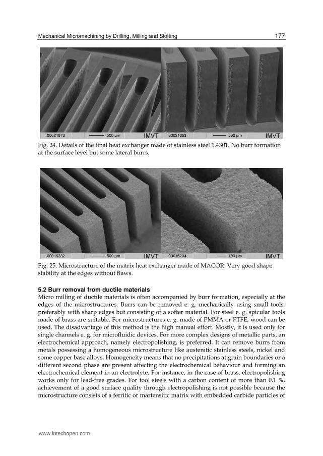
Fig. 24. Details of the final heat exchanger made of stainless steel 1.4301. No burr formation at the surface level but some lateral burrs.
Fig. 25. Microstructure of the matrix heat exchanger made of MACOR. Very good shape stability at the edges without flaws.
5.2 Burr removal from ductile materials Micro milling of ductile materials is often accompanied by burr formation, especially at the edges of the microstructures. Burrs can be removed e. g. mechanically using small tools, preferably with sharp edges but consisting of a softer material. For steel e. g. spicular tools made of brass are suitable. For microstructures e. g. made of PMMA or PTFE, wood can be used. The disadvantage of this method is the high manual effort. Mostly, it is used only for single channels e. g. for microfluidic devices. For more complex designs of metallic parts, an electrochemical approach, namely electropolishing, is preferred. It can remove burrs from metals possessing a homogeneous microstructure like austenitic stainless steels, nickel and some copper base alloys. Homogeneity means that no precipitations at grain boundaries or a different second phase are present affecting the electrochemical behaviour and forming an electrochemical element in an electrolyte. For instance, in the case of brass, electropolishing works only for lead-free grades. For tool steels with a carbon content of more than 0.1 %, achievement of a good surface quality through electropolishing is not possible because the microstructure consists of a ferritic or martensitic matrix with embedded carbide particles of
www.intechopen.com
Micromachining Techniques for Fabrication of Micro and Nano Structures
178
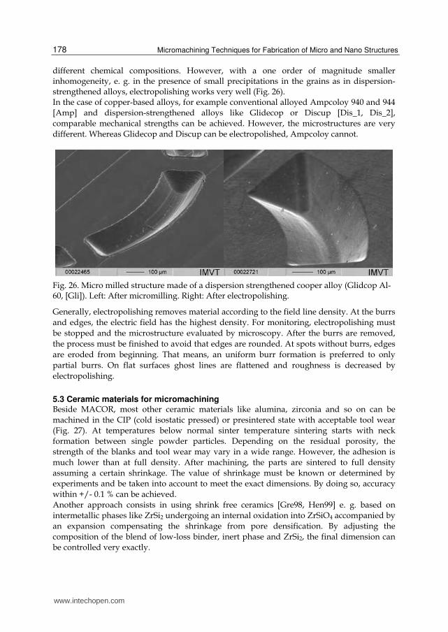
different chemical compositions. However, with a one order of magnitude smaller inhomogeneity, e. g. in the presence of small precipitations in the grains as in dispersion-strengthened alloys, electropolishing works very well (Fig. 26). In the case of copper-based alloys, for example conventional alloyed Ampcoloy 940 and 944
[Amp] and dispersion-strengthened alloys like Glidecop or Discup [Dis_1, Dis_2],
comparable mechanical strengths can be achieved. However, the microstructures are very
different. Whereas Glidecop and Discup can be electropolished, Ampcoloy cannot.
Fig. 26. Micro milled structure made of a dispersion strengthened cooper alloy (Glidcop Al-60, [Gli]). Left: After micromilling. Right: After electropolishing.
Generally, electropolishing removes material according to the field line density. At the burrs
and edges, the electric field has the highest density. For monitoring, electropolishing must
be stopped and the microstructure evaluated by microscopy. After the burrs are removed,
the process must be finished to avoid that edges are rounded. At spots without burrs, edges
are eroded from beginning. That means, an uniform burr formation is preferred to only
partial burrs. On flat surfaces ghost lines are flattened and roughness is decreased by
electropolishing.
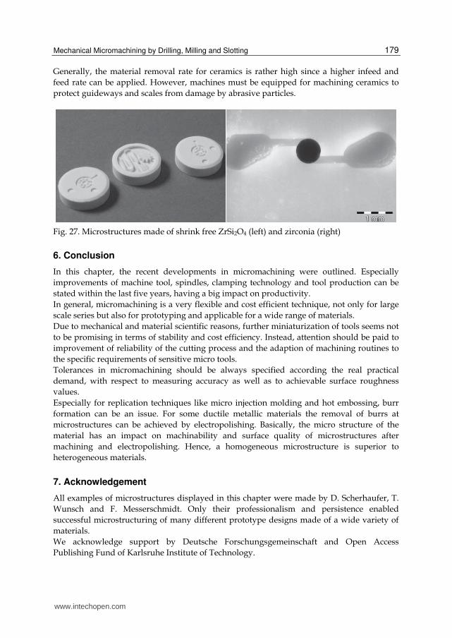
5.3 Ceramic materials for micromachining Beside MACOR, most other ceramic materials like alumina, zirconia and so on can be
machined in the CIP (cold isostatic pressed) or presintered state with acceptable tool wear
(Fig. 27). At temperatures below normal sinter temperature sintering starts with neck
formation between single powder particles. Depending on the residual porosity, the
strength of the blanks and tool wear may vary in a wide range. However, the adhesion is
much lower than at full density. After machining, the parts are sintered to full density
assuming a certain shrinkage. The value of shrinkage must be known or determined by
experiments and be taken into account to meet the exact dimensions. By doing so, accuracy
within +/- 0.1 % can be achieved.
Another approach consists in using shrink free ceramics [Gre98, Hen99] e. g. based on
intermetallic phases like ZrSi2 undergoing an internal oxidation into ZrSiO4 accompanied by
an expansion compensating the shrinkage from pore densification. By adjusting the
composition of the blend of low-loss binder, inert phase and ZrSi2, the final dimension can
be controlled very exactly.
www.intechopen.com
Mechanical Micromachining by Drilling, Milling and Slotting
179
Generally, the material removal rate for ceramics is rather high since a higher infeed and
feed rate can be applied. However, machines must be equipped for machining ceramics to
protect guideways and scales from damage by abrasive particles.
Fig. 27. Microstructures made of shrink free ZrSi2O4 (left) and zirconia (right)
6. Conclusion
In this chapter, the recent developments in micromachining were outlined. Especially
improvements of machine tool, spindles, clamping technology and tool production can be
stated within the last five years, having a big impact on productivity.
In general, micromachining is a very flexible and cost efficient technique, not only for large
scale series but also for prototyping and applicable for a wide range of materials.
Due to mechanical and material scientific reasons, further miniaturization of tools seems not
to be promising in terms of stability and cost efficiency. Instead, attention should be paid to
improvement of reliability of the cutting process and the adaption of machining routines to
the specific requirements of sensitive micro tools.
Tolerances in micromachining should be always specified according the real practical
demand, with respect to measuring accuracy as well as to achievable surface roughness
values.
Especially for replication techniques like micro injection molding and hot embossing, burr
formation can be an issue. For some ductile metallic materials the removal of burrs at
microstructures can be achieved by electropolishing. Basically, the micro structure of the
material has an impact on machinability and surface quality of microstructures after
machining and electropolishing. Hence, a homogeneous microstructure is superior to
heterogeneous materials.
7. Acknowledgement
All examples of microstructures displayed in this chapter were made by D. Scherhaufer, T.
Wunsch and F. Messerschmidt. Only their professionalism and persistence enabled
successful microstructuring of many different prototype designs made of a wide variety of
materials.
We acknowledge support by Deutsche Forschungsgemeinschaft and Open Access
Publishing Fund of Karlsruhe Institute of Technology.
www.intechopen.com
Micromachining Techniques for Fabrication of Micro and Nano Structures
180
8. References
Amp, data sheets of different Amcoloy-alloys, date of access: 16.08.2011, available from: http://www.ampcometal.com/common/datasheets/ampco_alloy_brochure.pdf
Ato_Ad, Atom Saito Seisakusho micro drill bit ADR-0002, date of access: 16.08.2011, available from:
http://www.atom21.co.jp/english/detail.php?act=view&page=0&id= adr&u=mm Bis06, G. Bissacco, H. N. Hansen, L. De Chiffre: “Size Effects on Surface Generation in Micro
Milling of Hardened Tool Steel”, CIRP Annals - Manufacturing Technology, vol. 55, Issue 1, pp. 593-596, 2006
Blu_Ha L. Halder, answer be email from 13/07/2011: tools down to 10 µm in diameter with special laser diode detectable
Blu_Na, Blum LaserControl Nano NT, date of access: 16.08.2011, available from: http://www.blum-novotest.de/de/messkomponenten/produkte/optische-werkzeugmessung/lasercontrol-nt.html
Blu_Zp, Blum Probe Z-Pico, date of access: 16.08.2011, available from: http://www.blum-novotest.de/uploads/media/Z-Pico_EN.pdf Bor04, S. Borek, K. Schauer, M. Füting, A. Heilmann: „Endbearbeitung von Mikrofräsern
mittels Ionenstrahltechniken“, wt Werkstattechnik online, vol. 94, no. 11/12, pp. 600-604, 2004
Con, Contour, Fine Tooling Ltd., Wedgwood Way, Stevenage, Herts SG1 4QR, UK, date of access: 26.09.2011, available from:
http://www.contour-diamonds.com/HTML/ mircromilling.html Die_Tg, Diebold ThermoGrip, p. 6, date of access: 16.08.2011, available from: http://www.diebold-hsk.de/pdfs/04.pdf Dis_1, presentation dispersion-strengthened Discup-alloy, date of access: 26.09.2011,
available from: http://www.kupfer-institut.de/symposium/media/pdf/Cu-Werkstoffe durch
PM.pdf Dis_2, information about Discup can be ordered under: http://www.ecka-granules.com/en/ecka-granules/products/catalogue-request/ Duc09, F. Ducobu, E. Filippi, E. Rivière-Lorphèvre: “Chip Formation and Minimum Chip
Thickness in Micro-milling”, Proc. of the 12th CIRP Conference on Modeling of Machining Operations, pp 339-346, 2009
Epu_Cr, overview about different types of polymer concrete possessing different thermal coefficients of expansion, date of access: 15.09.2011, available from:
http://www.epucret.de/en/epument-machine-beds-made-of-mineral-casting/ materials/
Epu_Fi, Epufill – Composite structures with mineral casting filling, p. 3, date of access: 16.08.2011, available from:
http://www.epucret.de/fileadmin/rampf_downloadcenter/EPUCRET-Mineralgusstechnik/Broschueren/EPUFILL/EPU_ Epufill_GB.pdf
Ewa_Ws, Ewag AG, Industriestr. 4, 4554 Etziken, Switzerland, date of access: 26.09.2011, product information availabe from:
http://www.ewag.com/de/produkte/ schleifen/ws-11.html Exn70, H. E. Exner, J. A Gurland: ”A review of parameters influencing some mechanical
properties of tungsten carbide cobalt alloy”, Powder Metallurgy, vol. 13, pp. 13-31, 1970
Far, Farion collet chucks, date of access: 26.09.2011, available from:
www.intechopen.com
Mechanical Micromachining by Drilling, Milling and Slotting
181
http://shop.fahrion.de/index.php?id=17&mastersku=HF-A8+f%C3%BCr+CP& pgsn=060280030&sdzgrouping=FAHRION+450E+FM32&L=0&chash=cdf728&&L=1
Fri08, A. H. Fritz, G. Schulze: “Fertigungstechnik“, 8th ed., Springer, p. 264, 2008 Gli, data sheet of dispersion strengthened Cu-alloy Glidecop Al-60, date of access:
26.09.2011, available from: http://www.spotweldingconsultants.com/GlidCop_AL_60.pdf Gre98, P. Greil: „Near Net Shape Manufacturing of Polymer Derived Ceramics”, J. of. Europ.
Ceram. Soc., vol. 18, pp. 1905-1914, 1998 Ham_38, Hartmetall-Werkzeugfabrik Andreas Maier GmbH, 88477 Schwendi-Hörenhausen,
series HAM 382 Micro Prima, date of access: 26.09.2011, product information available from:
http://www.ham-tools.com/fileadmin/templates_ham/ Download/HAM_Micro.pdf, oral information and already bought: diameter 30 µm
Hei, technical info, permissible contour deviation, p. 3, date of access: 16.08.2011, available from:
http://www.heidenhain.de/fileadmin/pdb/media/img/636_225-21.pdf Hen99 V. D. Hennige et al.: “Shrink-free ZrSiO4-ceramics: Characterisation and
Applications”, J. of. Europ. Ceram. Soc., vol. 19, pp. 2901-2908, 1999 Hte_Em, Hitachi Tool Engineering Europe GmbH, Itterpark 12, 40724 Hilden, series EMM,
date of access: 26.02.2011, product information available from: http://www. hitachitool-eu.com/download/brochures/view/emm.pdf Hte_Ep1, Brochure 413, EPDBP/EPDRP, Hitachi Tool Engineering Europe GmbH, Itterpark
12, 40724 Hilden, Germany, 2005, date of access: 26.09.2011, available from: http://www.hitachimetals.com/product/cuttingtools/pdf_solid/epdb_epdbp_lo
w_res.pdf Hte_Ep2, Coated 100 µm-end mills, AR=10 by Hitachi Tool Engineering Europe GmbH,
series EPDS, date of access: 16.08.2011, date of access: 16.08.2011, product information available from:
http://www.hitachitool-eu.com/download/ brochures/view/epds.pdf Ker_Ac, acceleration of KERN-machines, date of access: 15.09.2011, available from: http://www.kern-microtechnic.com/page.php?page_id=53&lid=1 Ker_Ev, Usage of polymer concrete and spindles by KERN Micro- und Feinwerktechnik,
date of access: 26.09.201, available from: http://www.kern-microtechnic.com/ upload/media/kern_evo_e.pdf Klo05, F. Klocke, J. v. Bodenhausen, K. Arntz: „Prozesssicherheit bei der
Mikrofräsbearbeitung“, wt Werkstattstechnik online, issue 95, vol. 11-12, pp. 882-886, 2005
Kön90, W. König: „Fertigungsverfahren –Drehen, Bohren, Fräsen-“, vol. 1, 3rd ed., VDI-publishing, ISBN 3-18-400843-6, p.63, 1990
Kön99, W. König: „Fertigungsverfahren –Schleifen, Honen, Läppen-“, vol. 2, 2nd ed., VDI-publishing, ISBN 3-18-400180-X, p.11, 1990
Kug_Mg, Kugler, MICROGANTRY nano 3/5X, date of access: 26.09.2011, available from: http://www.kugler-precision.com/index.php?page=99&modaction=detail
&modid=188 Ltu, LT-Ultra, UP-Machine, MSC-1100, date of access: 26.09.2011, available from: http://www.lt-ultra.com/index.php/de/up-maschine/msc-1100 Mac, MACOR, machinable glassy ceramic, date of access: 26.09.2011, available from:
http://www.precision-ceramics.co.uk/mcomp.htm
www.intechopen.com
Micromachining Techniques for Fabrication of Micro and Nano Structures
182
Mak_22, spindle speed of Makino V22, date of access: 15.09.2011, available from: http://www.makino.com/machines/V22/Graphite/
Med, Medidia GmbH, Alte Poststr. 23, 55743 Idar-Oberstein, date of access: 26.09.2011, available from:
http://www.medidia-diamond-tools.com/page/?menu=220 Möß, Mößner GmbH, Kelterstr. 82, 75179 Pforzheim, date of access: 16.08.2011, available
from: http://www.hamoedia.de/html/m-k-d-wz.html Nst_Di, Monocrystalline diamond end mills by NS Tool Co. Ltd., Japan, date of access:
26.09.2011, available from: http://www.ns-tool.com/cgi-bin/e/docat/dt.php?j =1&s=73 Nst_Em, Coated 100 µm-end mills, AR=10 NS Tool Co. Ltd., Japan, date of access:
26.09.2011, available from: http://www.ns-tool.com/cgi-bin/e/docat/dt.php?j=1&s=9 Ntt_Er, ERC precision collet chuck, date of access: 15.09.2011, available from:
http://www.nttooleurope.com/products/erc/ Rie96, Asko Riehn: “The Challenges of High Speed Cutting”, published in “Modern Machine
Shop”, May 1996, date of access: 15.09.2011, available from: http://findarticles.com /p/articles/mi_m3101/is_n12_v68/ai_18389412/ Rus08, Rusnaldy, T. J. Ko, H. S. Kim: „An experimental study on microcutting of silicon
using a micromilling machine”, Int. J. Adv. Manuf. Technol., vol. 39, pp. 85-91, 2008 Sad99, R. K. Sadangi et al.: ”Grain growth inhibition in Liquid Phase Sintered of Nanophase
WC/Co Alloys”, Int. J. of powder metallurgy, No. 35, vol. 1, pp. 27-33, 1999 Schun_Ce, Schunk, CELSIO SSF HSK-A 32, p. 78, date of access: 16.08.2011, available from:
http://www.schunk.com/schunk_files/attachments/WZH-Systeme__HSK__DE_EN.pdf
Schun_Tr, Schunk, HSK-E 25 Tribos Polygonal Toolholder, p. 130, date of access: 16.08.2011, available from: http://www.schunk.com/schunk_files/attachments/TRIBOS-RM_Aufnahmeschaft_HSK-E_DE_EN.pdf
Uhl06, E. Uhlmann, D. Oberschmidt, K. Schauer: „Innovative Fräswerkzeuge für die Mikrozerspanung“, wt Werkstattstechnik online, issue 96, vol. 1-2, pp. 2-5, 2006
Upa98, G. S. Upadhyaya: „Cemented Tungsten Carbides – Production Properties and Testing“, Noyes Publications, U.S., ISBN 0-8155-1417-4, p. 25, 1998
War00, G. Warnecke, K. Eichgrün, L. Schäfer: „Zuverlässige Serienbauteile aus Hochleistungskeramik“, Ingenieur-Werkstoffe, Nr. 2, April 2000
Wei96, F. Weiland: „Cerametal S.à.r.l., eine Spitzenadresse nicht nur in Europa. Hartmetall und Hartmetallwerkzeuge auf und mit Welt-Niveau“ Revue Technique Luxembourgeoise, vol. 2, 1996
Wer, Werth fiber probe, date of access: 26.09.2011, available from: http://www.werth.de/ index.php?id=76&L=1 Weu01, H. Weule, V. Hüntrup, H. Tritschler: „Micro-Cutting of Steel to Meet New
Requirements in Miniaturization”, CIRP Annals - Manufacturing Technology, vol. 50, Issue 1, pp. 61-64, 2001
Wis_Co, Comparison of the velocity of different NC`s, date of access: 26.09.2011, available from: http://www.wissner-gmbh.de/Page/Technologie/ steuerungen.htm
Wis_Ma, acceleration of WISSNER-machines, date of access: 26.09.2011, available from: http://www.wissner-gmbh.de/Page/GAMMA/gamma303.htm
Yao_Wc, Z. Yao, J. J. Stiglich, T. S. Sudarshan: „Nanograined Tungsten Carbide-Cobalt (WC/Co)“, p. 8, date of access: 26.09.2011, available from:
http://www.matmod. com/Publications/armor_1.pdf
www.intechopen.com
Micromachining Techniques for Fabrication of Micro and NanoStructuresEdited by Dr. Mojtaba Kahrizi
ISBN 978-953-307-906-6Hard cover, 300 pagesPublisher InTechPublished online 03, February, 2012Published in print edition February, 2012
InTech EuropeUniversity Campus STeP Ri Slavka Krautzeka 83/A 51000 Rijeka, Croatia Phone: +385 (51) 770 447 Fax: +385 (51) 686 166www.intechopen.com
InTech ChinaUnit 405, Office Block, Hotel Equatorial Shanghai No.65, Yan An Road (West), Shanghai, 200040, China
Phone: +86-21-62489820 Fax: +86-21-62489821
Micromachining is used to fabricate three-dimensional microstructures and it is the foundation of a technologycalled Micro-Electro-Mechanical-Systems (MEMS). Bulk micromachining and surface micromachining are twomajor categories (among others) in this field. This book presents advances in micromachining technology. Forthis, we have gathered review articles related to various techniques and methods of micro/nano fabrications,like focused ion beams, laser ablation, and several other specialized techniques, from esteemed researchersand scientists around the world. Each chapter gives a complete description of a specific micromachiningmethod, design, associate analytical works, experimental set-up, and the final fabricated devices, followed bymany references related to this field of research available in other literature. Due to the multidisciplinary natureof this technology, the collection of articles presented here can be used by scientists and researchers in thedisciplines of engineering, materials sciences, physics, and chemistry.
How to referenceIn order to correctly reference this scholarly work, feel free to copy and paste the following:
T. Gietzelt and L. Eichhorn (2012). Mechanical Micromachining by Drilling, Milling and Slotting, MicromachiningTechniques for Fabrication of Micro and Nano Structures, Dr. Mojtaba Kahrizi (Ed.), ISBN: 978-953-307-906-6,InTech, Available from: http://www.intechopen.com/books/micromachining-techniques-for-fabrication-of-micro-and-nano-structures/mechanical-micromachining-by-drilling-milling-and-slotting

© 2012 The Author(s). Licensee IntechOpen. This is an open access articledistributed under the terms of the Creative Commons Attribution 3.0License, which permits unrestricted use, distribution, and reproduction inany medium, provided the original work is properly cited.