MEP201 Mechanical Engineering Drawing 1 st semester 2005-2006
Mechanical Engineering Drawing (ME 1200)
Dr. Md. Shahidul Islam
Assistant Professor
Department of Mechanical Engineering
Khulna University of Engineering & Technology
Mechanical Engineering Drawing
Syllabus:
Fundamental principles and applications of Orthogonal projection; Visibility, Angle problem; Oblique projection; Isometric projection; Auxiliary projection, Orthographic and auxiliary projection from pictorial views; pictorial projection from orthographic views, Development of objects.
Descriptive Geometry: Projection, methods of transferring projection, practical application of descriptive geometry.
Reference Books:
1. Technical Drawing – Frederick E. Giesecke, Alva Mitchell, Henry Cecil Spencer, Ivan Leroy Hill and John Thomas Dygdon.
2. Fundamental of Engineering Drawing – Warren J. Luzaddder and Jon M. Duff.
Drawing:
A drawing is a graphic representation of a real thing, an idea or a proposed design for construction later. Drawing may take many forms, but the graphic method of representation is a basic natural form of communication of ideas that is universal and timeless in character.
Types of Drawing:
Man has developed graphic representation along two distinct lines, according to his purpose: (i) Artistic and (ii) Technical.
From the beginning of time, artists have used drawing to express aesthetic, philosophic or other abstract ideas. I ancient times nearly everybody was illiterate. There was no printing and hence no newspaper or books. People learned by listening to their superiors and by looking at pictures, or drawing in public places. Everybody could understand picture and they were a principle source of information.
The other line along which drawing has developed has been the technical. From the beginning of recorded history, man has used drawing to represent his design of objects to be built or constructed.
Instruments:
A complete list of equipments, which should provide a satisfactory selection for students of technical drawing is as follows:
Page 1 of 17
(1) Drawing board (Approximate 20”×20”), drafting table or desk.
(2) T-square (24”, transparent edge)
(3) Set of instruments
(4) 45º triangle (8” side)
(5) 30º ×60º triangle (10” long side)
(6) Irregular curve
(7) Pencils (2B, HB, 3H)
(8) Protractor
(9) Eraser
(10) Dusting brush
(11) Drafting tape
(12) Circle and ellipse templates.
READING DRAWINGS
To read a drawing, you must know how engineers use lines, dimensions, and notes to communicate their ideas on paper. In this section, we briefly discuss each of these drawing elements.
Lines
Figure 3-38 shows many of the different types of lines that are used in drawings. You can see that each line has a specific meaning you must understand to interpret a drawing correctly. Let’s discuss a few of the most important types. A visible line (sometimes called object line) is used to show the edges of an object that are visible to the viewer. For example, if you look at one of the walls of the room you are in, you can see the outline of the walls and (depending on the wall you are looking at) the outline of doors and windows. On a drawing, these visible outlines or edges can be shown using visible lines that are drawn as described in figure 3-38.
Now look at the wall again. Assuming that the wall is wood frame, you know that there are studs or framing members inside the wall that you cannot see. Also, the wall may contain other items, such as water pipes and electrical conduit, that you also cannot see. On a drawing, the edges of those concealed studs and other items can be shown using hidden lines (fig.3-38). These lines are commonly used in drawings. As you can imagine, the more hidden lines there are, the more difficult it becomes to decipher what is what; however, there is another way these studs and other items can be “seen.” Imagine that you “cut away” the wallboard that covers the wall and replace it with a sheet of clear plastic. That clear plastic can be thought of as a cutting or viewing plane (fig.3-38) through which the previously concealed studs, piping, and conduit are now visible. Now those items can be drawn using visible lines, rather than hidden lines. A view of this type is called a sectional view, and a drawing of the view is called a section drawing. Section drawings are commonly used to show the internal components of a complicated object.
Page 2 of 17
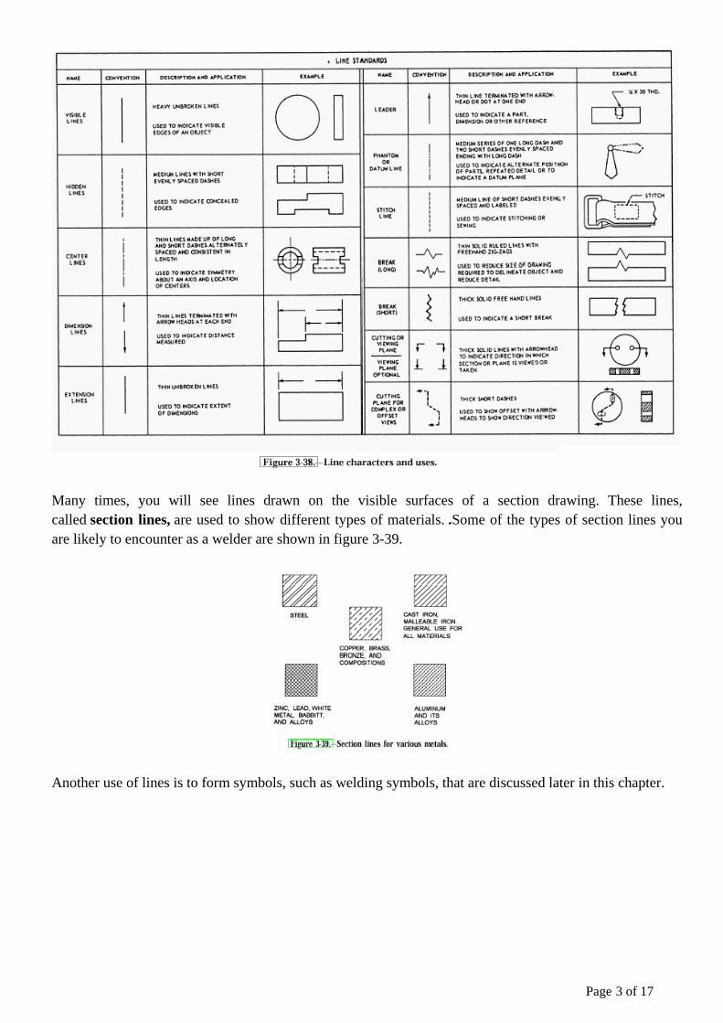
Many times, you will see lines drawn on the visible surfaces of a section drawing. These lines, called section lines, are used to show different types of materials. .Some of the types of section lines you are likely to encounter as a welder are shown in figure 3-39.
Another use of lines is to form symbols, such as welding symbols, that are discussed later in this chapter.
Page 3 of 17
Dimensions
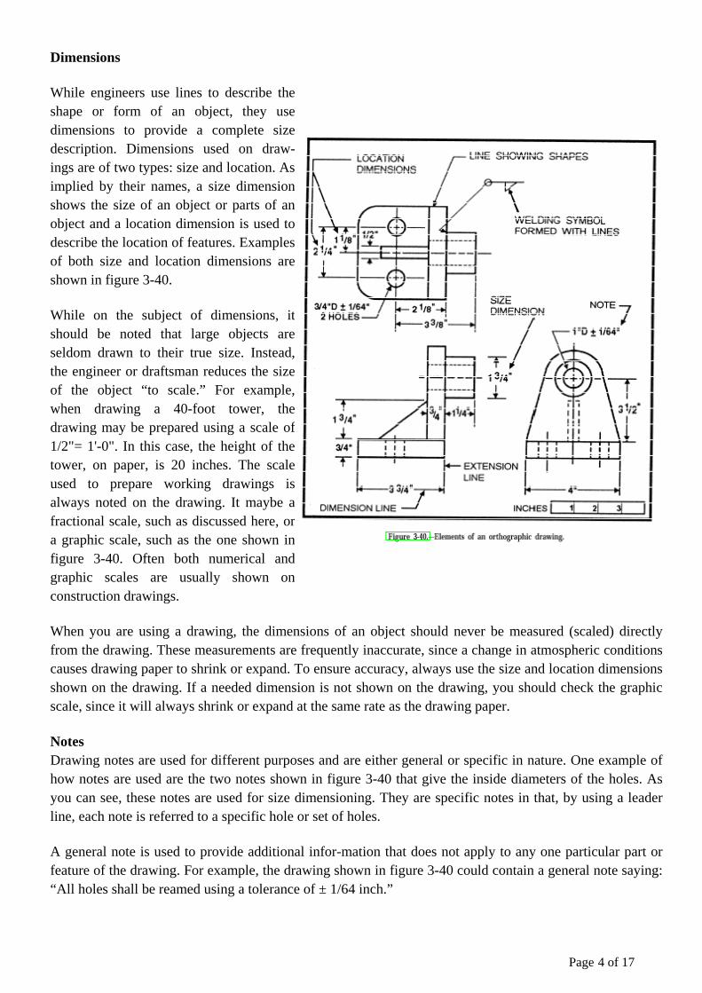
While engineers use lines to describe the shape or form of an object, they use dimensions to provide a complete size description. Dimensions used on draw-ings are of two types: size and location. As implied by their names, a size dimension shows the size of an object or parts of an object and a location dimension is used to describe the location of features. Examples of both size and location dimensions are shown in figure 3-40.
While on the subject of dimensions, it should be noted that large objects are seldom drawn to their true size. Instead, the engineer or draftsman reduces the size of the object “to scale.” For example, when drawing a 40-foot tower, the drawing may be prepared using a scale of 1/2"= 1'-0". In this case, the height of the tower, on paper, is 20 inches. The scale used to prepare working drawings is always noted on the drawing. It maybe a fractional scale, such as discussed here, or a graphic scale, such as the one shown in figure 3-40. Often both numerical and graphic scales are usually shown on construction drawings.
When you are using a drawing, the dimensions of an object should never be measured (scaled) directly from the drawing. These measurements are frequently inaccurate, since a change in atmospheric conditions causes drawing paper to shrink or expand. To ensure accuracy, always use the size and location dimensions shown on the drawing. If a needed dimension is not shown on the drawing, you should check the graphic scale, since it will always shrink or expand at the same rate as the drawing paper.
Notes Drawing notes are used for different purposes and are either general or specific in nature. One example of how notes are used are the two notes shown in figure 3-40 that give the inside diameters of the holes. As you can see, these notes are used for size dimensioning. They are specific notes in that, by using a leader line, each note is referred to a specific hole or set of holes.
A general note is used to provide additional infor-mation that does not apply to any one particular part or feature of the drawing. For example, the drawing shown in figure 3-40 could contain a general note saying: “All holes shall be reamed using a tolerance of ± 1/64 inch.”
Page 4 of 17

Drawing Views
Look at the drawing shown in figure 3-41. This type of drawing is called a pictorial drawing. These draw-ings are frequently used to show how an object should appear after it is manufactured. Pictorial drawings are used as working drawings for a simple item, such as a metal washer. For a more complex object, as shown in figure 3-41, it becomes too difficult to provide a com-plete description in a pictorial drawing. In this case, it is common practice to prepare orthographic drawings to describe the object fully.
Assume you are holding the object shown in figure 3-41 in your hands. When you hold the object so you are looking directly at the top face of the object, the view you see is the top view. A drawing of that view is called an orthographic drawing.
Obviously, an orthographic drawing of only the top view of the object is insufficient to describe the entire object; therefore, additional orthographic drawings of one or more of the other faces of the object are necessary. The number of orthographic views needed to describe an object fully depends upon the complexity of the object. For example, a simple metal washer can be fully described using only one orthographic view; however, an extremely complex object may require as many as six views (top, front, left side, right side, back, and bottom). Most objects, such as the steel part shown in figure 3-41, can be sufficiently described using three views: top, front, and right side. For the object shown in figure 3-41, orthographic drawings of the top, front, and right-side views are shown in figure 3-42.
Notice the placement of the views shown in figure 3-42. This is a standard practice that you should be aware of when reading orthographic drawings. By this standard practice, the top view is always placed above the front view and the right-side view is placed to the right of the front view. When additional views are needed, the left side is always drawn to the left of the front view and the bottom is drawn below the front view. Placement of the back view is somewhat flexible; how-ever, it is usually drawn to the left of the left-side view. When reading and understanding the different orthographic views, you find it is sometimes helpful to prepare a pictorial sketch.
Think of drawings as a form of communication. They are intended to help you understand all the necessary information you need to fabricate and assemble an object regardless of the complexity. It is important that you learn to read drawings.
Handling and Care of Drawings Special care should be exercised in the handling of drawings. When they are not being used, keep them on a rack or in another assigned place of storage. Drawings are valuable, and they may be difficult or impossible to replace if they are lost or damaged.
Page 5 of 17
Types of Lines
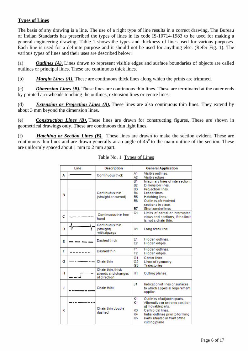
The basis of any drawing is a line. The use of a right type of line results in a correct drawing. The Bureau of Indian Standards has prescribed the types of lines in its code IS-10714-1983 to be used for making a general engineering drawing. Table 1 shows the types and thickness of lines used for various purposes. Each line is used for a definite purpose and it should not be used for anything else. (Refer Fig. 1). The various types of lines and their uses are described below:
(a) Outlines (A). Lines drawn to represent visible edges and surface boundaries of objects are called outlines or principal lines. These are continuous thick lines.
(b) Margin Lines (A). These are continuous thick lines along which the prints are trimmed.
(c) Dimension Lines (B). These lines are continuous thin lines. These are terminated at the outer ends by pointed arrowheads touching the outlines, extension lines or centre lines.
(d) Extension or Projection Lines (B). These lines are also continuous thin lines. They extend by about 3 mm beyond the dimension lines.
(e) Construction Lines (B). These lines are drawn for constructing figures. These are shown in geometrical drawings only. These are continuous thin light lines.
(f) Hatching or Section Lines (B). These lines are drawn to make the section evident. These are continuous thin lines and are drawn generally at an angle of 450 to the main outline of the section. These are uniformly spaced about 1 mm to 2 mm apart.
Table No. 1 Types of Lines
Page 6 of 17
(g) Leader or Pointer Lines (B). Leader line is drawn to connect a note with the feature to which it applies. It is a continuous thin line.
(h) Border Lines (B). Perfectly rectangular working space is determined by drawing the border lines. These are continuous thin lines.
(j) Short-Break Lines (C). These lines are continuous, thin and wavy. These are drawn freehand and are used to show a short break, or irregular boundaries.
(k) Long-Break Lines (D). These lines are thin ruled lines with short zigzags within them. These are drawn to show long breaks.
(l) Hidden or Dotted Lines (E or F). Interior or hidden edges and surfaces are shown by hidden lines. These are also called dashed lines or dotted lines. These are of medium thickness and made up of short dashes of approximately equal lengths of about 2 mm spaced at equal distances of about 1 mm. When a hidden line meets or intersects another hidden line or an outline, their point of intersection or meeting should be clearly shown.
(m) Centre Lines (G). Centre lines are drawn to indicate the axes of cylindrical, conical or spherical objects or details, and also to show the centers of circles and arcs. These are thin, long, chain lines composed of alternately long and short dashes spaced approximately 1 mm apart. The longer dashes are about 6 to 8 times the short dashes which are about 1.5 mm long. Centre lines should extend for a short distance beyond the outlines to which these refer. For the purpose of dimensioning or to correlate the views these may be extended as required. The point of intersection between two centre lines must always be indicated. Locus lines, extreme positions of movable parts and pitch circles are also shown by this type of line.
(n) Cutting-Plane Lines (H). The location of a cutting plane is shown by this line. It is a long, thin chain line, thick at ends only.
(o) Chain Thick (J). These lines are used to indicate special treatment on the surface.
(p) Chain Thick Double Dashed (K). This chain thin double dashed is used for outline for adjacent parts, alternative and extreme, position of movable part, centroidal lines, initial outlines prior to forming and part suited in front of the cutting plane.
Page 7 of 17
Introduction
One of the best ways to communicate one's ideas is through some form of picture or drawing. This is especially true for the engineer. The purpose of this guide is to give you the basics of engineering sketching and drawing.
We will treat "sketching" and "drawing" as one. "Sketching" generally means freehand drawing. "Drawing" usually means using drawing instruments, from compasses to computers to bring precision to the drawings.
This is just an introduction. Don't worry about understanding every detail right now - just get a general feel for the language of graphics.
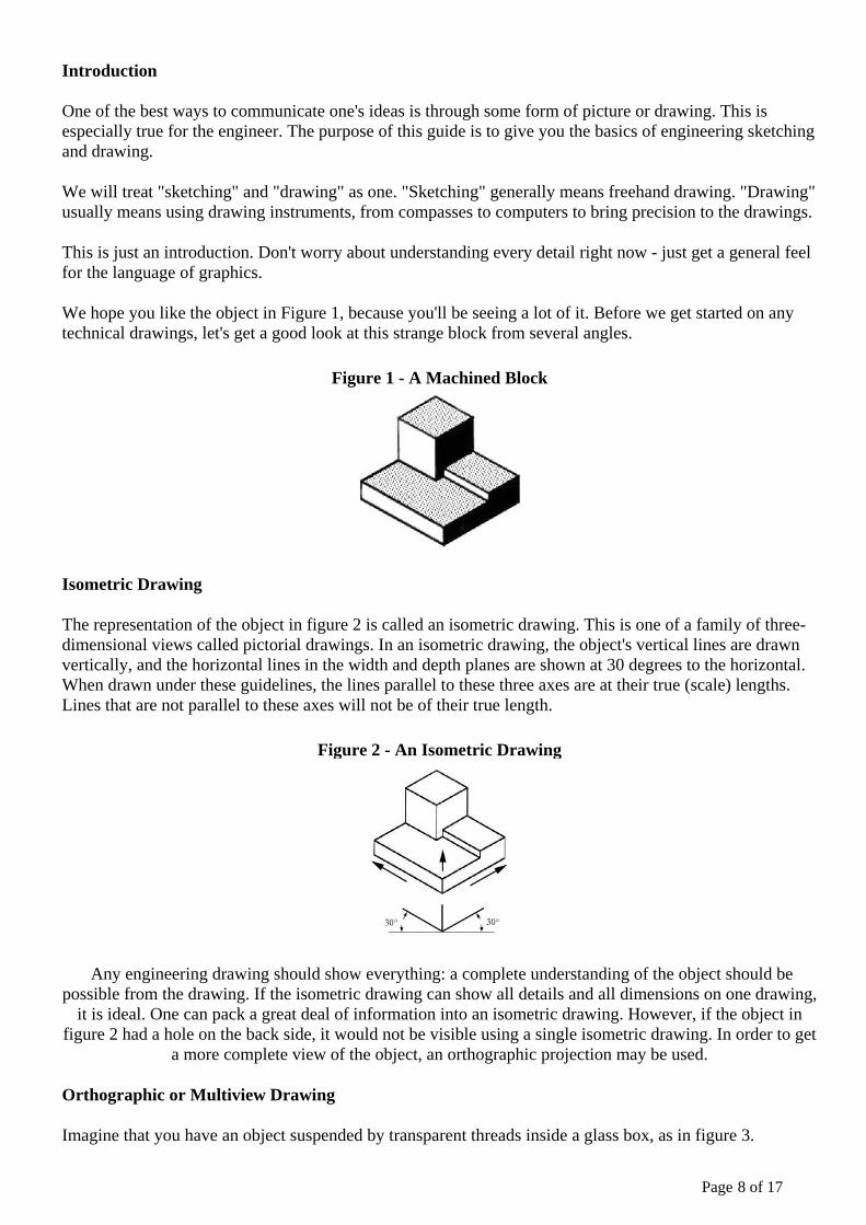
We hope you like the object in Figure 1, because you'll be seeing a lot of it. Before we get started on any technical drawings, let's get a good look at this strange block from several angles.
Figure 1 - A Machined Block
Isometric Drawing
The representation of the object in figure 2 is called an isometric drawing. This is one of a family of three-dimensional views called pictorial drawings. In an isometric drawing, the object's vertical lines are drawn vertically, and the horizontal lines in the width and depth planes are shown at 30 degrees to the horizontal. When drawn under these guidelines, the lines parallel to these three axes are at their true (scale) lengths. Lines that are not parallel to these axes will not be of their true length.
Figure 2 - An Isometric Drawing
Any engineering drawing should show everything: a complete understanding of the object should be possible from the drawing. If the isometric drawing can show all details and all dimensions on one drawing,
it is ideal. One can pack a great deal of information into an isometric drawing. However, if the object in figure 2 had a hole on the back side, it would not be visible using a single isometric drawing. In order to get
a more complete view of the object, an orthographic projection may be used.
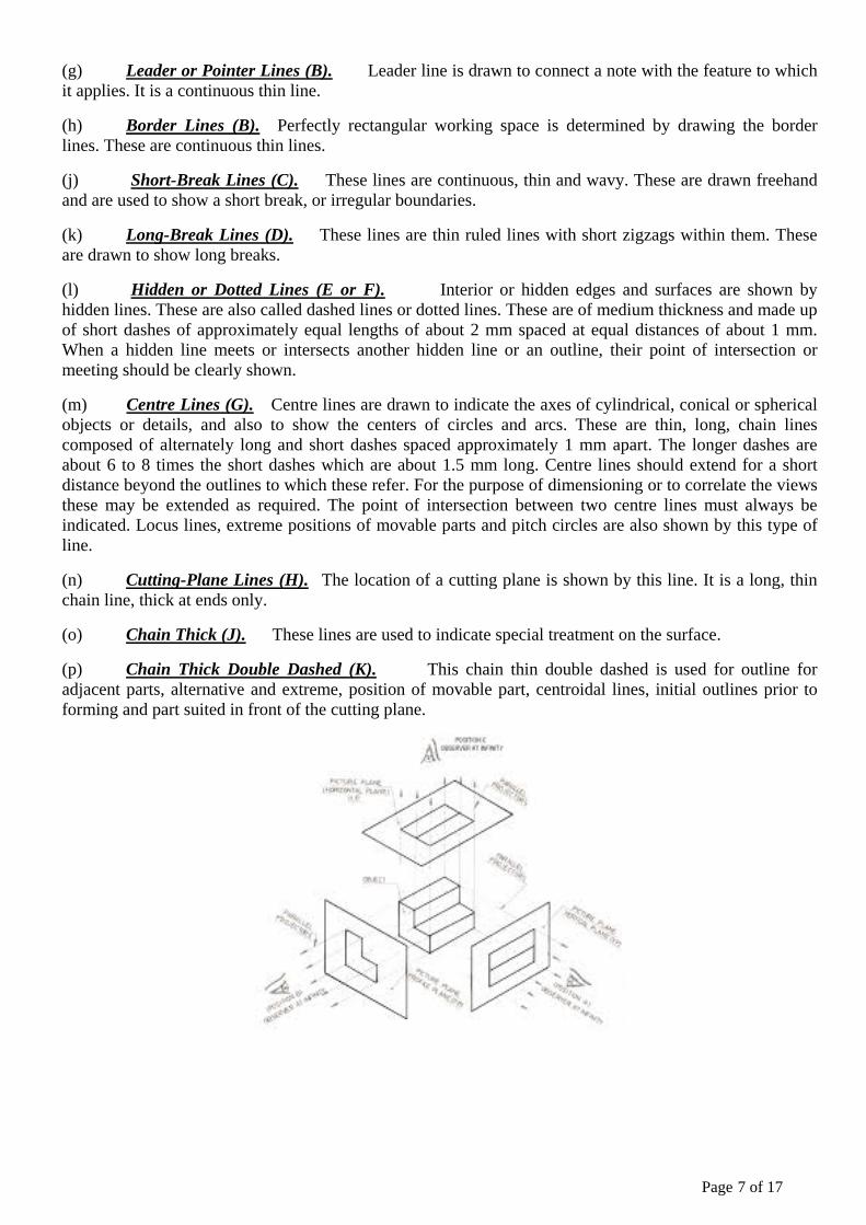
Orthographic or Multiview Drawing
Imagine that you have an object suspended by transparent threads inside a glass box, as in figure 3.
Page 8 of 17

Figure 3 - The block suspended in a glass box
Then draw the object on each of three faces as seen from that direction. Unfold the box (figure 4) and you have the three views. We call this an "orthographic" or "multiview" drawing.
Figure 4 - The creation of an orthographic multiview drawing
Figure 5 shows how the three views appear on a piece of paper after unfolding the box.
Figure 5 - A multiview drawing and its explanation
Which views should one choose for a multiview drawing? The views that reveal every detail about the object. Three views are not always necessary; we need only as many views as are required to describe the object fully. For example, some objects need only two views, while others need four. The circular object in figure 6 requires only two views.
Figure 6 - An object needing only two orthogonal views
Page 9 of 17
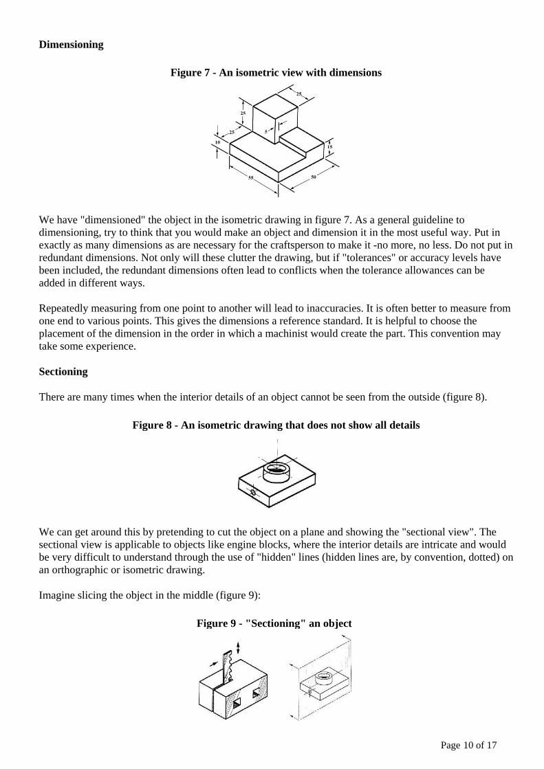
Dimensioning
Figure 7 - An isometric view with dimensions
We have "dimensioned" the object in the isometric drawing in figure 7. As a general guideline to dimensioning, try to think that you would make an object and dimension it in the most useful way. Put in exactly as many dimensions as are necessary for the craftsperson to make it -no more, no less. Do not put in redundant dimensions. Not only will these clutter the drawing, but if "tolerances" or accuracy levels have been included, the redundant dimensions often lead to conflicts when the tolerance allowances can be added in different ways.
Repeatedly measuring from one point to another will lead to inaccuracies. It is often better to measure from one end to various points. This gives the dimensions a reference standard. It is helpful to choose the placement of the dimension in the order in which a machinist would create the part. This convention may take some experience.
Sectioning
There are many times when the interior details of an object cannot be seen from the outside (figure 8).
Figure 8 - An isometric drawing that does not show all details
We can get around this by pretending to cut the object on a plane and showing the "sectional view". The sectional view is applicable to objects like engine blocks, where the interior details are intricate and would be very difficult to understand through the use of "hidden" lines (hidden lines are, by convention, dotted) on an orthographic or isometric drawing.
Imagine slicing the object in the middle (figure 9):
Figure 9 - "Sectioning" an object
Page 10 of 17
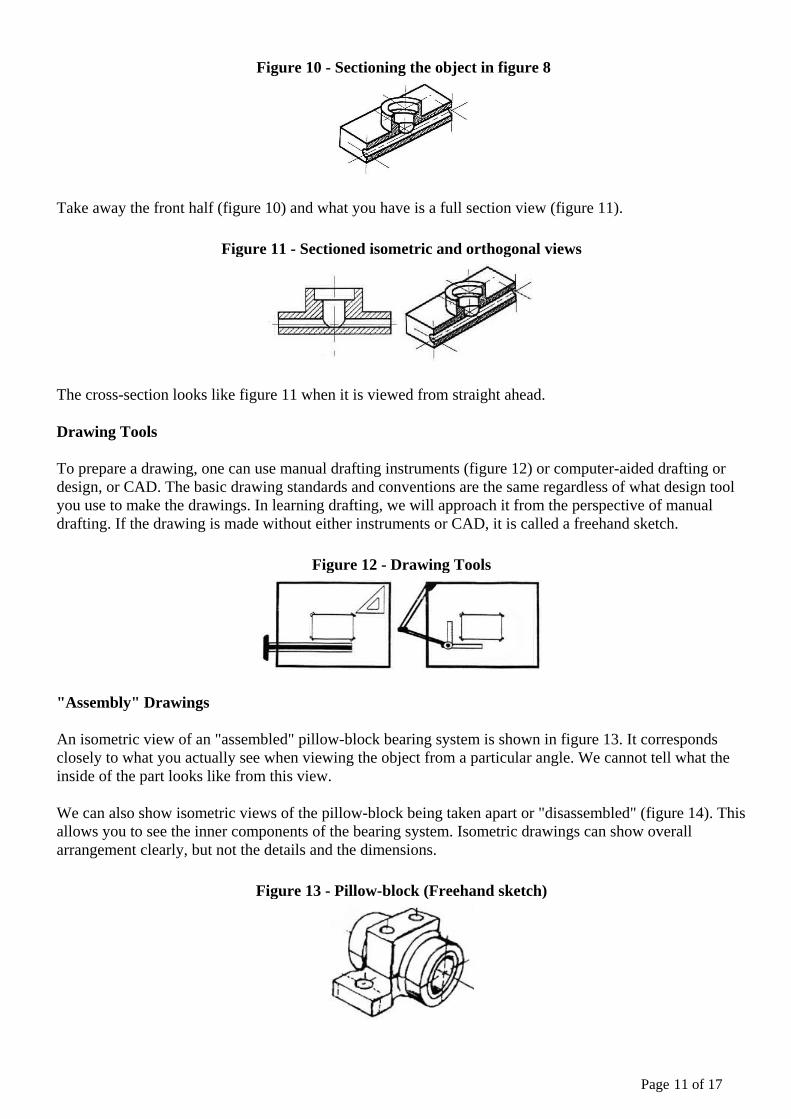
Figure 10 - Sectioning the object in figure 8
Take away the front half (figure 10) and what you have is a full section view (figure 11).
Figure 11 - Sectioned isometric and orthogonal views
The cross-section looks like figure 11 when it is viewed from straight ahead.
Drawing Tools
To prepare a drawing, one can use manual drafting instruments (figure 12) or computer-aided drafting or design, or CAD. The basic drawing standards and conventions are the same regardless of what design tool you use to make the drawings. In learning drafting, we will approach it from the perspective of manual drafting. If the drawing is made without either instruments or CAD, it is called a freehand sketch.
Figure 12 - Drawing Tools
"Assembly" Drawings
An isometric view of an "assembled" pillow-block bearing system is shown in figure 13. It corresponds closely to what you actually see when viewing the object from a particular angle. We cannot tell what the inside of the part looks like from this view.
We can also show isometric views of the pillow-block being taken apart or "disassembled" (figure 14). This allows you to see the inner components of the bearing system. Isometric drawings can show overall arrangement clearly, but not the details and the dimensions.
Figure 13 - Pillow-block (Freehand sketch)
Page 11 of 17
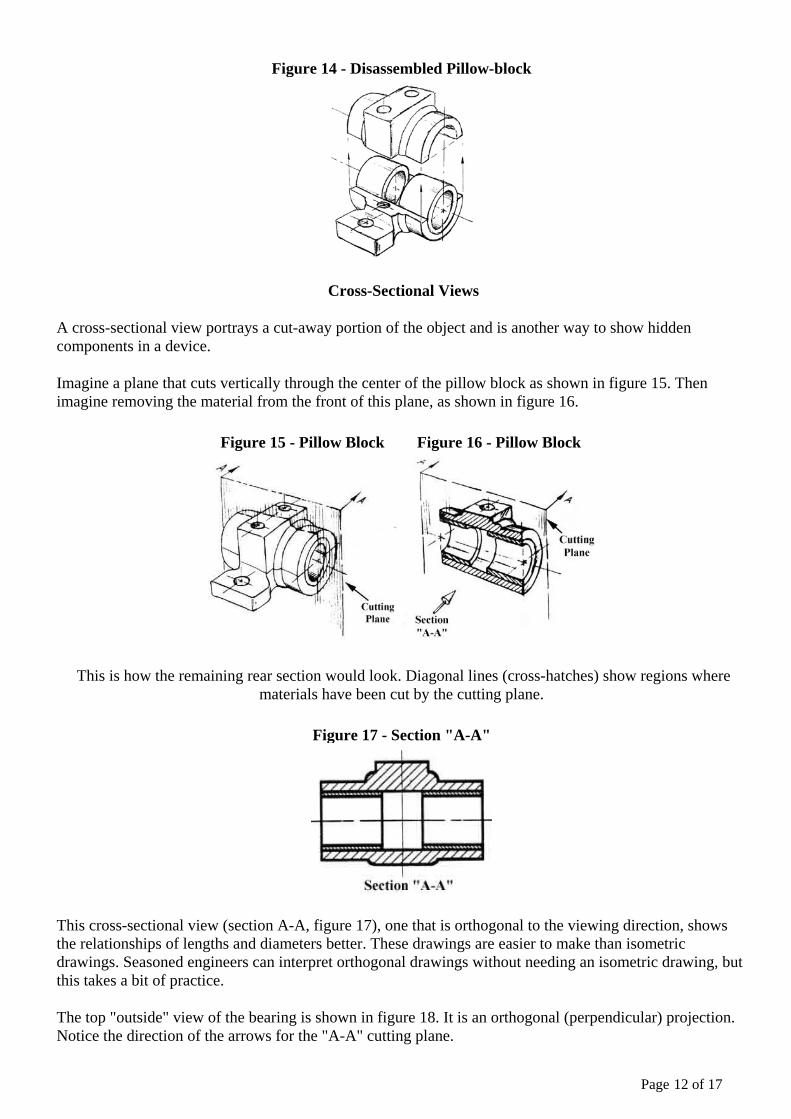
Figure 14 - Disassembled Pillow-block
Cross-Sectional Views
A cross-sectional view portrays a cut-away portion of the object and is another way to show hidden components in a device.
Imagine a plane that cuts vertically through the center of the pillow block as shown in figure 15. Then imagine removing the material from the front of this plane, as shown in figure 16.
Figure 15 - Pillow Block Figure 16 - Pillow Block
This is how the remaining rear section would look. Diagonal lines (cross-hatches) show regions where materials have been cut by the cutting plane.
Figure 17 - Section "A-A"
This cross-sectional view (section A-A, figure 17), one that is orthogonal to the viewing direction, shows the relationships of lengths and diameters better. These drawings are easier to make than isometric drawings. Seasoned engineers can interpret orthogonal drawings without needing an isometric drawing, but this takes a bit of practice.
The top "outside" view of the bearing is shown in figure 18. It is an orthogonal (perpendicular) projection. Notice the direction of the arrows for the "A-A" cutting plane.
Page 12 of 17
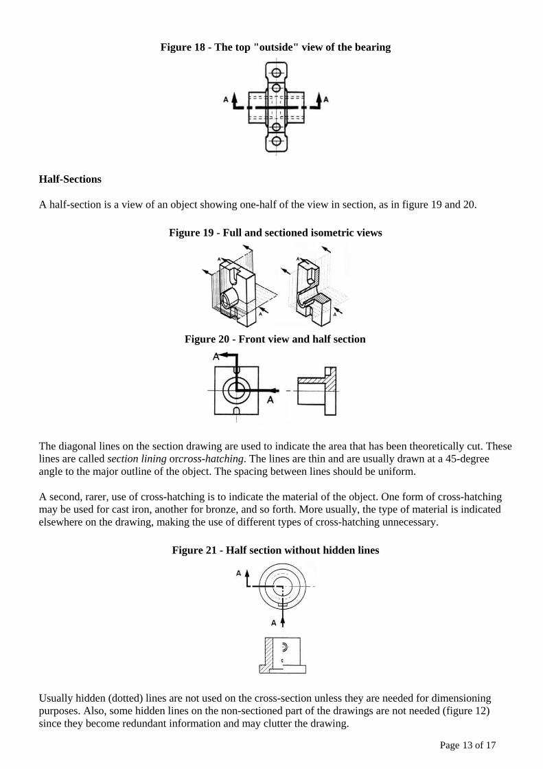
Figure 18 - The top "outside" view of the bearing
Half-Sections
A half-section is a view of an object showing one-half of the view in section, as in figure 19 and 20.
Figure 19 - Full and sectioned isometric views
Figure 20 - Front view and half section
The diagonal lines on the section drawing are used to indicate the area that has been theoretically cut. These lines are called section lining orcross-hatching. The lines are thin and are usually drawn at a 45-degree angle to the major outline of the object. The spacing between lines should be uniform.
A second, rarer, use of cross-hatching is to indicate the material of the object. One form of cross-hatching may be used for cast iron, another for bronze, and so forth. More usually, the type of material is indicated elsewhere on the drawing, making the use of different types of cross-hatching unnecessary.
Figure 21 - Half section without hidden lines
Usually hidden (dotted) lines are not used on the cross-section unless they are needed for dimensioning purposes. Also, some hidden lines on the non-sectioned part of the drawings are not needed (figure 12) since they become redundant information and may clutter the drawing.
Page 13 of 17
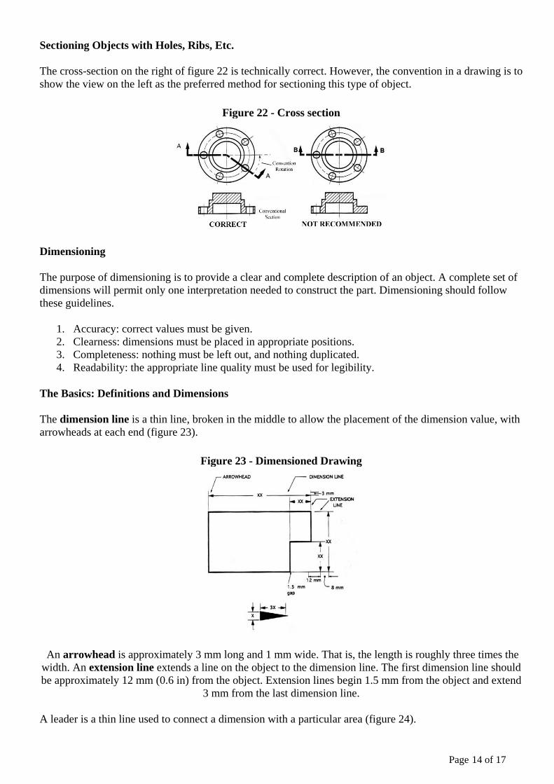
Sectioning Objects with Holes, Ribs, Etc.
The cross-section on the right of figure 22 is technically correct. However, the convention in a drawing is to show the view on the left as the preferred method for sectioning this type of object.
Figure 22 - Cross section
Dimensioning
The purpose of dimensioning is to provide a clear and complete description of an object. A complete set of dimensions will permit only one interpretation needed to construct the part. Dimensioning should follow these guidelines.
1. Accuracy: correct values must be given. 2. Clearness: dimensions must be placed in appropriate positions. 3. Completeness: nothing must be left out, and nothing duplicated. 4. Readability: the appropriate line quality must be used for legibility.
The Basics: Definitions and Dimensions
The dimension line is a thin line, broken in the middle to allow the placement of the dimension value, with arrowheads at each end (figure 23).
Figure 23 - Dimensioned Drawing
An arrowhead is approximately 3 mm long and 1 mm wide. That is, the length is roughly three times the width. An extension line extends a line on the object to the dimension line. The first dimension line should be approximately 12 mm (0.6 in) from the object. Extension lines begin 1.5 mm from the object and extend
3 mm from the last dimension line.
A leader is a thin line used to connect a dimension with a particular area (figure 24).
Page 14 of 17

Figure 24 - Example drawing with a leader
A leader may also be used to indicate a note or comment about a specific area. When there is limited space, a heavy black dot may be substituted for the arrows, as in figure 23. Also in this drawing, two holes are
identical, allowing the "2x" notation to be used and the dimension to point to only one of the circles.
Where To Put Dimensions
The dimensions should be placed on the face that describes the feature most clearly. Examples of appropriate and inappropriate placing of dimensions are shown in figure 25.
Figure 25 - Example of appropriate and inappropriate dimensioning
In order to get the feel of what dimensioning is all about, we can start with a simple rectangular block. With this simple object, only three dimensions are needed to describe it completely (figure 26). There is little choice on where to put its dimensions.
Figure 26 - Simple Object
We have to make some choices when we dimension a block with a notch or cutout (figure 27). It is usually best to dimension from a common line or surface. This can be called the datum line of surface. This eliminates the addition of measurement or machining inaccuracies that would come from "chain" or
"series" dimensioning. Notice how the dimensions originate on the datum surfaces. We chose one datum surface in figure 27, and another in figure 28. As long as we are consistent, it makes no difference. (We are
just showing the top view).
Figure 27 - Surface datum example
Page 15 of 17
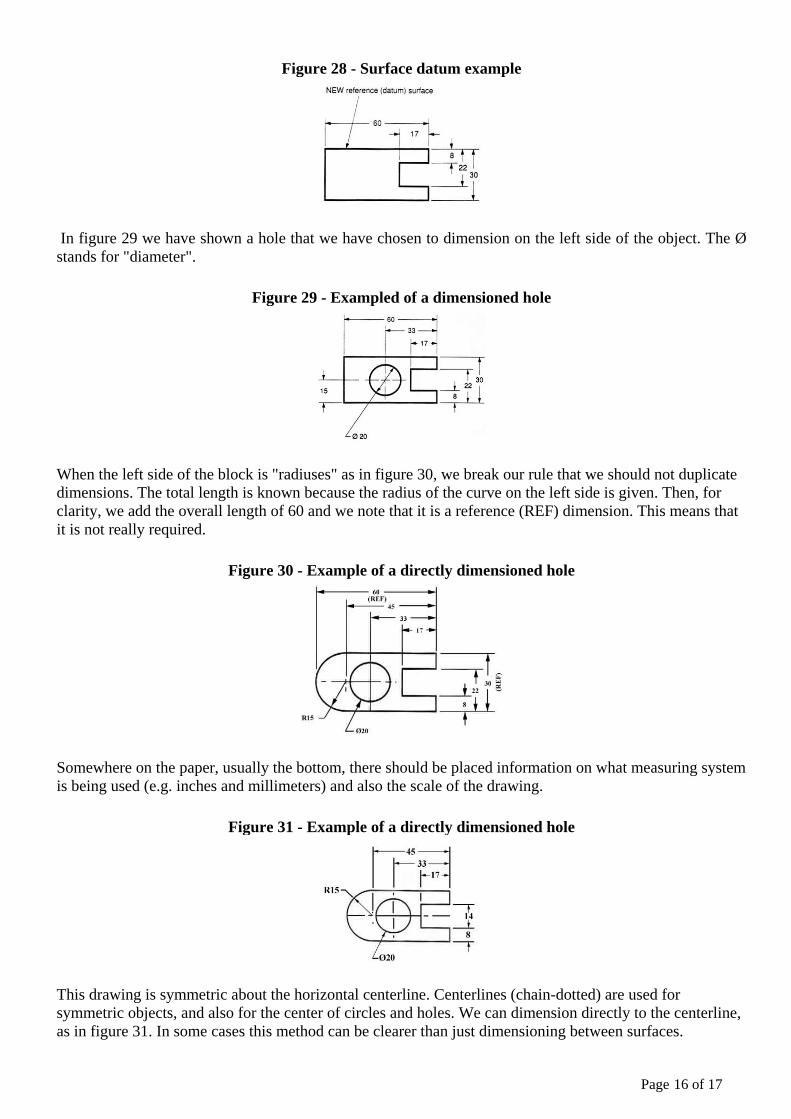
Figure 28 - Surface datum example
In figure 29 we have shown a hole that we have chosen to dimension on the left side of the object. The Ø stands for "diameter".
Figure 29 - Exampled of a dimensioned hole
When the left side of the block is "radiuses" as in figure 30, we break our rule that we should not duplicate dimensions. The total length is known because the radius of the curve on the left side is given. Then, for clarity, we add the overall length of 60 and we note that it is a reference (REF) dimension. This means that it is not really required.
Figure 30 - Example of a directly dimensioned hole
Somewhere on the paper, usually the bottom, there should be placed information on what measuring system is being used (e.g. inches and millimeters) and also the scale of the drawing.
Figure 31 - Example of a directly dimensioned hole
This drawing is symmetric about the horizontal centerline. Centerlines (chain-dotted) are used for symmetric objects, and also for the center of circles and holes. We can dimension directly to the centerline, as in figure 31. In some cases this method can be clearer than just dimensioning between surfaces.
Page 16 of 17
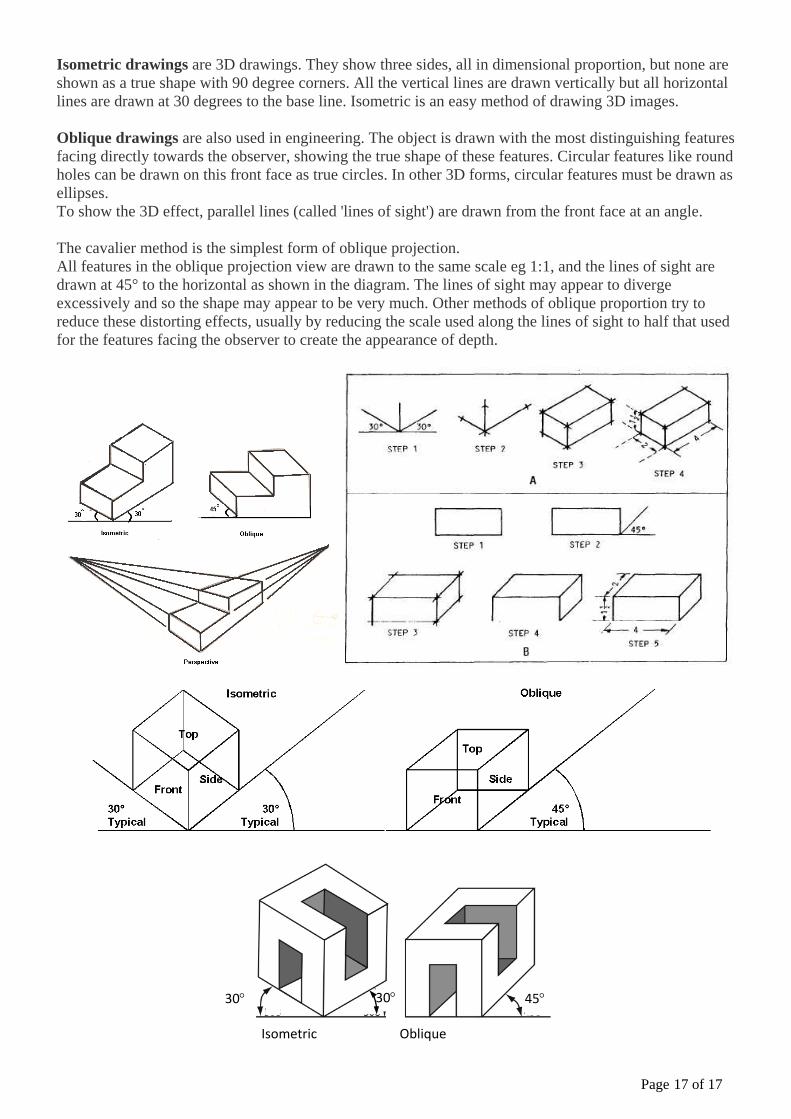
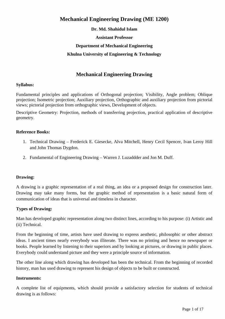
Isometric drawings are 3D drawings. They show three sides, all in dimensional proportion, but none are shown as a true shape with 90 degree corners. All the vertical lines are drawn vertically but all horizontal lines are drawn at 30 degrees to the base line. Isometric is an easy method of drawing 3D images. Oblique drawings are also used in engineering. The object is drawn with the most distinguishing features facing directly towards the observer, showing the true shape of these features. Circular features like round holes can be drawn on this front face as true circles. In other 3D forms, circular features must be drawn as ellipses. To show the 3D effect, parallel lines (called 'lines of sight') are drawn from the front face at an angle. The cavalier method is the simplest form of oblique projection. All features in the oblique projection view are drawn to the same scale eg 1:1, and the lines of sight are drawn at 45° to the horizontal as shown in the diagram. The lines of sight may appear to diverge excessively and so the shape may appear to be very much. Other methods of oblique proportion try to reduce these distorting effects, usually by reducing the scale used along the lines of sight to half that used for the features facing the observer to create the appearance of depth.
30° 45° 30°
Isometric Oblique
Page 17 of 17