Mechanical Engg. Mechanical Engg. - 3.imimg.com · PDF fileS-7 Precautions In Workshop S-9...
12
List No. 11 w.e.f. Oct. 15, 2012 Charts & Models Charts & Models Charts & Models Mechanical Engg. Mechanical Engg.
-
Upload
truongtruc -
Category
Documents
-
view
219 -
download
3
Transcript of Mechanical Engg. Mechanical Engg. - 3.imimg.com · PDF fileS-7 Precautions In Workshop S-9...
List No. 11w.e.f. Oct. 15, 2012
Charts & ModelsCharts & ModelsCharts & Models
Mechanical Engg. Mechanical Engg.

WORKSHOP CHARTS
2
1. SAFETY MEASURES
2. CARPENTRY
3. FITTING
S-1 Personal Protection
S-3 Hazchem Symbols
S-5 Fire Preventions
S-7 Precautions In Workshop
S-9 Safety on a Drilling Machine
S-11 Safety on Shaper Machine
S-13 Safety on Surface Grinder
-15 Safety in Carpentry
S-17 Safety in Foundry
WS 35 Marking Tools in Carpentry
WS 37 Types of Saws
WS 39 Types of Planes
WS 41 Holding Tools in Carpentry
WS 43 Carpentry Joints-I
WS 45 Types of Patterns
WS 61 Hacksaws
WS 63 Holding Tools (Types of Vice)
WS 65 Cutting Tools (Chisels)
WS 67 Taps and Dies
WS 69 Pipe Fittings
S-2 First Aid Materials
S-4 Ergonomics
S-6 Machine Handling Safety Measures
S-8 Safety on a Fitting Bench
S-10 Safety on Lathe Machine
S-12 Safety on Milling Machine
S-14 Safety in Press WorkSS-16 Safety in Sheet Metal Work
S-18 Safety in Welding
WS 36 Measuring Tools in Carpentry
WS 38 Types of Chisels
WS 40 Braces in Carpentry
WS 42 Hand Tools used in Carpentry
WS 44 Carpentry Joints-II
WS 51 Vernier caliper
WS 62 Wrenches
WS 64 Striking Tools (Hammer)
WS 66 Types of Files
WS 68 Reamers
I. Workshop ChartsSize 20”x26”
Thick Laminated both sides & attached with Plastic Strips Thick Laminated & Framed on NU-Wood Board
FIRE PREVENTIONS
S-5 FIRE PREVENTIONS
HAND TOOLS USED in CARPENTRY
WS 41 HAND TOOLS USED IN CARPENTRY
WRENCHESDbiosBLACKSMITHY’S HAMMERS
WS 61 WRENCHESWS 15 BLACKSMITHY’S HAMMERS
WS 70 Methods of Filling
WS 72 Forging Tools
WS 16 Blacksmith’s Tongs
WS 18 Blacksmith’s Hand tools (Chisel & Swages)
WS 20 Blacksmith’s Welds
WS 22 Flatter and Set Hammer
WS 24 Heat Treatment of Metals
WS 81 Sheet Metal Tools-II
WS 83 Types of Snips
WS 85 Shearing Machine
WS 87 Rolling Machine
WS 89 Hand Tools
WS 91 Progressive Die
WS 93 Combination Die Set
WS 101 Blast Furnace
WS 103 Foundry Hand tools-I
WS 105 Centrifugal casting
WS 107 Molding Boxes
WS 109 Magnetic Separator
WS 111 Sieve Shaker
WS 71 Hand Tools Used in Fitting shop
WS 15 Blacksmith’s Hammers
WS 17 Blacksmith’s Appliances
WS 19 Blacksmith’s Hand tools (Fullers, Punching & Drift)
WS 21 Hand Forging Operations
WS 23 Punches and Drifting
WS 80 Sheet Metal Tools-I
WS 82 SWG Chart
WS 84 Types of Joints
WS 86 Banding Machine
WS 88 Sheet Metal Process
WS 90 Blanking & Piercing Dies
WS 92 Drawing Die
WS 100 Cupola Furnace
WS 102 Electric Arc Furnace
WS 104 Foundry Hand tools-II
WS 106 Centrifugal Casting Methods
WS 108 Oil Fired Furnace
WS 110 Sand Muller
4. SMITHY
5. SHEET METAL TOOLS
6. FOUNDARY
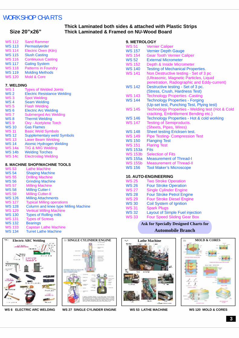
Electric ARC Welding
WS 6 ELECTRIC ARC WELDING
SINGLE CYLINDER ENGINE MOLD & CORES
WS 53 LATHE MACHINE
9. METROLOGY
10. AUTO-ENGINEERING
WS 51 Vernier Caliper
WS 154 Gear Tooth Vernier Caliper
WS 152 Depth & Inside Micrometer
WS 141 Non Destructive testing - Set of 3 pc(Ultrasonic, Magnetic Particles, Liquid penetration, Radiographic and Eddy-current)
WS 143 Technology Properties -Casting
WS 145 Technology Properties - Welding test (Hot & Cold cracking, Embritlement Bending etc.)
WS 147 Testing of Semiproducts.(Sheets, Pipes, Wires)
WS 149 Pipe Testing- Compression Test
WS 151 Flaring Test
WS 153b Selection of Fits
WS 155b Measurement of Thread-II
WS 25 Two Stroke Operation
WS 27 Single Cylinder Engine
WS 29 Four Stroke Diesel Engine
WS 31 Spark Plugs
WS 33 Four Speed Sliding Gear Box
WS 157 Vernier Depth Gauge
WS 52 External Micrometer
WS 140 Testing of Mechanical Properties.
WS 142 Destructive testing - Set of 3 pc.(Stress, Crush, Hardness Test)
WS 144 Technology Properties - Forging (Up-set test, Punching Test, Plying test)
WS 146 Technology Properties - Hot & cold working
WS 148 Sheet testing Ericksen test.
WS 150 Flanging Test
WS 153a Fits
WS 155a Measurement of Thread-I
WS 156 Tool Maker’s Microscope
WS 26 Four Stroke Operation
WS 28 Four Stroke Petrol Engine
WS 30 Coil System of Ignition
WS 32 Layout of Simple Fuel injection
3
WS 120 MOLD & CORES
WORKSHOP CHARTS
Size 20”x26” Thick Laminated both sides & attached with Plastic Strips Thick Laminated & Framed on NU-Wood Board
WS 112 Sand Rammer
WS 114 Electric Oven (Kiln)
WS 116 Continuous Casting
WS 118 Patterns in Foundry
WS 120 Mold & Core
WS 1 Types of Welded Joints
WS 3 Spot Welding
WS 5 Flash Welding
WS 7 Submerged Arc Welding
S 9 Oxy - Acetylene Torch
WS 11 Basic Weld Symbols
WS 13 Laser Beam Welding
WS 14a TIG & MIG Welding
WS 14c Electroslag Welding
WS 53 Lathe Machine
WS 55 Drilling Machine
WS 57 Milling Machine
WS 59 Milling Cutter-II
WS 127 Typical Milling operations
WS 129 Vertical Milling Machine
WS 131 Types of Screws
WS 133 Capstan Lathe Machine
WS 113 Permaslyerder
WS 115 Slush Casting
WS 117 Gating System
WS 119 Molding Methods
WS 2 Electric Resistance Welding
WS 4 Seam Welding
WS 6 Electric Arc Welding
WS 8 Thermit WeldingWWS 10 Gas Flames
WS 12 Supplementary weld Symbols
WS 14 Atomic Hydrogen Welding
WS 14b Welding Torches
WS 54 Shaping Machine
WS 56 Grinding Machine
WS 58 Milling Cutter-I
WS 126 Milling Attachments
WS 128 Column and knee type Milling Machine
WS 130 Types of Rolling mills
WS 132 Bearings
WS 134 Turret Lathe Machine
7. WELDING
8. MACHINE SHOP/MACHINE TOOLS
WS 27 SINGLE CYLINDER ENGINE
Lathe Machine
Ask for Specially Designed Charts for
Automobile Branch

Dbios Engineering graphics &drawing charts
Size 20”x26” Thick Laminated both sides & attached with Plastic Strips Thick Laminated & Framed on NU-Wood Board
II. Engineering Graphics Charts
CH 2401 1st angle and 3rd angle projections
CH 2403 Drafting Instruments
CH 3102 Convention for various materials & breaks
CH 3104 Conventional representation of springs
CH 3108 Types of Solids
CH 3111a Parallel Line Method-I
(Development of right Prism)
CH 3111c Parallel Line Method-III (Development of pipe)
CH 3113 Projection of planes.
CH 3114b Orthographic Projection-II
(Types of Pictorial Projection)
CH 2402 Drawing of different geometrical shapes
CH 3101 Description, Conventions and uses of Various Lines
CH 3103 Conventional representations of common features
CH 3107 Summary of Projections of Planes
CH 3110 Development of surfaces (Methods of development)
CH 3111b Parallel Line Method-II (Development of right Cylinder)
CH 3112 Radial Line Method(Development of right pyramid, development of right cone)
CH 3114a Orthographic Projection -I
CH 3114c Orthographic Projection-III (Comparison of first
and third Angle Projections)
(According to I.S.I 1972)
(According to ISI)
CH 3105a Position of a Points-I (Vertical & Horizontal)
CH 3106a Projection of straight line in different quadrants-I
CH 3109a Section of solids-I (Classification & Term Used)
CH 3105b Position of a Points-II (In Four Quadrants)
CH 3106b Projection of straight line summary of Projection
of straight line-II
CH 3109b Section of solids-II (Classification & Term Used)
CH 1635 Cross Head for a Horizontal Steam Engine
CH 1637 Stuffing Box for a vertical steam engine
CH 1639 Lathe tail stock
CH 1641 Petrol Engine Connecting Rod
CH 1643 Plumber Blocks
CH 1645 Foot - Step Bearing
CH 1647(I) Cotter Types
CH 1648(I) Nuts Types
CH 1649(I) Bolts Types
CH 1650(I) Rivets Types
CH 1651 Keys & Pins
(Details & Arrangement)
(Details & Arrangement)
(Details & Arrangement)(Details
& Arrangement)(Details & Arrangement)
(Details)
Spur & Bevel Terminology
(Details & Arrangement)
(Details & Arrangement)
(Details & Arrangement)
CH 1636 Cross Head for a Vertical Steam Engine
CH 1638 Tool Holder for a planning machine
CH 1640 Pipe Vice
CH 1642 Gears:
CH 1644 Angle Plumber Blocks
CH 1646 Wall Brackets
CH 1647(II) Cotter Joints
CH 1648(II) Nut Threads
CH 1649(II) Bolt Threads
CH 1650(II) Rivets Joints
III. Drawing of Mechanical Elements Charts
CH 3115 Types of Sectional views
CH 3117 Basic commands of auto CAD
CH 3119 Basic commands of CAM.
CH 3116a Important sections-I
CH 3116c Important sections-III
(Partial or broken out section, offset section, Revolved section)
(Thin Material in Section Spokes of Wheel in Section)
(Web in Section, Correct and Incorrect Section for Rib, Casting of an Object with Quater Postion Removed)
CH 3116b Important sections-II
CH 3118 Basic commands of Pro E
CONVENTIONAL REPRESENTATIONS OF COMMON FEATURES
ORTHOGRAPHIC PROJECTION
CH 3114A ORTHOGRAPHIC PROJECTION
CROSS HEAD FOR HORIZONTAL STEAM ENGINEIMPORTANT SECTIONS-I
CH 1635 CH 3116A IMPORTANT SECTIONS-I
CH 3103 REPRESENTATIONS
OF COMMON FEATURES
CONVENTIONAL
CROSS HEAD FOR HORIZONTAL STEAM ENGINE
4
5
Dbios theory of machines CHARTS
Size 20”x26” Thick Laminated both sides & attached with Plastic Strips Thick Laminated & Framed on NU-Wood Board
CH 1676 Heat Treatment Processes:
CH 1678 Iron - Carbon Diagram
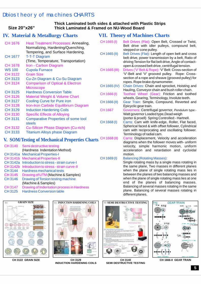
CH 3122 Grain Size
CH 3124 Comparison of Optical & Electron Microscope
CH 3126 Material Weight & Volume Chart
CH 3128 Iron-Iron Carbide Equilibrium Diagram
CH 3130 Specific Effects of Alloying
CH 3132 Cu-Silicon Phase Diagram (Cu-rich)
Annealing, Normalizing, Hardening/Quenching, Tempering, and Surface Hardening.
(Time, Temperature, Transportation) CH 1677 T-T-T Diagram
WS 100 Cupola Furnace
CH 3123 Cu-Zn Diagram & Cu-Su Diagram
CH 3125 Hardness Conversion Table
CH 3127 Cooling Curve for Pure iron
CH 3129 Induction Hardening Coils
CH 3131 Comparative Properties of some tool steels
CH 3133 Titanium Alloys phase Diagram
IV. Material & Metallurgy Charts
CH 3140 Semi destructive testing
CH 3141b Mechanical Properties-II
CH 3142b Introduction to stress - strain curve-II
CH 3145 Drawing of UTM
CH 3147 Drawing of Indentation process in Hardness
(Hardness Indentation Method)
(Machine & Samples)
(Machine & Samples)
CH 3141a Mechanical Properties-I
CH 3142a Introduction to stress - strain curve-I
CH 3144 Hardness mechanical tests
CH 3146 Drawing of Torsion testing machine
CH 3125 Hardness Conversion table
V. SOM/Testing of Mechanical Properties Charts
CH 1665 (I) Belt Drives (Flat):
CH 1665 (III) Drives (’V’ Belt & Rope):
CH 1666 (I) Toothed Wheel (Gear):
CH 1667 Governers:
CH 1668 (II) Cams:
Open Belt, Crossed or Twist, Belt drive with idler pulleys, compound belt, stepped or cone pulley.
Length of open belt and cross belt drive, power transmission by a belt, Ratio of driving Tension for flat belt drive, Angle of contact-open & crossed belt drive, centrifugal tension.
‘V’ Belt: Cross-section of ‘V’-Belt and ‘V’ grooved pulley. Rope: Cross-section of a rope and sheave (grooved pulley) for ropes. Rope brake dynamometer.
Chain and sprocket, Hoisting and Hauling, Conveyor chain and bush roller chain.
Friction and toothed wheels, Gearing, Terminology, Involute teeth.
Simple, Compound, Reverted and Epicyclic gear train.
Centrifugal governor, Pendulum type:- Watt governor Loaded type,Dead weigh (porter & proell) Spring Controlled:- Hartnell.
Cam with knife-edge, Roller, Flat faced, Spherical faced & with offset follower, Cylindrical cam with reciprocating and oscillating follower. Terminology of radial cam.
Displacement, Velocity and acceleration diagrams when the follower moves with- uniform velocity, simple harmonic motion, uniform acceleration and retardation and cycloidal motion.
Single rotating mass by a single mass rotating in the same plane, Two masses in different planes when the plane of single rotating mass lies in between the planes of two balancing masses and when the plane of single rotating mass lies at one end of the planes of balancing masses. Balancing of several masses rotating in the same plane. Balancing of several masses rotating in different planes.
CH 1665 (II) Belt Drives (Flat):
CH 1665 (IV) Chain Drives:
CH 1666 (II) Gear Train:
CH 1668 (I) Cams:
CH 1669 (I) Balancing (Rotating Masses):
VII. Theory of Machines Charts
GRAIN SIZE
CH 3122 GRAIN SIZE
INDUCTION HARDENING COILS
CH 3140 SEMI DESTRUCTIVE TESTING
CH 3129 INDUCTION HARDENING COILS
SEMI DESTRUCTIVE TESTING
CH 1666-II GEAR TRAIN

6
Production technology CHARTS
Size 20”x26”
Thick Laminated both sides & attached with Plastic Strips Thick Laminated & Framed on NU-Wood Board
CH 1669 (II) B a l a n c i n g ( R e c i p r o c a t i n g M a s s e s ) :
CH 1670 (I)b Vibration (Longitudinal & Transverse-II):
CH 1671 (I) Friction (General):
CH 1671 (III) Friction (Journal Bearing):
Reciprocating engine mechanism, primary balancing of unbalanced primary force in a reciprocating engine, reciprocating engine mechanism, primary & secondary forces, balancing of v-engines.
Types of fee vibration, natural frequency of free longitudinal, transverse vibrations. Effect of inertia of the constraint in longitudinal, transverse vibrations.
Simply supported beam with a point load. Shaft carrying a number of point loads, shaft carrying a number of point loads and uniformly distributed load, critical whirling speed of a shaft. Frequency of free damped and under damped forced vibrations. Vibration isolation.
Natural frequency of free Torsional and effect of inertia constraint on torsional vibrations, free torsional vibration of a single and tow rotor system. Torsionally equivalent shaft. Free torsional vibrations of geared system.
Limiting friction, Limiting angle of friction, Angle of repose, Minium force required to slide a body, Body lying on a rough inclined plane motion of the body up the plane neglecting & considering friction and down the plane considering friction.
Screw jack, thrust collar, torque required of lift the load, and to lower the load and friction of a V-thread.
Friction in journal bearing, Pivot and Collar bearing, flat pivot or foot step bearing, conical trapezoidal pivot bearing, flat collar bearing.
Single disc or plate clutch and its forces, cone clutch its friction surfaces as a frustrum of a cone.
CH 1670 (I)a Vibration (Longitudinal & Transverse-I):
CH 1670 (II) Vibration (Torsional):
CH 1671 (II) Friction (Screw):
CH 1671 (IV) Friction (Clutches):
VII. Theory of Machines Charts
CH 1619 (I) Gear:
CH 1620 (I) Cutting Tool:
CH 1620 (III) Cutting Tool:
CH 1621(II) Bending:
CH 1622 (II) Drill:
CH 1624 (I) Chip:
CH 1625 (I) Gauges:
CH 1625 (III) Gauges:
CH 1626 (II) Millings:
CH 3155 Elements of Jigs and Fixtures
CH 3157 Elements of Jigs and Fixtures
CH 3159 Types of Broaches
WS 134 Turret Lathe
CH 3163 Tool Geometry
Horizontal gear shaping machine-principle
Hobbing process
Basic requirements
Single point tool
Chip formation & formation of
continuous chip with a Built-up edge.
Principles, U-bending dies & Bending
tools.
V - bending dies, Bending radius
& Bending forces
Straight shank & oil hole
Drill parts
Types of counter bore, Counter
sinking & Counter drilling
Types of chip breakers & Chisel edge
angle
Automatic back spot facer
Types of gauges Gauge tolerances Gauge components Cutters terminology Broaching tools
Cutters
(Locating Devices)
(Clamping Devices)
(Indexing Devices)
Lathe and its Operations
CH 1619 (II) Gear:
CH 1620 (II) Cutting Tool:
CH 1621(I) Bending:
CH 1622 (I) Drill:
CH 1623 Counter:
CH 1624 (II) Chip:
CH 1625 (II) Gauges:
CH 1626 (I) Millings:
CH 1626 (III, IV & V) Millings:
CH 3156 Elements of jigs and Fixtures
CH 3158 Press Tools
CH 3160
CH 3162 Turret Indexing Mechanism
(Set of 2 Charts)
(Set of 2 Charts)
VIII. Production Technology Charts
PRESS TOOLSELEMENTS of JIGS and FIXTURES-I
CH 3158 PRESS TOOLSCH 3155 ELEMENTS of JIGS and FIXTURES-I
CH 1622(I) DRILL STRAIGHT SHANK DRILL
CH 1669 (II) BALANCING RECIPROCATING MASSES

IX. Metrology Quality Control Charts
CH 3174 Abrasive Jet machining
CH 3176 Electron Beam Machining
CH 3178 Laser Beam Machining
(AJM)(ECM)
(EBM)
(EDM)
(LBM)
(PAM)
CH 3175 Electro Chemical Machining
CH 3177 Electrical Discharge Machining
CH 3179 Plasma Arc Machining
X. Advance Manfu Tech./ Process cturing Charts
7
Metrology quality control CHARTS
Size 20”x26” Thick Laminated both sides & attached with Plastic Strips Thick Laminated & Framed on NU-Wood Board
CH 3164 Tool layout of Turret Lathe
CH 3166 Turret Tool holders
CH 3168 Jig Boring Machine
CH 3170 Gear Hobbing Machine
CH 3172 Types of Collect Chuck
CH 3174 Abrasive Jet machining CH 3175 Electro Chemical Machining
CH 3177 Electrical Discharge Machining
CH 3179 Plasma Arc Machining
CH 3181 Different shapes of Grinding Wheels
CH 3183 Broaching Operations
CH 3185 Sensitive & Vertical Drilling Machine
CH 3165 Shaping Machine
CH 3167 Broaching Machine
CH 3169 Superfinishing Processes
CH 3171 Variable Speed Drive
CH 3173 Types of Cutter Holder & Work holder In Milling Machine
CH 3176 Electron Beam Machining
CH 3178 Laser Beam Machining
CH 3180 Methods of Metal Cutting
CH 3182 Quick Return Mechanism of a Shaper Machine
CH 3184 Parts of Standard Shaper
CH 3186 Radial Drilling Machine
(Construction)
(Type / Construction)
(ECM)(EBM)
(EDM)(LBM)
(PAM)
(Orthogonal / Oblique)
VIII. Production Technology Charts
CH 3200 Standards of Measurements & Methods of Measurement
CH 3202 Surface Plates, Beam comparator, Spirit Levels & Combination set.
CH 3204 Vernier Caliper & Types of vernier caliper.
CH 3206 Slip Gauges.
CH 3208 Type of Comparator
CH 3201 Non Precision Measuring tools
CH 3203 Universal Surface Gauge & Engineer’s Square.
CH 3205 Types of Micrometer.
CH 3207 Plain Plug Gauges, Snap & Limit.
CH 3209 Mechanical optical, Electro-Mechanical & Pneumatic Comparator
CH 3210 Solex pneumatic Gauges & Differential Comparator
CH 3212 Types of Bevel Protectors
CH 3214 Manufacturing Process & Expected values of
Roughness.
WS 155 Measurement of Threads
CH 3218 Gear Tooth Measurement
CH 3220 Measurement of Gears using Gratings
CH 3211 Geometric Characteristics & Symbol
CH 3213 Types Auto collimator
CH 3215 Dial Gauge Indicator, Applications.
CH 3217 Thread Gauges
CH 3219 Spur Gear Testes
CH 3221 Surface Roughness measurement
XI CAD / CAM ChartsCH 3255 Hierchy of computer in Manufacturing
CH 3257 Computer integrated production planning & control system
CH 3259 Computer aided Process Planning
CH 3261 Computer-Process Control
CH 3263 CNC Milling
CH 3118 Basics commands of Pro-E
CH 3256 Computer network structures
CH 3258 Computer integrated production management system.
CH 3260 Robot Technology
CH 3262 CNC Turning
CH 3117 Basics commands of Auto CAD
CH 3119 Basics commands of CAM
SHAPING MACHINE
CH 3165 SHAPING MACHINE
ELECTROCHEMICAL MACHINING CNC TURNING
CH 3201 NON PRECISION MEASURING TOOLS
CH 3175 ELECTROCHEMICAL MACHINING
NON PRECISION MEASURING TOOLS
CH 3262 CNC TURNING

XIII. Therodynamics / Thermal ChartsHEAT & THERMODYNAMICS
CH 3270 Babcock and Wilcox Boiler
CH 3272 Velox Boiler
CH 3274 Jet Condensers
CH 3276 Separating Calorimeter
CH 3278 Combined Separating and throttling Calorimeter
CH 3280 Different types of Cycles
CH 3282 Wankle Engine With Cycle
CH 3284 Stirling Engine
CH 3271 Loeffler Boiler
CH 3273 Green’s Economiser
CH 3275 Surface Condensers
CH 3277 Throttling Calorimeter
CH 3279 Mollier Diagram
CH 3281 Heat pump
WS 31 Spark Plug
CH 3285 Compressors (Reciprocating and rotary)
8
Fluids machines & hydraulics CHARTS
Size 20”x26”
Thick Laminated both sides & attached with Plastic Strips Thick Laminated & Framed on NU-Wood Board
CH 1655 Pressure Measuring Devices:
CH 1656(II) Reaction Turbine (Radial & Axial Flow):
CH 1657 (II) Fluid System:
CH 1658 Orifices & Mouthpieces:
CH 1660 Flow In Channels (Open):
Relationship; Simple Manometer: Piezometer, U- tube (for gauge & vaccum pressure) and single column manometer - vertical & inclined, Differential Manometer: U-tube differential & inverted U-Tube differential
Layout of a hydroelectric power plant, nozzle with a spear to regulate flow, Pelton turbine, Governing of pelton turbine & Runner of Pelton wheel.
Main parts of a radial reaction turbine, Inward & Outward radial flow turbine, Kaplan turbine runner & its main components.
(Principles of fluid statics & kinematics)Hydraulic press, Actual Hyd. Press, Hyd. Accumulator, Differential Hyd. Accumulator.
(Principles of fluid statics & kinematics)Hyd. Intensifier, Hyd. Ram & Hyd. Lift
(Principles of fluid statics & kinematics)Hyd. Crane, Hyd. Coupling, Hyd. Torque Converter
Tank with an or i f ice, Hyd. Coeff ic ient (experimentally), External cylindrical, Convergent- Divergent mouthpieces.
Rectangular, Triangular, Trapezoidal & Stepped.
Cipolletti, Broad crested, An Oogee & submerged.
Uniform & non-uniform flow and uniform flow in open channel, specific energy and its curve, Hydraulic jump, Backwater curve and affux & its length.
: Sudden enlargement & contraction, An obstruction, Syphon, Compound, parallel & branched pipes, power transmission through nozzle.
CH 1656 (I) Impulse Turbine (Tangential Flow):
CH 1657 (I) Fluid System:
CH 1657 (III) Fluid System:
CH 1659 Notches & Weirs:Notches:
Weirs:
CH 1661 Flow Through Pipes (Minor energy losses)
XII. Fluids Machines & Hydraulics ChartsCH 1662 Pumps (Centrifugal):
CH 3233 Types of Acting Cylinder
CH 3235 Directional control valve
CH 3237 Types of Flow Control Valve
CH 3239 Pilot Operated Directional Control Valve
Main parts, Different casings, pumps in parallel & series (Two stages)
Main parts, Velocity & acceleration, Indicator diagrams, Air vessel fitted.
CH 1663 Pumps (Reciprocating):
CH 3232 Various Types of Pump (Gear Pump)
CH 3234 Pneumatic Tools
CH 3236 Comparison of Seat Valves , Types of Spool &
Seat Valves
CH 3238 Impulse Generator
CH 3240 Solenoid Operated valve
TYPES OF ACTING CYLINDER
CH 3233 TYPES OF ACTING CYLINDER
STIRLING ENGINETYPES OF FLOW CONTROL VALVE
CH 3284 STIRLING ENGINE
CH 3237 TYPES OF FLOW CONTROL VALVE
CH 1657(II) FLUID SYSTEM IIPRINCIPLES OF FLUID STATICS & KINEMATICS

XV. Internal Combustion Engine Charts CH 1601 Main Refrigerant Lines for refrigeration system
CH 1603 Use of an oil separator in a refrigeration system
CH 1605 Compression cycle in a rotary compressor
CH 1607 Air cooled condenser
CH 1609 Water-cooled condenser
CH 1611 Oil skimmer on flooded shell and tube evaporator
CH 1613 Types of mechanical draft cooling towers
CH 1615 Natural Draft Cooling Tower- Hyperbolic Cross Flow Type
CH 1618 Refrigerant Conditions in Typical A.C. Unit.
CH 3322 Steam Jet Refrigeration
CH 3324 Desart Cooler & Water Cooler
CH 3326 Indirect Refrigeration System
CH 3328 Hermetic Sealed Compressor
CH 1602 Basic vapour compression refrigeration system
CH 1604 Refrigeration compressors:
CH 1606 Single acting reciprocating compressor:
CH 1608 Evaporative condenser:
CH 1610 Multiple evaporator system with a central accumulator
CH 1612 Spring loaded pressure relief valves
CH 1614 Atomospheric natural draft cooling tower
CH 1616 Psychometric Chart
CH 3321 Layout of Ice Plant
CH 3323 Vortex tube Refrigeration
CH 3325 Types of Compressors
CH 3327 Evaporating Cooling
CH 3329 Constant Pressure Expansion valve
Reciprocating, Rotary, Helical (screw) & Centrifugal
Piston at top of cylinder, down stroke, piston at bottom of cylinder & Upstorke
Counter flow draw-through type & Below-through type
Shell and coil & Tube in tube
Splash Deck type and Spray Type
XIV. RAC Charts
9
XVI. Heat Transfer Section ChartsCH 3341
CH 3343 Heat Transfer in Natural Convection
CH 3345 Extended Surfaces
CH 3347 Types of Heat Exchanger
CH 3349 Pool Boiling Phenomenon
CH 3351 Thermal Conductivity of Metal Bar
CH 3353 Properties of Air
CH 3356 Heat Exchange Equipment
Thermal Conductivity of Insulating PowderCH 3342 Two Slab Guarded Hot Plate apparatus
CH 3344 Heat Transfer in Forced Convection
CH 3346 Stefan Boltzman Apparatus
CH 3348 Shell & Tube Heat Exchanger
CH 3350 Heat pipe
CH 3352 Heat Transfer in Condensation
CH 3354 Properties of Saturated Water
Rac CHARTS
Size 20”x26” Thick Laminated both sides & attached with Plastic Strips Thick Laminated & Framed on NU-Wood Board
WS 25 Two Stroke Cycle
WS 31 Spark Ignition
CH 3299 Fuel Ignition Systems
CH 3301 Combustion Chamber
CH 3303 Types of Lubricator
CH 3305 Types of Calorimeter
CH 3307 Working of Car Compressor
CH 3309 Cooling System in Automobile
CH 3311 Catalytic Converter
WS 26 Four Stroke Cycle
CH 3298 Fuel Injection Systems
CH 3300 Types of Carburesttors
CH 3282 Wankle Engine with Cycle
CH 3304 Bomb Calorimeter
CH 3306 Flash & Fire point apparatus
CH 3308 Gas Turbine Plant
CH 3310 Exhaust System
(2 Stroke/4 Stroke)
XVII. Renewable Source Charts CH 3
CH 3412 Energy sources
CH 3414 Comparison chart for renewable energies.
CH 3416 Hydropower renewable energy
CH 3418 Geothermal renewable energy
410 Plant Layout from waste CH 3411 Fuel Generation from Garbage
CH 3413 Renewable Energy Resources
CH 3415 Biomass renewable energy
CH 3417 Wind power renewable energy
CH 3419 Solar renewable energy
BASIC VAPOUR-COMPRESSION REFRIGERATION SYSTEM
CH 1602 VAPOUR-COMPRESSION
REFRIGERATION SYSTEM
BASIC
TYPES OF CARBURETORS STIRLING ENGINE
CH 3345 DIFFERENT EXTENDED SURFACE
CH 3350 STIRLING ENGINE
CH 3300 TYPES OF CARBURETORS
DIFFERENT EXTENDED SURFACE

XX. Non Destructive Testing Charts CH 3
CH 3402 Liquid Penetration Testing
CH 3404 Eddy-current Testing
400 Ultrasonic TestingCH 3401 Magnetic particle testing
CH 3403 Radiographic
XXI. Fibre Reinforced Plastics Charts CH 3445 Applications of Fibre Reinforced Plastics
CH 3446 Different processes of FRP (set of 5Pc)
(Filament winding, pultrusion, RTM &
VARTM, SMC, BMC , Bladder
moulding etc)
10
Automobiles CHARTS
Size 20”x26”
Thick Laminated both sides & attached with Plastic Strips Thick Laminated & Framed on NU-Wood Board
XVIII. Automobiles Charts
CH 1627 Differential
CH 1629 Hydraulic Brake Layout
CH 1631 Fuel Feed Pump Petrol
CH 1671 (II) Friction (Screw):
CH 3372 Multi Cylinder Diesel Engine
CH 3374 The Ferlec Electro-Magnetic Clutch
CH 3376 Multiple plate clutch
CH 3378 Single Plate Clutch
CH 3380 Disc Brake
CH 3382 Power Operated Brakes
CH 3384 Details of Generator Cum Alternator
WS 31 Spark Plug
CH 3388 Types of Lubricating Pump
CH 3390 Automobile Electrical circuit
CH 1628 Single Plate Clutch
CH 1630 Wheel Alignment
CH 1632 Electric Fuel Feed PumpCH 1671 (I) Friction (General):
CH 3371 Multi Cylinder Petrol Engine
CH 3373 Types of Air Filter
CH 3375 Principle of Centrifugal Clutch
CH 3377 Diaphragm Spring Clutch
CH 3379 Internal Expanding Brake System
CH 3381 Master Cylinder
CH 3383 Duel Power operated Brake System
CH 3385 Power Transmission Line Layout
CH 3387 Shock Absorber
CH 3389 Automobile Lighting system
Limiting friction, Limiting angle of friction, Angle of repose, Minium force required to slide a body, Body lying on a rough inclined plane motion of the body up the plane neglecting & considering friction and down the plane considering friction.
Screw jack, thrust collar, torque required of lift the load, and to lower the load and friction of a V-thread.
XIX. Rapid Prototyping Charts CH 3431 Stereo lithography
CH 3433 Laminated Object Manufacturing
CH 3435 Solid Ground Curing CCH 3437 Three dimensional printing
CH 3439 Inkjet-based Technologies
(SLA)(FDM)
(LOM)(SLS)
(SGC)(BPM)
(3DP)(LPF)
(IBT)
CH 3432 Fused Deposition Modelling
CH 3434 Selective Laser sintering
H 3436 Ballistic Particle Manufacturing
CH 3438 Laser Powder Forming
CH 3440 Comparison chart of Rapid protyping processes
EDDY-CURRENT TESTING RADIOGRAPHIC
CH 3404 EDDY-CURRENT TESTING
CH 3403 RADIOGRAPHICCH 1627 DIFFERENTIAL CH 1628 SINGLE PLATE CLUTCH
Ask for Specially Designed Charts
Size 30”X40”
for Automobile Branch

11
ENGINEERING MODELS
MODELS on NUTS & BOLTS
DM 100 DISSECTED MODELS on DRAWING Cube, Cone, Sphere & Cylinder Prism & Pyramid {Rectangular, Triangular Square, Pentagonal & Hexagonal}.
DM 105 NON-DISSECTED MODELS on DRAWING Cube, Cone, Hemi-sphere, Sphere, Tetrahedron, Octahedron, Semi-Cylinder & Cylinder. Prism & Pyramid {Rectangular, Triangular Square, Pentagonal & Hexagonal}.
DM 110 DISSECTED MODELS on SOLIDS Cone cut at an Oblique; Cylinder cut in two Hemi-sphere; Sphere cut into two Hemi-spheres; Cubecut in two right angled Triangles; Triangular prism cut in two parts parallel to base; Pyramid triangular cut in two parts; Parallelepiped dissectable in two triangular prisms; Tetrahedron cut in two parts parallel to base.
DM 115 INTERSECTION of SOLIDS Two Cylinders at Right angles; A cylinder into cone. Two Cylinders with oblique penetration. A cone & cylinder penetrating at right angles A cylinder into cone at right angles. Two cones at right angles, Sphere & cone at centre. Two square prisms at oblique angles. Sphere & Cone At eccentric, Sphere & cylinder at centre.
DM 125 Different types of NUTS Hexagonal, Square, Flanged, Cap, Dome, Ring, Wing, Capstan & Cylindrical Nuts.
DM 130 Different types of BOLT HEADS Hex ,Square, Round, Cheese, Flat, Pan, Oval & Flister.
DM 135 Different types of THREADS Triangular or ‘V’ ,Square, Whitworth, Metric, Acme, Metric Trapezoidal, Knuckle and Buttress Threads.
(set of 14)
(set of 18)
(set of 8)
(set of 10)
(set of 10)
(set of 8)
(set of 8)
In our Continuous pursuit to unrivaled quality now join Hands and Heads with to cater your Laboratory/Workshop needs under one roof.
Dbios, Ambros
DM 251 DM 110
DISSECTED MODELS on SOLIDS
WORKSHOP mODELS
DM 125DIFFERENT TYPES OF NUTS 4 STROKE PETROL ENGINE
DM 250 2 Stroke Petrol Engine
DM 251 4 Stroke Petrol Engine
DM 252 2 Stroke Diesel Engine
DM 253 4 Stroke Diesel Engine
SECTIONAL WORKING MODELS on PETROL & DIESEL ENGINE
INNOVATIONS REWARDING Registration Open: Jan 1, 2013 Registration End: Feb 15, 2013
Dbios unveils an opportunity for budding technocrats to exhibit their technical skills. Project guide may hone the skills of their wards and send their best entries as this is Inter-Collegiate competition. We invite final year B.Tech Mechanical Engg. students to forward their project as per asked details latest by Feb 15, 2013. Their Projects would be judged by the subject specialists going through minute details of the topic.
Dbios announces a rewarding Innovations scheme for the young engineers.
Prize Amount Team/Individual Supervisor/ Guide
First Prize: 10000/- [5000/-] [5000/-]
Second Prize: 5100/- [3100/-] [2000/-]
Third Prize 3100/- [2100/-] [1000/-]
Regis ration fees t
s. 500/-R
Certificates would be given to all registered participants including their supervisors

WORKSHOP pioneers
James Watt
James Watt
DME 19 M. Visvesvaraya
DME 20 E. Sreedharan
SP 13 Galileo Galilei
SP 14 Issac Newton
SP 15 C. V. Raman
SP 16 H.J. Bhabha
SP 20 Archimedes
SP 23 Albert Einstein
SP 44 Dr. A. P. J. Abdul Kalam
SP 45 Anton Van Ieeuwenhoek
SP 46 Thomas Alva Edison
SC 27 Gilbert Newton Lewis
DE 04 Alexander Graham Bell
DE 11 Max Plank
DME 1 James Watt
(Father of Mechanical Engineering)
DME 2 Lord Vishwakarma
DME 3 Lord Brahma
DME 4 Rudolph Diesel
DME 5 Kelvin
DME 6 Aryabhatta
DME 7 Taylor
DME 8 Wright brothers
DME 9 George Stephenson
DME 10 Nicholes Otto
DME 13 Dunlop
DME 15 J. M. Juran
DME 17 Rober Boyle
DME 18 Benjamin Franklin
DME 1James Watt
Pioneers of Mechanical Engineering
11”x16”
16”x22”
Laminated & Framed on NU-Wood Board
Small size 12”x18” Medium size 16”x21” Big size 20”x26”