

MECHANICAL CONDITION MONITORING ON ROTARY KILNS · Measurement Tools for the Cement Industry...
57
Measurement Tools for the Cement Industry MECHANICAL CONDITION MONITORING ON ROTARY KILNS
Transcript of MECHANICAL CONDITION MONITORING ON ROTARY KILNS · Measurement Tools for the Cement Industry...

Measurement Tools for the Cement Industry
MECHANICAL CONDITION MONITORING ON ROTARY KILNS

Agenda
•About TomTom-Tools GmbH
•New Kiln Axis Alignment System
•Tablet PC with Long Range Bluetooth
•Ovality Sensor
•Inductive Distance Measurement (IDM) Tool Kit
Gear Run-Out Measurement
Roller Shaft Bending Measurement
•Mechanical Kiln Monitoring (MKM) System
•Measuring Wheel
•Rotary Inclinometer
•Kiln Shell Laser + Rotation Trigger
•Telescopic Contact Thermometer
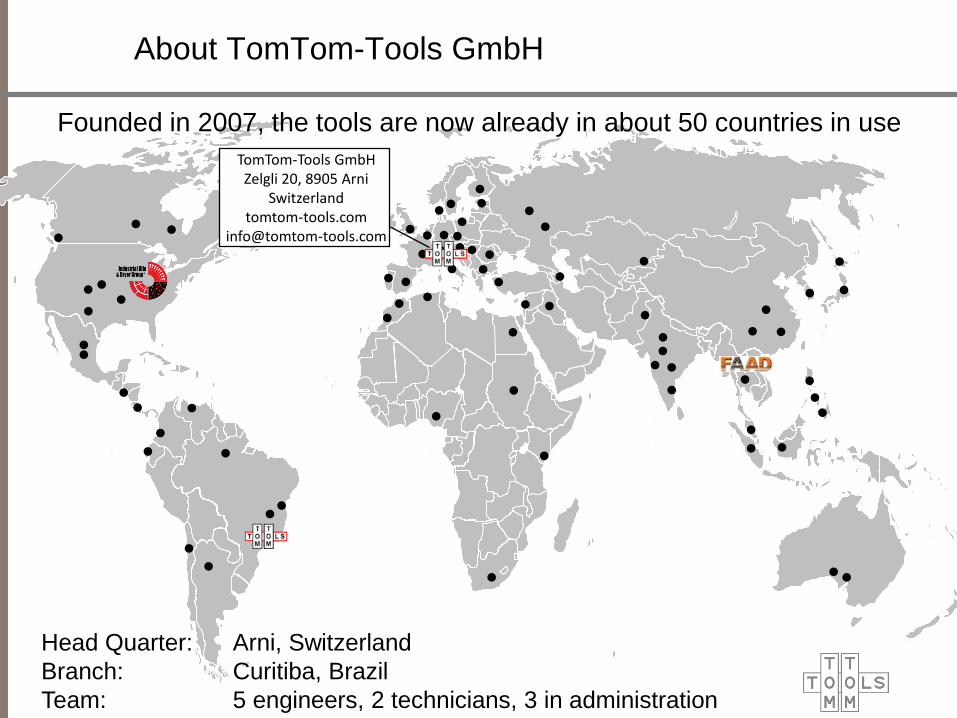
TomTom-Tools GmbH Zelgli 20, 8905 Arni
Switzerland tomtom-tools.com
Head Quarter: Arni, Switzerland
Branch: Curitiba, Brazil
Team: 5 engineers, 2 technicians, 3 in administration
Founded in 2007, the tools are now already in about 50 countries in use
About TomTom-Tools GmbH
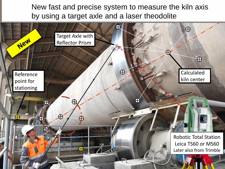
New fast and precise system to measure the kiln axis
by using a target axle and a laser theodolite
Target Axle with Reflector Prism
Calculated kiln center
Reference point for stationing
Robotic Total Station Leica TS60 or MS60
Later also from Trimble

Kiln Axis Measurement System Overview
Typically 2 stationing of theodolite are sufficient
Reference point for stationing
Assistant with Target Axle
Calculated kiln center
Main Operator with Robotic Total Station

The ball reflectors make the measurement easy,
precise and fast
Target Axle on kiln tire
Reference point distributed around the kiln
for re-stationing of theodolite Target on shaft center with Rotation Adapter
The target catching function of the theodolite find and measure the targets quickly. It does not require precise targeting by the operator

The results of the measurement is the value how much to
move the rollers to get the kiln straight
Kiln Axis deviation: Expected center determination accuracy: +/- 1mm (depending on accuracy of laser theodolite)
Side View
Top View
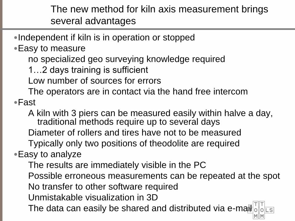
The new method for kiln axis measurement brings
several advantages
•Independent if kiln is in operation or stopped
•Easy to measure
no specialized geo surveying knowledge required
1…2 days training is sufficient
Low number of sources for errors
The operators are in contact via the hand free intercom
•Fast
A kiln with 3 piers can be measured easily within halve a day, traditional methods require up to several days
Diameter of rollers and tires have not to be measured
Typically only two positions of theodolite are required
•Easy to analyze
The results are immediately visible in the PC
Possible erroneous measurements can be repeated at the spot
No transfer to other software required
Unmistakable visualization in 3D
The data can easily be shared and distributed via e-mail
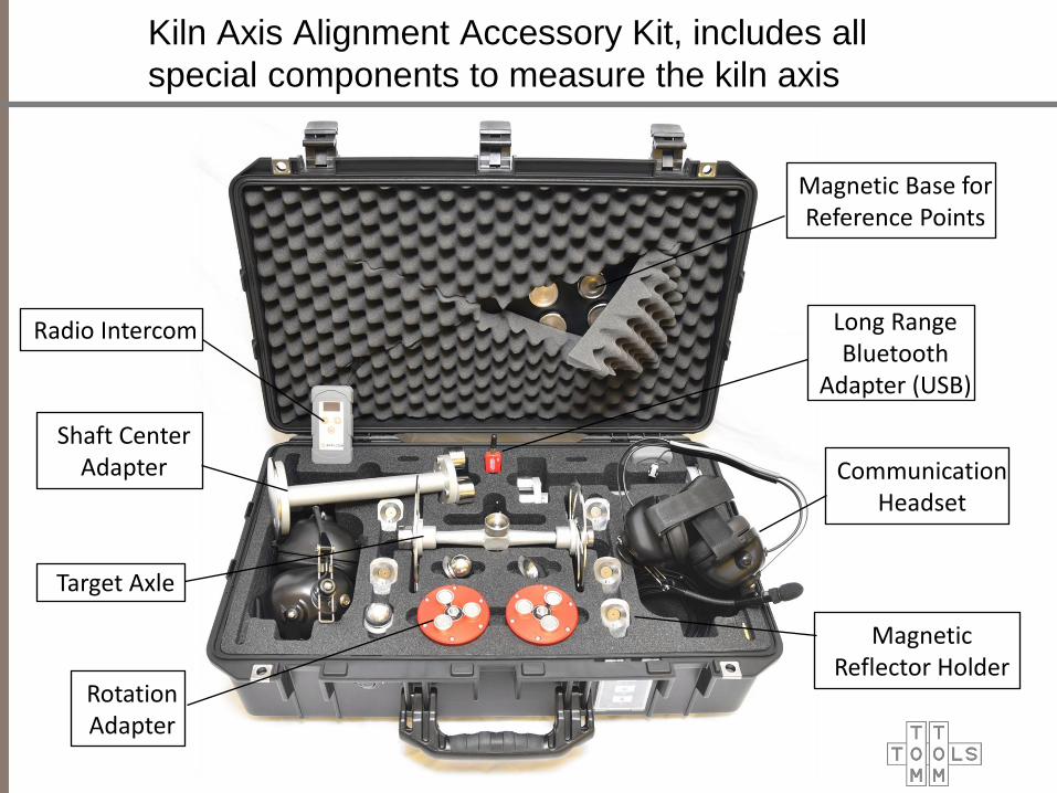
Kiln Axis Alignment Accessory Kit, includes all
special components to measure the kiln axis
Communication Headset
Shaft Center Adapter
Magnetic Base for Reference Points
Magnetic Reflector Holder
Radio Intercom
Target Axle
Rotation Adapter
Long Range Bluetooth
Adapter (USB)
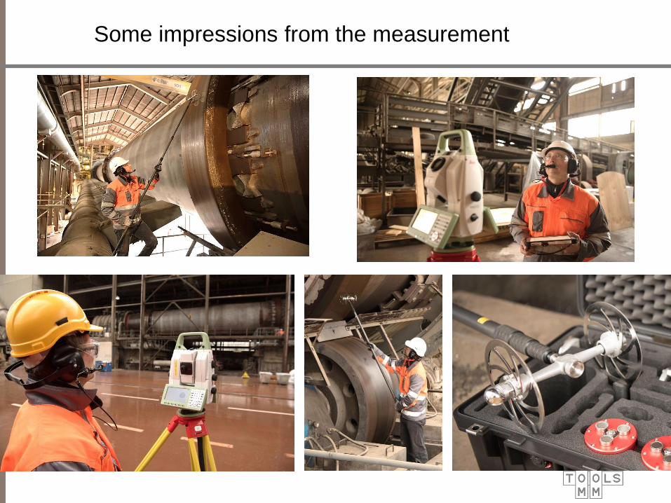
Some impressions from the measurement

Day 1:
• Measurement of kiln axis
• Deviation detected
(Tire 2: 4mm left, 7mm down)
• Recommended correction: move left roller
of pier 2 by 8mm towards kiln center
Example: Kiln axis alignment measurement,
correction and confirmation
Day 2:
• Performed Correction:
Left roller of pier 2 was moved by
6.7mm towards kiln center
• The kiln axis was measured again
and found well within tolerance
11

Industrial Tablet PC, Panasonic TOUGHPAD
FZ-G1 with Long Range Bluetooth
•The special TomTom Bluetooth Adapter makes the Tablet
PC to match perfectly to the kiln measurement tools

Ovality on Kiln Shell, Focus Areas
Deformation at Rollers
Deformation on Top
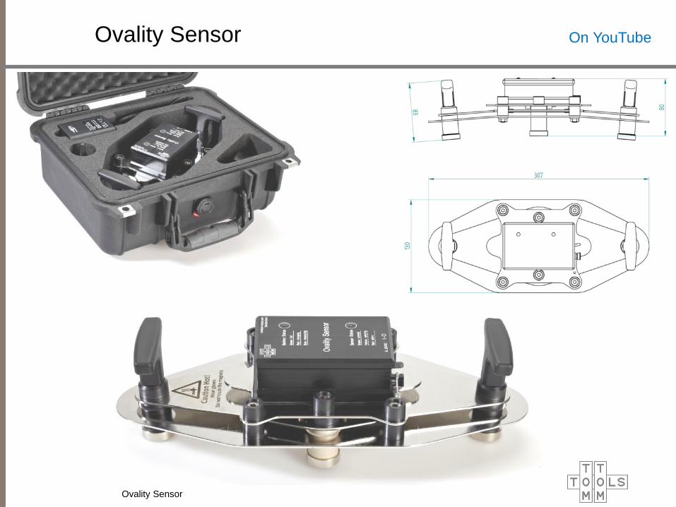
Ovality Sensor
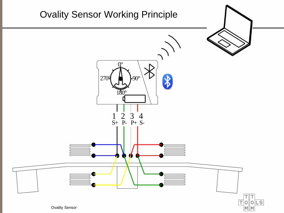
Ovality Sensor Working Principle
1 2 3 4S+ P- P+ S-
0°
90°
180°
270°
Ovality Sensor

Ovality Sensor
The Ovality Sensor is a
measurement tool for rotary kilns,
which measures the changes of the
roundness / curvature in the kiln
shell during operation.
This elastic deformation is called
Ovality and is primarily present in
the area of a kiln tire.
The measurement gives accurate
information about the degree of
mechanical loads in the refractory /
kiln shell and allows defining the
countermeasures in advance to
increase the lifetime of the kiln
components.
Ovality Sensor
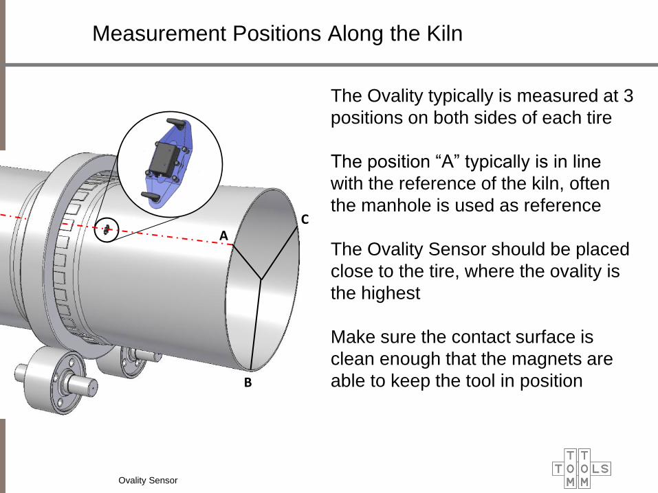
Measurement Positions Along the Kiln
B
A C
The Ovality typically is measured at 3
positions on both sides of each tire
The position “A” typically is in line
with the reference of the kiln, often
the manhole is used as reference
The Ovality Sensor should be placed
close to the tire, where the ovality is
the highest
Make sure the contact surface is
clean enough that the magnets are
able to keep the tool in position
Ovality Sensor

Measurement Studio / Ovality
Main Function
Buttons
Measurement
Results
Radar Chart
Kiln Overview
Ovality Sensor

Correct Shimming of the Tire is the Key
Too thick shims can lock the
tire Shell constriction
Too thin shims increase the
ovality Brick failures
Ovality Sensor
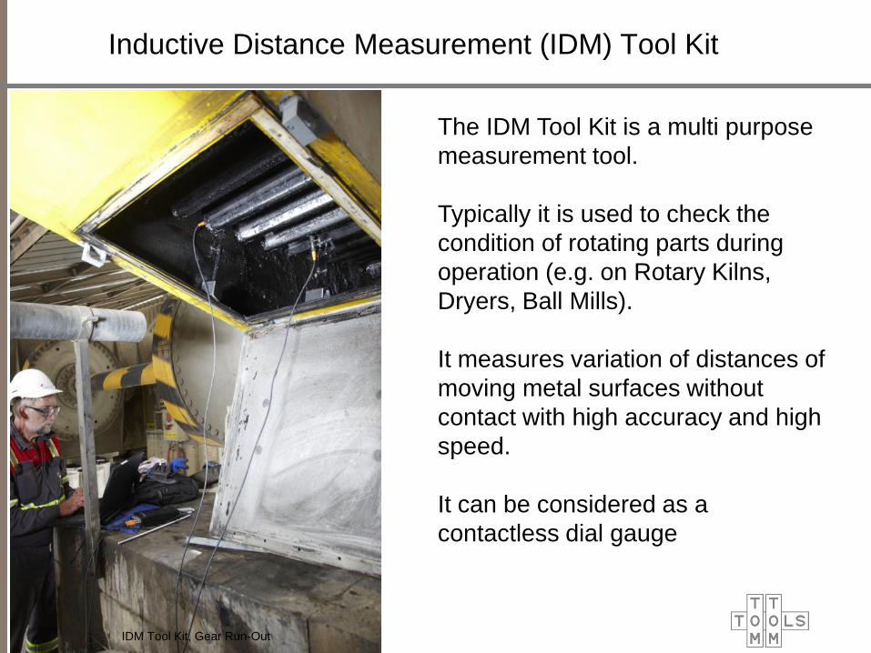
Inductive Distance Measurement (IDM) Tool Kit
The IDM Tool Kit is a multi purpose
measurement tool.
Typically it is used to check the
condition of rotating parts during
operation (e.g. on Rotary Kilns,
Dryers, Ball Mills).
It measures variation of distances of
moving metal surfaces without
contact with high accuracy and high
speed.
It can be considered as a
contactless dial gauge
IDM Tool Kit, Gear Run-Out
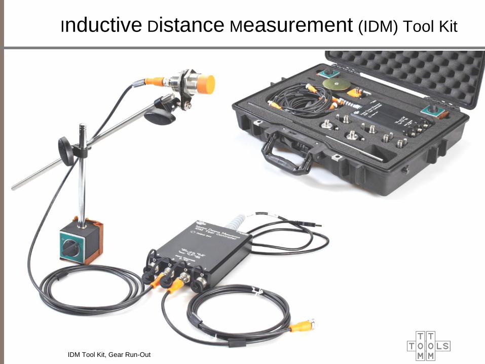
Inductive Distance Measurement (IDM) Tool Kit
IDM Tool Kit, Gear Run-Out
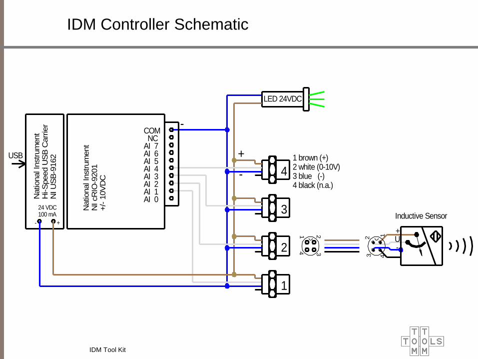
IDM Controller Schematic
LED 24VDC
1 brown (+)2 white (0-10V)3 blue (-)4 black (n.a.)
USB
-
-
+
2
3
4
1
AI 0AI 1AI 2AI 3AI 4AI 5AI 6AI 7 NCCOM
National In
str
um
ent
NI cR
IO-9
201
+/-
10V
DC
National In
str
um
ent
Hi-S
peed U
SB
Carr
ier
NI U
SB
-9162
24 VDC100 mA
- +
1 2
4 3
+
-U
Inductive Sensor
2 1
3 4
IDM Tool Kit
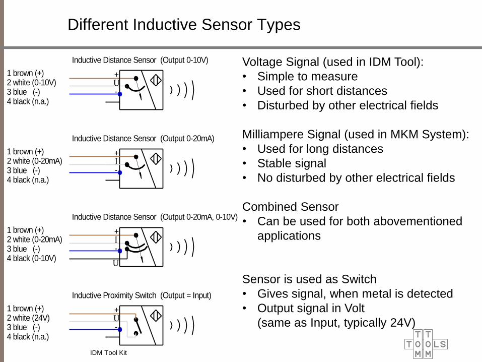
Different Inductive Sensor Types
Voltage Signal (used in IDM Tool):
• Simple to measure
• Used for short distances
• Disturbed by other electrical fields
Milliampere Signal (used in MKM System):
• Used for long distances
• Stable signal
• No disturbed by other electrical fields
Combined Sensor
• Can be used for both abovementioned
applications
Sensor is used as Switch
• Gives signal, when metal is detected
• Output signal in Volt
(same as Input, typically 24V)
1 brown (+)2 white (0-10V)3 blue (-)4 black (n.a.)
1 brown (+)2 white (0-20mA)3 blue (-)4 black (n.a.)
1 brown (+)2 white (0-20mA)3 blue (-)4 black (0-10V)
+
-U
Inductive Distance Sensor (Output 0-10V)
+
-I
Inductive Distance Sensor (Output 0-20mA)
+
-
U
Inductive Distance Sensor (Output 0-20mA, 0-10V)
1 brown (+)2 white (24V)3 blue (-)4 black (n.a.)
+
-U
Inductive Proximity Switch (Output = Input)
I
IDM Tool Kit
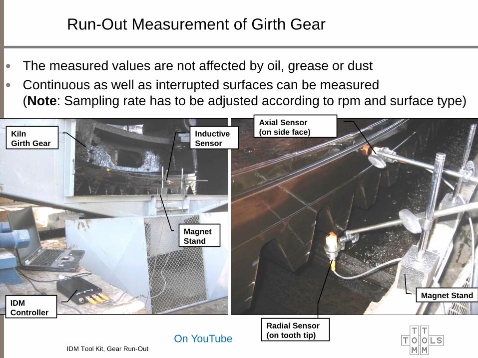
Run-Out Measurement of Girth Gear
Radial Sensor
(on tooth tip)
Axial Sensor
(on side face)
Magnet Stand
Kiln
Girth Gear
Inductive
Sensor
Magnet
Stand
IDM
Controller
On YouTube
• The measured values are not affected by oil, grease or dust
• Continuous as well as interrupted surfaces can be measured
(Note: Sampling rate has to be adjusted according to rpm and surface type)
IDM Tool Kit, Gear Run-Out
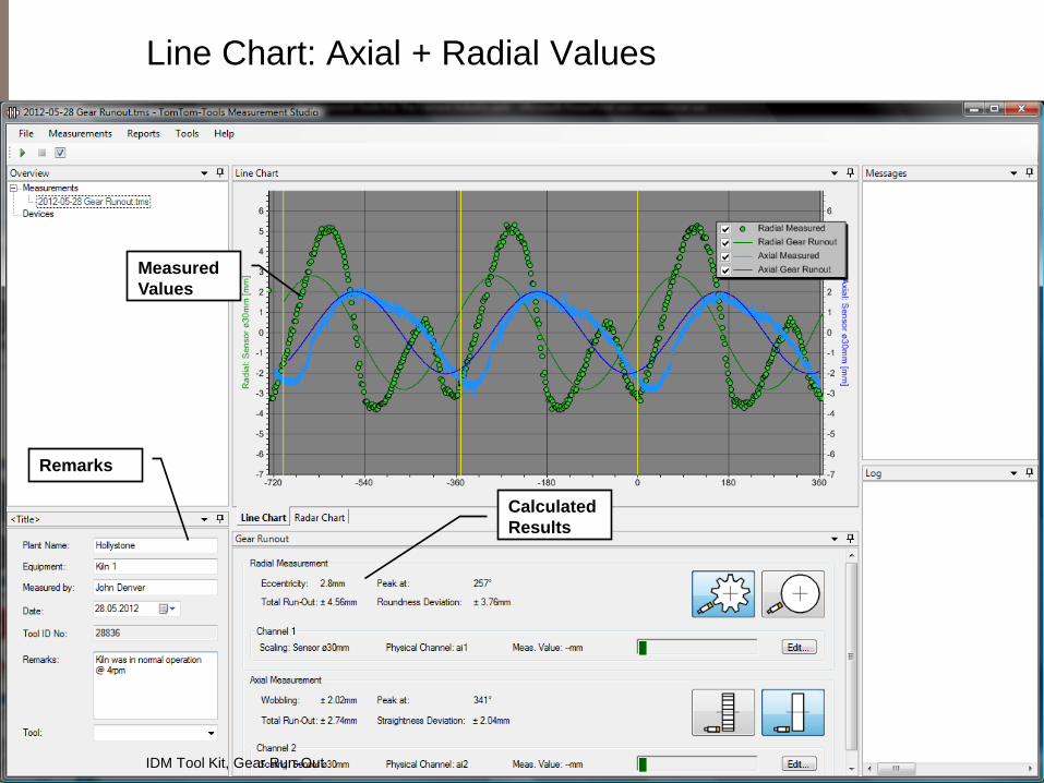
Line Chart: Axial + Radial Values
Measured
Values
Calculated
Results
Remarks
IDM Tool Kit, Gear Run-Out

Radar Chart: Radial Values
Measured
Values
Calculated
Results
Remarks
Ideal Circle
(with eccentricity)
Centre of
Girth Gear
Centre of
rotation
IDM Tool Kit, Gear Run-Out
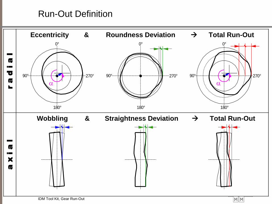
Run-Out Definition r a
d
i a
l
Eccentricity & Roundness Deviation Total Run-Out
a x i a
l
Wobbling & Straightness Deviation Total Run-Out
0°
270°90°
180°
0°
270°90°
180°
0°
270°90°
180°
a a
IDM Tool Kit, Gear Run-Out
IDM Tool Kit, Roller Shaft Bending
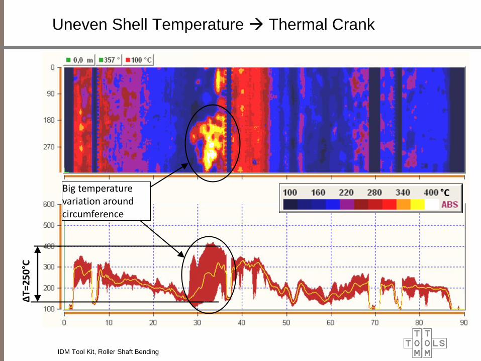
Uneven Shell Temperature Thermal Crank
Reduced Load
∆T=
25
0°C
°C Big temperature variation around circumference

Crank In Tire Area (up)
High Load No Load High Load
IDM Tool Kit, Roller Shaft Bending

Crank In Tire Area (down)
Reduced Load High Load Reduced Load
IDM Tool Kit, Roller Shaft Bending
Roller Shaft Bending
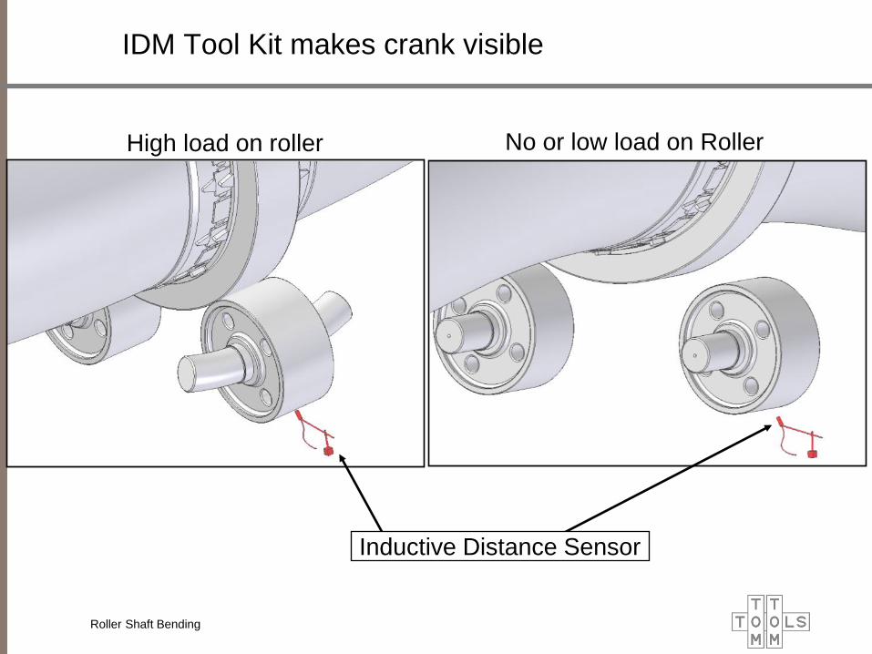
IDM Tool Kit makes crank visible
High load on roller No or low load on Roller
Inductive Distance Sensor

Roller Shaft Bending
•The roller shaft bending is measured via the radial displacement of the
roller surface (run-out)
•The sensor is located in the line of force under the roller
•It is measured during normal operation (no stop required)
•Only the variations are measured due to a crank, the static load due to
weight and possible alignment errors are not measured
Roller Bending Measurement
Inductive
Distance
Sensor

Thermal Crank (example 3 station kiln)
July 13: strong thermal crank high variation in roller shaft bending (±0.3mm)
July 15: no thermal crank low roller shaft bending value (±0.08mm)

Roller Shaft Bending Measurement
On YouTube
IDM Tool Kit, Roller Shaft Bending

Measurement Studio / Roller Shaft Bending
Roller Shaft
Bending Value
Position of
Crank
Roller Shaft
Bending Curve
Reference Line
(each kiln revolution)
IDM Tool Kit, Roller Shaft Bending

MKM-System (Mechanical Kiln Monitoring System)
Sensors for:
1. Roller Shaft Bending Measurement
2. Rotation Indication
3. Relative Movement of Tires
4. Axial Kiln Position
1
1 2
3
3
4
1 3
MKM System

2. Rotation
Indication
1. Roller Shaft Bending 3. Rel. Movement of Tire
4. Axial Kiln
Position
MKM-System (Mechanical Kiln Monitoring System)
MKM System
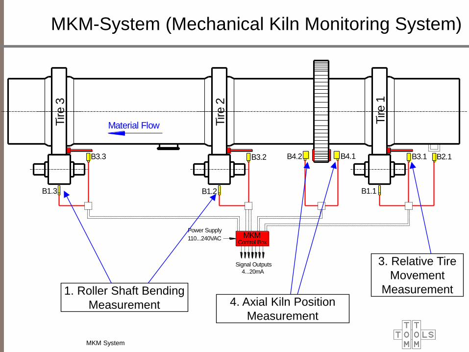
Material FlowTire 3
Tire 2
Tire 1
MKMControl Box
110...240VAC
Power Supply
4...20mA
Signal Outputs
B1.3 B1.2 B1.1
B3.3 B3.2 B3.1 B2.1B4.2 B4.1
4. Axial Kiln Position
Measurement
1. Roller Shaft Bending
Measurement
3. Relative Tire
Movement
Measurement
MKM-System (Mechanical Kiln Monitoring System)
MKM System

MKM Sensor Installation
Axial Kiln Position Sensor Relative Tire Movement Sensor
Roller Shaft Bending
Sensor
Kiln Speed
Sensor Axial Kiln Position Sensor
MKM System

MKM Controller / Data Logger
Data Logger
(DALOG 376)
Power supply
100…240VAC 24VDC
SD Card
Reader
LED Terminal Block
for Sensor and Output Signals
Terminal Block
Sensors Power Supply
MKM System
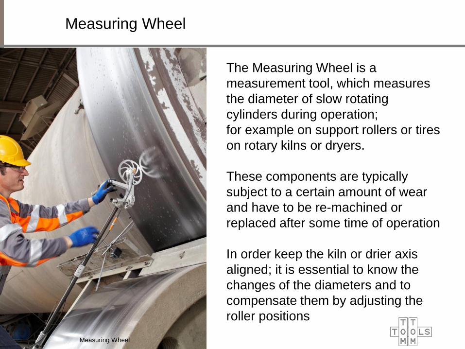
The Measuring Wheel is a
measurement tool, which measures
the diameter of slow rotating
cylinders during operation;
for example on support rollers or tires
on rotary kilns or dryers.
These components are typically
subject to a certain amount of wear
and have to be re-machined or
replaced after some time of operation
In order keep the kiln or drier axis
aligned; it is essential to know the
changes of the diameters and to
compensate them by adjusting the
roller positions
Measuring Wheel
Measuring Wheel

Measuring Wheel
Measuring Wheel

Measuring Wheel Schematic
Magnetic
Switch Flag
Measuring Wheel
with Encoder
Wheel
Controller
Light
Converter
Spring Loaded
Wheel Suspension
Light Barrier Sensor
(heat resistant 180°C)
Diameter
to measure
Measuring Wheel
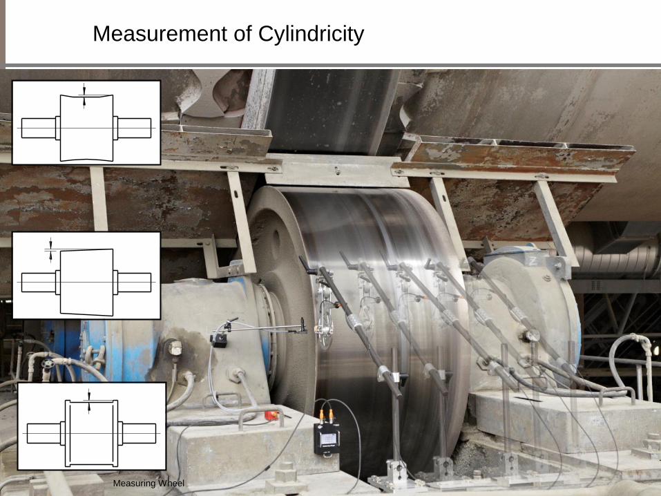
Measurement of Cylindricity
Measuring Wheel
Rotary Inclinometer
Rotary Inclinometer
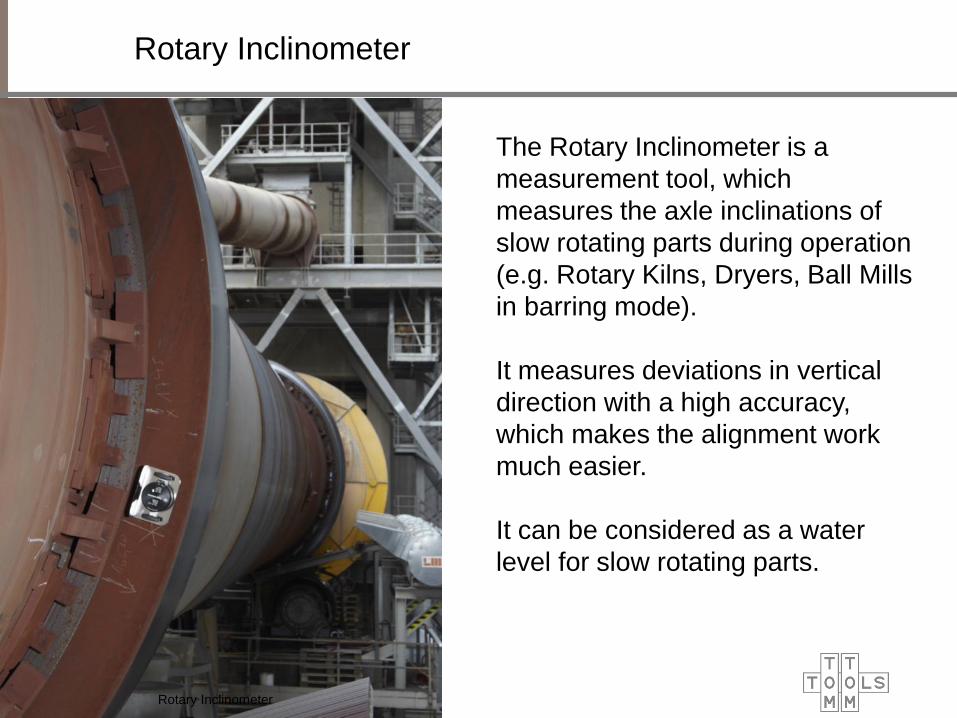
The Rotary Inclinometer is a
measurement tool, which
measures the axle inclinations of
slow rotating parts during operation
(e.g. Rotary Kilns, Dryers, Ball Mills
in barring mode).
It measures deviations in vertical
direction with a high accuracy,
which makes the alignment work
much easier.
It can be considered as a water
level for slow rotating parts.

Rotary Inclinometer
Rotary Inclinometer
Inclinometer with heat shield
to measure hot kiln tires Inclinometer with shaft adapter
to measure support rollers
at the shaft center

Rotary Inclinometer Schematic
Rotary Inclinometer
Rechargeable Li-Ion Battery
Circuit Board
Status LED
Linear Motion Module Y
Linear Motion Module X
Rotation Sensor
Gimbal-mounted Inclination Sensor
(-10°…+10°)
Magnet
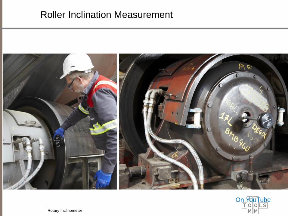
Roller Inclination Measurement
Rotary Inclinometer
On YouTube
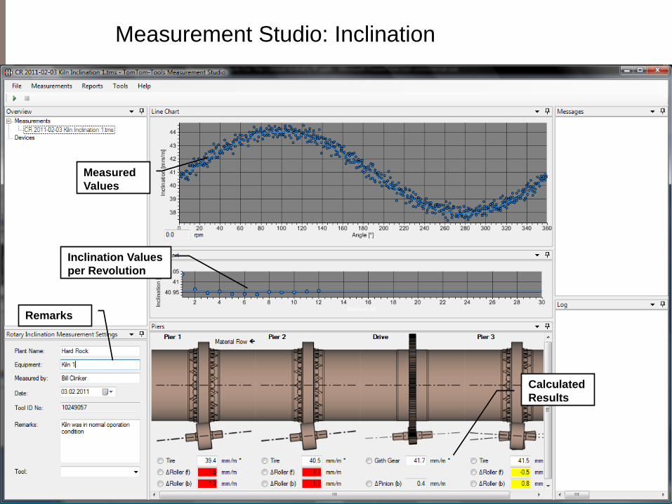
Measurement Studio: Inclination
Measured
Values
Calculated
Results
Remarks
Inclination Values
per Revolution
Kiln Shell Laser
Kiln Shell Laser
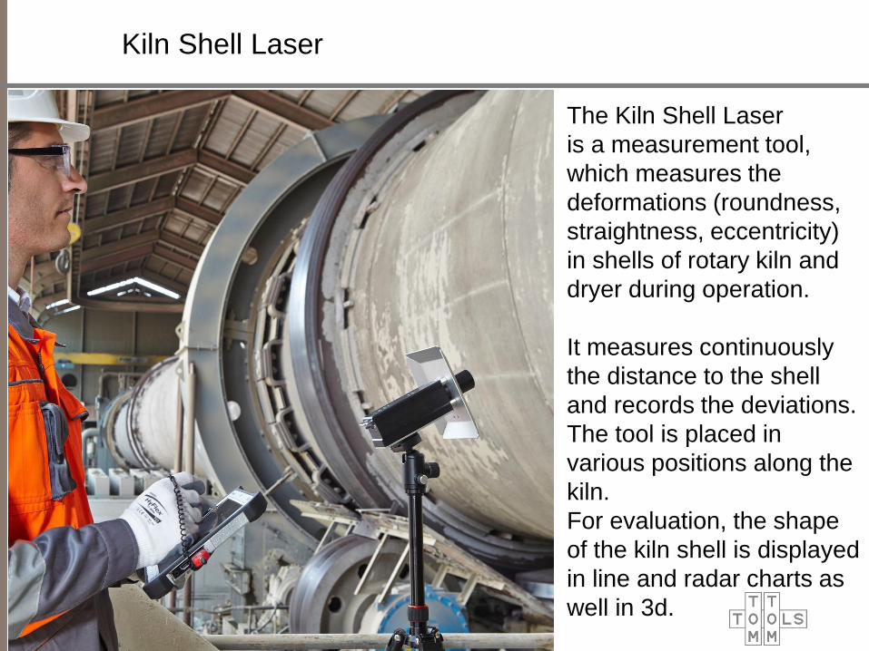
The Kiln Shell Laser
is a measurement tool,
which measures the
deformations (roundness,
straightness, eccentricity)
in shells of rotary kiln and
dryer during operation.
It measures continuously
the distance to the shell
and records the deviations.
The tool is placed in
various positions along the
kiln.
For evaluation, the shape
of the kiln shell is displayed
in line and radar charts as
well in 3d.

Kiln Shell Laser
Kiln Shell Laser
Kiln Shell Laser
on Tripod
Kiln Shell Laser
in transport case
Kiln Shell Laser
on G-Clamp
Rotation Trigger

Kiln Shell Laser
placed in various positions along the kiln
Kiln Shell Laser
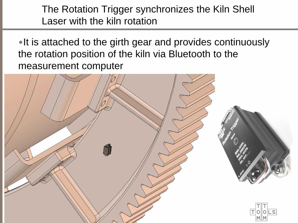
The Rotation Trigger synchronizes the Kiln Shell
Laser with the kiln rotation
•It is attached to the girth gear and provides continuously
the rotation position of the kiln via Bluetooth to the
measurement computer

Kiln Shell Laser in the Measurement Studio
offers different display options for evaluation
Kiln Shell Laser

Telescopic Contact Thermometer
•To measure the shaft temperature of the support rollers
•It helps to evaluate the condition of the bearings and the
thrust load
•The telescopic handle makes it easy to reach the roller
shaft
•It is much more precise than pyrometers and not affected
by the oil film