Mechanical Collapse Testing on Aluminum ... - Ship · PDF fileMechanical Collapse Testing on...
17
Mechanical Collapse Testing on Aluminum Stiffened Plate Structures for Marine Applications Jeom Kee Paik 1) , Celine Andrieu 2) , and H. Paul Cojeen 3) 1) Pusan National University, Korea, 2) Alcan Marine, France, 3) U.S. Coast Guard, USA Abstract The present paper is a summary of the R&D results obtained through SSC SR-1446 project sponsored by Ship Structure Committee together with Alcan Marine, France. It is recognized that the use of ultimate limit state (ULS) design method in addition to more conventional structural design standards will help make possible to move high speed vessels to open ocean transiting of very large high speed vessels, which is what the US Navy is certainly trying to do. The aim of the project is to investigate the collapse characteristics of aluminum stiffened plate structures used for marine applications by mechanical testing, together with nonlinear FEA. Fabrication related initial imperfections significantly affect the ULS behavior, and thus it is of vital importance to identify the features of initial imperfections prior to ULS computations. In the present study, statistical database of fabrication related initial imperfections on welded aluminum stiffened plate structures is also developed. The database and insights developed will be very useful for design and building of welded aluminum high-speed ocean-going vessel structures. Keywords Aluminum stiffened plate structures; High-speed ocean- going vessels; Ultimate limit state design; Mechanical collapse testing; Fabrication related initial imperfections; Nonlinear finite element analysis. Introduction The use of high strength aluminum alloys in shipbuilding provides many benefits but also presents many challenges. The benefits of using aluminum versus steel include lighter weight, which helps increase cargo capacity and/or reduce power requirements, excellent corrosion resistance and low maintenance. Challenges include reduced stiffness causing greater sensitivity to deformation, buckling, and plastic collapse and different welding practices. The benefits noted above are now well recognized, particularly for the design and construction of war ships, littoral surface crafts, and littoral combat ships as well as fast passenger ships. The size of such ships is increasing, causing various related design challenges compared to vessels with shorter length. In addition to aluminum alloys being less stiff than mild steel, no refined ultimate limit state (ULS) design methods involving local and overall ULS assessment exist unlike steel structures where the necessary information is plentiful. The use of ULS design method in addition to more conventional structural design standards will be able to help design and build very large ocean-going aluminum high speed vessel structures. The present paper is a summary of the R&D results obtained through SSC SR-1446 project sponsored by Ship Structure Committee together with Alcan Marine, France. Buckling collapse characteristics of welded aluminum stiffened plate structures were investigated by mechanical testing on a total of 78 single- and multi-bay prototype structures, which are full scale equivalent to subs-structures of an 80m long aluminum high speed vessel structure. Welding induced initial imperfections significantly affect the ULS behavior, and it is thus of vital importance to identify the features of initial imperfections prior to the ULS computations and design. In this regard, the statistics of welding induced initial imperfections on the prototype structures are measured and analyzed. The buckling collapse testing is undertaken until and after the ULS is reached. Nonlinear FEA solutions are also obtained for the prototype structures. Based on the experimental and numerical results, closed-form ULS formulae are developed. In the past, useful studies on mechanical collapse testing of welded aluminum structures have of course been undertaken. In the early 1980s, a series of 76 aluminum un-stiffened plate collapse tests were carried out by Mofflin (1983) and Mofflin & Dwight (1984) at the University of Cambridge, UK; and these are regarded as perhaps one of the largest and most relevant test programs for the collapse strength of aluminum plating (un-stiffened plates) until now. After TIG (tungsten inert gas) welding in the longitudinal direction and MIG (metal inert gas) welding in the transverse direction, weld induced initial distortions and residual stresses were measured and their influences on the plate collapse behavior were studied on two of the most 10th International Symposium on Practical Design of Ships and Other Floating Structures Houston, Texas, United States of America © 2007 American Bureau of Shipping
Transcript of Mechanical Collapse Testing on Aluminum ... - Ship · PDF fileMechanical Collapse Testing on...
Mechanical Collapse Testing on Aluminum StiffenedPlate Structures for Marine Applications
Jeom Kee Paik1), Celine Andrieu2), and H. Paul Cojeen3)
1) Pusan National University, Korea, 2) Alcan Marine, France, 3) U.S. Coast Guard, USA
Abstract
The present paper is a summary of the R&D resultsobtained through SSC SR-1446 project sponsored byShip Structure Committee together with Alcan Marine,France. It is recognized that the use of ultimate limitstate (ULS) design method in addition to moreconventional structural design standards will help makepossible to move high speed vessels to open oceantransiting of very large high speed vessels, which iswhat the US Navy is certainly trying to do.
The aim of the project is to investigate the collapsecharacteristics of aluminum stiffened plate structuresused for marine applications by mechanical testing,together with nonlinear FEA. Fabrication related initialimperfections significantly affect the ULS behavior, andthus it is of vital importance to identify the features ofinitial imperfections prior to ULS computations. In thepresent study, statistical database of fabrication relatedinitial imperfections on welded aluminum stiffenedplate structures is also developed. The database andinsights developed will be very useful for design andbuilding of welded aluminum high-speed ocean-goingvessel structures.
Keywords
Aluminum stiffened plate structures; High-speed ocean-going vessels; Ultimate limit state design; Mechanicalcollapse testing; Fabrication related initialimperfections; Nonlinear finite element analysis.
Introduction
The use of high strength aluminum alloys inshipbuilding provides many benefits but also presentsmany challenges. The benefits of using aluminumversus steel include lighter weight, which helps increasecargo capacity and/or reduce power requirements,excellent corrosion resistance and low maintenance.Challenges include reduced stiffness causing greatersensitivity to deformation, buckling, and plastic collapseand different welding practices.
The benefits noted above are now well recognized,particularly for the design and construction of war ships,littoral surface crafts, and littoral combat ships as well
as fast passenger ships. The size of such ships isincreasing, causing various related design challengescompared to vessels with shorter length. In addition toaluminum alloys being less stiff than mild steel, norefined ultimate limit state (ULS) design methodsinvolving local and overall ULS assessment exist unlikesteel structures where the necessary information isplentiful. The use of ULS design method in addition tomore conventional structural design standards will beable to help design and build very large ocean-goingaluminum high speed vessel structures.
The present paper is a summary of the R&D resultsobtained through SSC SR-1446 project sponsored byShip Structure Committee together with Alcan Marine,France. Buckling collapse characteristics of weldedaluminum stiffened plate structures were investigated bymechanical testing on a total of 78 single- and multi-bayprototype structures, which are full scale equivalent tosubs-structures of an 80m long aluminum high speedvessel structure. Welding induced initial imperfectionssignificantly affect the ULS behavior, and it is thus ofvital importance to identify the features of initialimperfections prior to the ULS computations and design.In this regard, the statistics of welding induced initialimperfections on the prototype structures are measuredand analyzed. The buckling collapse testing isundertaken until and after the ULS is reached.Nonlinear FEA solutions are also obtained for theprototype structures. Based on the experimental andnumerical results, closed-form ULS formulae aredeveloped.
In the past, useful studies on mechanical collapsetesting of welded aluminum structures have of coursebeen undertaken. In the early 1980s, a series of 76aluminum un-stiffened plate collapse tests were carriedout by Mofflin (1983) and Mofflin & Dwight (1984) atthe University of Cambridge, UK; and these areregarded as perhaps one of the largest and most relevanttest programs for the collapse strength of aluminumplating (un-stiffened plates) until now. After TIG(tungsten inert gas) welding in the longitudinal directionand MIG (metal inert gas) welding in the transversedirection, weld induced initial distortions and residualstresses were measured and their influences on the platecollapse behavior were studied on two of the most
10th International Symposium on Practical Design of Ships and Other Floating StructuresHouston, Texas, United States of America© 2007 American Bureau of Shipping
common aluminum alloys used for the construction ofhigh speed vessels, i.e., 5083 and 6082 alloys.
In the late 1980s, Clarke & Swan (1985) and Clarke(1987) at the Admiralty Research Establishment (ARE),UK carried out the buckling collapse testing on a totalof five aluminum stiffened plate structures. This wasone of the earliest collapse test programs to use ship-shaped aluminum stiffened plate structures using full-scale prototype models of all-welded construction withmultiple frame bays. All material of the test structureswas equivalent to 5083 aluminum alloy.
Over a decade after the ARE tests, several collapsetest programs on aluminum stiffened plate structuresconstructed by welding were carried out together withvarious surveys of weld induced initial imperfections.These include Hopperstad et al. (1998, 1999), Tanaka &Matsuoka (1997), Matsuoka et al. (1999), Zha et al.(2000), Zha & Moan (2001, 2003) and Aalberg et al.(2001). The material of most test structures was 5083aluminum alloy for plating and 6082 aluminum alloy forstiffeners.
Except perhaps for those by Tanaka & Matsuoka(1997) and Matsuoka et al. (1999) which were full-scaleprototype models with multiple frame bays, most ofthese test structures were small scale models composedof a single stiffener with attached plating or a thin-walled cruciform structure. Although the nature andextent of test structures were somewhat limited, thesetest results were still very useful in studying thestatistics of weld induced initial imperfections as well asthe compressive collapse strength characteristicsthemselves.
Even in light of the existing excellent research resultson the weld induced initial imperfections and ultimatestrength of aluminum structures noted above, morestudies are certainly required, because a systematicsurvey of the initial imperfection and buckling collapsecharacteristics is very lacking for a variety of aluminumalloy types and structural dimensions typical of ship-shaped full-scale prototype structures considering therecent trends in the application of aluminum marinestructures.
A significant motive for initiating the presentresearch project was to contribute to resolving the issuenoted above to a good degree, by developing relevantdesign database on fabrication related initialimperfections and ultimate strength of weldedaluminum stiffened plate structures for marineapplications.
Design and fabrication of test structures
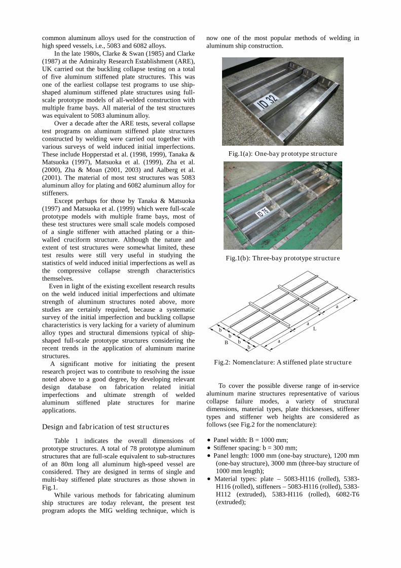
Table 1 indicates the overall dimensions ofprototype structures. A total of 78 prototype aluminumstructures that are full-scale equivalent to sub-structuresof an 80m long all aluminum high-speed vessel areconsidered. They are designed in terms of single andmulti-bay stiffened plate structures as those shown inFig.1.
While various methods for fabricating aluminumship structures are today relevant, the present testprogram adopts the MIG welding technique, which is
now one of the most popular methods of welding inaluminum ship construction.
Fig.1(a): One-bay prototype structure
Fig.1(b): Three-bay prototype structure
bb
bb
B a
a
a
L
Fig.2: Nomenclature: A stiffened plate structure
To cover the possible diverse range of in-servicealuminum marine structures representative of variouscollapse failure modes, a variety of structuraldimensions, material types, plate thicknesses, stiffenertypes and stiffener web heights are considered asfollows (see Fig.2 for the nomenclature):
Panel width: B = 1000 mm; Stiffener spacing: b = 300 mm; Panel length: 1000 mm (one-bay structure), 1200 mm
(one-bay structure), 3000 mm (three-bay structure of1000 mm length);
Material types: plate – 5083-H116 (rolled), 5383-H116 (rolled), stiffeners – 5083-H116 (rolled), 5383-H112 (extruded), 5383-H116 (rolled), 6082-T6(extruded);
Thickness: plate – 5 mm, 6 mm, 8 mm, stiffeners – 4mm, 5 mm, 6 mm, 8 mm;
Stiffener types: flat bar, built-up T-bar, extruded T-bar;
Stiffener web height: 60 mm, 70 mm, 80 mm, 90 mm,100 mm, 120 mm, 140 mm.
Table 2 indicates the minimum values ofmechanical properties of aluminum alloys used forbuilding the prototype structures.
Statistics of weld induced initial imperfections
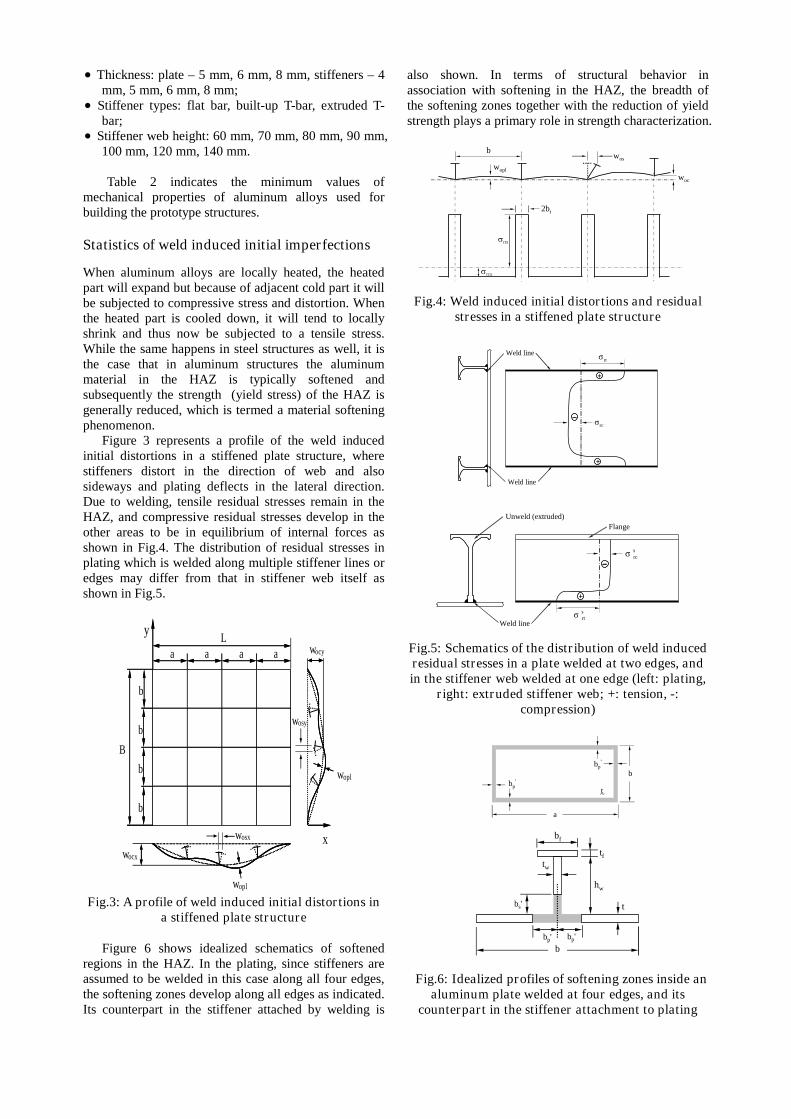
When aluminum alloys are locally heated, the heatedpart will expand but because of adjacent cold part it willbe subjected to compressive stress and distortion. Whenthe heated part is cooled down, it will tend to locallyshrink and thus now be subjected to a tensile stress.While the same happens in steel structures as well, it isthe case that in aluminum structures the aluminummaterial in the HAZ is typically softened andsubsequently the strength (yield stress) of the HAZ isgenerally reduced, which is termed a material softeningphenomenon.
Figure 3 represents a profile of the weld inducedinitial distortions in a stiffened plate structure, wherestiffeners distort in the direction of web and alsosideways and plating deflects in the lateral direction.Due to welding, tensile residual stresses remain in theHAZ, and compressive residual stresses develop in theother areas to be in equilibrium of internal forces asshown in Fig.4. The distribution of residual stresses inplating which is welded along multiple stiffener lines oredges may differ from that in stiffener web itself asshown in Fig.5.
B
Ly
xwocx
wopl
wopl
wocy
b
b
b
b
a aaa
wosx
wosy
Fig.3: A profile of weld induced initial distortions ina stiffened plate structure
Figure 6 shows idealized schematics of softenedregions in the HAZ. In the plating, since stiffeners areassumed to be welded in this case along all four edges,the softening zones develop along all edges as indicated.Its counterpart in the stiffener attached by welding is
also shown. In terms of structural behavior inassociation with softening in the HAZ, the breadth ofthe softening zones together with the reduction of yieldstrength plays a primary role in strength characterization.
rcx
b
rtx
wopl
2bt
wos
woc
Fig.4: Weld induced initial distortions and residualstresses in a stiffened plate structure
++
++
Weld line
Weld linertσ
rcσ
++
Weld line
Unweld (extruded)
Flange
srcσ
srtσ
Fig.5: Schematics of the distribution of weld inducedresidual stresses in a plate welded at two edges, andin the stiffener web welded at one edge (left: plating,
right: extruded stiffener web; +: tension, -:compression)
b
a
bp'
t~
bp'
b
bs'
bf
tf
hw
t
tw
bp' bp'
Fig.6: Idealized profiles of softening zones inside analuminum plate welded at four edges, and its
counterpart in the stiffener attachment to plating
While weld induced initial imperfections describedabove should be minimized by application of properwelding procedures and fabrication methods, it isnevertheless important to realize that their levels inspecific cases can have a remarkable influence on thestrength and stiffness of the structures. Hence theirlevels must be dealt with as parameters of influence inthe analysis of load-carrying capacity. This means thatsuch initial imperfection parameters must be properlydetermined in advance and accounted for in the designprocess including reliability analyses and codecalibrations.
For aluminum stiffened plate structures constructedby welding, the following six types of initialimperfections will generally be pertinent, namely
Initial distortion of plating between stiffeners; Column type initial distortion of stiffener; Sideways initial distortion of stiffener; Residual stresses of plating between stiffeners; Residual stresses of stiffener web; Softening in the HAZ in terms of reduction of the
HAZ material yield stress and breadth of softenedzone.
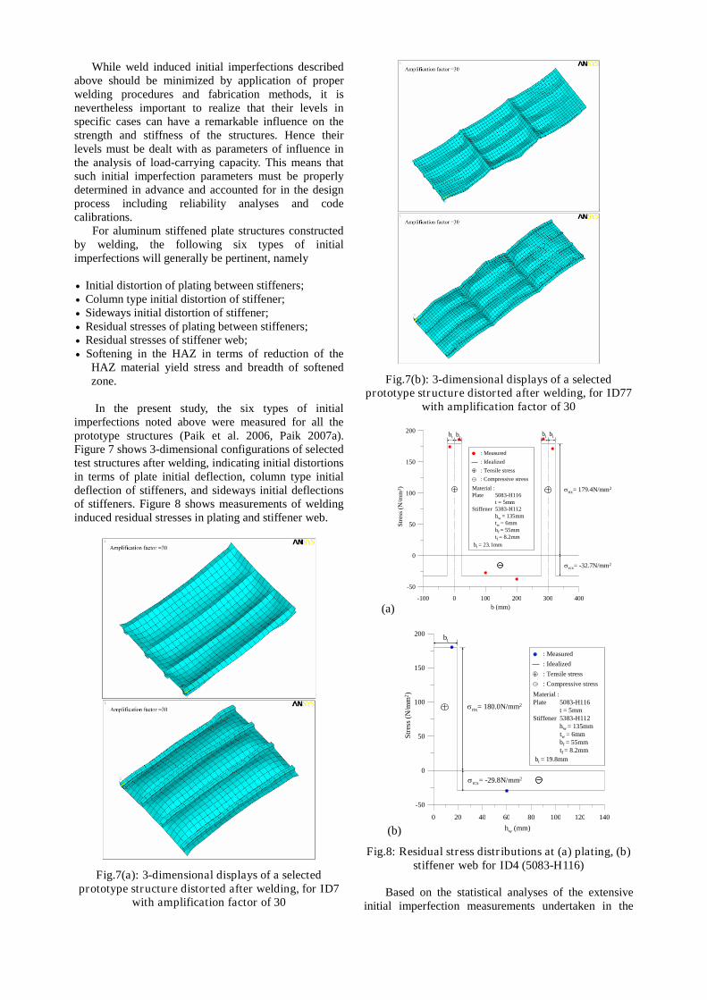
In the present study, the six types of initialimperfections noted above were measured for all theprototype structures (Paik et al. 2006, Paik 2007a).Figure 7 shows 3-dimensional configurations of selectedtest structures after welding, indicating initial distortionsin terms of plate initial deflection, column type initialdeflection of stiffeners, and sideways initial deflectionsof stiffeners. Figure 8 shows measurements of weldinginduced residual stresses in plating and stiffener web.
Fig.7(a): 3-dimensional displays of a selectedprototype structure distorted after welding, for ID7
with amplification factor of 30
Fig.7(b): 3-dimensional displays of a selectedprototype structure distorted after welding, for ID77
with amplification factor of 30
(a)-100 0 100 200 300 400
-50
0
50
100
150
200
: Idealized
: Measured
: Compressive stress
bt = 23.1mm
Material :Plate 5083-H116
t = 5mmStiffener 5383-H112
hw = 135mmtw = 6mmbf = 55mmtf = 8.2mm
: Tensile stress
Str
ess
(N/m
m2 ) rtx= 179.4N/mm2
rcx= -32.7N/mm2
bt btbt bt
b (mm)
(b)
0 20 40 60 80 100 120 140
-50
0
50
100
150
200
: Idealized
: Measured
: Compressive stress
bt = 19.8mm
Material :Plate 5083-H116
t = 5mmStiffener 5383-H112
hw = 135mmtw = 6mmbf = 55mmtf = 8.2mm
: Tensile stress
hw (mm)
Str
ess
(N/m
m2)
bt
rtx= 180.0N/mm2
rcx= -29.8N/mm2
Fig.8: Residual stress distributions at (a) plating, (b)stiffener web for ID4 (5083-H116)
Based on the statistical analyses of the extensiveinitial imperfection measurements undertaken in the
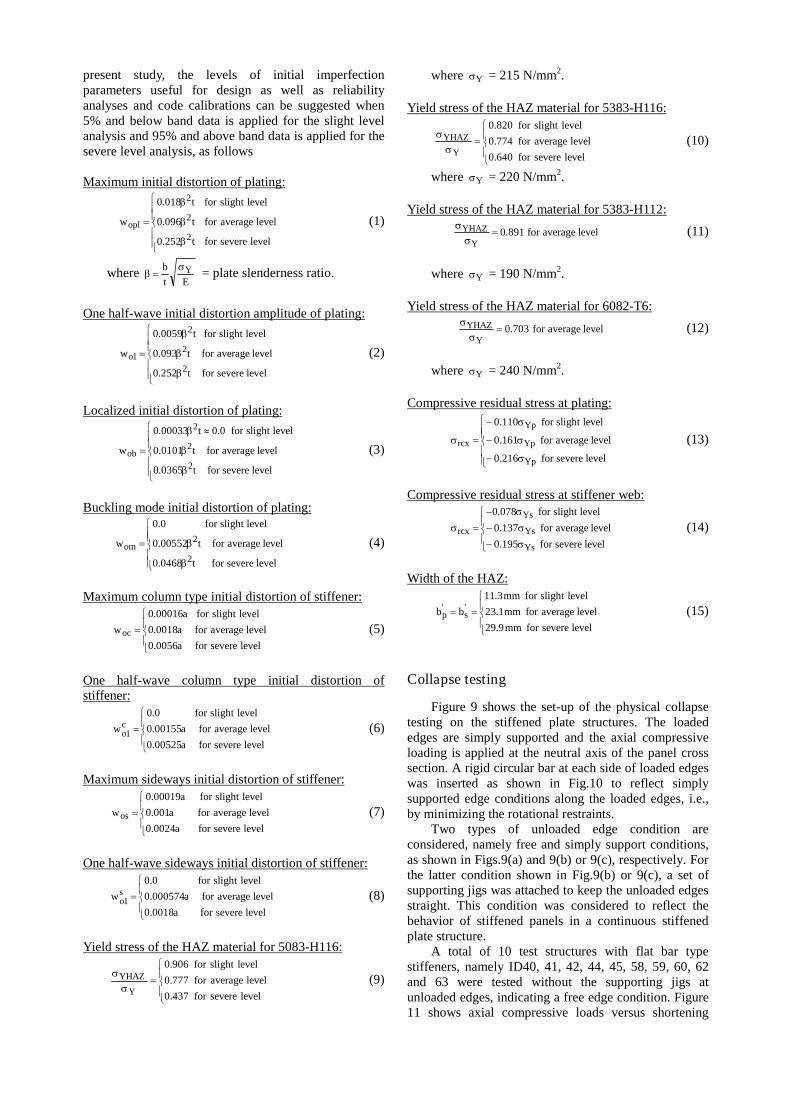
present study, the levels of initial imperfectionparameters useful for design as well as reliabilityanalyses and code calibrations can be suggested when5% and below band data is applied for the slight levelanalysis and 95% and above band data is applied for thesevere level analysis, as follows
Maximum initial distortion of plating:
levelseverefort252.0
levelaveragefort096.0
levelslightfort018.0
w
2
2
2
opl (1)
whereEt
b Y = plate slenderness ratio.
One half-wave initial distortion amplitude of plating:
levelseverefort252.0
levelaveragefort093.0
levelslightfort0059.0
w
2
2
2
1o (2)
Localized initial distortion of plating:
levelseverefort0365.0
levelaveragefort0101.0
levelslightfor0.0t00033.0
w
2
2
2
ob (3)
Buckling mode initial distortion of plating:
levelseverefort0468.0
levelaveragefort00552.0
levelslightfor0.0
w
2
2om (4)
Maximum column type initial distortion of stiffener:
levelseverefora0056.0
levelaveragefora0018.0
levelslightfora00016.0
woc (5)
One half-wave column type initial distortion ofstiffener:
levelseverefora00525.0
levelaveragefora00155.0
levelslightfor0.0
wc1o (6)
Maximum sideways initial distortion of stiffener:
levelseverefora0024.0
levelaveragefora001.0
levelslightfora00019.0
wos (7)
One half-wave sideways initial distortion of stiffener:
levelseverefora0018.0
levelaveragefora000574.0
levelslightfor0.0
ws1o (8)
Yield stress of the HAZ material for 5083-H116:
levelseverefor437.0
levelaveragefor777.0
levelslightfor906.0
Y
YHAZ (9)
where Y = 215 N/mm2.
Yield stress of the HAZ material for 5383-H116:
levelseverefor640.0
levelaveragefor774.0
levelslightfor820.0
Y
YHAZ (10)
where Y = 220 N/mm2.
Yield stress of the HAZ material for 5383-H112:
levelaveragefor891.0Y
YHAZ
(11)
where Y = 190 N/mm2.
Yield stress of the HAZ material for 6082-T6:
levelaveragefor703.0Y
YHAZ
(12)
where Y = 240 N/mm2.
Compressive residual stress at plating:
levelseverefor216.0
levelaveragefor161.0
levelslightfor110.0
Yp
Yp
Yp
rcx (13)
Compressive residual stress at stiffener web:
levelseverefor195.0
levelaveragefor137.0
levelslightfor078.0
Ys
Ys
Ys
rcx (14)
Width of the HAZ:
levelsevereformm9.29
levelaverageformm1.23
levelslightformm3.11
bb 's
'p (15)
Collapse testing
Figure 9 shows the set-up of the physical collapsetesting on the stiffened plate structures. The loadededges are simply supported and the axial compressiveloading is applied at the neutral axis of the panel crosssection. A rigid circular bar at each side of loaded edgeswas inserted as shown in Fig.10 to reflect simplysupported edge conditions along the loaded edges, i.e.,by minimizing the rotational restraints.
Two types of unloaded edge condition areconsidered, namely free and simply support conditions,as shown in Figs.9(a) and 9(b) or 9(c), respectively. Forthe latter condition shown in Fig.9(b) or 9(c), a set ofsupporting jigs was attached to keep the unloaded edgesstraight. This condition was considered to reflect thebehavior of stiffened panels in a continuous stiffenedplate structure.
A total of 10 test structures with flat bar typestiffeners, namely ID40, 41, 42, 44, 45, 58, 59, 60, 62and 63 were tested without the supporting jigs atunloaded edges, indicating a free edge condition. Figure11 shows axial compressive loads versus shortening
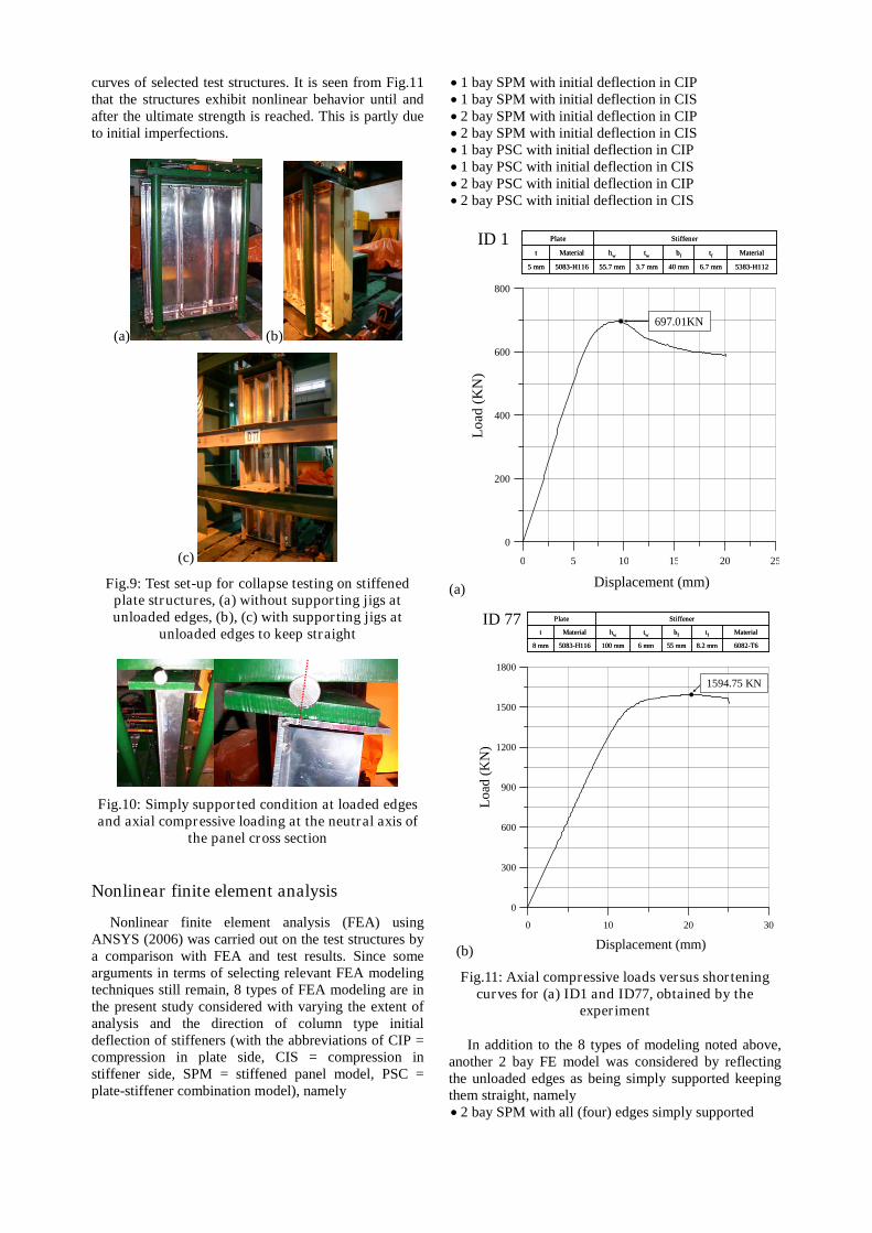
curves of selected test structures. It is seen from Fig.11that the structures exhibit nonlinear behavior until andafter the ultimate strength is reached. This is partly dueto initial imperfections.
(a) (b)
(c)
Fig.9: Test set-up for collapse testing on stiffenedplate structures, (a) without supporting jigs atunloaded edges, (b), (c) with supporting jigs at
unloaded edges to keep straight
Fig.10: Simply supported condition at loaded edgesand axial compressive loading at the neutral axis of
the panel cross section
Nonlinear finite element analysis
Nonlinear finite element analysis (FEA) usingANSYS (2006) was carried out on the test structures bya comparison with FEA and test results. Since somearguments in terms of selecting relevant FEA modelingtechniques still remain, 8 types of FEA modeling are inthe present study considered with varying the extent ofanalysis and the direction of column type initialdeflection of stiffeners (with the abbreviations of CIP =compression in plate side, CIS = compression instiffener side, SPM = stiffened panel model, PSC =plate-stiffener combination model), namely
1 bay SPM with initial deflection in CIP 1 bay SPM with initial deflection in CIS 2 bay SPM with initial deflection in CIP 2 bay SPM with initial deflection in CIS 1 bay PSC with initial deflection in CIP 1 bay PSC with initial deflection in CIS 2 bay PSC with initial deflection in CIP 2 bay PSC with initial deflection in CIS
(a)
0 5 10 15 20 25
0
200
400
600
800
Displacement (mm)
Lo
ad(K
N)
ID 1
5383-H1126.7 mm40 mm3.7 mm55.7 mm5083-H1165 mm
MaterialtfbftwhwMaterialt
StiffenerPlate
5383-H1126.7 mm40 mm3.7 mm55.7 mm5083-H1165 mm
MaterialtfbftwhwMaterialt
StiffenerPlate
697.01KN
(b)
0 10 20 30
0
300
600
900
1200
1500
1800
Displacement (mm)
Lo
ad(K
N)
ID 77
6082-T68.2 mm55 mm6 mm100 mm5083-H1168 mm
MaterialtfbftwhwMaterialt
StiffenerPlate
6082-T68.2 mm55 mm6 mm100 mm5083-H1168 mm
MaterialtfbftwhwMaterialt
StiffenerPlate
1594.75 KN
Fig.11: Axial compressive loads versus shorteningcurves for (a) ID1 and ID77, obtained by the
experiment
In addition to the 8 types of modeling noted above,another 2 bay FE model was considered by reflectingthe unloaded edges as being simply supported keepingthem straight, namely 2 bay SPM with all (four) edges simply supported
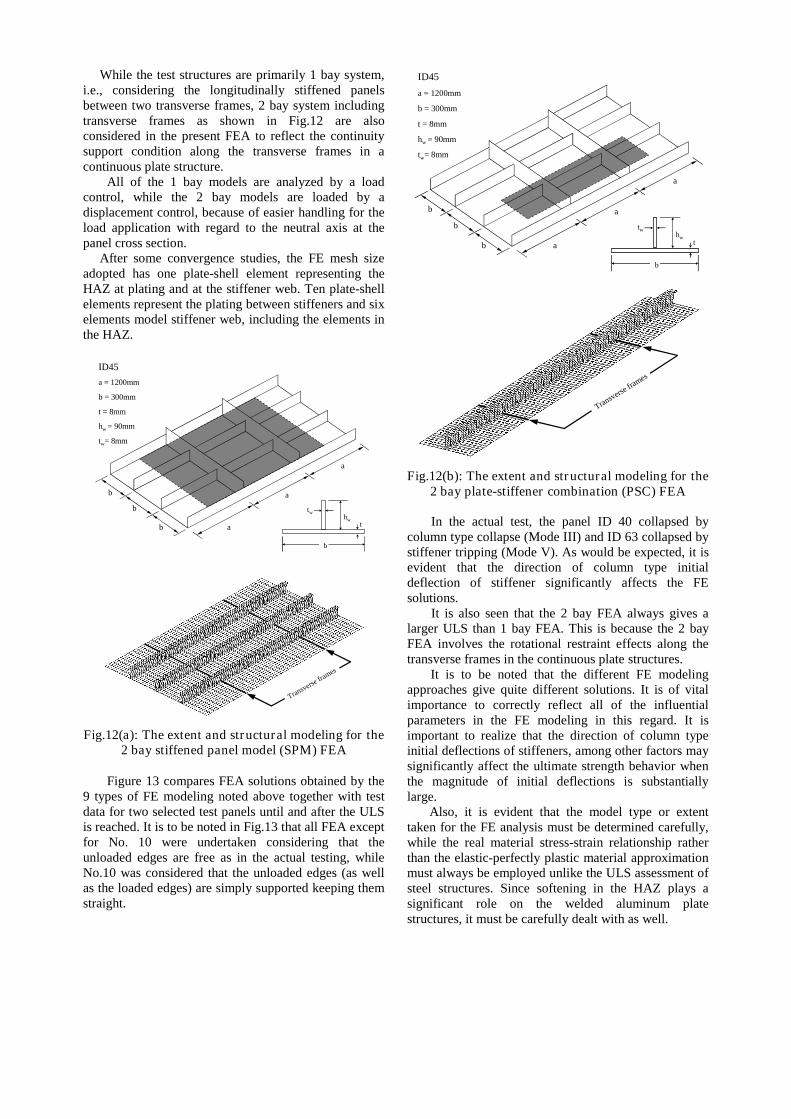
While the test structures are primarily 1 bay system,i.e., considering the longitudinally stiffened panelsbetween two transverse frames, 2 bay system includingtransverse frames as shown in Fig.12 are alsoconsidered in the present FEA to reflect the continuitysupport condition along the transverse frames in acontinuous plate structure.
All of the 1 bay models are analyzed by a loadcontrol, while the 2 bay models are loaded by adisplacement control, because of easier handling for theload application with regard to the neutral axis at thepanel cross section.
After some convergence studies, the FE mesh sizeadopted has one plate-shell element representing theHAZ at plating and at the stiffener web. Ten plate-shellelements represent the plating between stiffeners and sixelements model stiffener web, including the elements inthe HAZ.
b
hwt
tw
ID45
a = 1200mm
b = 300mm
t = 8mm
hw = 90mm
tw= 8mm
a
a
a
b
b
b
Transverse
frames
Fig.12(a): The extent and structural modeling for the2 bay stiffened panel model (SPM) FEA
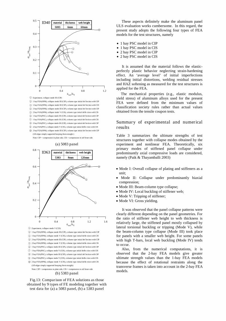
Figure 13 compares FEA solutions obtained by the9 types of FE modeling noted above together with testdata for two selected test panels until and after the ULSis reached. It is to be noted in Fig.13 that all FEA exceptfor No. 10 were undertaken considering that theunloaded edges are free as in the actual testing, whileNo.10 was considered that the unloaded edges (as wellas the loaded edges) are simply supported keeping themstraight.
a
a
a
b
b
b
b
hwt
tw
ID45
a = 1200mm
b = 300mm
t = 8mm
hw = 90mm
tw= 8mm
Transverse fra
mes
Fig.12(b): The extent and structural modeling for the2 bay plate-stiffener combination (PSC) FEA
In the actual test, the panel ID 40 collapsed bycolumn type collapse (Mode III) and ID 63 collapsed bystiffener tripping (Mode V). As would be expected, it isevident that the direction of column type initialdeflection of stiffener significantly affects the FEsolutions.
It is also seen that the 2 bay FEA always gives alarger ULS than 1 bay FEA. This is because the 2 bayFEA involves the rotational restraint effects along thetransverse frames in the continuous plate structures.
It is to be noted that the different FE modelingapproaches give quite different solutions. It is of vitalimportance to correctly reflect all of the influentialparameters in the FE modeling in this regard. It isimportant to realize that the direction of column typeinitial deflections of stiffeners, among other factors maysignificantly affect the ultimate strength behavior whenthe magnitude of initial deflections is substantiallylarge.
Also, it is evident that the model type or extenttaken for the FE analysis must be determined carefully,while the real material stress-strain relationship ratherthan the elastic-perfectly plastic material approximationmust always be employed unlike the ULS assessment ofsteel structures. Since softening in the HAZ plays asignificant role on the welded aluminum platestructures, it must be carefully dealt with as well.
0 0.4 0.8 1.2
0
0.1
0.2
0.3
0.4
0.5ID40
xav/Y
xav/
Yse
q6mm
thickness
5083 60mm
material web height
6mm
thickness
5083 60mm
material web height
Experiment, collapse mode III (CIP)
1 bay FEA(SPM), collapse mode III (CIP), column type initial def lection with CIP
1 bay FEA(SPM), collapse mode III (CIP), column type initial def lection with CIS
2 bay FEA(SPM), collapse mode III (CIP), column type initial def lection with CIP
2 bay FEA(SPM), collapse mode V (CIS), column type initial defle ction with CIS
1 bay FEA(PSC), collapse mode III (CIP), column type initial def lection with CIP
1 bay FEA(PSC), collapse mode III (CIP), column type initial def lection with CIS
2 bay FEA(PSC), collapse mode III (CIP), column type initial def lection with CIP
2 bay FEA(PSC), collapse mode V (CIS), column type initial defle ction with CIS
2 bay FEA(SPM), collapse mode III (CIP), column type initial def lection with CIP
(All edges simply supported keeping them straight )
Note: CIP = compression in plate side, CIS = compression in stif fener side
1
2
3
4
5
1
2
3
4
5
6
7
8
9
6
8
9
7
10
10
(a) 5083 panel
0 0.4 0.8 1.2 1.6
0
0.2
0.4
0.6
0.8ID63
8mm
thickness
5383 120mm
material web height
8mm
thickness
5383 120mm
material web height
1
2
3
4
5
8
7
9
6 10
xav/Y
Experiment, collapse mode V (CIS)
1 bay FEA(SPM), collapse mode III (CIP), column type initial def lection with CIP
1 bay FEA(SPM), collapse mode V (CIS), column type initial defle ction with CIS
2 bay FEA(SPM), collapse mode III (CIP), column type initial def lection with CIP
2 bay FEA(SPM), collapse mode V (CIS), column type initial defle ction with CIS
1 bay FEA(PSC), collapse mode III (CIP), column type initial def lection with CIP
1 bay FEA(PSC), collapse mode V (CIS), column type initial defle ction with CIS
2 bay FEA(PSC), collapse mode III (CIP), column type initial def lection with CIP
2 bay FEA(PSC), collapse mode V (CIS), column type initial defle ction with CIS
2 bay FEA(SPM), collapse mode V (CIS), column type initial defle ction with CIS
(All edges simply supported keeping them straight)
Note: CIP = compression in plate side, CIS = compression in stif fener side
1
2
3
4
5
6
7
8
9
10
xa
v/
Yse
q
(b) 5383 panel
Fig.13: Comparison of FEA solutions as thoseobtained by 9 types of FE modeling together with
test data for (a) a 5083 panel, (b) a 5383 panel
These aspects definitely make the aluminum panelULS evaluation works cumbersome. In this regard, thepresent study adopts the following four types of FEAmodels for the test structures, namely
1 bay PSC model in CIP 1 bay PSC model in CIS 2 bay PSC model in CIP 2 bay PSC model in CIS
It is assumed that the material follows the elastic-perfectly plastic behavior neglecting strain-hardeningeffect. An ‘average level’ of initial imperfectionsincluding initial distortions, welding residual stressesand HAZ softening as measured for the test structures isapplied for the FEA.
The mechanical properties (e.g., elastic modulus,yield stress) of aluminum alloys used for the presentFEA were defined from the minimum values ofclassification society rules rather than actual valuesobtained from the tensile coupon tests.
Summary of experimental and numericalresults
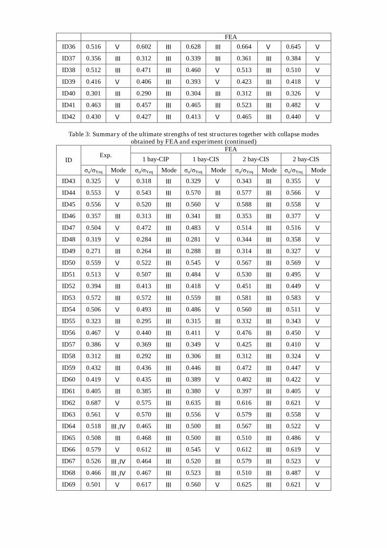
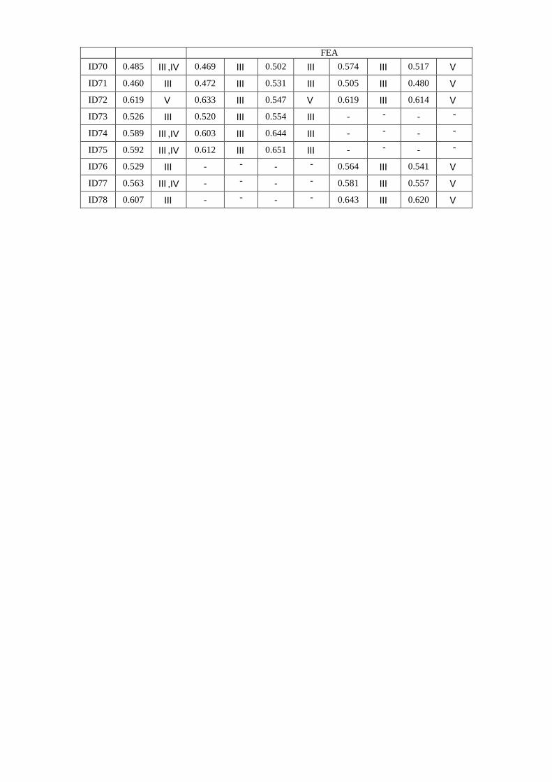
Table 3 summarizes the ultimate strengths of teststructures together with collapse modes obtained by theexperiment and nonlinear FEA. Theoretically, sixprimary modes of stiffened panel collapse underpredominantly axial compressive loads are considered,namely (Paik & Thayamballi 2003)
Mode I: Overall collapse of plating and stiffeners as aunit;
Mode II: Collapse under predominantly biaxialcompression;
Mode III: Beam-column type collapse; Mode IV: Local buckling of stiffener web; Mode V: Tripping of stiffener; Mode VI: Gross yielding.
It was observed that the panel collapse patterns wereclearly different depending on the panel geometries. Forthe ratio of stiffener web height to web thickness isrelatively large, the stiffened panel mostly collapsed bylateral torsional buckling or tripping (Mode V), whilethe beam-column type collapse (Mode III) took placefor panels with a smaller web height. For some panelswith high T-bars, local web buckling (Mode IV) tendsto occur.
Also, from the numerical computations, it isobserved that the 2-bay FEA models give greaterultimate strength values than the 1-bay FEA modelsbecause the effect of rotational restraints along thetransverse frames is taken into account in the 2-bay FEAmodels.
Closed-form ULS formulae
In ship design, the hull girder strength of ships isoften governed by the buckling collapse behavior ofdeck or bottom panels. Hence the calculation of thebuckling collapse strength of stiffened panels in deckand bottom structures under axial compressive loads,which are a primary load component due to ship’s hullgirder actions, is an essential task.
Closed-form empirical ULS formulae for aluminumstiffened plate structures under axial compressive loadsare derived by the regression analysis of experimentaland numerical database obtained from the present study(Paik 2007b).
To cover a wider range of plate slenderness ratio andcolumn slenderness ratio in the developed ULSformulae, some additional FEA were undertaken forstiffened plate structures with different plate slendernessratio and column slenderness ratio from those ofprototype structures tested in the present study.
When the continuous stiffened plate structure ismodeled as an assembly of plate-stiffener combinations,it is recognized that the ultimate compressive strength ofthe representative plate-stiffener combination isexpressible as follows (Paik & Thayamballi 1997, 2003)
2
5.045
224
23
221
Yeq
u 1CCCCC
(16)
where 1C ~ 5C = coefficients to be determined from
database.For steel stiffened plate structures with an average
level of weld induced initial imperfections, Paik andThayamballi (1997, 2003) determined the coefficients ofEq.(16) by the least square method based on theexperimental database as follows
2
5.042222
Yeq
u 1067.0188.0170.0936.0995.0
(17)
It is to be noted that 2Yeq / is the elastic buckling
stress of a column member simply supported at bothends, and the ultimate strength of a column membershould not be greater than the elastic buckling stress.Eq.(17) is useful for predicting the ultimate compressivestrength of steel stiffened panels with Tee, angle or flatbars, the last type of stiffeners having relatively largecolumn slenderness ratio, when an average level ofinitial imperfections is applied.
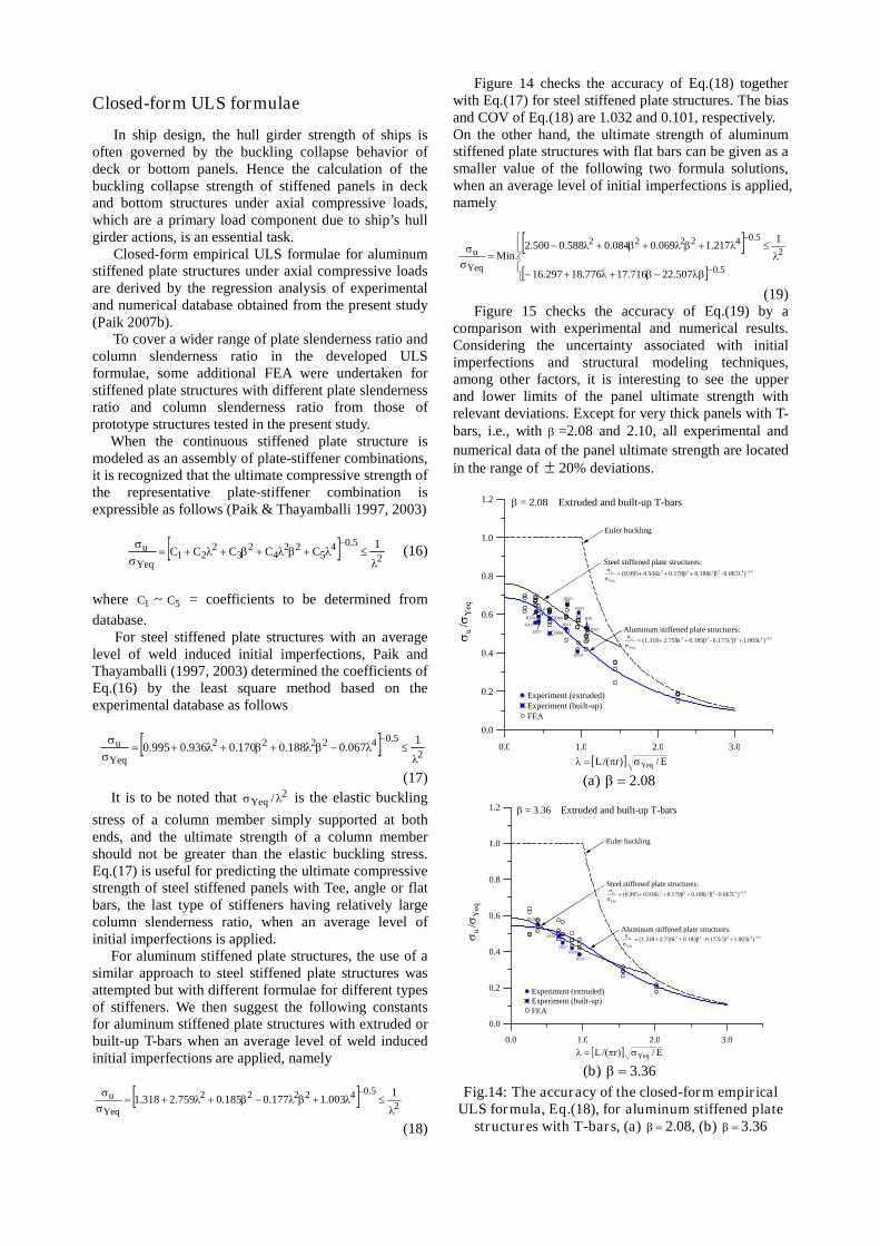
For aluminum stiffened plate structures, the use of asimilar approach to steel stiffened plate structures wasattempted but with different formulae for different typesof stiffeners. We then suggest the following constantsfor aluminum stiffened plate structures with extruded orbuilt-up T-bars when an average level of weld inducedinitial imperfections are applied, namely
2
5.042222
Yeq
u 1003.1177.0185.0759.2318.1
(18)
Figure 14 checks the accuracy of Eq.(18) togetherwith Eq.(17) for steel stiffened plate structures. The biasand COV of Eq.(18) are 1.032 and 0.101, respectively.On the other hand, the ultimate strength of aluminumstiffened plate structures with flat bars can be given as asmaller value of the following two formula solutions,when an average level of initial imperfections is applied,namely
5.0
2
5.042222
Yeq
u
507.22716.17776.18297.16
1217.1069.0084.0588.0500.2
.Min
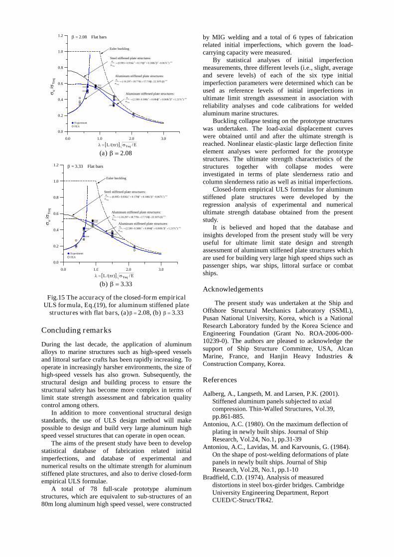
(19)Figure 15 checks the accuracy of Eq.(19) by a
comparison with experimental and numerical results.Considering the uncertainty associated with initialimperfections and structural modeling techniques,among other factors, it is interesting to see the upperand lower limits of the panel ultimate strength withrelevant deviations. Except for very thick panels with T-bars, i.e., with =2.08 and 2.10, all experimental and
numerical data of the panel ultimate strength are locatedin the range of 20% deviations.
0.0 1.0 2.0 3.0
0.0
0.2
0.4
0.6
0.8
1.0
1.2
u/
Yeq
= 2.08 Extruded and built-up T-bars
Euler buckling
Experiment (extruded)
E/)r/(L Yeq
ID69
ID11
ID9
ID21
ID22
ID23
ID12
ID77
ID24
ID74
ID66
ID10
Experiment (built-up)FEA
0.542222
Yeq
u )0.067λ-β0.188λ0.170β0.936λ(0.995σ
σ
Steel stiffened plate structures:
Aluminum stiffened plate structures:0.542222
Yeq
u )1.003λβ0.177λ-0.185β2.759λ(1.318σ
σ
(a) 08.2
0.0 1.0 2.0 3.0
0.0
0.2
0.4
0.6
0.8
1.0
1.2
E/)r/(L Yeq
= 3.36 Extruded and built-up T-bars
ID25
ID26ID27
ID28
ID70u/
Yeq
Experiment (extruded)Experiment (built-up)FEA
Euler buckling
0.542222
Yeq
u )0.067λ-β0.188λ0.170β0.936λ(0.995σ
σ
Steel stiffened plate structures:
Aluminum stiffened plate structures:0.542222
Yeq
u )1.003λβ0.177λ-0.185β2.759λ(1.318σ
σ
(b) 36.3
Fig.14: The accuracy of the closed-form empiricalULS formula, Eq.(18), for aluminum stiffened plate
structures with T-bars, (a) 2.08, (b) 3.36
0.0 1.0 2.0 3.0
0.0
0.2
0.4
0.6
0.8
1.0
1.2
u
/Y
eq
= 2.08 Flat bars
E/)r/(L Yeq
Experiment
FEA
ID54
ID45ID53ID44
ID52
ID43
Euler buckling
Aluminum stiffened plate structures:
0.542222
Yeq
u )λ217.1β0.069λβ084.00.588λ-(2.500σ
σ
0.5
Yeq
u β)22.507λ-β716.1718.776λ(-16.297σ
σ
0.542222
Yeq
u )0.067λ-β0.188λ0.170β0.936λ(0.995σ
σ
Steel stiffened plate structures:
Aluminum stiffened plate structures:
(a) 08.2
0.0 1.0 2.0 3.0
0.0
0.2
0.4
0.6
0.8
1.0
1.2
u/
Yeq
= 3.33 Flat bars
E/)r/(L Yeq
Experiment
FEA
ID37ID46
ID47ID38
ID39
ID48
Euler buckling
Aluminum stiffened plate structures:
0.542222
Yeq
u )λ217.1β0.069λβ084.00.588λ-(2.500σ
σ
0.5
Yeq
u β)22.507λ-β716.1718.776λ(-16.297σ
σ
0.542222
Yeq
u )0.067λ-β0.188λ0.170β0.936λ(0.995σ
σ
Steel stiffened plate structures:
Aluminum stiffened plate structures:
(b) 33.3
Fig.15 The accuracy of the closed-form empiricalULS formula, Eq.(19), for aluminum stiffened plate
structures with flat bars, (a) 2.08, (b) 3.33
Concluding remarks
During the last decade, the application of aluminumalloys to marine structures such as high-speed vesselsand littoral surface crafts has been rapidly increasing. Tooperate in increasingly harsher environments, the size ofhigh-speed vessels has also grown. Subsequently, thestructural design and building process to ensure thestructural safety has become more complex in terms oflimit state strength assessment and fabrication qualitycontrol among others.
In addition to more conventional structural designstandards, the use of ULS design method will makepossible to design and build very large aluminum highspeed vessel structures that can operate in open ocean.
The aims of the present study have been to developstatistical database of fabrication related initialimperfections, and database of experimental andnumerical results on the ultimate strength for aluminumstiffened plate structures, and also to derive closed-formempirical ULS formulae.
A total of 78 full-scale prototype aluminumstructures, which are equivalent to sub-structures of an80m long aluminum high speed vessel, were constructed
by MIG welding and a total of 6 types of fabricationrelated initial imperfections, which govern the load-carrying capacity were measured.
By statistical analyses of initial imperfectionmeasurements, three different levels (i.e., slight, averageand severe levels) of each of the six type initialimperfection parameters were determined which can beused as reference levels of initial imperfections inultimate limit strength assessment in association withreliability analyses and code calibrations for weldedaluminum marine structures.
Buckling collapse testing on the prototype structureswas undertaken. The load-axial displacement curveswere obtained until and after the ultimate strength isreached. Nonlinear elastic-plastic large deflection finiteelement analyses were performed for the prototypestructures. The ultimate strength characteristics of thestructures together with collapse modes wereinvestigated in terms of plate slenderness ratio andcolumn slenderness ratio as well as initial imperfections.
Closed-form empirical ULS formulas for aluminumstiffened plate structures were developed by theregression analysis of experimental and numericalultimate strength database obtained from the presentstudy.
It is believed and hoped that the database andinsights developed from the present study will be veryuseful for ultimate limit state design and strengthassessment of aluminum stiffened plate structures whichare used for building very large high speed ships such aspassenger ships, war ships, littoral surface or combatships.
Acknowledgements
The present study was undertaken at the Ship andOffshore Structural Mechanics Laboratory (SSML),Pusan National University, Korea, which is a NationalResearch Laboratory funded by the Korea Science andEngineering Foundation (Grant No. ROA-2006-000-10239-0). The authors are pleased to acknowledge thesupport of Ship Structure Committee, USA, AlcanMarine, France, and Hanjin Heavy Industries &Construction Company, Korea.
References
Aalberg, A., Langseth, M. and Larsen, P.K. (2001).Stiffened aluminum panels subjected to axialcompression. Thin-Walled Structures, Vol.39,pp.861-885.
Antoniou, A.C. (1980). On the maximum deflection ofplating in newly built ships. Journal of ShipResearch, Vol.24, No.1, pp.31-39
Antoniou, A.C., Lavidas, M. and Karvounis, G. (1984).On the shape of post-welding deformations of platepanels in newly built ships. Journal of ShipResearch, Vol.28, No.1, pp.1-10
Bradfield, C.D. (1974). Analysis of measureddistortions in steel box-girder bridges. CambridgeUniversity Engineering Department, ReportCUED/C-Struct/TR42.
Carlsen, C.A. and Czujko, J. (1978). The specificationof postwelding distortion tolerances for stiffenedplates in compression. The Structural Engineer,Vol.56A, No.5, pp.133-141
Czujko, J. and Kmiecik, M. (1975). Post weldingdistortions of ship shell plating. Ship ResearchInstitute Report No.4-5, Technical University ofSzczecin, Poland.
Czujko, J. (1980). Probabilistic estimation of loadcarrying capacity of axially compressed plates withrandom post-welding distortions. The NorwegianInstitute of Technology, The University ofTrondheim, Norway.
DNV (2003). Rules for ships / high speed, light craftand naval surface craft. Det Norske Veritas, Oslo,Norway
Ellis, L.G. (1977). A statistical appraisal of the measureddeformations in several steel box girder bridge.Journal of Strain Analysis, Vol.12, No.2, pp.97-106.
EN 13195-1 (2002). Aluminum and aluminum alloys:wrought and cast products for marine applications(shipbuilding, marine and offshore). EuropeanStandard: French Standard, Association Francaise deNormalisation (AFNOR), Pasris.
Faulkner, D. (1975). A review of effective plating foruse in the analysis of stiffened plating in bendingand compression. Journal of Ship Research, Vol.19,No.1, pp.1-17
Hopperstad, O.S., Langseth, M. and Hanssen, L. (1998).Ultimate compressive strength of plate elements inaluminum: Correlation of finite element analysesand tests. Thin-Walled Structures, Vol. 29, pp.31-46.
Hopperstad, O.S., Langseth, M. and Tryland, T. (1999).Ultimate strength of aluminum alloy outstands incompression: experiments and simplified analyses.Thin-Walled Structures, Vol. 34, pp. 279-294.
Kmiecik, M (1970). The load carrying capacity ofaxially loaded longitudinally stiffened plates havinginitial deformation. Ship Research Institute ReportNo.R80, Technical University of Szczecin, Poland.
Kmiecik, M. (1971). Behavior of axially loaded simplysupported long rectangular plates having initialdeformations. SFI, Trondheim, Norway.
Kmiecik, M. (1981). Factors affecting the load-carryingcapacity of plates. Ship Research Institute ReportNo.115, Technical University of Szczecin, Poland.
Kmiecik, M. (1986-1987). A review of fabricationdistortion tolerances for ship plating in the light ofthe compressive strength of plates. Paper No.6,Lloyd’s Register Technical Association, London.
Kmiecik, M., Jastrzebski, T. and Kuzniar, J. (1995).Statistics of ship plating distortions. MarineStructures, Vol.8, pp.119-132.
Kontoleon, M.J., Preftitsi, F.G. and Baniotopoulos, C.C.(2000). Butt-welded aluminum joints: a numericalstudy of the HAZ effect on the ultimate tensionstrength. The paramount role of joints into thereliable response of structures, Edited by C.C.Baniotopoulos and F. Wald, pp. 337-346.
Masubuchi, K. (1980). Analysis of welded structures –Residual stresses, distortion and their consequences.Pergamon Press, Oxford.
Matsuoka, K., Tanaka, Y. and Fujita, Y. (1998).Buckling strength of lightened aluminum hullstructures. Proceedings of INALCO’98,International Conference on Aluminum StructuralDesign, Cambridge, UK, April 15-17.
Mazzolani, F.M. (1985). Aluminum alloy structures.Pitman Advanced Publishing Program, Boston.
Mofflin, D.S. (1983). Plate buckling in steel andaluminum. Ph.D. Thesis, University of Cambridge,UK.
Mofflin, D.S. and Dwight, J.B. (1984). Buckling ofaluminum plates in compression. In: Behavior ofThin-Walled Structures, Elsevier, pp.399-427.
Paik, J.K., et al. (2006). The statistics of weld inducedinitial imperfections in aluminum stiffened platestructures for marine application. InternationalJournal of Maritime Engineering, Vol.148, Part A4,pp.1-50.
Paik, J.K. (2007a). Characteristics of welding inducedinitial deflections in welded aluminum plates. Thin-Walled Structures, Vol.45, pp.493-501.
Paik, J.K. (2007b). Empirical formulations forpredicting the ultimate compressive strength ofwelded aluminum stiffened panels. Thin-WalledStructures, Vol.45, pp.171-184.
Paik, J.K. and Thayamballi, A.K. (1997). An empiricalformulation for predicting the ultimate compressivestrength if stiffened panels. Proceedings ofInternational Offshore and Polar EngineeringConference, Honolulu, Vol.IV, pp.328-338.
Paik, J.K. and Thayamballi, A.K. (2003). Ultimate limitstate design of steel-plated structures. John Wiley &Sons, Chichester, UK.
Paik, J.K. and Thayamballi, A.K. (2007). Ship-shapedoffshore installations: Design, building, andoperation. Cambridge University Press, Cambridge,UK.
Paik, J.K., Thayamballi, A.K. and Lee, J.M. (2004).Effect of initial deflection shape on the ultimatestrength behavior of welded steel plates underbiaxial compressive loads. Journal of Ship Research,Vol.48, No.1, pp.45-60.
Paik, J.K. and Duran, A. (2004). Ultimate strength ofaluminum plates and stiffened panels for marineapplications. Marine Technology, Vol. 41, No 3, pp.108-121.
Paik, J.K., Hughes, O.F., Hess, P.E. and Renaud, C.(2005). Ultimate limit state design technology foraluminum multi-hull ship structures. SNAMETransactions, Vol. 113, pp.270-305.
Raynaud, G.M. (1995). New aluminum products forhigh speed light crafts. Building High-speedAluminum Marine Vessels in Victoria – AFeasibility Study, Business Victoria, Melbourne,Australia.
Smith, C.S. and Dow, R.S. (1984). Effects of localizedimperfections on compressive strength of longrectangular plates. Journal of Constructional SteelResearch, Vol.4, pp.51-76
Smith, C.S., Davidson, P.C., Chapman, J.C. andDowling, P.J. (1988). Strength and stiffness ofships’ plating under in-plane compression andtension, RINA Transactions, Vol. 130, pp. 277-296.
Somerville, W.L., Swan, J.W. and Clarke, J.D. (1977).Measurement of residual stresses and distortions instiffened panels. Journal of Strain Analysis, Vol.12,No.2, pp.107-116.
Timoshenko, S.P. and Gere, J.M. (1961). Theory ofelastic stability. McGraw-Hill, New York.Timoshenko, S.P. and Woinowsky-Krieger, S. (1981).Theory of plates and shells. McGraw-Hill, NewYork.
Tanaka, Y. and Matsuoka, K. (1997). Buckling strengthof lightened aluminum hull structures. Proceedingsof the 7th International Offshore and PolarEngineering Conference, Vol.4, Honolulu, pp.790-797.
Ueda, Y. and Yao, T. (1985). The influence of complexinitial deflection modes on the behavior and ultimatestrength of rectangular plates in compression.Journal of Constructional Steel Research, Vol.5,pp.265-302
Zha, Y., Moan, T. and Hanken, E. (2000). Experimentaland numerical studies of torsional buckling ofstiffener in aluminum panels. Proceedings of the 8th
International Offshore and Polar EngineeringConference, Seattle, pp.249-255.
Zha, Y. and Moan, T. (2001). Ultimate strength ofstiffened aluminum panels with predominantlytorsional failure modes. Thin-Walled Structures,Vol.39, No.8, pp.631-648.
Zha, Y. and Moan, T. (2003). Experimental andnumerical collapse prediction of flat bar stiffeners inaluminum panels. Journal of Structural Engineering,Vol.129, No.2, pp.160-168.
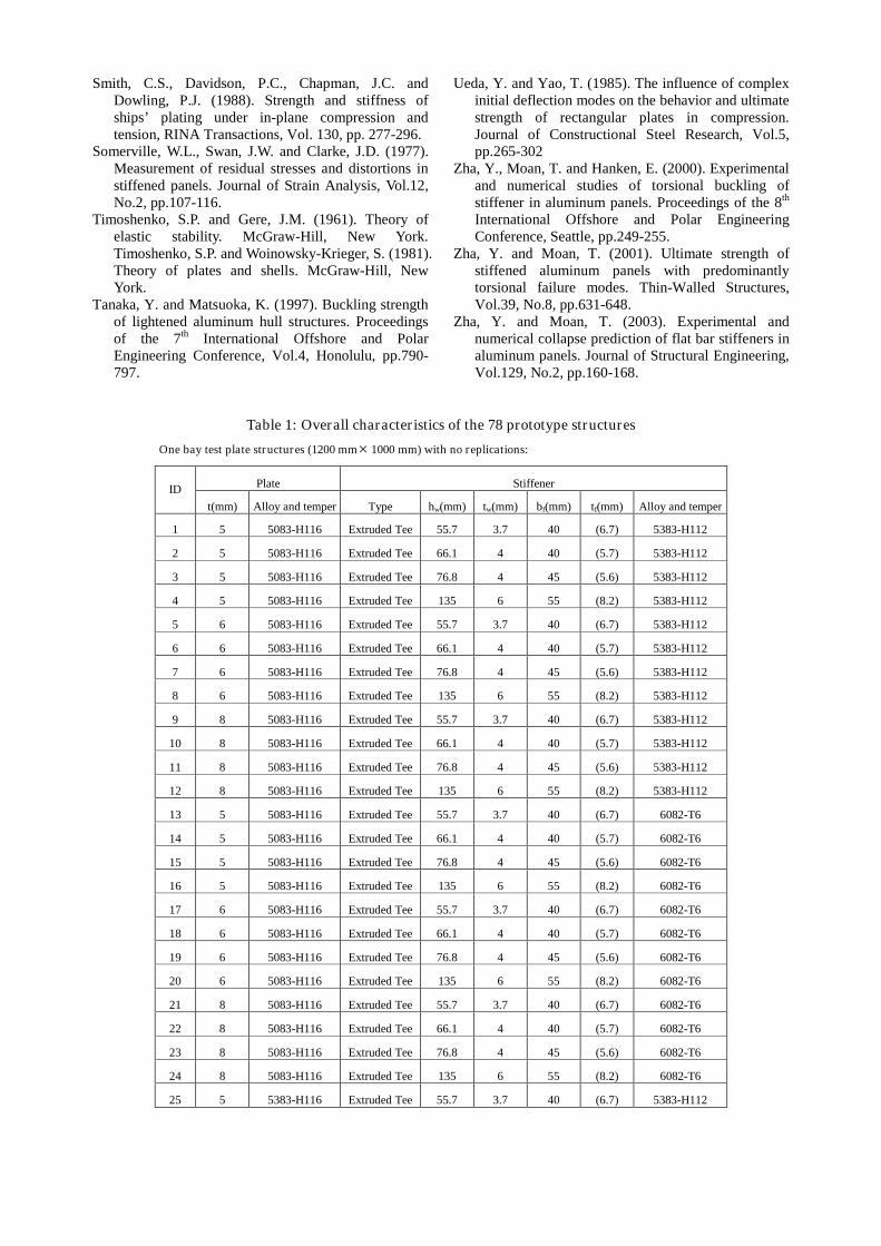
Table 1: Overall characteristics of the 78 prototype structures
One bay test plate structures (1200 mm 1000 mm) with no replications:
Plate StiffenerID
t(mm) Alloy and temper Type hw(mm) tw(mm) bf(mm) tf(mm) Alloy and temper
1 5 5083-H116 Extruded Tee 55.7 3.7 40 (6.7) 5383-H112
2 5 5083-H116 Extruded Tee 66.1 4 40 (5.7) 5383-H112
3 5 5083-H116 Extruded Tee 76.8 4 45 (5.6) 5383-H112
4 5 5083-H116 Extruded Tee 135 6 55 (8.2) 5383-H112
5 6 5083-H116 Extruded Tee 55.7 3.7 40 (6.7) 5383-H112
6 6 5083-H116 Extruded Tee 66.1 4 40 (5.7) 5383-H112
7 6 5083-H116 Extruded Tee 76.8 4 45 (5.6) 5383-H112
8 6 5083-H116 Extruded Tee 135 6 55 (8.2) 5383-H112
9 8 5083-H116 Extruded Tee 55.7 3.7 40 (6.7) 5383-H112
10 8 5083-H116 Extruded Tee 66.1 4 40 (5.7) 5383-H112
11 8 5083-H116 Extruded Tee 76.8 4 45 (5.6) 5383-H112
12 8 5083-H116 Extruded Tee 135 6 55 (8.2) 5383-H112
13 5 5083-H116 Extruded Tee 55.7 3.7 40 (6.7) 6082-T6
14 5 5083-H116 Extruded Tee 66.1 4 40 (5.7) 6082-T6
15 5 5083-H116 Extruded Tee 76.8 4 45 (5.6) 6082-T6
16 5 5083-H116 Extruded Tee 135 6 55 (8.2) 6082-T6
17 6 5083-H116 Extruded Tee 55.7 3.7 40 (6.7) 6082-T6
18 6 5083-H116 Extruded Tee 66.1 4 40 (5.7) 6082-T6
19 6 5083-H116 Extruded Tee 76.8 4 45 (5.6) 6082-T6
20 6 5083-H116 Extruded Tee 135 6 55 (8.2) 6082-T6
21 8 5083-H116 Extruded Tee 55.7 3.7 40 (6.7) 6082-T6
22 8 5083-H116 Extruded Tee 66.1 4 40 (5.7) 6082-T6
23 8 5083-H116 Extruded Tee 76.8 4 45 (5.6) 6082-T6
24 8 5083-H116 Extruded Tee 135 6 55 (8.2) 6082-T6
25 5 5383-H116 Extruded Tee 55.7 3.7 40 (6.7) 5383-H112
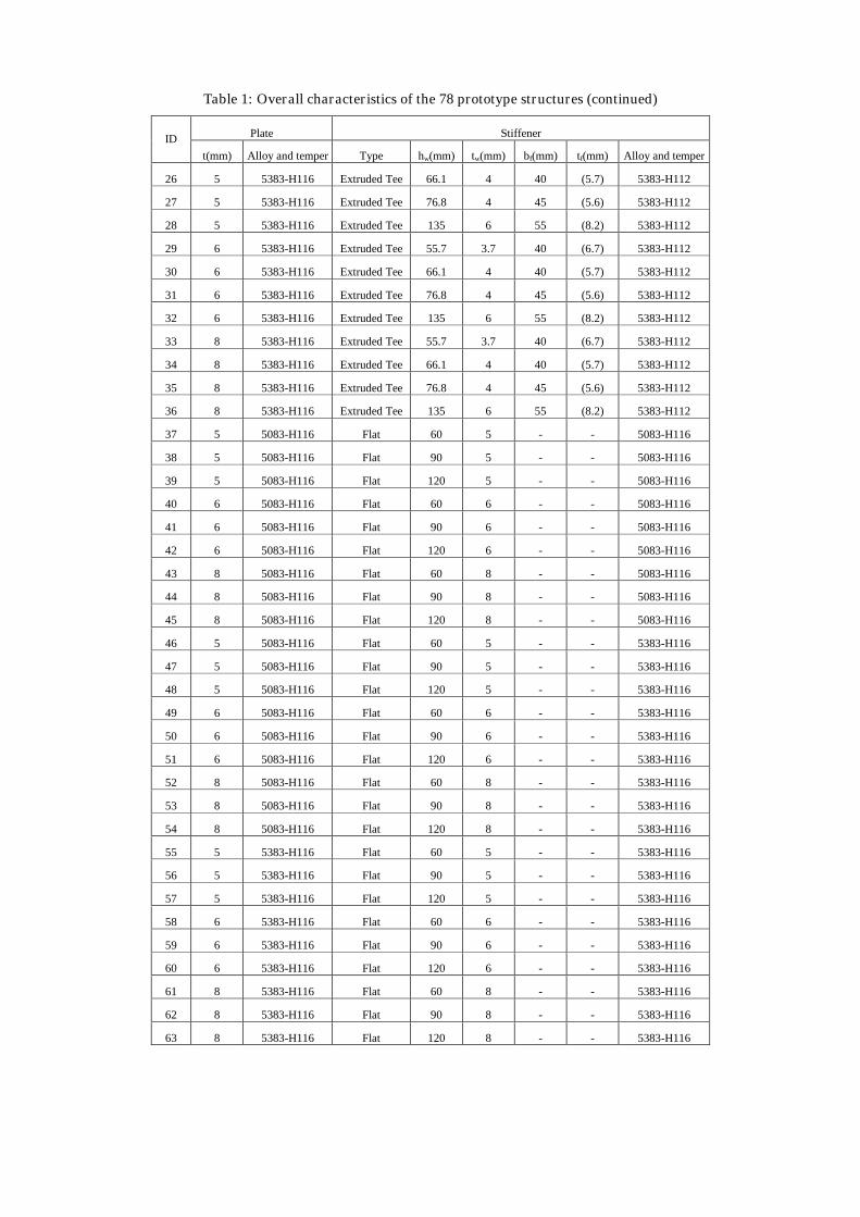
Table 1: Overall characteristics of the 78 prototype structures (continued)
Plate StiffenerID
t(mm) Alloy and temper Type hw(mm) tw(mm) bf(mm) tf(mm) Alloy and temper
26 5 5383-H116 Extruded Tee 66.1 4 40 (5.7) 5383-H112
27 5 5383-H116 Extruded Tee 76.8 4 45 (5.6) 5383-H112
28 5 5383-H116 Extruded Tee 135 6 55 (8.2) 5383-H112
29 6 5383-H116 Extruded Tee 55.7 3.7 40 (6.7) 5383-H112
30 6 5383-H116 Extruded Tee 66.1 4 40 (5.7) 5383-H112
31 6 5383-H116 Extruded Tee 76.8 4 45 (5.6) 5383-H112
32 6 5383-H116 Extruded Tee 135 6 55 (8.2) 5383-H112
33 8 5383-H116 Extruded Tee 55.7 3.7 40 (6.7) 5383-H112
34 8 5383-H116 Extruded Tee 66.1 4 40 (5.7) 5383-H112
35 8 5383-H116 Extruded Tee 76.8 4 45 (5.6) 5383-H112
36 8 5383-H116 Extruded Tee 135 6 55 (8.2) 5383-H112
37 5 5083-H116 Flat 60 5 - - 5083-H116
38 5 5083-H116 Flat 90 5 - - 5083-H116
39 5 5083-H116 Flat 120 5 - - 5083-H116
40 6 5083-H116 Flat 60 6 - - 5083-H116
41 6 5083-H116 Flat 90 6 - - 5083-H116
42 6 5083-H116 Flat 120 6 - - 5083-H116
43 8 5083-H116 Flat 60 8 - - 5083-H116
44 8 5083-H116 Flat 90 8 - - 5083-H116
45 8 5083-H116 Flat 120 8 - - 5083-H116
46 5 5083-H116 Flat 60 5 - - 5383-H116
47 5 5083-H116 Flat 90 5 - - 5383-H116
48 5 5083-H116 Flat 120 5 - - 5383-H116
49 6 5083-H116 Flat 60 6 - - 5383-H116
50 6 5083-H116 Flat 90 6 - - 5383-H116
51 6 5083-H116 Flat 120 6 - - 5383-H116
52 8 5083-H116 Flat 60 8 - - 5383-H116
53 8 5083-H116 Flat 90 8 - - 5383-H116
54 8 5083-H116 Flat 120 8 - - 5383-H116
55 5 5383-H116 Flat 60 5 - - 5383-H116
56 5 5383-H116 Flat 90 5 - - 5383-H116
57 5 5383-H116 Flat 120 5 - - 5383-H116
58 6 5383-H116 Flat 60 6 - - 5383-H116
59 6 5383-H116 Flat 90 6 - - 5383-H116
60 6 5383-H116 Flat 120 6 - - 5383-H116
61 8 5383-H116 Flat 60 8 - - 5383-H116
62 8 5383-H116 Flat 90 8 - - 5383-H116
63 8 5383-H116 Flat 120 8 - - 5383-H116
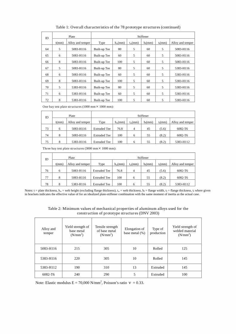
Table 1: Overall characteristics of the 78 prototype structures (continued)
Plate StiffenerID
t(mm) Alloy and temper Type hw(mm) tw(mm) bf(mm) tf(mm) Alloy and temper
64 5 5083-H116 Built-up Tee 80 5 60 5 5083-H116
65 6 5083-H116 Built-up Tee 60 5 60 5 5083-H116
66 8 5083-H116 Built-up Tee 100 5 60 5 5083-H116
67 5 5083-H116 Built-up Tee 80 5 60 5 5383-H116
68 6 5083-H116 Built-up Tee 60 5 60 5 5383-H116
69 8 5083-H116 Built-up Tee 100 5 60 5 5383-H116
70 5 5383-H116 Built-up Tee 80 5 60 5 5383-H116
71 6 5383-H116 Built-up Tee 60 5 60 5 5383-H116
72 8 5383-H116 Built-up Tee 100 5 60 5 5383-H116
One bay test plate structures (1000 mm 1000 mm):
Plate StiffenerID
t(mm) Alloy and temper Type hw(mm) tw(mm) bf(mm) tf(mm) Alloy and temper
73 6 5083-H116 Extruded Tee 76.8 4 45 (5.6) 6082-T6
74 8 5083-H116 Extruded Tee 100 6 55 (8.2) 6082-T6
75 8 5383-H116 Extruded Tee 100 6 55 (8.2) 5383-H112
Three bay test plate structures (3000 mm 1000 mm):
Plate StiffenerID
t(mm) Alloy and temper Type hw(mm) tw(mm) bf(mm) tf(mm) Alloy and temper
76 6 5083-H116 Extruded Tee 76.8 4 45 (5.6) 6082-T6
77 8 5083-H116 Extruded Tee 100 6 55 (8.2) 6082-T6
78 8 5383-H116 Extruded Tee 100 6 55 (8.2) 5383-H112
Notes: t = plate thickness, hw = web height (excluding flange thickness), tw = web thickness, bf = flange width, tf = flange thickness, tf where givenin brackets indicates the effective value of for an idealized plate-stiffener combination with the same moment of inertia as the actual case.
Table 2: Minimum values of mechanical properties of aluminum alloys used for theconstruction of prototype structures (DNV 2003)
Alloy andtemper
Yield strength ofbase metal(N/mm2)
Tensile strengthof base metal
(N/mm2)
Elongation ofbase metal (%)
Type ofproduction
Yield strength ofwelded material
(N/mm2)
5083-H116 215 305 10 Rolled 125
5383-H116 220 305 10 Rolled 145
5383-H112 190 310 13 Extruded 145
6082-T6 240 290 5 Extruded 100
Note: Elastic modulus E = 70,000 N/mm2, Poisson’s ratio = 0.33.
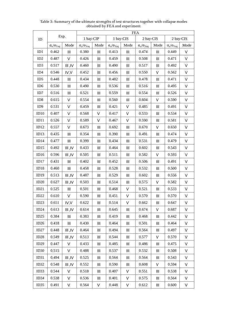
Table 3: Summary of the ultimate strengths of test structures together with collapse modesobtained by FEA and experiment
FEAExp.
1 bay-CIP 1 bay-CIS 2 bay-CIS 2 bay-CISID
σu/σYeq Mode σu/σYeq Mode σu/σYeq Mode σu/σYeq Mode σu/σYeq Mode
ID1 0.462 Ⅲ 0.380 Ⅲ 0.413 Ⅲ 0.474 Ⅲ 0.449 Ⅴ
ID2 0.487 Ⅴ 0.426 Ⅲ 0.459 Ⅲ 0.508 Ⅲ 0.471 Ⅴ
ID3 0.517 Ⅲ ,IV 0.460 Ⅲ 0.490 Ⅲ 0.517 Ⅲ 0.492 Ⅴ
ID4 0.546 IV,Ⅴ 0.452 Ⅲ 0.456 Ⅲ 0.550 Ⅴ 0.562 Ⅴ
ID5 0.448 Ⅲ 0.434 Ⅲ 0.482 Ⅲ 0.478 Ⅲ 0.471 Ⅴ
ID6 0.530 Ⅲ 0.490 Ⅲ 0.536 Ⅲ 0.516 Ⅲ 0.495 Ⅴ
ID7 0.516 Ⅲ 0.521 Ⅲ 0.559 Ⅲ 0.554 Ⅲ 0.526 Ⅴ
ID8 0.615 Ⅴ 0.554 Ⅲ 0.560 Ⅲ 0.604 Ⅴ 0.590 Ⅴ
ID9 0.531 Ⅴ 0.459 Ⅲ 0.421 Ⅴ 0.485 Ⅲ 0.491 Ⅴ
ID10 0.407 Ⅴ 0.568 Ⅴ 0.417 Ⅴ 0.533 Ⅲ 0.534 Ⅴ
ID11 0.526 Ⅴ 0.589 Ⅴ 0.467 Ⅴ 0.590 Ⅲ 0.581 Ⅴ
ID12 0.557 Ⅴ 0.673 Ⅲ 0.692 Ⅲ 0.670 Ⅴ 0.650 Ⅴ
ID13 0.435 Ⅲ 0.354 Ⅲ 0.390 Ⅲ 0.491 Ⅲ 0.474 Ⅴ
ID14 0.477 Ⅲ 0.399 Ⅲ 0.434 Ⅲ 0.531 Ⅲ 0.479 Ⅴ
ID15 0.492 Ⅲ ,IV 0.433 Ⅲ 0.464 Ⅲ 0.602 Ⅲ 0.543 Ⅴ
ID16 0.596 Ⅲ ,IV 0.505 Ⅲ 0.511 Ⅲ 0.582 Ⅴ 0.593 Ⅴ
ID17 0.431 Ⅲ 0.402 Ⅲ 0.452 Ⅲ 0.506 Ⅲ 0.491 Ⅴ
ID18 0.460 Ⅲ 0.458 Ⅲ 0.528 Ⅲ 0.532 Ⅲ 0.500 Ⅴ
ID19 0.513 Ⅲ ,IV 0.487 Ⅲ 0.529 Ⅲ 0.602 Ⅲ 0.556 Ⅴ
ID20 0.627 Ⅲ ,IV 0.503 Ⅲ 0.514 Ⅲ 0.575 Ⅴ 0.582 Ⅴ
ID21 0.525 Ⅲ 0.501 Ⅲ 0.468 Ⅴ 0.521 Ⅲ 0.533 Ⅴ
ID22 0.610 Ⅴ 0.590 Ⅲ 0.451 Ⅴ 0.570 Ⅲ 0.570 Ⅴ
ID23 0.651 IV,Ⅴ 0.622 Ⅲ 0.514 Ⅴ 0.662 Ⅲ 0.647 Ⅴ
ID24 0.613 Ⅲ ,IV 0.614 Ⅲ 0.645 Ⅲ 0.674 Ⅴ 0.687 Ⅴ
ID25 0.384 Ⅲ 0.383 Ⅲ 0.419 Ⅲ 0.468 Ⅲ 0.442 Ⅴ
ID26 0.418 Ⅲ 0.430 Ⅲ 0.464 Ⅲ 0.501 Ⅲ 0.464 Ⅴ
ID27 0.448 Ⅲ ,IV 0.464 Ⅲ 0.494 Ⅲ 0.564 Ⅲ 0.497 Ⅴ
ID28 0.549 Ⅲ ,IV 0.513 Ⅲ 0.544 Ⅲ 0.577 Ⅴ 0.570 Ⅴ
ID29 0.447 Ⅴ 0.433 Ⅲ 0.485 Ⅲ 0.486 Ⅲ 0.475 Ⅴ
ID30 0.515 Ⅴ 0.488 Ⅲ 0.537 Ⅲ 0.532 Ⅲ 0.508 Ⅴ
ID31 0.494 Ⅲ ,IV 0.525 Ⅲ 0.564 Ⅲ 0.564 Ⅲ 0.543 Ⅴ
ID32 0.548 Ⅲ ,IV 0.552 Ⅲ 0.590 Ⅲ 0.608 Ⅴ 0.594 Ⅴ
ID33 0.544 Ⅴ 0.518 Ⅲ 0.407 Ⅴ 0.551 Ⅲ 0.538 Ⅴ
ID34 0.538 Ⅴ 0.536 Ⅲ 0.401 Ⅴ 0.575 Ⅲ 0.564 Ⅴ
ID35 0.491 Ⅴ 0.564 Ⅴ 0.448 Ⅴ 0.612 Ⅲ 0.600 Ⅴ
FEA
ID36 0.516 Ⅴ 0.602 Ⅲ 0.628 Ⅲ 0.664 Ⅴ 0.645 Ⅴ
ID37 0.356 Ⅲ 0.312 Ⅲ 0.339 Ⅲ 0.361 Ⅲ 0.384 Ⅴ
ID38 0.512 Ⅲ 0.471 Ⅲ 0.460 Ⅴ 0.513 Ⅲ 0.510 Ⅴ
ID39 0.416 Ⅴ 0.406 Ⅲ 0.393 Ⅴ 0.423 Ⅲ 0.418 Ⅴ
ID40 0.301 Ⅲ 0.290 Ⅲ 0.304 Ⅲ 0.312 Ⅲ 0.326 Ⅴ
ID41 0.463 Ⅲ 0.457 Ⅲ 0.465 Ⅲ 0.523 Ⅲ 0.482 Ⅴ
ID42 0.430 Ⅴ 0.427 Ⅲ 0.413 Ⅴ 0.465 Ⅲ 0.440 Ⅴ
Table 3: Summary of the ultimate strengths of test structures together with collapse modesobtained by FEA and experiment (continued)
FEAExp.
1 bay-CIP 1 bay-CIS 2 bay-CIS 2 bay-CISID
σu/σYeq Mode σu/σYeq Mode σu/σYeq Mode σu/σYeq Mode σu/σYeq Mode
ID43 0.325 Ⅴ 0.318 Ⅲ 0.329 Ⅴ 0.343 Ⅲ 0.355 Ⅴ
ID44 0.553 Ⅴ 0.543 Ⅲ 0.570 Ⅲ 0.577 Ⅲ 0.566 Ⅴ
ID45 0.556 Ⅴ 0.520 Ⅲ 0.560 Ⅴ 0.588 Ⅲ 0.558 Ⅴ
ID46 0.357 Ⅲ 0.313 Ⅲ 0.341 Ⅲ 0.353 Ⅲ 0.377 Ⅴ
ID47 0.504 Ⅴ 0.472 Ⅲ 0.483 Ⅴ 0.514 Ⅲ 0.516 Ⅴ
ID48 0.319 Ⅴ 0.284 Ⅲ 0.281 Ⅴ 0.344 Ⅲ 0.358 Ⅴ
ID49 0.271 Ⅲ 0.264 Ⅲ 0.288 Ⅲ 0.314 Ⅲ 0.327 Ⅴ
ID50 0.559 Ⅴ 0.522 Ⅲ 0.545 Ⅴ 0.567 Ⅲ 0.569 Ⅴ
ID51 0.513 Ⅴ 0.507 Ⅲ 0.484 Ⅴ 0.530 Ⅲ 0.495 Ⅴ
ID52 0.394 Ⅲ 0.413 Ⅲ 0.418 Ⅴ 0.451 Ⅲ 0.449 Ⅴ
ID53 0.572 Ⅲ 0.572 Ⅲ 0.559 Ⅲ 0.581 Ⅲ 0.583 Ⅴ
ID54 0.506 Ⅴ 0.493 Ⅲ 0.486 Ⅴ 0.560 Ⅲ 0.511 Ⅴ
ID55 0.323 Ⅲ 0.295 Ⅲ 0.315 Ⅲ 0.332 Ⅲ 0.343 Ⅴ
ID56 0.467 Ⅴ 0.440 Ⅲ 0.411 Ⅴ 0.476 Ⅲ 0.450 Ⅴ
ID57 0.386 Ⅴ 0.369 Ⅲ 0.349 Ⅴ 0.425 Ⅲ 0.410 Ⅴ
ID58 0.312 Ⅲ 0.292 Ⅲ 0.306 Ⅲ 0.312 Ⅲ 0.324 Ⅴ
ID59 0.432 Ⅲ 0.436 Ⅲ 0.446 Ⅲ 0.472 Ⅲ 0.447 Ⅴ
ID60 0.419 Ⅴ 0.435 Ⅲ 0.389 Ⅴ 0.402 Ⅲ 0.422 Ⅴ
ID61 0.405 Ⅲ 0.385 Ⅲ 0.380 Ⅴ 0.397 Ⅲ 0.405 Ⅴ
ID62 0.687 Ⅴ 0.575 Ⅲ 0.635 Ⅲ 0.616 Ⅲ 0.621 Ⅴ
ID63 0.561 Ⅴ 0.570 Ⅲ 0.556 Ⅴ 0.579 Ⅲ 0.558 Ⅴ
ID64 0.518 Ⅲ ,IV 0.465 Ⅲ 0.500 Ⅲ 0.567 Ⅲ 0.522 Ⅴ
ID65 0.508 Ⅲ 0.468 Ⅲ 0.500 Ⅲ 0.510 Ⅲ 0.486 Ⅴ
ID66 0.579 Ⅴ 0.612 Ⅲ 0.545 Ⅴ 0.612 Ⅲ 0.619 Ⅴ
ID67 0.526 Ⅲ ,IV 0.464 Ⅲ 0.520 Ⅲ 0.579 Ⅲ 0.523 Ⅴ
ID68 0.466 Ⅲ ,IV 0.467 Ⅲ 0.523 Ⅲ 0.510 Ⅲ 0.487 Ⅴ
ID69 0.501 Ⅴ 0.617 Ⅲ 0.560 Ⅴ 0.625 Ⅲ 0.621 Ⅴ
FEA
ID70 0.485 Ⅲ ,IV 0.469 Ⅲ 0.502 Ⅲ 0.574 Ⅲ 0.517 Ⅴ
ID71 0.460 Ⅲ 0.472 Ⅲ 0.531 Ⅲ 0.505 Ⅲ 0.480 Ⅴ
ID72 0.619 Ⅴ 0.633 Ⅲ 0.547 Ⅴ 0.619 Ⅲ 0.614 Ⅴ
ID73 0.526 Ⅲ 0.520 Ⅲ 0.554 Ⅲ - - - -
ID74 0.589 Ⅲ ,IV 0.603 Ⅲ 0.644 Ⅲ - - - -
ID75 0.592 Ⅲ ,IV 0.612 Ⅲ 0.651 Ⅲ - - - -
ID76 0.529 Ⅲ - - - - 0.564 Ⅲ 0.541 Ⅴ
ID77 0.563 Ⅲ ,IV - - - - 0.581 Ⅲ 0.557 Ⅴ
ID78 0.607 Ⅲ - - - - 0.643 Ⅲ 0.620 Ⅴ