Mechanical Behavior of Orange Peel Reinforced Epoxy Composite...
37
Mechanical Behavior of Orange Peel Reinforced Epoxy Composite A THESIS SUBMITTED IN PARTIAL FULFILMENT OF THE REQUIREMENT FOR THE DEGREE OF Bachelor of Technology In Mechanical Engineering By PRAVEEN KUMAR (108ME066) Department of Mechanical Engineering National Institute of Technology Rourkela (2012)
Transcript of Mechanical Behavior of Orange Peel Reinforced Epoxy Composite...
Mechanical Behavior of Orange Peel Reinforced
Epoxy Composite
A THESIS SUBMITTED IN PARTIAL FULFILMENT OF
THE REQUIREMENT FOR THE DEGREE OF
Bachelor of Technology
In
Mechanical Engineering
By
PRAVEEN KUMAR
(108ME066)
Department of Mechanical Engineering
National Institute of Technology
Rourkela
(2012)

Mechanical Behavior of Orange Peel Reinforced
Epoxy Composite
THESIS SUBMITTED IN PARTIAL FULFILMENT OF
THE REQUIREMENT FOR THE DEGREE OF
Bachelor of Technology
In
Mechanical Engineering
By
PRAVEEN KUMAR
(108ME066)
Under the Guidance of
Prof. S.K. Acharya
Department of Mechanical Engineering
National Institute of Technology
Rourkela
(2012)

i
National Institute of Technology
Rourkela
CERTIFICATE
This is to certify that the thesis entitled, “Mechanical Behavior of Orange Peel Reinforced
Epoxy Composite” submitted by Sri Praveen Kumar in partial fulfillment of the
requirements for the award of Bachelor of Technology Degree in Mechanical Engineering at
the National Institute of Technology, Rourkela (Deemed University) is an authentic work
carried out by him under my supervision and guidance.
To the best of my knowledge, the matter embodied in this thesis has not been submitted to
any other University/Institute for the award of any Degree or Diploma.
Date:
Prof. S.K. Acharya
Department of Mechanical Engineering
National Institute of Technology
Rourkela-769008
ii
ACKNOWLEDGEMENT
It is with a feeling of great pleasure that I would like to express my most sincere heartfelt
gratitude to Prof. S.K. Acharya, Dept. of Mechanical Engineering, NIT Rourkela, for
suggesting the topic for my thesis report and for his ready and able guidance throughout the
course of my preparing the report. I am greatly indebted to him for his constructive
suggestions and criticism from time to time during the course of progress of my work.
I express my sincere thanks to Prof. K.P. Maity, Head of the Department of Mechanical
Engineering, NIT Rourkela, for providing me the necessary facilities in the department.
I express my sincere gratitude to Prof. S. K. Pratihar, Dept. of Ceramic Engineering course
for his timely help during the course of work.
I feel pleased and privileged to fulfill our parents’ ambition and I am greatly indebted to them
for bearing the inconvenience during my M.E. course.
Date:
PRAVEEN KUMAR
(108ME066)

CONTENTS
Page No.
CERTIFICATE i
ACKNOWLEDGEMENT ii
ABSTRACT iii
LIST OF FIGURES iv
LIST OF TABLES v
CHAPTER 1 INTRODUCTION 1
1.1 Overview of composites 1
1.2 Bio Composite 2
1.3 Classification of Natural/ Bio-fibers 3
1.4 Application of natural fiber composites 3
CHAPTER 2 LITERATURE SURVEY 6
2.1 Introduction 6
2.2 Summery of previous work done 8
2.3 Objective of the present work 9
CHAPTER 3 MATERIALS AND METHOD 10
3.1 Materials and Method 10
3.1.1 Orange peel 10
3.1.2 Epoxy resin 11
3.1.3 Hardener
3.2 Composite preparation 12
3.3 Experimental procedure 13
3.3.1 Density measurement 13
3.3.2 Hardness test 14
3.3.3 Tensile test 14
3.3.4 Flexural Strength 15
CHAPTER 4 RESULTS AND DISCUSSION 18
4.1 Density measurement 18
4.2 Hardness test 19
4.3 Tensile test 20
4.4 Flexural test 21
4.5 SEM analysis 22
CHAPTER 5 24
5.1 Conclusions 24
5.2 Recommendation for future research 24
REFERENCES 25
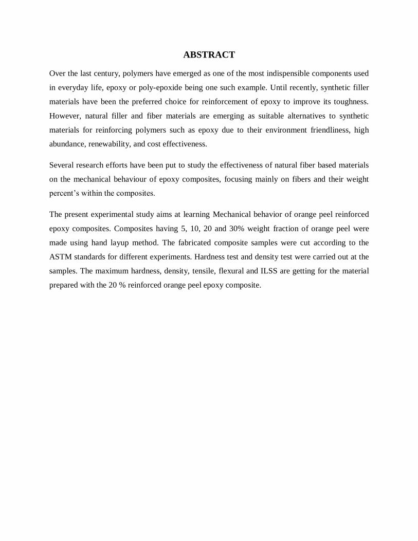
ABSTRACT
Over the last century, polymers have emerged as one of the most indispensible components used
in everyday life, epoxy or poly-epoxide being one such example. Until recently, synthetic filler
materials have been the preferred choice for reinforcement of epoxy to improve its toughness.
However, natural filler and fiber materials are emerging as suitable alternatives to synthetic
materials for reinforcing polymers such as epoxy due to their environment friendliness, high
abundance, renewability, and cost effectiveness.
Several research efforts have been put to study the effectiveness of natural fiber based materials
on the mechanical behaviour of epoxy composites, focusing mainly on fibers and their weight
percent’s within the composites.
The present experimental study aims at learning Mechanical behavior of orange peel reinforced
epoxy composites. Composites having 5, 10, 20 and 30% weight fraction of orange peel were
made using hand layup method. The fabricated composite samples were cut according to the
ASTM standards for different experiments. Hardness test and density test were carried out at the
samples. The maximum hardness, density, tensile, flexural and ILSS are getting for the material
prepared with the 20 % reinforced orange peel epoxy composite.

LIST OF FIGURES
Figure No. Title Page No.
Fig 2.1 Overview of Natural fibers 7
Fig 3.1(a-c) Orange peels, sun dried orange peels,
powdered orange peels 10
Fig 3.2(a-c) Mould used for making the composite,
tensile test specimen, flexural test specimen 12
Fig 3.3 Dog bone shape of the tensile testing sample 15
Fig 3.4 (a-b) UTM machine sample holder, 15
UTM machine sample loaded 15
Fig 3.5(a-b) the loading arrangement for the flexural testing,
flexural specimen loading position 16
Fig 4.1 The variation of density with different fiber contents 18
Fig 4.2 Variation of Vicker Hardness value with different fiber contents 19
Fig 4.3 Variation of Tensile strength with different fiber contents 20
Fig 4.4 Variation of flexural strength with different fiber contents 21
Fig 4.5 Variation of ILSS with different fiber contents 22
Fig 4.6 SEM micrograph of 20% orange peel composite after tensile test 22
Fig 4.7 SEM micrograph of 20% orange peel composite after flexural test 23
iv

LIST OF TABLES
Table No. Title Page No.
Table 1.1 Classification of Natural fibers 3
Table 3.1 Particles Size 11
Table 4.1 Density of different Samples 18
Table 4.2 Hardness of different samples 19
Table 4.3 Tensile Stress and Tensile Modulus of composites 20
Table 4.4 Flexural properties of the composites 21
v

1
CHAPTER 1
INTRODUCTION
1.1 Overview of composites
When two or more material with different properties is combined together they form a
composite material [1]. The constituents are combined in such a way that they keep their
individual physical phases and are non soluble in each other or do not form a new chemical
compound. That is why a composite is considered to be any multi phase material system that
exhibits a combination of properties that makes the composite superior to each of the constituent
phases. This criterion has provided the main motivation for the research and development of
composite material worldwide. There are basically two category of constituent material, one
constituent is called reinforcing phase and one in which the reinforcing phase is embedded is
called matrix. The primary function of matrix is to hold the fiber to form a certain shape.
Besides, the functions of the matrix are also to transfer stress between the reinforcing fibers and
to protect them from mechanical and environmental damage. The function of reinforcing phase
in matrix is to improve the mechanical properties such as strength, stiffness etc. As per
Berghezan [2] the composite material is to be designed in such a way that the individual
component retain their characteristic are so incorporated that the composite take advantage of
their superior properties without compromising on the weakness of either. There are basically
three major types of composite materials available designated as per the matrix material used.
The matrix material can be metallic, polymeric or can even be ceramic. When the matrix is a
polymer, the composite is called polymer matrix composite. Fiber reinforced polymer (FRP)
composite are the most common advanced composites. These composites consist of a polymer
matrix reinforced with thin diameter fibers. The reasons why they are the most common
composite include low cost, high strength, and simple manufacturing processes. There are many
polymer resin system used as matrices in FRP composites. They can be classified as thermo
plastic (polyethylene, polypropylene, nylon etc) and thermoset (epoxies, polyesters, vinyl ester
etc) polymer. Thermoplastic polymer can be repeatedly softened and formed by increasing the
temperature or hardened by decreasing the temperature, while the thermoset polymers are
insoluble and infusible after cure.

2
As far as reinforcement is concerned fibers occupy the largest weight fraction in a FRP
composite and it share its major portion of the load that act on the composite structure. The
reinforcing fibers can be oriented during fabrication there by giving ample opportunity to the
designer to tailor down the properties in specific direction. The major fibers in use today are
glass, carbon and aramid. Recently research on engineering interest have been shifting from
traditional synthetic fiber composite to lignocellulosic natural fiber composite due to their
advantages like high strength to weight ratio, non carcinogenic and biodegradability. The term
natural fiber covers a broad range of vegetables, animal and mineral fibers. Availability of
natural fibers and easy of manufacturing is tempting researcher to try locally available
inexpensive natural fibers as reinforcement material in polymer matrix. The other advantages
associated with natural fibers are non abrasive nature, low energy consumption, biodegradability,
light weight and low cost. Careful selection of reinforcement type enables finished product
characteristics to be tailored to almost any specific engineering requirement. Whilst the use of
composites will be a clear choice in many instances, material selection in others will depend on
factors such as working lifetime requirements, number of items to be produced (run length),
complexity of product shape, possible savings in assembly costs and on the experience & skills
the designer in tapping the optimum potential of composites. In some instances, best results may
be achieved through the use of composites in conjunction with traditional materials.
1.2 Bio composite
Bio composite is a material formed by a matrix and a reinforcement of a plant derived
fiber. It is needed to develop novel bio based products and other innovative technologies that can
reduce widespread dependence on fossil fuels. Eco-friendly bio composites from plant derived
fiber and crop-derived plastics, make a great importance to the environment and is also a solution
to the uncertainty of petroleum supply. Bio polymers are now moving mainstream use, and the
polymers that are biodegradable or based on renewable feedstock may soon be competing with
commodity plastics, as result of the sales growth of more than 20-30% per year and improvement
in the economics of sales. The best examples of biopolymers based on renewable resources are:
cellulosic plastics, polylactides (PLA), starch plastics and soy based plastics. Microbial
synthesized biopolymers, i.e., polyhydroxy alkanoates (PHAs) polymers are also having
attractive environment friendly properties. The use of materials from renewable resources is

3
being popular and the world‟s leading industries are looking forward to use more and more
composite materials derived from natural fibers and bio-polymers in place of petrochemical-
based feedstock.
1.3 Classification of Natural/Bio-fibers
Natural/bio-fibers can be broadly divided into two categories: non-wood fibers and wood
fibers shown in the table 1.1. At present level of technology non wood fibers like hemp, kenaf,
flax and sisal find commercial success in the design of bio-composites from polypropylene for
automotive applications. Increase use of biopolymers would result in more eco-friendly bio-
composites for twenty first century green automotive parts applications. All the natural
reinforcing fibers are lingo-cellulosic, having cellulose and lignin as principle components.
Table 1.1 Classification of Natural fibers
1.4 Application of natural fiber composites
The natural fiber composites can be very cost effective material for following
applications:
Building and construction industry: panels for partition and false ceiling, partition boards,
wall, floor, window and floor frames, roof tiles, mobile pre-fabricated buildings which
can be used in times of natural calamities such as floods, cyclone, earthquakes etc.
Storage devices: post boxes, grain storage silos, bio gas containers etc.

4
Furniture: chair, table, shower, bath units etc.
Electric devices: electrical appliances, pipes etc.
Everyday applications: lampshades, suitcases, helmets etc.
Transportation: automobile and railway coach interior, boat etc.
Toys
The reason for the application of natural fiber composites in the automotive industry includes:
Low density: which may lead to a weight reduction of 10 to 30%
Acceptable mechanical properties, good acoustic properties.
Favorable processing properties, for instance low wear on tools, etc.
Options for new production technologies and materials.
Favorable accident performance, high stability, less splintering.
Favorable eco balance for part production.
Favorable eco balance during vehicle operation due to weight savings.
Occupational health benefits compared to glass fibers during production.
No off-gassing of toxic compounds (in contrast to phenol resin bonded wood and
recycled cotton fiber parts.)
Reduce fogging behavior
Price advantage both for the fibers and the applied technologies.
Composite materials due to their low density, excellent stiffness and good thermal and
mechanical properties are particularly superior to many traditional materials such as metals.
Recent developments on various applications of polymer composite are well documented in
many literatures. Different types of polymer show different Mechanical and tribological
behavior. However neat polymers is very rarely used as bearing materials and wear resistance
material because unmodified polymer could not satisfy the demands arising from the situations
wherein a combination of good mechanical and tribological properties is required [3].
Visualizing the importance of polymer composite reinforced with cellulosic fibers like sisal,
coconut(coir), bamboo, banana in their natural form as well as several waste cellulosic products
5
such as shell flour, wood flour and pulp have been used as reinforcing agents of different
thermosetting and thermoplastic composites.
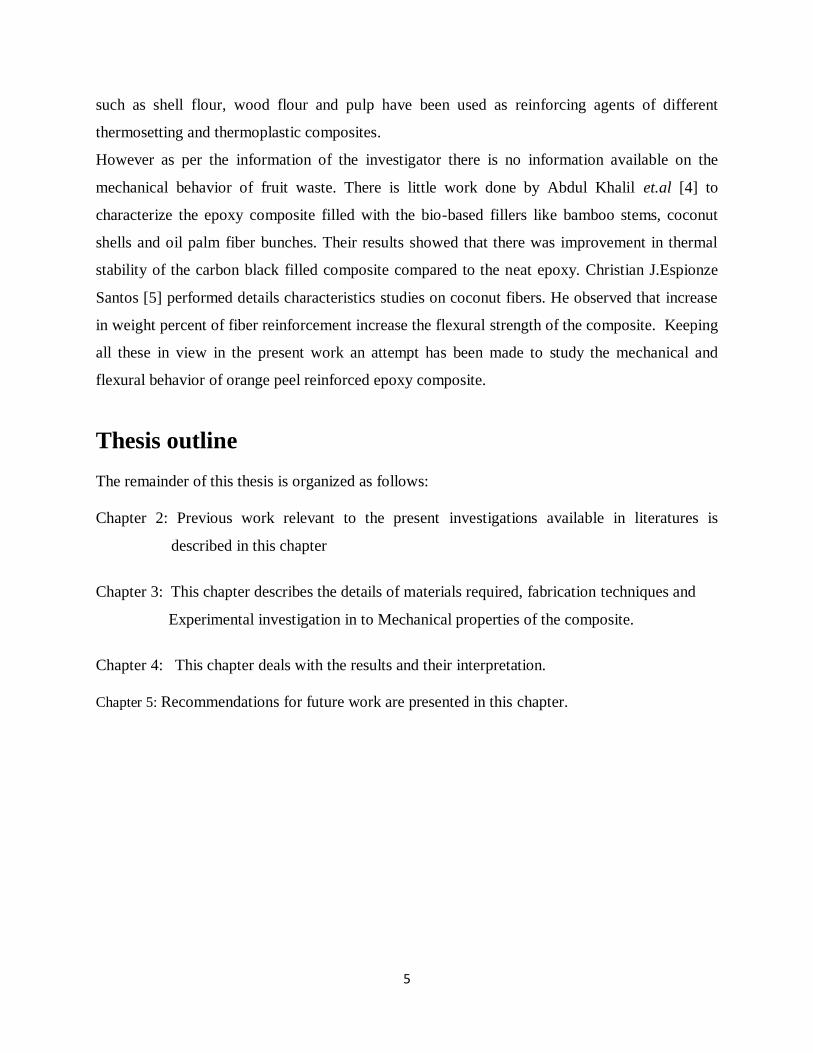
However as per the information of the investigator there is no information available on the
mechanical behavior of fruit waste. There is little work done by Abdul Khalil et.al [4] to
characterize the epoxy composite filled with the bio-based fillers like bamboo stems, coconut
shells and oil palm fiber bunches. Their results showed that there was improvement in thermal
stability of the carbon black filled composite compared to the neat epoxy. Christian J.Espionze
Santos [5] performed details characteristics studies on coconut fibers. He observed that increase
in weight percent of fiber reinforcement increase the flexural strength of the composite. Keeping
all these in view in the present work an attempt has been made to study the mechanical and
flexural behavior of orange peel reinforced epoxy composite.
Thesis outline
The remainder of this thesis is organized as follows:
Chapter 2: Previous work relevant to the present investigations available in literatures is
described in this chapter
Chapter 3: This chapter describes the details of materials required, fabrication techniques and
Experimental investigation in to Mechanical properties of the composite.
Chapter 4: This chapter deals with the results and their interpretation.
Chapter 5: Recommendations for future work are presented in this chapter.

6
CHAPTER 2
Literature survey
2.1 Introduction
Literature survey is carried out to get the background information on the issues to be considered
in the present research work and to focus the relevance of the present study. The purpose is also
to present a thorough understanding of various aspects of bio polymer composite with special
emphasis on their mechanical properties. In fiber reinforced polymer composites, the fibers can
be either synthetic fibers or natural fibers. Natural fibers constituents are mainly of cellulose
fibers, consisting of helically wound cellulose micro fibrils, bound together by an amorphous
lignin matrix. Lignin keeps the water in fibers; acts as a protection against biological attack and
as a stiffener to give stem its resistance against gravity forces and wind. Hemicellulose found in
the natural fibers is believed to be a compatibilizer between cellulose and lignin [6].The use of
lignocellulosic fibers as reinforcements for polymeric materials has been growing during the last
decade or so to replace synthetic fibers, especially glass fibers in composites, for different
industrial sectors, such as packaging, automobiles [7, 8] and even in the building sector [9]. This
is mainly due to their unique characteristics, such as availability, biodegradability, low density,
non-toxic nature, less abrasiveness to plastic processing equipment, useful mechanical properties
and low cost [10]. The chemical composition of natural fibers may differ with the growing
condition and test methods even for the same kind of fiber. The physical mechanical properties
of natural fibers are greatly influenced by their chemical compositions.
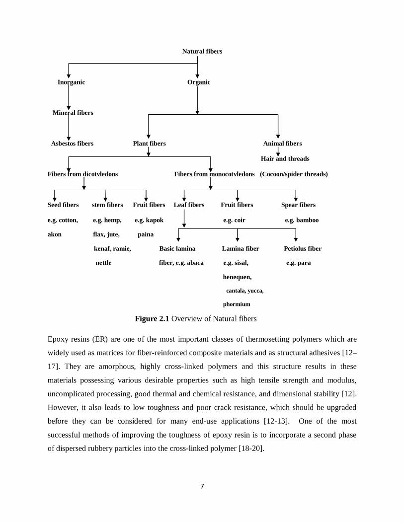
Natural fibers in general can be classified based on their origin, and the plant-based fibers
can be further categorized based on part of the plant they are recovered from. An overview of
natural fibers is presented in Figure-2.1 [11].
7
Natural fibers
Inorganic Organic
Mineral fibers
Asbestos fibers Plant fibers Animal fibers
Hair and threads
Fibers from dicotvledons Fibers from monocotvledons (Cocoon/spider threads)
Seed fibers stem fibers Fruit fibers Leaf fibers Fruit fibers Spear fibers
e.g. cotton, e.g. hemp, e.g. kapok e.g. coir e.g. bamboo
akon flax, jute, paina
kenaf, ramie, Basic lamina Lamina fiber Petiolus fiber
nettle fiber, e.g. abaca e.g. sisal, e.g. para
henequen,
cantala, yucca,
phormium
Figure 2.1 Overview of Natural fibers
Epoxy resins (ER) are one of the most important classes of thermosetting polymers which are
widely used as matrices for fiber-reinforced composite materials and as structural adhesives [12–
17]. They are amorphous, highly cross-linked polymers and this structure results in these
materials possessing various desirable properties such as high tensile strength and modulus,
uncomplicated processing, good thermal and chemical resistance, and dimensional stability [12].
However, it also leads to low toughness and poor crack resistance, which should be upgraded
before they can be considered for many end-use applications [12-13]. One of the most
successful methods of improving the toughness of epoxy resin is to incorporate a second phase
of dispersed rubbery particles into the cross-linked polymer [18-20].

8
Luo and Netravali [24] studied the tensile and flexural properties of the green composites
with different pineapple fiber content and compared with the virgin resin. Sisal fiber is fairly
coarse and inflexible. It has good strength, durability, ability to stretch, affinity for certain
dyestuffs, and resistance to deterioration in seawater. Sisal ropes and twines are widely used for
marine, agricultural, shipping, and general industrial use.
Belmeres et al. [25] found that sisal, henequen, and palm fiber have very similar physical,
chemical, and tensile properties. Cazaurang et al. [26] carried out a systematic study on the
properties of henequen fiber and pointed out that these fibers have mechanical properties that are
suitable for reinforcing thermoplastic resins.
Ahmed et al. [27] carried out research work on filament wound cotton fiber reinforced for
reinforcing high density polyethylene (HDPE) resin. Khalid et al. [28] also studied the use of
cotton fiber reinforced epoxy composites along with glass fiber reinforced polymers. Fuad et al.
[29] investigated the new type wood-based filler derived from oil palm wood flour (OPWF) for
bio-based thermoplastics composites by thermo gravimetric analysis and the results are very
promising.
Schneider and Karmaker [30] developed composites using jute and kenaf fiber and
polypropylene resins and they reported that jute fiber provides better mechanical properties than
kenaf fiber. During leaf defibration of heneque ´n fibres and also during the transformation of the
raw fibers into cordage, approximately 10% of waste fibres are produced. These waste fibers
could be profitably used in the manufacture of fiber polymer reinforced composites because they
posses attractive physical and mechanical properties [31].
2.2 Summary of the previous work done
The literature survey above reveals the following facts:
Plenty of work has been done on a number of natural fibers combining with polymer
matrices, resulting in improvement in mechanical properties of the composites compared with
the matrix material.

9
The major disadvantage of natural fiber reinforced composites is their property to absorb
moisture. Accordingly number of researches has been done to understand and improve this
quality of natural fiber reinforced composites.
Various studies have been done to understand the mechanical properties of different fibers
reinforced composites. However orange peel reinforced composite mechanical properties studies
have not been done so far.
2.3 Objectives of the Present Work
The objectives of the present work are:
To prepare the orange peel particulates of desired particle size.
To fabricate the particulate with different weight percentage in the epoxy matrix.
To study the density of different samples.
To check the micro-hardness of different samples.
To perform the tensile and flexural tests on the composite samples.
To conduct the SEM for the tensile and flexural tested samples to study the nature of
failure at the microscopic level.

10
CHAPTER 3
Materials and Method
3.1 Materials And Method
Raw materials used in this experimental work are listed below
1. Natural fiber (Orange peel)
2. Epoxy Resin
3. Hardener
3.1.1 Orange peel:
Orange is a citrus fruit mainly originated in Southeast Asia. It is the most commonly grown tree
fruit in the world. Like all citrus fruits, the orange is acidic having pH range 2.9-4.0.
Figure 3.1 (a) Orange peels
(b) Sun dried orange peels (c) Powdered orange peels
Orange peel, the outer cover part of an orange, mainly consists of cellulose, essential oils,
proteins and some simple carbohydrates.
The orange peels were collected locally and were sun dried for 5 days. Sun drying was necessary
to remove the moisture from the peels. The fibers were then grinded into fine powder as shown

11
in figure 3.2. The collected powders were sieved and a particle size distribution in a sample is
given in Table-3.1. Since the wt% of 212+ microns was around 74.6grams, for the present
investigation we have taken this particle size for further experimentation.
Table 3.1 Particles Size
Sample
No.
Size range
- micron
Size range
+ micron
Weight grams
approx.
Weight %
1.
------
1700
22.25
18.12
2. ------
212
74.60
67.16
3. 212
150
4.87
4.38
4. 150
106
4.17
3.75
5. 106
-----
5.18
4.66
Total 111.07
3.1.2 Epoxy Resin
The type of epoxy resin used in the present investigation is araldite LY556 which is
chemically belongs to epoxide family. Its common name is BisPhinol-A-Diglycidyl-Ether. It is
supplied by CIBA GUGYE India Limited.
3.1.3 Hardener
The hardener with IUPAC name NNO-bis (2aminoethylethane-1,2diamin) has been used
with epoxy designated as HY951. This has a viscosity of 10-20 MPa at 25ºC.

12
3.2. Composite preparation
A Per-pex sheet mould (dimension 130X100X6mm) figure-3.2 was used for casting the
composite sheet. A mould release spray was applied at the inner surface of the mould for quick
and easy release of the composite sheet. A calculated amount of epoxy resin and hardener (ratio
of 10:1 by weight) was taken and mixed with orange peel particulate with gentle stirring to
minimize air entrapment. After keeping the mould on a glass sheet (coated with wax) the mixture
is then poured into it. Care was taken to avoid formation of air bubbles. Pressure was then
applied from the top and the mould was allowed to cure at room temperature for 72 hrs. During
application of pressure some amount of epoxy and hardener squeezes out. Care has been taken to
consider this loss during manufacturing so that a constant thickness of sample could be
manufactured. This procedure was adopted for preparation of 5, 10, 20 and 30% weight fractions
of orange peel. After 72 hrs the samples were taken out of the mould, cut into different sizes and
kept in air tight container for further experimentation.
Figure 3.2 (a) Mould used for making the composite (b) Tensile test specimen
(c) Flexural test specimen

13
3.3 Experimental Procedure
The following tests were conducted on the samples:
a. Density measurement
b. Hardness test
c. Tensile test
d. Flexural test
3.3.1 Density Measurement
The density of composite materials in terms of volume fraction is found out from the
following equations
bw
ao
0
ctww
ws (3.1)
Where „„ρct‟ represents specific gravity of the composite,
W0 represents the weight of the sample; Wa represents the weight of the bottle + kerosene,
Wb represents the weight of the bottle + kerosene + sample,
Density of composite = Sct * density of kerosene. (3.2)
The theoretical density of composite materials in terms of weight fraction is found out
from the following equations as given by Agarwal and Broutman [32].
m
m
f
f
ct
ρ
W
ρ
W
1ρ (3.3)
Where „W’ and „ρ‟ represents the weight and density respectively. The suffix f, m and ct stand for
the fiber, matrix and the composite materials.
The void content of composite sample has been determined as per ASTM D-2734-70
standard procedure respectively. The volume fraction of voids (Vv) in the composites was
calculated by using equation:
14
t
atv
ρ
ρρV
(3.4)
where tρ and aρ are the theoretical and actual density of composite respectively
3.3.2 Hardness Test
Leitz Micro –hardness tester was used for Hardness measurement. This tester had a diamond
indentater, in the form a right pyramid with a square base and an angle 136° between opposite
faces, is forced in to the material under a load ranging from 0.3 to 3 N. Vickers hardness number
is calculated by using the following equations.
L = (X+Y)/2 (3.5.a)
Hv = 0.1889 F/L² (3.5)
Where „F‟ is the applied load, „L‟ is the diagonal of square impression (mm), „X‟ is the
horizontal length (mm), and „Y‟ is the vertical length (mm).
3.3.3 Tensile Test
The tension test is generally performed on flat specimens. The most commonly used specimen
geometries are the dog-bone specimen, figure-3.3, and straight-sided specimen with end tabs.
The standard test method as per ASTM D3039-76 has been used. The length of the test specimen
used is 150 mm. The tensile test is performed in universal testing machine (UTM). The tests
were performed with a cross head speed of 0.5mm/min. For each test composite of four samples
were tested and average value was taken for analysis. Figure 3.4(a, b) shows the machine used
for the test and the sample in loading condition.

15
Figure 3.3 Dog bone shape of the tensile testing sample
Figure 3.4 (a) UTM Machine Sample holder (b) UTM Machine Sample Loaded
3.3.4 Flexural Strength
The three point bend test was carried out in UTM machine in accordance with ASTM D2344-84
to measure the flexural strength of the composites. The loading arrangement for the specimen
and the photograph of the machine used are shown in Figure-3.5(a) and (b) respectively. The
entire specimens were of rectangular cross section of (150x20x5) mm. A span of 100 mm was

16
used for the test specimen. The specimens were tested at a crosshead speed of 0.5mm/min. The
flexural stress in a three point bending test is found out by using equation (3.6)
22
3
bt
FL (3.6)
Where F is the load, b is the width and t is the thickness of the specimen under test.
The short beam shear tests (SBS) are performed on the composite samples at room temperature
to evaluate the value of inter-laminar shear strength (ILSS). It is three point bending test which
generally promotes failure by inter-laminar shear. The SBS test is conducted as per ASTM
standard using the same UTM, span length 100mm and cross head speed 0.5mm/min.
The inter-laminar shear strength (ILSS) is found out by using the equation (3.7)
ILSS=tb
F
.4
3
(3.7)
Where F is the maximum load, b the width of the specimen and t is the thickness of the
specimen.
Figure 3.5(a) the loading arrangement for the flexural testing

17
Figure 3.5 (b) Flexural specimen loading position

18
CHAPTER 4
RESULTS AND DISCUSSION
4.1 Density Measurement
From the table 4.1 it is observed that the void fraction percentage of composite increases as the
percentage of reinforcement increases still the void content is very less so it shows that the
composite fabrication is done properly.
Figure 4.1 is drawn between the measured densities of the composites and weight fraction of the
composite. It is observed that as the reinforcement percentage increases in the epoxy the density
increases gradually up to 20 % and suddenly decreases at 30 % due to void percentage increases
the void content increase due to the weight percentage of fiber increases.
Table 4.1 Density of different Samples
Fiber content
(%)
Measured
Density
(gm/cm3 )
Theoretical
Density
(gm/cm3 )
Volume fraction
of voids (%)
0 1.082 1.100 1.636
5 1.0991
1.118918 1.7712
10 1.113 1.138498 2.239613
20 1.143 1.179788 3.118215
30 1.1398 1.224186 6.893266
Figure 4.1 The variation of density with different fiber contents
1.082
1.0991
1.113
1.143 1.1398
1.05
1.06
1.07
1.08
1.09
1.1
1.11
1.12
1.13
1.14
1.15
Neat Epoxy 5% 10% 20% 30%
De
nsi
ty
Weight fraction of orange peels

19
4.2 Hardness Test
Vickers hardness number is measured by Leitz Micro –hardness tester. The results are tabulated
in the table 4.2. Figure 4.2 drawn between the harness values of composite and the weight
percentage of composite. It is observed that as the reinforcement increases the hardness increases
the maximum value is obtained for composite prepared with the 20% composite.
Table 4.2 Hardness of different samples
Weight fraction of
particulates
(%)
Vicker Hardness value
Neat epoxy 17.894
5 18.28
10 19.68
20 20.72
30 18.95
Figure 4.2 Variation of Vicker Hardness value with different fiber contents
17.894
18.28
19.68
20.72
18.95
16
16.5
17
17.5
18
18.5
19
19.5
20
20.5
21
Neat Epoxy 5% 10% 20% 30%
Ha
rdn
ess
Weight fraction of orange peels

20
4.3 Tensile Test
The results of tensile test using UTM are tabulated in Table 4.3. From figure 4.3 it is observed
that the tensile strength is maximum for the composite prepared with 20% fiber However, for
30% fiber composite the tensile strength decreases because of the void content.
Table 4.3 Tensile Stress and Tensile Modulus of composites
Weight percent
of fiber Tensile Stress (MPa) Tensile Modulus (MPa)
Neat epoxy 18.031 648.23
5% 19.25 742.46
10% 22.69 1313.63
20% 25.85 1271.69
30% 21.34 938.96
Figure 4.3 Variation of Tensile strength with different fiber contents
18.031 19.25
22.69
25.85
21.34
0
5
10
15
20
25
30
Neat Epoxy 5% 10% 20% 30%
Ten
sile
str
engt
h M
pa
Weight fraction of orange peels
21
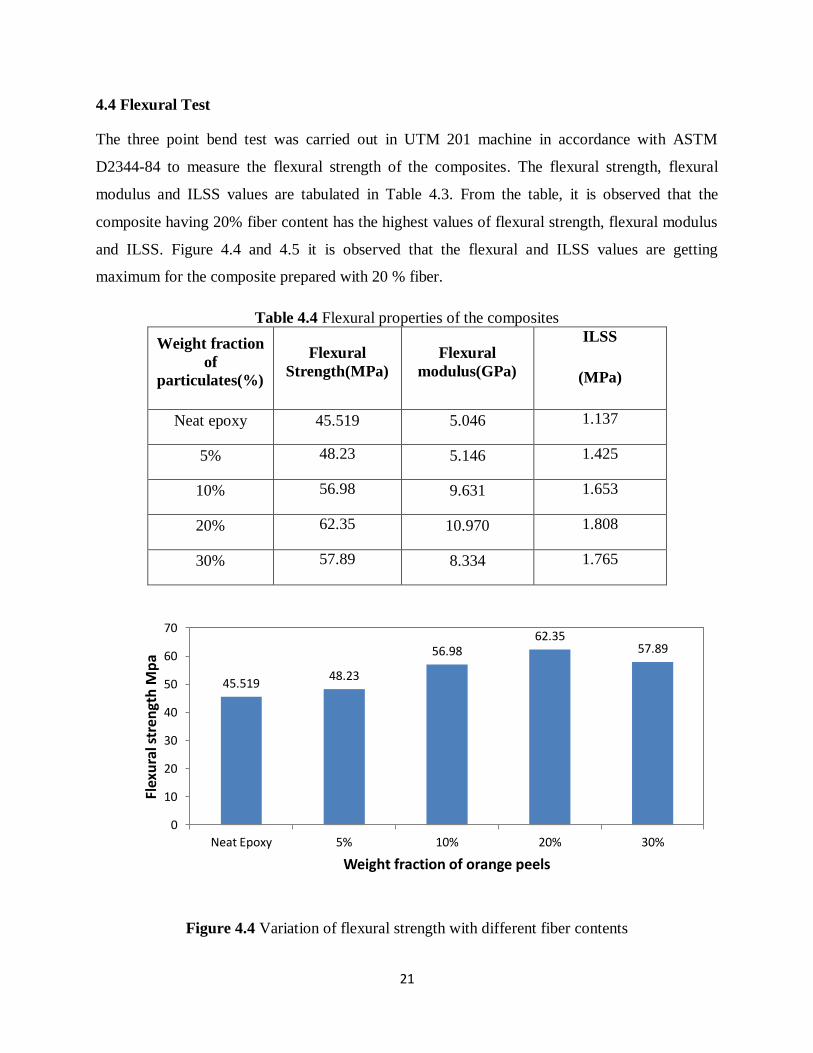
4.4 Flexural Test
The three point bend test was carried out in UTM 201 machine in accordance with ASTM
D2344-84 to measure the flexural strength of the composites. The flexural strength, flexural
modulus and ILSS values are tabulated in Table 4.3. From the table, it is observed that the
composite having 20% fiber content has the highest values of flexural strength, flexural modulus
and ILSS. Figure 4.4 and 4.5 it is observed that the flexural and ILSS values are getting
maximum for the composite prepared with 20 % fiber.
Table 4.4 Flexural properties of the composites
Weight fraction
of
particulates(%)
Flexural
Strength(MPa)
Flexural
modulus(GPa)
ILSS
(MPa)
Neat epoxy 45.519 5.046 1.137
5% 48.23 5.146 1.425
10% 56.98 9.631 1.653
20% 62.35 10.970 1.808
30% 57.89 8.334 1.765
Figure 4.4 Variation of flexural strength with different fiber contents
45.519 48.23
56.98 62.35
57.89
0
10
20
30
40
50
60
70
Neat Epoxy 5% 10% 20% 30%
Flex
ura
l str
engt
h M
pa
Weight fraction of orange peels

22
Figure 4.5 Variation of ILSS with different fiber contents
4.5 SEM Analysis
Scanning electron micrographs (SEM) of resin sample and its respective composites were taken
on Leo 435 VP. Figure 4.6 is the micro graphs of the 20 % orange peel reinforced epoxy
composite which is subjected to tensile test. Micrographs clearly show that no debonding, no
fiber chipping out and no crack formation it shows that the bonding is strong between the matrix
and reinforcement.
1.137
1.425
1.653 1.808 1.765
0
0.2
0.4
0.6
0.8
1
1.2
1.4
1.6
1.8
2
Neat Epoxy 5% 10% 20% 30%
ILSS
Weight fraction of orange peels

23
Figure 4.6 SEM micrograph of 20% orange peel composite after tensile test
Figure 4.7 SEM micrograph of 20% orange peel composite after flexural test
Figure 4.7 is the micro graphs of the 20 % orange peel reinforced epoxy composite which is
subjected to flexural strength micrographs clearly show that some bending of fibers are taken
place but the fibers are not come out from the epoxy it shows that the bonding is more between
the epoxy and orange peel fiber.

24
CHAPTER 5
5.1 CONCLUSIONS
The present work deals with the preparation of characterization of waste orange fiber reinforced
epoxy composite. The mechanical behavior of the composite lead to the following conclusions
1. With the successful fabrication of a new class of epoxy based composites reinforced with
orange fiber.
2. The flexural strength and ILSS of the composite is found to be maximum with 20%
weight percent of orange fiber.
3. The tensile strength of the composite is found to be maximum for the 20 % weight
percentage of the orange fiber.
4. The hardness value of the composite increases with increasing of the fiber content.
5. SEM observation reveals that most of the fibers were broken instead of pulling out from
the matrix. This indicates a good bonding between fiber and the matrix.
5.2 RECOMMENDATION FOR FURTHER RESEARCH
In this study fiber weight fraction of 30% has been used. This can be further increased to
higher weight fraction of fiber using other manufacturing methods.
The current study is limited to mechanical study only. It can be extended to tribological
tests.
The same work could be extended to different treated fiber composite.
25
REFERENCES
1. Herakovich, C.T., “Mechanics of fibrous composites”. New York: Wiley; (1998). p. 1–
27.
2. Berghezan, A.,” Nucleus”, 8(5), 1966, (Nucleus an Editeur, 1, rhe, Chalgrin, Paris,)
16(e).
3. Mallick P.K. 1993. Fiber Reinforced Composite: Materials, Manufacturing And Design,
Second Edition, 18, Marcel Dekker Inc, Newyork,
4. Abdul Khalil M., Abu Bakar A., Mariatti M., Jannah, H. P. S. 2008. Properties of
Banana and Pandanus Woven Fabric Reinforced Unsaturated, Polyester Composites,
Journal of Composite Materials, 42 (9), pp.931-941
5. Santos C.J.E. 2009. Development of Fiber Reinforced Composite for Structural
Applications, Submitted in partial fulfillment of course requirements for MatE 198B.
6. Rong, M.Z., Zhang, M.Q., Liu, Y., Yang, G.C. and Zeng, H.M., 2001, “The effect of
fiber treatment on the mechanical properties of unidirectional sisal-reinforced epoxy
composites,” Compos. Sci. Technol., 61; pp. 1437–1447.
7. Wambua P., Ivens J, Verpoest I., 2003, “Natural fibers: can they replace glass in fiber
reinforced plastics, Compos Science Technology”; 63: 1259–64.
8. Schuh TG., “Renewable materials for automotive applications”. Http // www. Ienica.
net / fibers seminar/schuh.pdf (Accessed in February 2006).
9. Khedari J., Charoemvai S., Hiruanlabh J., “New insulating particle boards from durian
peel and coconut coir. Build Environ”; 38: 2003, 435–441.
10. Bledzki A K., Gassan J., “Composites reinforced with cellulose based fibres”. Progress
in Polymer Science, Volume 24, (1999): p. 221-274.
11. Frank, R.R.,” Bast and other plant fibers”, 2005. Cambridge: woodhead publishing
limited.
26
12. Z. Zhikai, Z. Sixun, H. Jinyu C. Xingguo, G. Qipeng, and W. Jun, Phase Behavior and
Mechanical Properties of Epoxy Resin Containing Phenolphthalein Poly ether ether
Ketone, Journal of Polymer, 39 (5), (1997), pp. 1075–1080.
13. H. Shangjin, S. Keyu, B. Jie, Z. Zengkun, L. Liang, D. Zongjie and Z. Baolong, “Studies
on the Properties of Epoxy Resins Modified with Chain-Extended Ureas” , Journal of
Polymer, 42 (2001), pp. 9641–9647.
14. W. G. Potter, Epoxide Resins, New York: Springer, 1970.
15. C. A. May and G. Y. Tanaka, “Epoxy Resin Chemistry and Technology”. New York:
Marcel Dekker, 1973.
16. R. S. Bauer (ed.), “Epoxy Resin Chemistry I”, ACS Symposium Series, no. 114.
Washington, DC: American Chemical Society, 1979.
17. R. S. Bauer (ed.), “Epoxy Resin Chemistry II”, ACS Symposium Series, no. 201.
Washington, DC: American Chemical Society, 1983.
18. R. S. Drake, D. R. Egan, and W. T. Murphy in “Epoxy Resin Chemistry II”, (ed. R. S.
Bauer), ACS Symposium Series no. 221. Washington, DC: American Chemical Society,
1982, p. 1.
19. E. M. Yorkitis, in “Rubber-Modified Thermoset Resins”, (ed. K. Riew and J. K.
Gillham), Advances in Chemistry Series no. 208. Washington, DC: American Chemical
Society, 1984, p. 137.
20. J. S. Riffle, I. Yilgor, A. K. Banthia, C. Tran, G. L. Wilkes, and J. E. McGrath in “Epoxy
resin chemistry”, (ed. R. S. Bauer), ACS Symposium Series no. 201. Washington, DC:
American Chemical Society, 1983, p. 21.

27
21. C. B. Bucknall, Toughened Plastics, London: Applied Science, 1977.
22. P. A. Herrara-Franco, Valadez-Gonzalez, and M. Cervantes-uc, “Development and
Characterization of a HDPE–Sand–Natural Fiber Composite”, Composites Part B:
Engineering, 28B (3) 1997, pp. 331–343.
23. A, Maulida, M. Nasir, and H.P.S.A. Khalil, “Hybrid Composites Based on Natural
Fiber”, Proceedings of Symposium on Polymeric Materials, Penang, 1-2 June 2000,
(Published by USM Press, Penang, 2000), pp. 216–219.
24. S. Luo and A.N. Netravali, “Mechanical and Thermal Properties of Environmentally
Friendly “Green” Composites Made from Pineapple Leaf Fibers and Poly
(hydroxybutyrate-co-valerate) Resin”, Polymer Composites, 20 (3). (1999), pp. 367–378.
25. H. Belmares, A. Barrera, and M. Monjaras, “New Composite Materials from Natural
Hard fibers. Part 2. Fatigue Studies and a Novel Fatigue Degradation Model”, Industrial
Engineering Chemical Product Research and Development, 22 (1983), pp. 643–652.
26. M. Cazaurang, P. Herrera, I. Gonzalez, and V.M. Aguilar, “Physical and Mechanical
Properties of Henequen Fibers”, Journal of Applied Polymer Sciences, 43 (1991), pp.
749–756.
27. E.M. Ahmed, B. Sahari, and P. Pedersen, “Non Linear Behavior of Unidirectional
Filament Wound COTFRP, CFRP, and GFRP Composites”, Proceedings of World
Engineering Congress 1999, Mechanical and Manufacturing Engineering, Kuala Lumpur,
19–22 July, 1999, pp. 537–543.
28. A.A. Khalid, B. Sahari, and Y.A. Khalid, “Environmental Effects on the Progressive
Crushing of Cotton and Glass Fiber/Epoxy Composite Cones”, Proceedings of the
Fourth International Conference on Advances in Materials and Processing Technologies,
Kuala Lumpur, 24–28 August, 1998, pp. 680–689.

28
29. M.Y.A. Fuad, S. Rahmad, and M.R.N., Azlan, “Filler Content Determination of Bio-
Based Thermoplastics Composites by Thermogravimetric Analysis” Proceedings of the
Fourth International Conference on Advances in Materials and Processing Technologies,
Kuala Lumpur, 24–28 August, 1998, pp. 268–275.
30. J.P. Schneider, A.C. Karmaker, “Mechanical performance of short jute fiber reinforced
polypropylene”, J. Mater. Sc., 15, (1996), pp. 201-202.
31. Cazaurang-Martı ´nez MN, Herrera-Franco PJ, Gonza ´lez-Chi PI, Aguilar-Vega M.
Physical and mechanical properties of of henequen fibres. J Appl Polym Sci
1991;43:749–56.
32. Agarwal B.D., and Broutman L.J., “Analysis and performance of fiber composites” John
Wiley & Sons, New York, (1980): p. 3-12.