
Mechanical and electronic length measuring instruments for ...¤plin_hurtigtastere... · Ever since...
24
Mechanical and electronic length measuring instruments for internal and external measurements
Transcript of Mechanical and electronic length measuring instruments for ...¤plin_hurtigtastere... · Ever since...

Mechanical and electronic length measuring instruments for internal and external measurements

Ever since its foundation in1883 Kroeplin have beeninvolved in development andproduction of handy reliableand precise gauges for themeasurement of lengths andthicknesses, especially for themetalworking industry. Thusthe quick test system wascreated, which was the basisfor all further innovations andalso for the electronic dialindicators.
Experience is the solid founda-tion for quality. Carefulobservation and analysis of the market, flexible realization of requirements, convincing measuring concepts - that is the philosophy that makes Kroeplin successful. Today like before, for more than 125 years.
Certificate of quality
Reliable repeatability
Scales are well arranged and easy to read
Scale interval from 0,005mm up
Tolerance marks easy to read
All mechanical gauges are also available in “INCH”
The electronic gauges can be switched over to“INCH”
Measuring contacts are mainly made of carbide
Electronic gauges with analog / digital displayfor better reading
Mitutoyo interface
USB interface
Ergonomically designed
Measuring programs and contacts for differentapplications
Absolute and relative measurement
Red / Green LED for tolerance measurement
Special solutions possible
Stand holding unit for serial measurement ofsmall parts
Convincing price for convincing performance
■
■
■
■
■
■
■
■
■
■
■
■
■
■
■
■
■
■
Precision and continuity ContentsFeatures
Internal measurement
Application range up to 60mm
Application range up to 120mm
Application range exceeding 120mm
Internal comparison measurement
Internal measurement with 3-point contact
Internal measurement for blind holes
External measurement
Application range up to 30mm
Application range up to 200mm
Tube wall measurement
Application range up to 100mm
Measurement of foamed material and foils
Application range up to 100mm
Accessories / Interfaces
Special gauges / Definitions
4-5
6-7
8-9
10-11
12
14-15
16-17
18-19
20-21
22
23
13
Subject to technical alterations
Detailed information and data sheets for all gauges are available on our webpagewww.kroeplin.com

3
The established and proven
generation of Quicktests
■ IP 67■ optimized measuring force■ digital display with analog bar■ ergonomically designed■ Interfaces (USB, DIGIMATIC or U-WAVE)
available on request
Measuring contacts
■ easy handling
■ high repeatability
■ measuring programs and contacts for different applications
■ suitable for workshop use
■ IP 67
■ Interface (Digimatic, USB, U-WAVE®)
■ mm/inch switch
■ IP 65■ optimized measuring force■ accurate measurement■ ergonomically designed
■ fast reading
■ accurate measurement
■ precise measuring results
NEW!
Instruments with 3-point contact for easier centering
NEW !
Ergonomically designedwith new IP classification
The gauges provide a digital / analog display for better reading. The quicktest gauges includes custom designed test programs, measuring contacts, absolute- and relative measuring programs and red/green display for tolerance measurement.
electronic
mechanical

4Internal Measurement
Application range up to 60 mm
G102
G330
G210
H105
H210

Mea
suri
ng r
ange
Meb
Scal
e in
terv
al S
kw
Perm
issi
ble
erro
rs G
Repe
atab
ility
lim
it r
Mea
suri
ng fo
rce
min
.
Mea
suri
ng fo
rce
max
.
Elec
tron
ic E
Mec
hani
cal M
Mea
suri
ng c
onta
ctm
ovab
le H
b
Mea
suri
ng c
onta
ctfix
ed H
f
Type
of m
easu
ring
cont
act
Mea
suri
ng s
pan
Mes
Rang
e of
indi
catio
n Az
b
Wei
ght
Prot
ectio
n cl
ass
Type [mm] [mm] [mm] [mm] [mm] [mm] [mm] [mm] [mm][N] [g][N]
Measuring contacts Measuring capacity5
[mm]
Woo
den
box
Pict
ure
Mea
suri
ng d
epth
L m
ax.
Groo
ve d
epth
A
Groo
ve w
idth
B
[mm][mm]
Meb Measuring rangeA Groove depthB Groove width
Hb Measuring contact movableHf Measuring contact fixedL Measuring depth
Type [mm] [mm] [mm] [mm] [mm] [mm] [mm] [mm] [mm][N] [g][N] [mm][mm][mm]
Mea
suri
ng r
ange
Meb
Scal
e in
terv
al S
kw
Perm
issi
ble
erro
rs G
Repe
atab
ility
lim
it r
Mea
suri
ng fo
rce
min
.
Mea
suri
ng fo
rce
max
.
Elec
tron
ic E
M
echa
nica
l M
Mea
suri
ng c
onta
ctm
ovab
le H
b
Mea
suri
ng c
onta
ctfix
ed H
f
Type
of m
easu
ring
cont
act
Mea
suri
ng s
pan
Mes
Rang
e of
indi
catio
n Az
b
Wei
ght
Prot
ectio
n cl
ass
Woo
den
box
Pict
ure
Mea
suri
ng d
epth
L m
ax.
Groo
ve d
epth
A m
ax.
Groo
ve w
idth
B m
in.
Chisel R 0,1
Chisel R 0,1
Ball Ø0,6
Ball Ø0,6
Ball Ø1
Ball Ø1
Ball Ø1
Ball Ø1
Ball Ø1
Ball Ø1
Ball Ø1
Ball Ø1
Ball Ø1,3
Ball Ø1,5
10
10
10
10
20
20
20
20
20
20
20
20
30
30
G102
H102
G105
H105
G210
H210
G220
H220
G230
H230
G240
H240
G313
G330
2,5 - 12,5
2,5 - 12,5
5 - 15
5 - 15
10 - 30
10 - 30
20 - 40
20 - 40
30 - 50
30 - 50
40 - 60
40 - 60
13 - 43
30 - 60
0,005
0,005
0,005
0,005
0,01
0,01
0,01
0,01
0,01
0,01
0,01
0,01
0,02
0,02
1,2
1,2
1,2
1,2
1,6
1,6
1,6
1,6
1,6
1,6
1,6
1,6
1,7
1,7
E
M
E
M
E
M
E
M
E
M
E
M
E
E
0,7
0,7
2,3
2,3
5,2
5,2
7,0
7,0
7,0
7,0
8,3
8,3
5,7
6,2
0,9
0,9
2,5
2,5
5,3
5,3
7,3
7,3
7,3
7,3
8,5
8,5
5,7
6,5
0,9
0,9
2,5
2,5
5,3
5,3
7,3
7,3
7,3
7,3
8,5
8,5
5,7
6,5
[1]
[1]
[2]
[2]
[2]
[2]
[4]
[4]
[4]
[4]
[5]
[5]
[2]
[5]
2,4 - 12,8
2,4 - 12,8
4,7 - 15,3
4,7 - 15,3
9,5 - 30,5
9,5 - 30,5
19,5 - 40,5
19,5 - 40,5
29,5 - 50,5
29,5 - 50,5
39,5 - 60,5
39,5 - 60,5
12,5 - 43,5
29,5 - 60,5
225
155
230
160
250
180
250
180
255
185
265
195
360
370
IP67
IP65
IP67
IP65
IP67
IP65
IP67
IP65
IP67
IP65
IP67
IP65
IP67
IP67
1732-45
1732-45
1732-45
1732-45
1732-45
1732-45
1732-45
1732-45
1732-45
1732-45
1732-45
1732-45
1732-51
1732-51
0,015
0,015
0,015
0,015
0,03
0,03
0,03
0,03
0,03
0,03
0,03
0,03
0,04
0,04
0,005
0,005
0,005
0,005
0,01
0,01
0,01
0,01
0,01
0,01
0,01
0,01
0,02
0,02
0,8
0,8
0,8
0,8
1,1
1,1
1,1
1,1
1,1
1,1
1,1
1,1
1,2
1,2
0,5
0,5
0,8
0,8
1,2
1,2
1,2
1,2
1,2
1,2
1,2
1,2
1,6
1,8
12
12
35
35
85
85
85
85
85
85
85
85
127
132
Chisel R 0,1 mm Ball Ø 0,6 mmBall Ø 1,0 mmBall Ø 1,3 mm
Ball Ø 1,0 mm Ball Ø 1,0 mmBall Ø 1,5 mmBall Ø 2,0 mm
[5][4][2][1]

6Internal Measurement
Application range up to 120 mm
G240
G415
G370
H240
H415
H470

Measuring contacts Measuring capacity7
Hb Measuring contact movableHf Measuring contact fixedL Measuring depth
Meb Measuring rangeA Groove depthB Groove width
Type [mm] [mm] [mm] [mm] [mm] [mm] [mm] [mm] [mm][N] [g][N] [mm][mm][mm]
Mea
suri
ng r
ange
Meb
Scal
e in
terv
al S
kw
Perm
issi
ble
erro
rs G
Repe
atab
ility
lim
it r
Mea
suri
ng fo
rce
min
.
Mea
suri
ng fo
rce
max
.
Elec
tron
ic E
M
echa
nica
l M
Mea
suri
ng c
onta
ctm
ovab
le H
b
Mea
suri
ng c
onta
ctfix
ed H
f
Type
of m
easu
ring
cont
act
Mea
suri
ng s
pan
Mes
Rang
e of
indi
catio
n Az
b
Wei
ght
Prot
ectio
n cl
ass
Woo
den
box
Pict
ure
Mea
suri
ng d
epth
L m
ax.
Groo
ve d
epth
A m
ax.
Groo
ve w
idth
B m
in.
Ball Ø1
Ball Ø1
Ball Ø1
Ball Ø1
Ball Ø1
Ball Ø1
Ball Ø1
Ball Ø1
Ball Ø2
Ball Ø2
Ball Ø2
Ball Ø1,5
Ball Ø1,5
Ball Ø2
Ball Ø2
Ball Ø2
Ball Ø2
20
20
20
20
20
20
20
20
30
30
30
50
50
50
50
50
50
50 - 70
50 - 70
60 - 80
60 - 80
70 - 90
70 - 90
80 - 100
80 - 100
50 - 80
70 - 100
90 - 120
15 - 65
15 - 65
40 - 90
40 - 90
70 - 120
70 - 120
0,01
0,01
0,01
0,01
0,01
0,01
0,01
0,01
0,02
0,02
0,02
0,02
0,05
0,02
0,05
0,02
0,05
1,6
1,6
1,6
1,6
1,6
1,6
1,6
1,6
1,7
1,7
1,7
1,8
1,9
1,8
1,9
1,8
1,9
E
M
E
M
E
M
E
M
E
E
E
E
M
E
M
E
M
8,3
8,3
8,3
8,3
8,3
8,3
8,3
8,3
8,3
8,3
8,3
5,5
5,5
8,3
8,3
8,3
8,3
8,5
8,5
8,5
8,5
8,5
8,5
8,5
8,5
8,5
8,5
8,5
6,0
6,0
8,5
8,5
8,5
8,5
8,5
8,5
8,5
8,5
8,5
8,5
8,5
8,5
8,5
8,5
8,5
6,0
6,0
8,5
8,5
8,5
8,5
[5]
[5]
[5]
[5]
[5]
[5]
[5]
[5]
[5]
[5]
[3]
[3]
[5]
[5]
[5]
[5]
[5]
49,5 - 70,5
49,5 - 70,5
59,5 - 80,5
59,5 - 80,5
69,5 - 90,5
69,5 - 90,5
79,5 - 100,5
79,5 - 100,5
49,5 - 80,5
69,5 - 100,5
89,5 - 120,5
14,5 - 65,5
14,5 - 65,5
39,5 - 90,5
39,5 - 90,5
69,5 - 120,5
69,5 - 120,5
265
195
270
200
270
200
270
200
370
375
380
415
355
420
370
420
370
IP67
IP65
IP67
IP65
IP67
IP65
IP67
IP65
IP67
IP67
IP67
IP67
IP65
IP67
IP65
IP67
IP65
1732-45
1732-45
1732-45
1732-45
1732-45
1732-45
1732-45
1732-45
1732-51
1732-51
1732-51
1732-51
1732-51
1732-51
1732-51
1732-51
1732-51
0,03
0,03
0,03
0,03
0,03
0,03
0,03
0,03
0,04
0,04
0,04
0,06
0,05
0,06
0,05
0,06
0,05
0,01
0,01
0,01
0,01
0,01
0,01
0,01
0,01
0,02
0,02
0,02
0,04
0,025
0,04
0,025
0,04
0,025
1,1
1,1
1,1
1,1
1,1
1,1
1,1
1,1
1,2
1,2
1,2
1,0
0,9
1,0
0,9
1,0
0,9
1,2
1,2
1,2
1,2
1,2
1,2
1,2
1,2
2,4
2,4
2,4
1,9
1,9
2,4
2,4
2,4
2,4
85
85
85
85
85
85
85
85
132
132
132
188
188
192
192
192
192
Ball Ø 1,0 mmBall Ø 1,5 mm
Ball Ø 1,0 mmBall Ø 2,0 mm
[5][3]
G250
H250
G260
H260
G270
H270
G280
H280
G350
G370
G390
G415
H415
G440
H440
G470
H470

8
Application range up to 120 mm
Internal Measurement
H4100
ID80200
G4100
H870G850

Measuring contacts Measuring capacity9
Meb Measuring rangeA Groove depthB Groove width
Hb Measuring contact movableHf Measuring contact fixedL Measuring depth
Type [mm] [mm] [mm] [mm] [mm] [mm] [mm] [mm] [mm][N] [g][N] [mm][mm][mm]
Mea
suri
ng r
ange
Meb
Scal
e in
terv
al S
kw
Perm
issi
ble
erro
rs G
Repe
atab
ility
lim
it r
Mea
suri
ng fo
rce
min
.
Mea
suri
ng fo
rce
max
.
Elec
tron
ic E
M
echa
nica
l M
Mea
suri
ng c
onta
ctm
ovab
le H
b
Mea
suri
ng c
onta
ctfix
ed H
f
Type
of m
easu
ring
cont
act
Mea
suri
ng s
pan
Mes
Rang
e of
indi
catio
n Az
b
Wei
ght
Prot
ectio
n cl
ass
Woo
den
box
Pict
ure
Mea
suri
ng d
epth
L m
ax.
Groo
ve d
epth
A m
ax.
Groo
ve w
idth
B m
in.
Ball Ø 2,0 mm Ball Ø 5,0 mm Ball Ø 5,0 mm Hemisphere SR 20 mm
[20][19][18][5]
Ball Ø2
Ball Ø2
Ball Ø2
Ball Ø2
Ball Ø2
Ball Ø2
Ball Ø5
Ball Ø5
Ball Ø5
Ball Ø5
Ball Ø5
Ball Ø5
Ball Ø5
Hemisphere SR 20
50
50
50
50
50
50
100
100
100
100
100
100
100
200
G4100
H4100
G4130
H4130
G4150
H4150
G850
H850
G870
H870
ID6080
ID60150
ID60220
ID80200
100 - 150
100 - 150
130 - 180
130 - 180
150 - 200
150 - 200
50 - 150
50 - 150
70 - 170
70 - 170
80 - 180
150 - 250
220 - 320
200 - 400
0,02
0,05
0,02
0,05
0,02
0,05
0,05
0,1
0,05
0,1
0,1
0,1
0,1
0,2
1,8
1,9
1,8
1,9
1,8
1,9
2,0
2,0
2,0
2,0
2,5
2,5
2,5
2,0
E
M
E
M
E
M
E
M
E
M
M
M
M
M
8,3
8,3
8,3
8,3
8,3
8,3
3,0
3,0
13,0
13,0
11,0
31,0
31,0
28,0
8,5
8,5
8,5
8,5
8,5
8,5
4,0
4,0
14,0
14,0
12,0
32,0
32,0
29,0
8,5
8,5
8,5
8,5
8,5
8,5
4,0
4,0
14,0
14,0
12,0
32,0
32,0
29,0
[5]
[5]
[5]
[5]
[5]
[5]
[18]
[18]
[19]
[19]
[19]
[19]
[19]
[20]
99,5 - 150,5
99,5 - 150,5
129,5 - 180,5
129,5 - 180,5
149,5 - 200,5
149,5 - 200,5
49,5 - 150,5
49,5 - 150,5
69,5 - 170,5
69,5 - 170,5
79,5 - 180,5
149,5 - 250,5
219,5 - 320,5
199,5 - 400,5
425
385
430
390
435
395
650
590
650
590
1600
1600
1700
2200
IP67
IP65
IP67
IP65
IP67
IP65
IP67
IP65
IP67
IP65
-
-
-
-
1732-51
1732-51
HK
HK
HK
HK
HK
HK
HK
HK
HK
HK
HK
HK
0,06
0,05
0,06
0,05
0,06
0,05
0,15
0,15
0,15
0,15
0,25
0,3
0,3
0,4
0,04
0,025
0,04
0,025
0,04
0,025
0,1
0,1
0,1
0,1
0,1
0,1
0,1
0,2
1,0
0,9
1,0
0,9
1,0
0,9
0,8
0,8
0,8
0,8
1,5
1,5
1,5
1,0
2,4
2,4
2,4
2,4
2,4
2,4
5,5
5,5
5,5
5,5
5,5
5,5
5,5
21,0
192
192
192
192
192
192
395
395
395
395
535
535
535
735

10
Application range from 50 mm to 430 mm
Internal Comparison Measurement
H4M180 H2M50
H2M90

Measuring contacts Measuring capacity11
Hb Measuring contact movableHf Measuring contact fixedL Measuring depth
Meb Measuring rangeA Groove depthB Groove width
Type [mm] [mm] [mm] [mm] [mm] [mm] [mm] [mm] [mm][N] [g][N] [mm]
Mea
suri
ng r
ange
Meb
Scal
e in
terv
al S
kw
Perm
issi
ble
erro
rs G
Repe
atab
ility
lim
it r
Mea
suri
ng fo
rce
min
.
Mea
suri
ng fo
rce
max
.
Elec
tron
ic E
M
echa
nica
l M
Mea
suri
ng c
onta
ctm
ovab
le H
b
Mea
suri
ng c
onta
ctfix
ed H
f
Type
of m
easu
ring
cont
act
Mea
suri
ng s
pan
Mes
Rang
e of
indi
catio
n Az
b
Wei
ght
Prot
ectio
n cl
ass
Woo
den
box
Pict
ure
Mea
suri
ng d
epth
L m
ax.
Groo
ve d
epth
A m
ax.
Groo
ve w
idth
B m
in.
[mm][mm]
[5]
Ball Ø1
Ball Ø1
Ball Ø1
Ball Ø2
Ball Ø2
20
20
20
50
50
H2M50
H2M90
H2M130
H4M180
H4M300
50 - 100
90 - 140
130 - 180
180 - 310
300 - 430
0,01
0,01
0,01
0,05
0,05
1,6
1,6
1,6
1,9
1,9
M
M
M
M
M
8,3
8,3
8,3
8,3
8,3
12,0
12,0
12,0
21,0
21,0
variable
variable
variable
variable
variable
[5]
[5]
[5]
[5]
[5]
49,5 - 100,5
89,5 - 140,5
129,5 - 180,5
179,5 -310,5
299,5 - 430,5
220
230
240
420
450
IP65
IP65
IP65
IP65
IP65
HK
HK
HK
HK
HK
0,03
0,03
0,03
0,10
0,15
0,015
0,015
0,015
0,05
0,05
1,1
1,1
1,1
0,9
0,9
1,2
1,2
1,2
2,2
2,2
85
85
85
170
170
Ball Ø 1,0 mmBall Ø 2,0 mm

Type [mm] [mm] [mm] [mm] [mm] [mm] [mm] [mm] [mm] [mm][N] [g][N] [mm]
Ball Ø0,6
Ball Ø1
Ball Ø1
Ball Ø1
Ball Ø1
Ball Ø1
Ball Ø1
Ball Ø1
7
10
15
20
20
20
20
20
G107P3
G210P3
G215P3
G225P3
G240P3
G255P3
G270P3
G285P3
7 - 14
10 - 20
15 - 30
25 - 45
40 - 60
55 - 75
70 - 90
85 - 105
0,002
0,005
0,005
0,005
0,005
0,005
0,005
0,005
1,4
1,6
1,6
1,6
1,6
1,6
1,6
1,6
E
E
E
E
E
E
E
E
34
75
77
84
84
84
84
84
2,2
3,5
5,0
7,0
8,0
8,0
8,5
9,0
0,8
1,6
1,6
1,6
1,6
1,6
1,6
1,6
2,5
4,6
5,8
7,3
12,2
12,2
12,2
12,2
-
-
-
-
-
-
-
-
[1]
[2]
[2]
[3]
[3]
[3]
[3]
[3]
6,8 - 14,5
9,8 - 20,5
14,5 - 30,5
24,5 - 45,5
39,5 - 60,5
54,5 - 75,5
69,5 - 91
84,5 - 106
230
250
275
255
270
270
275
285
IP67
IP67
IP67
IP67
IP67
IP67
IP67
IP67
0,01
0,02
0,02
0,02
0,02
0,02
0,02
0,02
0,004
0,01
0,01
0,01
0,01
0,01
0,01
0,01
1,0
1,1
1,1
1,1
1,1
1,1
1,1
1,1
1732-45
1732-45
1732-45
1732-45
1732-45
1732-45
1732-45
1732-45
[mm] [mm]
Mea
suri
ng r
ange
Meb
Perm
issi
ble
erro
rs G
Repe
atab
ility
lim
it r
Mea
suri
ng fo
rce
min
.
Mea
suri
ng fo
rce
max
.
Mea
suri
ng c
onta
ct
mov
able
Hb
Mea
suri
ng c
onta
ct
mov
able
Hf
Type
of m
easu
ring
co
ntac
t
Mea
suri
ng s
pan
Mes
Rang
e of
indi
catio
n Az
b
Wei
ght
Prot
ectio
n cl
ass
Woo
den
box
Pict
ure
Mea
suri
ng d
epth
L m
ax.
Num
eric
al in
terv
al Z
w
Groo
ve d
epth
A m
ax.
Groo
ve w
idth
B m
in.
Mec
hani
cal M
Elec
tron
ic E
Internal measurement with 3-point contact
Measuring contacts
Ball Ø 1,0 mm Ball Ø 1,0 mmBall Ø 0,6 mm
12
G210P3
Application range from 7 mm to 105 mm
[2][1] [3]
Hb Measuring contact movableHf Measuring contact fixedL Measuring depth
Meb Measuring rangeA Groove depthB Groove width
Measuring capacity

Type [mm] [mm] [mm] [mm] [mm] [mm] [mm] [mm][mm][N] [g][N] Accessories[mm]
Conus SR = 0,2
Conus SR = 0,2
Conus SR = 0,2
Conus SR = 0,2
Conus SR = 0,2
Conus SR = 0,2
Conus SR = 0,2
Conus SR = 0,2
20
20
20
20
20
20
20
20
G2G20
H2G20
G2G30
H2G30
G2G40
H2G40
G2G50
H2G50
20 - 40
20 - 40
30 - 50
30 - 50
40 - 60
40 - 60
50 - 70
50 - 70
0,01
0,01
0,01
0,01
0,01
0,01
0,01
0,01
1,6
1,6
1,6
1,6
1,6
1,6
1,6
1,6
E
M
E
M
E
M
E
M
85
85
85
85
85
85
85
85
Ø 1,6
Ø 1,6
Ø 1,6
Ø 1,6
Ø 1,6
Ø 1,6
Ø 1,6
Ø 1,6
5,0
5,0
5,0
5,0
5,0
5,0
5,0
5,0
5,0
5,0
5,0
5,0
5,0
5,0
5,0
5,0
[13]
[13]
[13]
[13]
[13]
[13]
[13]
[13]
19,5 - 40,5
19,5 - 40,5
29,5 - 50,5
29,5 - 50,5
39,5 - 60,5
39,5 - 60,5
49,5 - 70,5
49,5 - 70,5
250
180
255
185
265
195
265
195
IP67
IP65
IP67
IP65
IP67
IP65
IP67
IP65
0,03
0,03
0,03
0,03
0,03
0,03
0,03
0,03
0,01
0,01
0,01
0,01
0,01
0,01
0,01
0,01
1,1
1,1
1,1
1,1
1,1
1,1
1,1
1,1
1732-45
1732-45
1732-45
1732-45
1732-45
1732-45
1732-45
1732-45
[mm]
Internal measurement for blind holes
Conus SR 0,2 mm
13
Application range from 20 mm to 70 mm
Further measuring ranges available on request
H2G40
[13]
Mea
suri
ng r
ange
Meb
Perm
issi
ble
erro
rs G
Repe
atab
ility
lim
it r
Mea
suri
ng fo
rce
min
.
Mea
suri
ng fo
rce
max
.
Mea
suri
ng c
onta
ct
mov
able
Hb
Mea
suri
ng c
onta
ct
mov
able
Hf
Type
of m
easu
ring
co
ntac
t
Mea
suri
ng s
pan
Mes
Rang
e of
indi
catio
n Az
b
Wei
ght
Prot
ectio
n cl
ass
Woo
den
box
Pict
ure
Mea
suri
ng d
epth
L m
ax.
Num
eric
al in
terv
al Z
w
max
. Mea
suri
ng
cont
act t
hick
ness
Mec
hani
cal M
Elec
tron
ic E
Measuring capacityMeasuring contacts Measuring capacity
Hb Measuring contact movableHf Measuring contact fixedL Measuring depth

14
Application range up to 30 mm
External measurement
POCO2K
C330
C220 D220
D110C110

15
Mea
suri
ng r
ange
Meb
Scal
e in
terv
al S
kw
Perm
issi
ble
erro
rs G
Repe
atab
ility
lim
it r
Mea
suri
ng fo
rce
min
.
Mea
suri
ng fo
rce
max
.
Elec
tron
ic E
Mec
hani
cal M
Mea
suri
ng c
onta
ct
mov
able
Hb
Mea
suri
ng c
onta
ct
fixed
Hf
Type
of m
easu
ring
co
ntac
t
Mea
suri
ng s
pan
Mes
Rang
e of
indi
catio
n Az
b
Wei
ght
Prot
ectio
n cl
ass
Woo
den
box
Pict
ure
Mea
suri
ng d
epth
L
max
.
Type [mm] [mm] [mm] [mm] [mm] [mm] [mm] [mm] [mm][N] [g][N] [mm]
Mea
suri
ng r
ange
Meb
Scal
e in
terv
al S
kw
Perm
issi
ble
erro
rs G
Repe
atab
ility
lim
it r
Mea
suri
ng fo
rce
min
.
Mea
suri
ng fo
rce
max
.
Elec
tron
ic E
Mec
hani
cal M
Mea
suri
ng c
onta
ct
mov
able
Hb
Mea
suri
ng c
onta
ct
fixed
Hf
Type
of m
easu
ring
co
ntac
t
Mea
suri
ng s
pan
Mes
Rang
e of
indi
catio
n Az
b
Wei
ght
Prot
ectio
n cl
ass
Woo
den
box
Pict
ure
Mea
suri
ng d
epth
L
max
.
Measuring capacityMeasuring contacts Measuring capacity
Ball Ø 1,5 mmBall Ø 3,0 mm
Chisel R 0,4 mmChisel R 0,75 mm
Ball Ø 5,0 mm Needle Ø 0,75 mm Chisel R 0,5 mmPlane Ø 3,5 mm
[25][24][23][7][6]
Ball Ø5
Needle Ø 0,75
Sn-R 0,5 / F Ø3,5
Ball Ø1,5
Ball Ø1,5
Chisel R 0,4
Chisel R 0,4
Ball Ø1,5
Ball Ø1,5
Chisel R 0,4
Chisel R 0,4
Ball Ø3
Chisel R 0,75
10
10
10
10
10
10
10
20
20
20
20
30
30
POCO 2K
POCO 2N
POCO 2F
C110
D110
C110S
D110S
C220
D220
C220S
D220S
C330
C330S
0 - 10
0 - 10
0 - 10
0 - 10
0 - 10
0 - 10
0 - 10
0 - 20
0 - 20
0 - 20
0 - 20
0 - 30
0 - 30
0,1
0,1
0,1
0,005
0,005
0,005
0,005
0,01
0,01
0,01
0,01
0,02
0,02
1,3
1,3
1,3
1,2
1,2
1,2
1,2
1,6
1,6
1,6
1,6
1,6
1,6
M
M
M
E
M
E
M
E
M
E
M
E
E
36
36
36
35
35
35
35
85
85
85
85
116
116
5
3,5
4,5
19,1
19,1
18,8
18,8
24,7
24,7
24,7
24,7
30
30
5
3,5
4,5
18,6
18,6
18,5
18,5
24,6
24,6
24,6
24,6
30
30
[23]
[24]
[25]
[6]
[6]
[7]
[7]
[6]
[6]
[7]
[7]
[6]
[7]
0 - >10
0 - >10
0 - >10
0 - 10,5
0 - 10,5
0 - 10,5
0 - 10,5
0 - 20,5
0 - 20,5
0 - 20,5
0 - 20,5
0 - 30,5
0 - 30,5
40
40
40
240
170
240
170
280
210
280
210
430
430
-
-
-
IP67
IP65
IP67
IP65
IP67
IP65
IP67
IP65
IP67
IP67
1732-01
1732-01
1732-01
1732-45
1732-45
1732-45
1732-45
1732-45
1732-45
1732-45
1732-45
1732-51
1732-51
0,1
0,1
0,1
0,015
0,015
0,015
0,015
0,03
0,03
0,03
0,03
0,04
0,04
0,05
0,05
0,05
0,005
0,005
0,005
0,005
0,01
0,01
0,01
0,01
0,02
0,02
0,3
0,3
0,3
0,8
0,8
0,8
0,8
1,1
1,1
1,1
1,1
0,9
0,9
Hb Measuring contact movableHf Measuring contact fixedL Measuring depth

16
D450
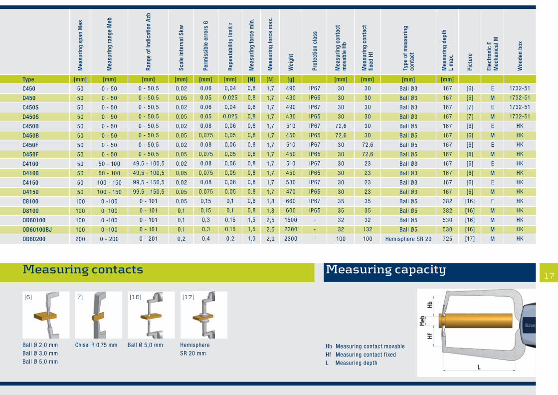
Application range up to 200 mm
External Measurement
OD60100BJ
D450F
C450
C8100
17
Mea
suri
ng r
ange
Meb
Scal
e in
terv
al S
kw
Perm
issi
ble
erro
rs G
Repe
atab
ility
lim
it r
Mea
suri
ng fo
rce
min
.
Mea
suri
ng fo
rce
max
.
Elec
tron
ic E
Mec
hani
cal M
Mea
suri
ng c
onta
ct
mov
able
Hb
Mea
suri
ng c
onta
ct
fixed
Hf
Type
of m
easu
ring
co
ntac
t
Mea
suri
ng s
pan
Mes
Rang
e of
indi
catio
n Az
b
Wei
ght
Prot
ectio
n cl
ass
Woo
den
box
Pict
ure
Mea
suri
ng d
epth
L
max
.
Type [mm] [mm] [mm] [mm] [mm] [mm] [mm] [mm] [mm][N] [g][N] [mm]
Mea
suri
ng r
ange
Meb
Scal
e in
terv
al S
kw
Perm
issi
ble
erro
rs G
Repe
atab
ility
lim
it r
Mea
suri
ng fo
rce
min
.
Mea
suri
ng fo
rce
max
.
Elec
tron
ic E
Mec
hani
cal M
Mea
suri
ng c
onta
ct
mov
able
Hb
Mea
suri
ng c
onta
ct
fixed
Hf
Type
of m
easu
ring
co
ntac
t
Mea
suri
ng s
pan
Mes
Rang
e of
indi
catio
n Az
b
Wei
ght
Prot
ectio
n cl
ass
Woo
den
box
Pict
ure
Mea
suri
ng d
epth
L
max
.
Measuring capacityMeasuring contacts Measuring capacity
Ball Ø 2,0 mmBall Ø 3,0 mmBall Ø 5,0 mm
Chisel R 0,75 mm Ball Ø 5,0 mm Hemisphere SR 20 mm
[17][16]7][6]
Ball Ø3
Ball Ø3
Ball Ø3
Ball Ø3
Ball Ø5
Ball Ø5
Ball Ø5
Ball Ø5
Ball Ø3
Ball Ø3
Ball Ø3
Ball Ø3
Ball Ø5
Ball Ø5
Ball Ø5
Ball Ø5
Hemisphere SR 20
50
50
50
50
50
50
50
50
50
50
50
50
100
100
100
100
200
C450
D450
C450S
D450S
C450B
D450B
C450F
D450F
C4100
D4100
C4150
D4150
C8100
D8100
OD60100
OD60100BJ
OD80200
0 - 50
0 - 50
0 - 50
0 - 50
0 - 50
0 - 50
0 - 50
0 - 50
50 - 100
50 - 100
100 - 150
100 - 150
0 -100
0 -100
0 -100
0 -100
0 - 200
0,02
0,05
0,02
0,05
0,02
0,05
0,02
0,05
0,02
0,05
0,02
0,05
0,05
0,1
0,1
0,1
0,2
1,7
1,7
1,7
1,7
1,7
1,7
1,7
1,7
1,7
1,7
1,7
1,7
1,8
1,8
2,5
2,5
2,0
E
M
E
M
E
M
E
M
E
M
E
M
E
M
M
M
M
167
167
167
167
167
167
167
167
167
167
167
167
382
382
530
530
725
30
30
30
30
72,6
72,6
30
30
30
30
30
30
35
35
32
32
100
30
30
30
30
30
30
72,6
72,6
23
23
23
23
35
35
32
132
100
[6]
[6]
[7]
[7]
[6]
[6]
[6]
[6]
[6]
[6]
[6]
[6]
[16]
[16]
[16]
[16]
[17]
0 - 50,5
0 - 50,5
0 - 50,5
0 - 50,5
0 - 50,5
0 - 50,5
0 - 50,5
0 - 50,5
49,5 - 100,5
49,5 - 100,5
99,5 - 150,5
99,5 - 150,5
0 - 101
0 - 101
0 - 101
0 - 101
0 - 201
490
430
490
430
510
450
510
450
510
450
530
470
660
600
1500
2300
2300
IP67
IP65
IP67
IP65
IP67
IP65
IP67
IP65
IP67
IP65
IP67
IP65
IP67
IP65
-
-
-
1732-51
1732-51
1732-51
1732-51
HK
HK
HK
HK
HK
HK
HK
HK
HK
HK
HK
HK
HK
0,06
0,05
0,06
0,05
0,08
0,075
0,08
0,075
0,08
0,075
0,08
0,075
0,15
0,15
0,3
0,3
0,4
0,04
0,025
0,04
0,025
0,06
0,05
0,06
0,05
0,06
0,05
0,06
0,05
0,1
0,1
0,15
0,15
0,2
0,8
0,8
0,8
0,8
0,8
0,8
0,8
0,8
0,8
0,8
0,8
0,8
0,8
0,8
1,5
1,5
1,0
Hb Measuring contact movableHf Measuring contact fixedL Measuring depth

18
Application range up to 100 mm
Tube wall measurement
C1R10 D2R20
D4R50C3R30
POCO2R

Measuring contacts Measuring capacity19
Mea
suri
ng r
ange
Meb
Scal
e in
terv
al S
kw
Perm
issi
ble
erro
rs G
Repe
atab
ility
lim
it r
Mea
suri
ng fo
rce
min
.
Mea
suri
ng fo
rce
max
.
Elec
tron
ic E
Mec
hani
cal M
Mea
suri
ng c
onta
ct
mov
able
Hb
Mea
suri
ng c
onta
ct
fixed
Hf
Type
of m
easu
ring
co
ntac
t
Mea
suri
ng s
pan
Mes
Rang
e of
indi
catio
n Az
b
Wei
ght
Prot
ectio
n cl
ass
Woo
den
box
Pict
ure
Mea
suri
ng d
epth
L
max
.
Type [mm][g][N] [N] [mm][mm][mm] [mm][mm][mm]M
easu
ring
spa
n M
es
Mea
suri
ng r
ange
Meb
Rang
e of
indi
catio
n Az
b
Scal
e in
terv
al S
kw
Perm
issi
ble
erro
rs G
Repe
atab
ility
lim
it r
Mea
suri
ng fo
rce
min
.
Mea
suri
ng fo
rce
max
.
Wei
ght
Prot
ectio
n cl
ass
Mea
suri
ng c
onta
ctm
ovab
le H
b
[mm]
Mea
suri
ng c
onta
ctfix
ed H
f
[mm]
Type
of m
easu
ring
co
ntac
t
[mm]
Mea
suri
ng d
epth
L m
ax.
Pict
ure
Mec
hani
cal M
Elec
tron
ic E
Woo
den
box
bore
dia
met
er d
min
.
[mm][mm]
Type
of m
easu
ring
co
ntac
t mov
able
Hemisphere SR = 0,5
Ball Ø 1,5
Ball Ø 1,5
Ball Ø 1,5
Ball Ø 1,5
Ball Ø 1,5
Ball Ø 1,5
Ball Ø 1,5
Ball Ø 1,5
Ball Ø 3
Ball Ø 3
Ball Ø 3
Ball Ø 3
Ball Ø 3
Ball Ø 3
Ball Ø 5
Ball Ø 5
M
E
M
E
M
E
M
E
M
E
E
E
M
E
M
E
M
25
35
35
35
35
80
80
80
80
116
116
169
169
169
169
382
382
[21]
[8]
[8]
[9]
[9]
[10]
[10]
[11]
[11]
[10]
[11]
[10]
[10]
[11]
[11]
[15]
[15]
1732-01
1732-45
1732-45
1732-45
1732-45
1732-45
1732-45
1732-45
1732-45
1732-51
1732-51
1732-51
1732-51
1732-51
1732-51
HK
HK
Ball Ø 2,0
Ball Ø 1,5
Ball Ø 1,5
Chisel R = 0,4
Chisel R = 0,4
Ball Ø 1,5
Ball Ø 1,5
Chisel R = 0,4
Chisel R = 0,4
Ball Ø 3
Chisel R = 0,75
Ball Ø 3
Ball Ø 3
Chisel R = 0,75
Chisel R = 0,75
Ball Ø 5
Ball Ø 5
0,8
0,9
0,9
0,9
0,9
2,5
2,5
2,5
2,5
4
4
4,3
4,3
4,3
4,3
15
15
3
3
3
3
3
9
9
9
9
10
10
13
13
13
13
36
36
10
10
10
10
10
20
20
20
20
30
30
50
50
50
50
100
100
0 - 10
0 - 10
0 - 10
0 - 10
0 - 10
0 - 20
0 - 20
0 - 20
0 - 20
0 - 30
0 - 30
0 - 50
0 - 50
0 - 50
0 - 50
0 - 100
0 - 100
0,1
0,005
0,005
0,005
0,005
0,01
0,01
0,01
0,01
0,02
0,02
0,02
0,05
0,02
0,05
0,05
0,1
1,3
1,2
1,2
1,2
1,2
1,6
1,6
1,6
1,6
1,6
1,6
1,7
1,7
1,7
1,7
1,8
1,8
0 - >10
0 - 10,5
0 - 10,5
0 - 10,5
0 - 10,5
0 - 20,5
0 - 20,5
0 - 20,5
0 - 20,5
0 - 30,5
0 - 30,5
0 - 50,5
0 - 50,5
0 - 50,5
0 - 50,5
0 - 101
0 - 101
-
IP67
IP65
IP67
IP65
IP67
IP65
IP67
IP65
IP67
IP65
IP67
IP65
IP67
IP65
IP67
IP65
0,1
0,015
0,015
0,015
0,015
0,03
0,03
0,03
0,03
0,04
0,04
0,06
0,05
0,06
0,05
0,15
0,15
0,05
0,005
0,005
0,005
0,005
0,01
0,01
0,01
0,01
0,02
0,02
0,04
0,025
0,04
0,025
0,1
0,1
0,3
0,8
0,8
0,8
0,8
1,1
1,1
1,1
1,1
0,9
0,9
0,8
0,8
0,8
0,8
0,8
0,8
40
235
165
235
165
270
200
270
200
410
410
460
400
460
400
660
600
5,0
19,1
19,1
18,8
18,8
24,7
24,7
24,7
24,7
30
30
30
30
30
30
35
35
POCO 2R
C1R10
D1R10
C1R10S
D1R10S
C2R20
D2R20
C2R20S
D2R20S
C3R30
C3R30S
C4R50
D4R50
C4R50S
D4R50S
C8R100
D8R100
Ball Ø 1,5 mm Chisel R 0,4 mmBall Ø 1,5 mm
Ball Ø 1,5 mmBall Ø 2,0 mm Ball Ø 3,0 mm
Ball Ø 5,0 mm Ball Ø 2,0 mmHemisphere SR 0,5 mm
Chisel R 0,4 mmChisel R 0,75 mmBall Ø 1,5 mmBall Ø 2,0 mm Ball Ø 3,0 mm
[21][15][11][10][9][8]
L Measuring depthHb Measuring contact movableHf Measuring contact fixedd Diameter

20
Application range up to 100
Measurement of foamed material and foils
C110T
C330T
D220T
D450T
POCO2T

21
Mea
suri
ng r
ange
Meb
Scal
e in
terv
al S
kw
Perm
issi
ble
erro
rs G
Repe
atab
ility
lim
it r
Mea
suri
ng fo
rce
min
.
Mea
suri
ng fo
rce
max
.
Elec
tron
ic E
Mec
hani
cal M
Mea
suri
ng c
onta
ct
mov
able
Hb
Mea
suri
ng c
onta
ct
fixed
Hf
Type
of m
easu
ring
co
ntac
t
Mea
suri
ng s
pan
Mes
Rang
e of
indi
catio
n Az
b
Wei
ght
Prot
ectio
n cl
ass
Woo
den
box
Pict
ure
Mea
suri
ng d
epth
L
max
.
Mea
suri
ng r
ange
Meb
Scal
e in
terv
al S
kw
Perm
issi
ble
erro
rs G
Repe
atab
ility
lim
it r
Mea
suri
ng fo
rce
min
.
Mea
suri
ng fo
rce
max
.
Mec
hani
cal M
Elec
tron
ic E
Mea
suri
ng c
onta
ctm
ovab
le H
b
Mea
suri
ng c
onta
ctfix
ed H
f
Type
of m
easu
ring
cont
act
Mea
suri
ng s
pan
Mes
Rang
e of
indi
catio
n Az
b
Wei
ght
Prot
ectio
n cl
ass
Type [mm] [mm] [mm] [mm] [mm] [mm] [mm] [mm] [mm][N] [g][N] [mm]
Woo
den
box
Pict
ure
Mea
suri
ng d
epth
L m
ax.
Measuring capacityMeasuring contacts Measuring capacity
Flat Ø 6 mmFlat Ø 10 mm
Flat Ø 50 mm Flat Ø 10 mm
[22][14][12]
Flat Ø 10
Flat Ø 6
Flat Ø 6
Flat Ø 10
Flat Ø 10
Flat Ø 50
Flat Ø 50
Flat Ø 50
Flat Ø 50
Flat Ø 50
Flat Ø 50
10
10
10
20
20
30
50
50
100
100
100
POCO 2T
C110T
D110T
C220T
D220T
C330T
C450T
D450T
C8100T
D8100T
OD60100T
0 - 10
0 - 10
0 - 10
0 - 20
0 - 20
0 - 30
0 - 50
0 - 50
0 -100
0 -100
0 - 100
0,1
0,005
0,005
0,01
0,01
0,02
0,02
0,05
0,05
0,1
0,1
1,3
1,2
1,2
1,6
1,6
1,6
1,7
1,7
1,8
1,8
2,5
M
E
M
E
M
E
E
M
E
M
M
36
35
35
85
85
116
167
167
382
382
555
5,0
21,7
21,7
28,2
28,2
36
36
36
41
41
46
5,0
14,8
14,8
20,7
20,7
24
24
24
9
9
26
[22]
[12]
[12]
[12]
[12]
[14]
[14]
[14]
[14]
[14]
[14]
0 - >10
0 - 10,5
0 - 10,5
0 - 20,5
0 - 20,5
0 - 30,5
0 - 50,5
0 - 50,5
0 - 101
0 - 101
0 - 102
40
175
175
220
220
430
500
440
670
610
1700
-
IP67
IP65
IP67
IP65
IP67
IP67
IP65
IP67
IP65
-
1732-01
1732-45
1732-45
1732-45
1732-45
1732-51
1732-51
1732-51
HK
HK
HK
0,1
0,02
0,02
0,04
0,04
0,06
0,08
0,1
0,15
0,15
0,4
0,05
0,005
0,005
0,01
0,01
0,04
0,06
0,05
0,1
0,1
0,2
0,3
0,8
0,8
1,1
1,1
0,9
0,8
0,8
0,8
0,8
1,5
L Measuring depthHf Measuring contact fixedHb Measuring contact movable

22
For measuring small parts the holding unit enables the gauge (series C, G, D, H) to be used with a measuring stand
Interfaces Accessories
Wooden boxes for all seriesFor order code please see technical details(HK = wooden box is included in delivery)
gauge G102(available on request)
Holding unit for the series C / G und D / Horder code: 8004-50
Interfaces may be upgraded on demand
Data cable U-WAVE® – V2.0
Data cable USB – V2.0
1961-092482-07 ˜2 m
2482-02Receiver
2482-01Trans-mitter
Data cable DIGIMATIC – V2.0
2482-05 ˜2 m
2482-04 ˜160 mm
Ø 8
Inte
rfa
ce a
da
pte
r

Definitions
Terms of length test techniques see DIN 2257 part 1 and part 2 andInternational Vocabulary of Basic and General Terms in Metrology.
Foundations
This instruction follows approximately the checking instructions of theGerman standard DIN 878 for dial gauges and the checking instructionsfor caliper gauges according to VDI/VDE/DGQ 2618, page 13.The gauges are referred to as gauges with absolute measurementand adjustable zero point.
Range of indication Azb
The range of indication is the range between the highest and the lowestindication.
Measuring range Meb
The measuring range of a gauge represents the range of measuringvalues in which given error limits must not be exceeded.
Measuring span Mes
The measuring span is the difference between starting value andfinal value of the measuring range.
Scale interval Skw
The scale interval is the modification of the value of a measuredvariable that causes the modification of the indication by one interval. The scale interval is indicated in the unity of the measured variable.
Deviation in the measuring range fM
The deviation in the measuring range fM represents the distance of ordinatesbetween the highest and the lowest position in the deviation diagram, whenthe movable caliper arm closes. The tolerance field G for fM is symmetricallypositioned to the zero line.
Repeat precision fw
The repeat precision fw is a characteristic value for deviations of the measured quantity within the measuring range in the same motiondirection of the movable caliper arm (usually n=5). This margin of erroris designated as repeat limit r.
Measuring force Fmin , Fmax
When the caliper arm closes, the measuring force Fmax bzw. Fmin is determined at the top of the movable caliper arm. The gauge must be held in vertical position >= 200 mm
Diagram of deviation
measuring range
+fM
-fM
00
G
G
The individual diagram of deviation you can seein the certificate of quality which will be sentwith every gauge.
Special Gauges DefinitionsWe are always searching for the best solution for your measuring problem, either mechanical or electronic. In order to enable us to find thesolution together and to design your special gauge, please kindly send us a drawing of the object to be measured and indicate tolerance and measuringforce, and if possible, send us a sample of the part to be measured. Full information in your enquiry enables us to put forward the optimumdesign solution for your application.
Measurement of foam materials with flat contacts and reduced measuring force.
Measurementof bottlediameterswith depthmeasurement.
➤
Measurement of wall thicknessesat large undercuts with bayonet-type contacts (displacement in direction ofthe arrow before and after themeasurement). ➤
Measurement of wall thickness in hard-to-access places➤
➤
Measurement in hard-to-access places, with specially designed caliper arms.
➤
picture 1
23

24
■ Mechanical engineering
■ Automobile industry
■ Aerospace industry
■ Wire manufacturers: Diameter determination of continuous wires
■ Glass industry: Measurement of wall thickness in hard-to-access places
■ Dental laboratories: Measurement of tooth crown thicknesses
Application area
Kroeplin GmbH Gartenstraße 50 D-36381 Schluechtern Germany
Phone ++49 66 61 86-0Fax ++49 66 61 86-39
[email protected] www.kroeplin.com
■ Aerosol and packaging industry: Measurement of aerosol cans
■ Foundries: Measurement of cast wall thicknesses
■ Key manufacturers: Measurement of milled notches of keys
■ Foamed material industry: Measurements of foamed material thicknesses
■ Tube manufacturers: Internal and external measurements, also of extremely wide tubes
■ Ceramic industry: Safe and simple determination of contraction due to baking and drying.
■ Gun clubs: Checking of the admissable thickness of shooting jackets
■ Medical institutes: Skin fold and joint measurement in human and animal subjects
■ Special designs: Your measuring task is among them