Mechanical analysis of hollow fiber membrane integrity in water … · Mechanical analysis of...
10
ELSEVIER Desalination i 80 (2005) 5-14 DESALINATION www.elsevier.com/locate/desal Mechanical analysis of hollow fiber membrane integrity in water reuse applications Amy E. Childress a*, Pierre Le-Clech b, Joanne L. Daugherty ~, Caifeng Chen b, Greg L. Leslie b ODepartment of Civil and Environmental Engineering, University of Nevada, Reno, NV 8955 7-0152, USA Tel. +1 (775) 784-6942; Fax +1 (775) 784-1390; emaik amyec@unredu h UNESCO Centre for Membrane Science and Technology, School of Chemical Engineering and Industrial Chemistry, University of New South Wales, Sydney NSW 2052, Australia COrange County Water District, Fountain Valley, CA 92708, USA Received 24 November 2004; accepted 9 December 2004 Abstract In order to gain insight into membrane fiber failure (i.e., loss of integrity), properties of five hollow fiber membranes and four hollow fiber modules were evaluated. Specifically, membrane material, membrane symmetry, fiber modulus of elasticity, fiber diameter and thickness, module potting technique, module flow pattern (inside- out or outside-in), and coliform breakthrough were investigated. The approach combined evaluation of the above properties with mathematical modeling of structure-fluid interactions to comprehensively evaluate the properties most important for maintaining hollow fiber membrane integrity. Tensile strength testing revealed that the strongest fiber was an asymmetric polyacrylonitrile membrane fiber. The weakest fiber was a symmetric polyethylene membrane fiber. Pilot plant testing on the four membrane modules revealed that membrane symmetry may be a more important factor than potting technique for hollow fiber integrity. Results from the SEM and tensile testing were used as input to a finite element analysis model used to evaluate time-dependent structure-fluid interactions. It was found that additional stresses at the juncture of the potting material and the hollow fiber membranes exist. These stresses likely lead to the formation of fractures. Keywords: Hollow fiber; Integrity; Tensile test; Membrane failure; Dynamic model *Corresponding author. 0011-9164/05/$- See front matter © 2005 Elsevier B.V. All rights reserved doi: 10.1016/j.desal.2004.12.026
Transcript of Mechanical analysis of hollow fiber membrane integrity in water … · Mechanical analysis of...

ELSEVIER Desalination i 80 (2005) 5-14
DESALINATION
www.elsevier.com/locate/desal
Mechanical analysis of hollow fiber membrane integrity in water reuse applications
Amy E. Childress a*, Pierre Le-Clech b, Joanne L. Daugherty ~, Caifeng Chen b, Greg L. Leslie b
ODepartment of Civil and Environmental Engineering, University of Nevada, Reno, NV 8955 7-0152, USA Tel. +1 (775) 784-6942; Fax +1 (775) 784-1390; emaik amyec@unredu
h UNESCO Centre for Membrane Science and Technology, School of Chemical Engineering and Industrial Chemistry, University of New South Wales, Sydney NSW 2052, Australia
COrange County Water District, Fountain Valley, CA 92708, USA
Received 24 November 2004; accepted 9 December 2004
Abstract
In order to gain insight into membrane fiber failure (i.e., loss of integrity), properties of five hollow fiber membranes and four hollow fiber modules were evaluated. Specifically, membrane material, membrane symmetry, fiber modulus of elasticity, fiber diameter and thickness, module potting technique, module flow pattern (inside- out or outside-in), and coliform breakthrough were investigated. The approach combined evaluation of the above properties with mathematical modeling of structure-fluid interactions to comprehensively evaluate the properties most important for maintaining hollow fiber membrane integrity. Tensile strength testing revealed that the strongest fiber was an asymmetric polyacrylonitrile membrane fiber. The weakest fiber was a symmetric polyethylene membrane fiber. Pilot plant testing on the four membrane modules revealed that membrane symmetry may be a more important factor than potting technique for hollow fiber integrity. Results from the SEM and tensile testing were used as input to a finite element analysis model used to evaluate time-dependent structure-fluid interactions. It was found that additional stresses at the juncture of the potting material and the hollow fiber membranes exist. These stresses likely lead to the formation of fractures.
Keywords: Hollow fiber; Integrity; Tensile test; Membrane failure; Dynamic model
*Corresponding author.
0011-9164/05/$- See front matter © 2005 Elsevier B.V. All rights reserved doi: 10.1016/j.desal.2004.12.026

6 A.E. Childress et aL/Desalination 180 (2005) 5-14
1. Introduction
The use ofmicrofiltration (MF) or ultrafiltra- tion (UF) followed by reverse osmosis (RO) is becoming the industry standard for deminerali- zation of seawater [ 1,2] and treatment of municipal secondary effluent in high quality industrial reuse applications and groundwater recharge projects [3-5]. MF membranes are also being incorporated into wastewater plants where tertiary treatment is required. Secondary effluent which passes through a combination of MF and ultraviolet (UV) disin- fection is well-suited for river discharge. MF pro- vides an absolute barrier for larger microbial con- taminants (e.g., protozoa) while UV disinfects the water without creating the harmful byproducts of conventional chlorine disinfection. Microporous membranes provide exceptional pretreatment for RO and tertiary applications provided the MF or UF membrane fibers maintain their integrity.
Generally, the incidence of fiber failure can be divided into four categories: damage by chemical attack (oxidation), damage during operation resulting from faulty installation (compression), damage due to the presence of foreign bodies (scoring and cleaving), and damage due to faulty membrane/module structure (stress/strain). Failure due to oxidation can be easily attributed to the in- compatibility of chemicals in the feed water with the membrane material. Similarly, failure dug to scoring and cleaving can be readily identified by examining a failed module for the presence of foreign bodies. However, failure resulting from an external load, applied under normal operating conditions, necessitates identification of load points and shear together with consideration of the modulus of elasticity of the membrane and potting materials.
It is typically thought that mechanical proper- ties are not very important in membrane processes because the membrane is held by a supporting material. However, hollow fibers are self-sup- porting and therefore, their mechanical properties become more important. For example, when a high pressure is applied to a fiber with a low
modulus of elasticity, the fiber may break; a fiber with a high modulus of elasticity may easily with- stand higher pressures. Membrane symmetry or asymmetry may also play a significant role in the strength of the hollow fiber. Further, with the proper choice of fiber diameter and wall thickness, fibers can withstand substantially higher pressures [6].
Microporous membrane modules consist of 3,000-20,000 hollow fibers that are held in place with a resin. The resin, which is usually an epoxy or urethane, can be cured statically or dynamically (Fig. 1). The statically potted resin tends to wick up the fibers by capillary forces, so that a sharp edge may form at the fiber surface (Fig. l a). This sharp edge may contribute to breakage of the fiber. An elastomer overlay may be applied to reduce this edge effect (Fig. l b), or a dynamic potting procedure can be used to minimize the sharp edges (Fig. lc).
In a study of the integrity of hollow fiber UF membranes [7], it was found that the site where the polysulfone fibers came into contact with the
a) ~ T hollow fiber
b) ~ m hollow fiber i!i : :!;~ :?~!? !i~ i
c) ~ I ho,o,,,fibo,maa
potting resin
Fig. 1. Fiber bundle potted under (a) static conditions, (b) static conditions with an elastomer overlay, and (c) dynamic conditions.

A.E. Childress et al. / Desafination 180 (2005) 5-14 7
potting material was the site where the membrane fibers were most vulnerable to mechanical damage. Tensile strength tests were performed on individual hollow fibers in order to verify that the hollow fiber damage was caused by mechanical forces and not by chemical agents. The force, ex- tension, and energy at break were found to be uncompromised, thus suggesting that chemical embrittlement had not taken place and that the fiber damage was cause by mechanical forces.
The mechancal properties of polymeric mate- rials depend not only on the chemical structure (i.e., molecular properties) but also on the super- molecular structure (i.e., morphology) of the poly- meric material. The same molecular structure can yield a variety of morphologies depending on orientation due to fabrication, different cooling rates, thermal history, and secondary crystalliza- tion [8]. Because of this, the mechanical strength of a fiber cannot be assessed apriori; mechanical testing is required.
The current study was initiated to identify any correlation between membrane and module properties and membrane fiber failure (i.e., loss of integrity). Specifically, membrane material, membrane symmetry, fiber modulus of elasticity, fiber diameter and thickness, module potting technique, module flow pattern (inside-out or outside-in), and coliform breakthrough were investigated. The approach combines evaluation of the above properties with mathematical model-
ing of structure-fluid interactions to comprehen- sively evaluate the properties most important for maintaining hollow fiber membrane integrity.
2. Materials and methods
2.1. Hollow fiber membranes
Characteristics of the five hollow fiber mem- branes that were evaluated are given in Table 1. Asymmetric polysulfone (PS), symmetric poly- ethylene (PE), asymmetric polyacriionitrile (PAN), and symmetric polyvinylidene fluoride (PVDF) membrane fibers were investigated. The fibers ranged from an MF membrane with a pore size of 0.1 lam to a UF membrane with a molecular weight cut-off(MWCO) of 13,000 Da. One mem- brane operated in an inside-out configuration; the others operated in an outside-in configuration.
2.2. Hollow fiber characterization
The five membrane fibers were imaged using SEM. Surface and cross-sectional images of the fibers were evaluated. The hollow fiber symmetry, diameter, and thickness were evaluated using the cross-sectional images. Tensile strength testing of the hollow fiber membranes was performed using Instron (Canton, MA) testing equipment. The purpose of this testing was to determine the strength of the fibers and the amount of deforma- tion that could be expected given a certain load.
Table I Microporous membrane fiber and module properties
Fiber A B C D E
Type UF MF UF UF MF Pore size 100,000 MWCO 0.1 I~m 13,000 MWCO 80,000 MWCO 0.1 txm Material PS PE PAN PAN PVDF Symmetry a s y m m e t r i c s y m m e t r i c a s y m m e t r i c a s y m m e t r i c symmetric OD, mm a 1.32 1.2 1.35 1.35 1.3 Thickness, mm 0.28 0.26 0.275 0.275 0.3 Flow inside--out outside-in outside-in outside-in outside-in
aOD is outer diameter

8 A.E. Childress et al./Desalination 180 (2005) 5-14
crosshead
upper grip
lower grip
Fig. 2. Photo of Instron testing equipment.
During the test, the membrane fiber is held by grips while a movable crosshead containing the load cell pulls the fiber in tension at a constant rate (Fig. 2). Elongation is measured and a load-elong- ation curve is developed. By normalizing this curve for the fiber geometry (i.e., dividing the load by the original cross-sectional area of the sample and dividing the elongation by the initial length), a stress-strain curve for each membrane fiber is developed. The modulus of elasticity is then deter- mined by the slope of the stress-strain curve in the elastic region. The modulus of elasticity repre- sents the stiffness of the material, or its resistance to elastic strain. This manifests itself as the amount of deformation in normal use below the yield strength. The ultimate strength is the maximum stress that the fibers sustain. At least three specimens were evaluated for each fiber tested.
2. 3. Module performance
Hydraulic and removal performances were reported from Water Factory 21 (Orange County, California). This plant features a dual membrane process during which clarified secondary effluent
is pretreated with an MF hollow fiber membrane before been directed towards an RO system. In order to compare the performance of four hollow fiber modules for RO pretreatment, pilot plants containing two to four membrane modules each were operated in parallel on the same feed water. These included PVDF and polypropylene (PP) MF membranes (both symmetric) and PAN and PS membranes (both asymmetric). Biological parameters (i.e., total and fecal coliform) and hyd- raulic performance (i.e., flux and transmembrane pressure) were measured for both the microporous and RO membrane systems. The pilot plants operated continuously from between sixteen to forty weeks. An important feature of this series of tests was that only minimal maintenance, such as periodic chemical cleaning, was used to remove fouling and restore permeability. Moreover, these mainte-nance activities did not extend to isolating or repairing damaged fibers.
2.4. Modeling approach
The membrane module is modeled using AD1NA, Automatic Dynamic Incremental Non- linear Analysis, which models time-dependent structure-fluid interactions using finite element analysis. The structural model, ADINA, is used to determine structural deformations. The struc- tural model is composed of a porous pipe, repre- senting the hollow fiber, and a block, representing the potting material (Fig. 3). The fluid model, ADINA-F, is used to determine fluid flow. The fluid model is composed of a block of fluid sur- rounding the pipe. The fluid is assumed to have constant properties, (i.e., constant viscosity, den- sity, and surface tension coefficients). The boun- dary condition is a prescribed fluid velocity. lterative solutions are obtained for both the struc- tural and the fluid models. Within one time step, ADINA-F is run until convergence. The loads on the structure due to fluid flow are passed onto the AD1NA model, which is run until it converges. The new structural geometry is then passed back to the ADINA-F model. A user-specified

A.E. Childress et al. / Desalination 180 (2005) 5-14 9
3. Results and discussion
Potting Resin
Fig. 3. Structural model composed of porous pipe (repre- senting a hollow fiber membrane) and a block (repre- senting the potting material).
convergence criteria within a specified tolerance determines the end of the simulation. In this investigation, the end of the simulation is deter- mined by large displacement or large strain (i.e., fracture) at the junction between the fiber and potting material.
3.1. S E M analysis
SEM images for the five fibers are shown in Fig. 4. The images confirmed the fiber diameter, thickness, and symmetry reported by the manu- facturer. The five fibers had similar diameters and thicknesses. Fibers A, C, and D were found to be asymmetric and Fibers B and E were found to be symmetric. Fiber C represents an interesting case where the fiber is a dual skin asymmetric mem- brane which can have active filtration on either the lumen or shell side of the fiber.
MF and UF membranes used in municipal applications are generally manufactured as hollow fibers cast from organic polymers by various proprietary techniques based on the phase inver- sion casting process. In the phase inversion pro- cess, a well-solvated polymer is induced to preci- pitate, or "gel" as a solid film [6]. For example,
Fig. 4. SEM images of the five hol- low fiber membranes.
10 ,4.E. Childress et al. / Desalination 180 (2005) 5-14
crystalline cellulose acetate will dissolve in a mix- ture of acetone and pyridine and then precipitate as a microporous film at the interface between the organic solvent and an aqueous solution. A similar change of phase is observed with PP, which will exist in a solvated form in an organic solvent at over 150°C and will revert to a crystalline form at a temperature of 150°C. The structure of the resulting MF or UF membrane can be either sym- metric or asymmetric. The structure of symmetric membranes is essentially uniform from the feed side (active surface) to the filtrate side; whereas, asymmetric membranes have a separate active surface layered on a porous support. The ad- vantage of asymmetric membranes is that each layer can be optimized so that these membranes provide high flux and high rejection. For asym- metric membranes, the thin skin layer provides resistance to mass transfer, whereas for symmetric membranes, the entire thickness of the membrane provides resistance [6]. Provided that asymmetric membranes maintain their integrity, they would typically be desired over symmetric membranes because of the low pressure loss across the active layer and generally tighter size and dis-tribution of the membrane pores, which improves their ability to reject species such as virus.
3.2. Tensile strength analysis
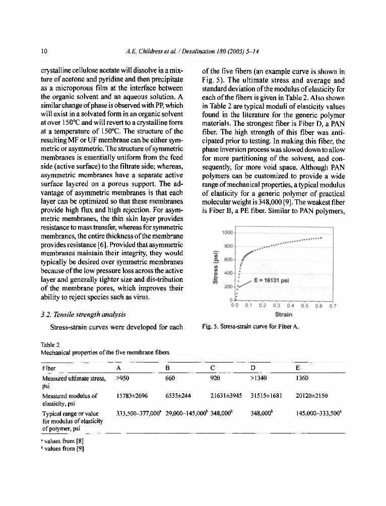
Stress-strain curves were developed for each
of the five fibers (an example curve is shown in Fig. 5). The ultimate stress and average and standard deviation of the modulus of elasticity for each of the fibers is given in Table 2. Also shown in Table 2 are typical moduli of elasticity values found in the literature for the generic polymer materials. The strongest fiber is Fiber D, a PAN fiber. The high strength of this fiber was anti- cipated prior to testing. In making this fiber, the phase inversion process was slowed down to allow for more partitioning of the solvent, and con- sequently, for more void space. Although PAN polymers can be customized to provide a wide range of mechanical properties, a typical modulus of elasticity for a generic polymer of practical molecular weight is 348,000 [9]. The weakest fiber is Fiber B, a PE fiber. Similar to PAN polymers,
A
1000 .........................................................................................
800 ............................ ~ ..............................................
ooo r i l l .......................................... t
400., ~ .........................................................................
~/ E = 16131 psi 200 . . . . . . . . . . . . . . . . . . . . . . . . . . . . . . . . . . . . . . . . . . . . .
0.0 0.1 0.2 0.3 0.4 0,5 0,6 0.7
Strain
Fig. 5. Stress-strain curve for Fiber A.
Table 2 Mechanical properties of the five membrane fibers
Fiber A B C D E
Measured ultimate stress, >950 660 920 >1340 psi Measured modulus of 15783+2696 6535+244 21631±3945 31515+1681 elasticity, psi Typical range or value 333,500-377,000 a 29,000-145,000 b 348,000 b 348,000 b for modulus of elasticity of polymer, psi
1360
20120-J:2150
145,000-333,500 a
a values from [8] b values from [9]
,4.E. Childress et al. / Desalination 180 (2005) 5-14 11
the properties of PE polymers can vary widely with molecular weight, molecular weight distri- bution, degree of branching, type and placement of branching and end group moieties [8]. Atypical range for moduli of elasticity for PE is 29,000- 145,000 psi [9]. Fibers A (PS), C (PAN), and E (PVDF) have intermediate strengths ranging from 15,783 to 21,631 psi. The modulus of elasticity of PS is typically between 333,500 and 377,000 psi [8]. The modulus of elasticity of PVDF is typically between 145,000 and 333,500 psi [8].
Although the moduli of elasticity measured in this investigation follow the general trend found in the literature with PAN being strong and PE being weak, they were typically an order of magnitude less than the literature values. This is likely because the values in the literature are general characteristics of the polymers and not specifically for hollow fiber geometries.
Modulus of elasticity is a crucial parameter for the calculation of the collapse pressure (P) of a given fiber. As a thick-walled cylinder, a hollow fiber is required to withstand high transmembrane pressure without collapsing. Pc is linearly depen- dent on the modulus of elasticity. With a much more porous overall structure, asymmetric hollow fibers specifically require a high modulus of elas- ticity to avoid collapse of the filament. For high pressure-driven processes like reverse osmosis, it is recommended to keep the internal diameter of the fibers at the order of magnitude of the fiber wall thickness. However, for MF and UF systems, where the transmembrane pressure is much less, the internal diameter can be significantly larger than the fiber wall. This allows for inside-out filtration (without the risk of lumen clogging), and generally reduces the hydraulic resistance offered by the membrane [10].
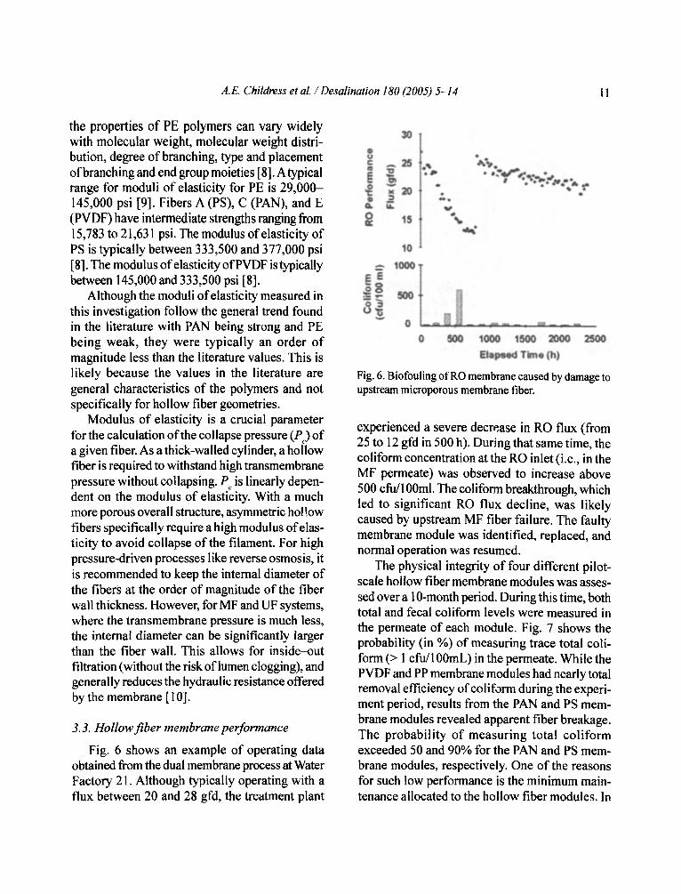
3.3. Hollow fiber membrane performance
Fig. 6 shows an example of operating data obtained from the dual membrane process at Water Factory 21. Although typically operating with a flux between 20 and 28 gfd, the treatment plant
30
is "%
l o
~000 I
0 500 1000 I~00 2000
Fig. 6. Biofouling of RO membrane caused by damage to upstream microporous membrane fiber.
experienced a severe decrease in RO flux (from 25 to 12 gfd in 500 h). During that same time, the coliform concentration at the RO inlet (i.e., in the MF permeate) was observed to increase above 500 cfu/100ml. The coliform breakthrough, which led to significant RO flux decline, was likely caused by upstream MF fiber failure. The faulty membrane module was identified, replaced, and normal operation was resumed.
The physical integrity of four different pilot- scale hollow fiber membrane modules was asses- sed over a 10-month period. During this time, both total and fecal coliform levels were measured in the permeate of each module. Fig. 7 shows the probability (in %) of measuring trace total coli- form (> 1 cfu/100mL) in the permeate. While the PVDF and PP membrane modules had nearly total removal efficiency of coliform during the experi- ment period, results from the PAN and PS mem- brane modules revealed apparent fiber breakage. The probability of measuring total coliform exceeded 50 and 90% for the PAN and PS mem- brane modules, respectively. One of the reasons for such low performance is the minimum main- tenance allocated to the hollow fiber modules. In

12 A.E. Childress et al. / Desalination 180 (2005) 5-14
J i
soi" .=o
! , i ....................................................................................................
PVDF (n=43} PP (n--~22) PAN (n=I6) PS (n=20) MF / Symmetric UF f Asymmetric
Fig. 7. Probability (in %) of measuring trace coliform (>l cfu/100 mL) in the permeate. The number of samples taken within the experimental period is given by n.
[:;Tot='~I Colfforrns : i . . . . . . . . . . . . . . . . . . . . . . . . . . . . . . . . . . . !
@ Fecal Coliform I I i . . . . . . . !
.......................
other words, when failure was observed, no attempt to repair the faulty membrane was undertaken. However, it can be concluded from these series of tests that both symmetric and MF membranes seems less prone to failure than those with an asymmetric structure and a lower nominal pore size (i.e., UF membranes).
3. 4. Dynamic modeling
Fig. 8 shows top and side perspectives of a dynamically potted membrane with an elastomer overlay (similar to Fibers C and D). Five fibers are included in the unit. The boundary conditions allow translational movement in they and z di~'ec- tions, but no translational movement in the axial (x) direction. Rotational degrees of freedom have been fixed in all directions. The fluid structure interface boundary includes the outer and inner faces of the fibers and the top of the elastomer. Pressure loading occurs on the outer fiber faces and the top surface of the elastomer.
Fig. 9 is the fluid model counterpart of the structural model just described. A block of fluid is shown on top of the elastomer boundary and surrounding the outside of the fibers. There is a no-slip boundary condition on the outside walls
Top view
I
Side view
Fig. 8. Structural model of a dynamically potted module with elastomer overlay.
Side view
[~-X Z X
Fig, 9. Fluid model of a dynamically potted module with elastomer overlay.

A.E. Childress et aL / Desalination 180 (2005) 5-14 13
of the fluid block, corresponding to the no-slip conditions on the outer walls of the entire unit. The fluid-structure interface boundary corresponds to those mentioned before, including the inner and outer faces of the fibers and the top of the elastomer. A prescribed fluid velocity is applied to the top surface of the fluid block.
An example of preliminary modeling results for the ADINA-F model is shown in Fig. 10. This figure illustrates the y-displacement of water by showing the block of fluid outside of the fibers and the fluid flowing down the inside of the fibers. The white areas observed around the fiber/poRing junction indicate significant displacement. Darker regions located within the white areas reveal even greater displacement of the fiber. As water hits the surface of the elastomer, it is being displaced near the fiber-elastomer juncture. This indicates that there are additional stresses at the juncture that may lead to the formation of fractures.
Results from this dynamic modeling reveal the importance of the choice of poring material and technique. Not only should the poring material be effective and non-toxic, it should also be com- patible with the fiber material. Epoxy resins, poly- urethanes, and silicone rubbers are three of the most commonly used potting materials that have surface tensions which allow proper weRing of the hollow fibers. A good potting agent must not penetrate the fiber, plug the bore, damage the
¥-D~SPLACE~ENT TIHE t.000
~ 0,05400 _ 0.036~
&01800 ozeooo
~- ~0.01800 i b ~o~oz4oo ~7 -0.05400
Fig. 10. ADINA simulation showing they-displacement of water for a dynamically potted module with elastomer overlay.
ultrathin coating, or creep under pressure [10]. And ideally, the potting agent would not wick up the fiber walls.
4. Conclusions and recommendations
Numerous factors must be considered when selecting the most appropriate microporous mem- brane and module for a given application. These include membrane material, membrane symmetry, fiber modulus of elasticity, fiber diameter and thickness, module potting technique, and module flow pattern (inside-out or outside-in). Although asymmetric membranes generally provide similar rejection with lower intrinsic hydraulic resistance than symmetric membranes, results obtained during this study show that the asymmetric mem- branes have a higher propensity of failure. Optimi- zation of the compatibility between the hollow fiber membranes and poring material and tech- nique should be further studied since this study revealed the presence of substantial stresses at the fiber/poRing interface.
This paper was an attempt to reconcile direct field observations with some mechanical proper- ties of the fiber/module system. The results should be interpreted cautiously, as the tensile moduli of the samples were determined by performing short- term mechanical testing under simple loading con- ditions. A more complete assessment of the mechanical performance of these polymer fibers should consider longer-term mechanical proper- ties such as creep and fatigue. Additionally, temp- erature and environmental factors should be taken into consideration.
Information acquired from the study of micro- porous membrane fiber integrity will assist with the development and manufacture of longer lasting MF and UF membranes and modules for the reclamation market. Additionally, it has been shown [11 ] that the presence of broken fibers results in deterioration of backwash efficiency because broken fibers will hydraulically consume a larger proportion of flow due to their reduced resistance. Reductions in operation and maintenance costs
14 A.E. Childress et al. / Desalination 180 (2005) 5-14
associated with loss of membrane fiber integrity will allow this technology to be more competitive with less effective existing technologies.
Acknowledgments
Funding for this project was provided by the California Energy Commission's Public Interest Energy Research Program. The authors wish to express appreciation for the project management by Lory L. Larson, Southern California Edison. Support was also provided by Shivaji Deshmukh and Mehul Patel of Orange County Water District, Fountain Valley, California. The authors are also grateful to John McCormack o f the University of Nevada, Reno, Electron Microbeam Facility for conducting the SEM analyses.
References
[1 ] A. Brehant, V. Bonnelye and M. Perez, Comparison ofMF/UF pretreatment with conventional filtration prior to RO membranes for surface seawater filtration, Desalination, 144 (2002) 353-360.
[2] C.J. Gabelich, T.I. Yun, B.M. Coffey and I.H. Suffet, Pilot-scale testing of reverse osmosis using conven- tional treatment and microfiitration, Desalination, 154 (2003) 207-223.
[3] S.B.S. Ghayeni, EJ. Beatson, R.P. Schneider and A.G. Fane, Water reclamation from municipal waste- water using combined microfiltration-reverse osmosis (MF-RO): preliminary performance data and microbiological aspects of system operation, Desalination, 116 (1998) 65-80.
[4] B. Durham and A. Walton, Membrane pretreatment of reverse osmosis: long-term experience on difficult waters, Desalination,122 (1999) 157-170.
[5] J. Schaefer, Reliable water supply by reusing waste- water after membrane treatment, Desalination, i 38 (2001)91-101.
[6] M.H.V. Mulder, Basic Principles of Membrane Tech- nology, Kluwer Academic Publishers, Dordrecht, The Netherlands, 2001.
[7] 1.H. Huisman and K. Williams, Autopsy and failure analysis of ultrafiltration membranes from a waste- water treatment system, Desalination, 165 (2004) 161-164.
[8] H.F. Mark, Encyclopedia of Polymer Science and Technology, John Wiley and Sons, Inc., Hoboken, N.J., 2003.
[9] P.J. Corish, Concise Encyclopedia of Polymer Pro- cessing and Applications, 1992.
[10] I. Moch, Hollow-fiber membranes, in: J.l. Kroschwitz, Ed., Kirk-Othmer Encyclopedia of Chemical Technology, Wiley lnterscience, Hoboken, N.J., 1995.
[11] P. Hillis, M.B. Padley, N.I. Poweil and P.M. Gal- lagher, Effects of backwash conditions on out-to- in membrane microfiltration, Desalination, 118 (1998) 197-204.