MECA0492 : Vehicle dynamics - ULiege · MECA0492 : Vehicle dynamics Pierre Duysinx Research Center...
74
MECA0492 : Vehicle dynamics Pierre Duysinx Research Center in Sustainable Automotive Technologies of University of Liege Academic Year 2017-2018 1
Transcript of MECA0492 : Vehicle dynamics - ULiege · MECA0492 : Vehicle dynamics Pierre Duysinx Research Center...

MECA0492 : Vehicle dynamics
Pierre DuysinxResearch Center in Sustainable Automotive
Technologies of University of Liege
Academic Year 2017-2018
1

MECA0492 Vehicle Dynamics
Monday 13/11 AM & PM (@Campus)
Tyre Mechanics P. Duysinx
Vehicle dynamics, influence P. Sachettini (JTEKT)
of the differential(s) and 4W
Tuesday 14/11 AM&PM (@Campus)
Intro to measurements Ph. Kever (Campus)
Vehicle balancing (settings) Ph. Kever (Campus)
Wednesday 15/11 AM &PM (@ULG)
Steady State Cornering P. Duysinx
Effect of roll behaviour on SSC P. Duysinx
2
MECA0492 Vehicle Dynamics
Thursday 16/11 AM & PM (@Campus)
Vehicle Aerodynamics R. Hilhorst (TMG)
Monday 27/11 PM
Vehicle suspension technologies P. Duysinx
Monday 04/12 PM
Vehicle stability P. Duysinx
Thursday 07/12 AM (9h30, Ford Lommel)
Visit Ford Lommel Proving ground O. Duysens (Ford)
3

MECA0492 Vehicle Dynamics
Monday 11/12 AAM (@ULG)
Active Vehicle Stability Control (ESP) P. Duysinx
4
Bibliography
T. Gillespie. « Fundamentals of vehicle Dynamics », 1992, Society of Automotive Engineers (SAE)
W. Milliken & D. Milliken. « Race Car Vehicle Dynamics », 1995, Society of Automotive Engineers (SAE)
R. Bosch. « Automotive Handbook ». 5th edition. 2002. Society of Automotive Engineers (SAE)
J.Y. Wong. « Theory of Ground Vehicles ». John Wiley & sons. 1993 (2nd edition) 2001 (3rd edition).
M. Blundel & D. Harty. « The multibody Systems Approach to Vehicle Dynamics » 2004. Society of Automotive Engineers (SAE)
G. Genta. «Motor vehicle dynamics: Modelling and Simulation ». Series on Advances in Mathematics for Applied Sciences - Vol. 43. World Scientific. 1997.
5

INTRODUCTION TO HANDLING
6

Introduction to vehicle dynamics
Introduction to vehicle handling
Vehicle axes system
Tire mechanics & cornering properties of tires
Terminology and axis system
Lateral forces and sideslip angles
Aligning moment
Single track model
Low speed cornering
Ackerman theory
Ackerman-Jeantaud theory
7

Introduction to vehicle dynamics
High speed steady state cornering
Equilibrium equations of the vehicle
Gratzmüller equality
Compatibility equations
Steering angle as a function of the speed
Neutral, understeer and oversteer behaviour
Critical and characteristic speeds
Lateral acceleration gain and yaw speed gain
Drift angle of the vehicle
Static margin
Exercise
8

Introduction
In the past, but still nowadays, the understeer and oversteercharacter dominated the stability and controllability considerations
This is an important factor, but it is not the sole one…
In practice, one has to consider the whole system vehicle + driver
Driver = intelligence
Vehicle = plant system creating the manoeuvering forces
The behaviour of the closed-loop system is referred as the « handling », which can be roughly understood as the road holding
9

Introduction
Model of the system vehicle + driver
10

Introduction
However because of the difficulty to characterize the driver, it is usual to study the vehicle alone as an open loop system.
Open loop refers to the vehicle responses with respect to specific steering inputs. It is more precisely defined as the ‘directional response’ behaviour.
The most commonly used measure of open-loop response is the understeer gradient
The understeer gradient is a performance measure under steady-state conditions although it is also used to infer performance properties under non steady state conditions
11

AXES SYSTEM
12

Reference frames
Local reference frame oxyz attached to the vehicle body -SAE (Gillespie, fig. 1.4)
XY Z
O
Inertial coordinate system OXYZ
13

Reference frames
Inertial reference frame
X direction of initial displacement or reference direction
Y right side travel
Z towards downward vertical direction
Vehicle reference frame (SAE):
x along motion direction and vehicle symmetry plane
z pointing towards the center of the earth
y in the lateral direction on the right hand side of the driver towards the downward vertical direction
o, origin at the center of mass
14

Reference frames
z
x
y x
Système SAE
Système ISO
x z
yComparison of conventions of SAE and ISO/DIN reference frames
15

Local velocity vectors
Vehicle motion is often studied in car-body local systems
u : forward speed (+ if in front)
v : side speed (+ to the right)
w : vertical speed (+ downward)
p : rotation speed about a axis (roll speed)
q : rotation speed about y (pitch)
r : rotation speed about z (yaw)
16

Forces
Forces and moments are accounted positively when acting ontothe vehicle and in the positive direction with respect to the considered frame
Corollary
A positive Fx force propels the vehicle forward
The reaction force Rz of the ground onto the wheels is accounted negatively.
Because of the inconveniency of this definition, the SAEJ670e « Vehicle Dynamics Terminology » names as normal force a force acting downward while vertical forces are referring to upward forces
17

TIRE MECHANICS: CORNERING PROPERTIES
18

Terminology and axis system (SAE)
Wheel plane: central plane of the tire normal to the axis of rotation
Wheel centre: intersection of the spin axis with the wheel plane
Centre of Tire Contact: intersection of the wheel plane and the projection of the spin axis onto the road plane
Loaded radius: distance from the centre of tire contact to the wheel centre in the wheel plane
19

Terminology and axis system (SAE)
Longitudinal Force Fx :component of the force acting on the tire by the road in the plane of the road and parallel to the intersection of the wheel plane with the road
Lateral Force Fy : component of the force acting on the tire by the road in the plane of the road and normal to the intersection of the wheel plane with the road plane
Normal Force Fz : component of the force acting on the tire by the road which is normal to the plane of the road
20

Terminology and axis system (SAE)
Overturning Moment Mx : moment acting on the tire by the road in the plane of the road and parallel to the intersection of the wheel plane with the road plane
Rolling Resistance Moment My :moment acting on the tire by the road in the plane of the road and tending to rotate the wheel about the y axis
Aligning Moment Mz : moment acting on the tire by the road which is normal to the road plane
21

Terminology and axis system (SAE)
Slip Angle (a): angle between the direction of the wheel heading and the direction of travel.
A positive sideslip corresponds to a tire moving to the right while rolling in the forward direction
Camber Angle (g): angle between the wheel plane and the vertical direction.
A positive camber corresponds to the top of the tire leaned outward from the vehicle
22
LATERAL FORCES
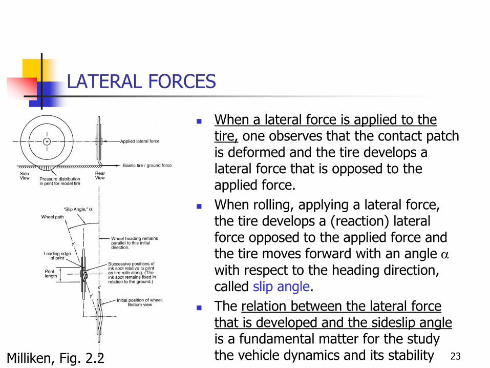
When a lateral force is applied to the tire, one observes that the contact patch is deformed and the tire develops a lateral force that is opposed to the applied force.
When rolling, applying a lateral force, the tire develops a (reaction) lateral force opposed to the applied force and the tire moves forward with an angle awith respect to the heading direction, called slip angle.
The relation between the lateral force that is developed and the sideslip angle is a fundamental matter for the study the vehicle dynamics and its stabilityMilliken, Fig. 2.2 23

ORIGIN OF LATERAL FORCES
The origin of the tire deformation is the applied lateral force
Gillespie, Fig 10.10Wong Fig 1.22
24

LATERAL FORCES
The name of sideslip is misleading since there is no global slip of the tire with respect to the ground (except in a very limited part at the back of the contact patch).
The sideslip of the tire is due to the flexible character of the rubber tire that allows keeping a heading while having a lateral motion
The lateral force may be a cause or a consequence of the sideslip.
Lateral forces (gust) sideslip reaction forces
under the tire
Steering the wheel sideslip lateral forces to
turn
Analogy with walking a snow slope
25
LATERAL FORCES
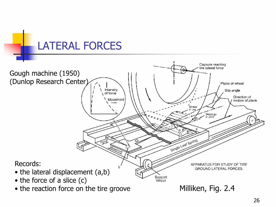
Gough machine (1950)(Dunlop Research Center)
Milliken, Fig. 2.4
Records:• the lateral displacement (a,b)• the force of a slice (c)• the reaction force on the tire groove
26

LATERAL FORCES
Side displacements
Lateral speedA>B : V sina
B>C: local slip
Genta Fig 2.24
Distribution of contact pressure sz: centre of
pressure is in the front part of the contact patch rolling
resistance
Distribution of tzy = lateral shear of the tire: Triangular distribution.Its resultant force is
located in the back of the contact patch
aligning moment
27

LATERAL FORCES
From experimental observations, one notices that: The resultant of the lateral force is located in the rear part of the
pneumatic contact patch.
The distance between the resultant force position and the centre of the contact pact is the pneumatic trail t
The lateral forces produces also an aligning moment
The local slippage of the tire on the road is limited to a small zone at the back of the contact patch. Its span depends on the sideslip angle.
The characteristics of the lateral forces are related, in the small sideslip angles, to the lateral displacements due to the rolling process but they are mostly independent of the speed.
z yM F t
28

LATERAL FORCES
Genta Fig 2.23 : Contact zone in presence of sideslipa/ Contact zone and trajectory of a point in the treadb/ Contact zones et slippage zone for different sideslip angles
29

LATERAL FORCES
3 parts in the curves of Fy as a function of the sideslip angle
Linear part for small sideslip angles (< 3°)
In the frictional part (>7°) most of the contact patch experiences dry friction. Beyong the peak of the curves, the lateral force can fall rapidly or remain smooth
Transition part: end of linear regime (~3°) to the peak value of the curve (~7°)
On wet roads, the peak value is reduced and drops rapidly
P215/60 R15 GoodYear Eagle GT-S(shaved for racing) 31 psiVertical load 1800 lb
Milliken. Fig. 2.730

LATERAL FORCES
P215/60 R15 Goodyear Eagle GT-S (saved for racing) 31 psi
Milliken. Fig. 2.8 et Fig. 2.9
µ=Fy/Fz
31

LATERAL FORCES
One introduces the friction coefficient as the ratio of the lateral force and of the applied vertical load
µ = Fy/ Fz
The peak value of the lateral force is reduced with the vertical load: this is the load sensitivity phenomenon.
The modification of the lateral force with the vertical load can be important with old bias tires. This affects the total lateral force capability of the wheel sets when experiencing lateral load transfer.
Milliken. Fig. 2.10 32
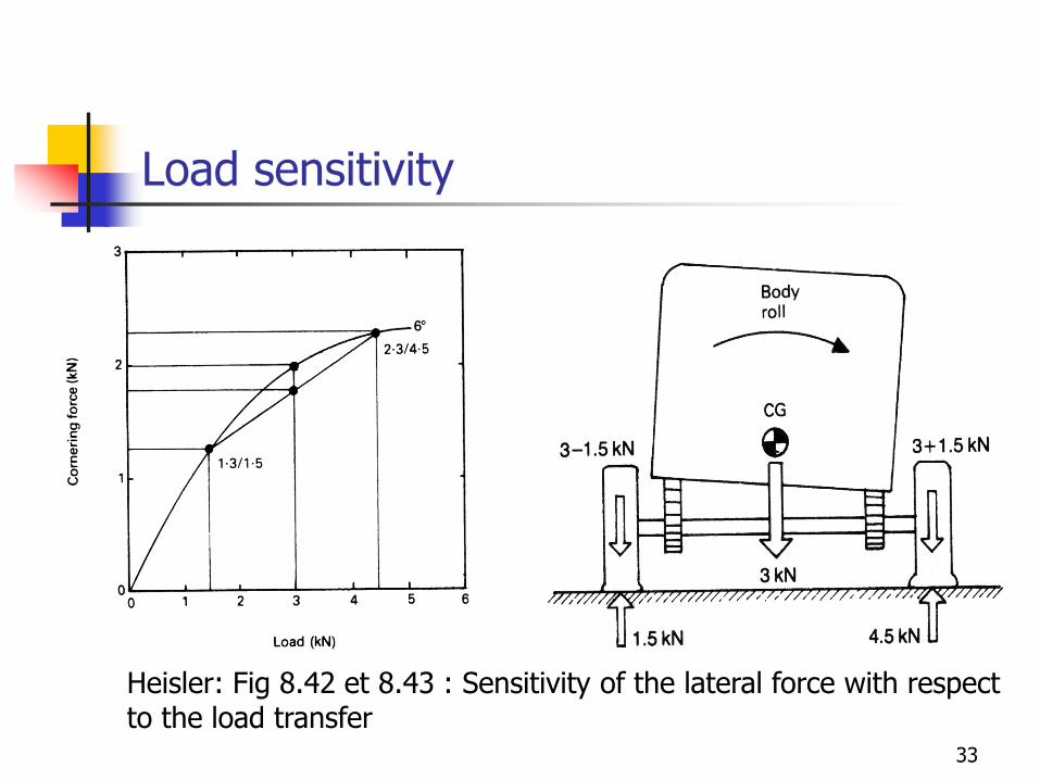
Load sensitivity
Heisler: Fig 8.42 et 8.43 : Sensitivity of the lateral force with respect to the load transfer
33

Cornering stiffness
In its linear part (small sideslip angles) the lateral force curve can be approximated by its Taylor first order expansion :
Fy = -Ca a
Ca is called as the cornering stiffness.
The cornering stiffness is negative
Gillespie Fig. 6.234
Cornering stiffness
The cornering stiffness depends on several parameters:
The type of the tire, its sizes and width,
The inflating pressure
The vertical load
The order of magnitude of the cornering stiffness is about 50000 N/rad
As the lateral force is quite sensitive to the vertical load, one generally prefers to use the cornering coefficient that is defined as the ratio of the cornering stiffness by the vertical load:
CCa Ca / Fz
The order of magnitude of CCa is in the range 0.1 to 0.2 N/N degre-1
35
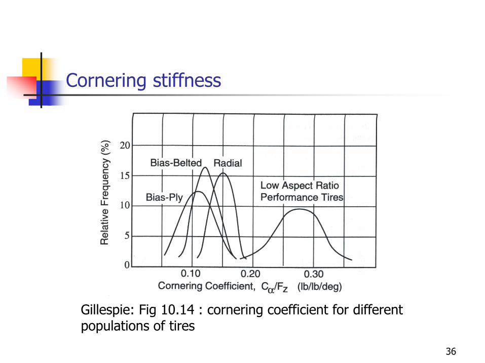
Cornering stiffness
Gillespie: Fig 10.14 : cornering coefficient for different populations of tires
36
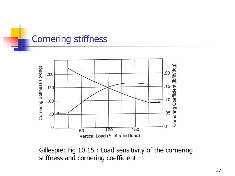
Cornering stiffness
Gillespie: Fig 10.15 : Load sensitivity of the cornering stiffness and cornering coefficient
37
ALIGNING MOMENT AND PNEUMATIC TRAIL
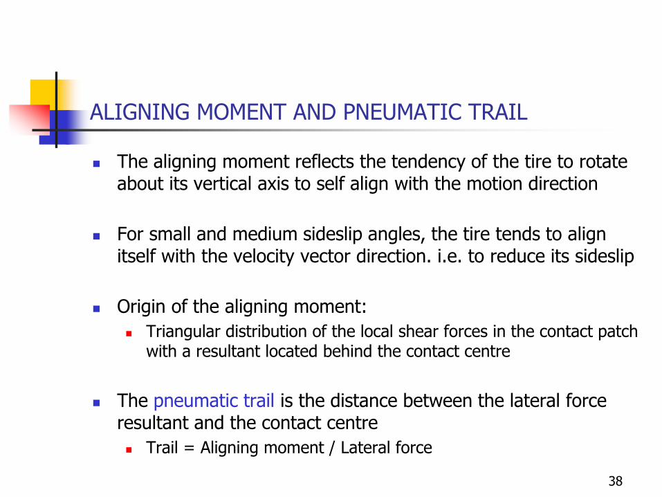
The aligning moment reflects the tendency of the tire to rotate about its vertical axis to self align with the motion direction
For small and medium sideslip angles, the tire tends to align itself with the velocity vector direction. i.e. to reduce its sideslip
Origin of the aligning moment:
Triangular distribution of the local shear forces in the contact patch with a resultant located behind the contact centre
The pneumatic trail is the distance between the lateral force resultant and the contact centre
Trail = Aligning moment / Lateral force
38

Aligning moment and pneumatic trail
Linear part - small sideslip angles (<3°): The largest shear stresses
work to reduce the sideslip
Non-linear part – medium and large sideslip angles Maximum of the curves
about 3 to 4° When the rear of the
contact patch is invaded with local friction, the aligning moment is reducing
At the maximum of the lateral force, the aligning moment goes to zero and may even become negative for larger sideslip angles a > 7° à 10°
Milliken. Fig. 2.11 39

Aligning moment and pneumatic trail
The aligning moment can also be reinforced with a mechanical trail coming from the wheel and the steering geometry
Optimum combination of both trails : Too small mechanical trail,
the vehicle can loose its aligning torque capability with the saturation of lateral force
Too large mechanical trail, no feeling of the maximum of the lateral force curve
Milliken. Fig. 2.12
40

Aligning moment and pneumatic trail
Lateral force and aligning moment for a tire 175/70 R 13 82SFrom Reimpell et al.
41
Aligning moment and pneumatic trail
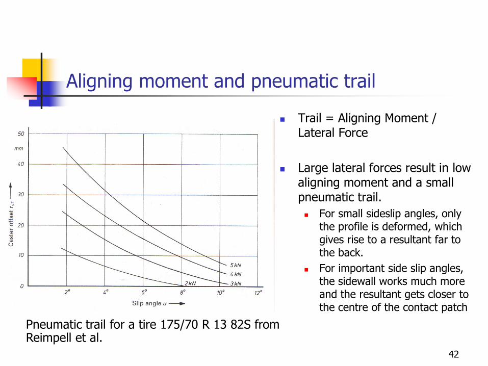
Trail = Aligning Moment / Lateral Force
Large lateral forces result in low aligning moment and a small pneumatic trail.
For small sideslip angles, only the profile is deformed, which gives rise to a resultant far to the back.
For important side slip angles, the sidewall works much more and the resultant gets closer to the centre of the contact patch
Pneumatic trail for a tire 175/70 R 13 82S from Reimpell et al.
42

EFFECT OF CAMBER
Definition of camberWong Fig.1.40
43

Camber change
The inclination of the wheel outward from the body is called the camber angle.
Camber on a wheel will produce a lateral force known as camber thrust.
The camber thrust is oriented toward to the intersection of the wheel rotation axis with the ground

Camber thrust
Origin of the camber thrust:
The contact patch is deformed and takes a banana shape
The tyre particles would like to follow a circular trajectory which creates a double shear stress distribution.
The net resultant of the shear stress distribution is oriented towards the centre of rotation of the cambered wheel
Distorted contact patch because of camberMilliken : Fig 2.23
45

Camber thrust
The camber thrust is oriented towards the centre of rotation of the cambered wheel
The tyre develops a lateral force even if there is no slip angle.
Camber thrust and cornering forces due to slip are additive phenomena at least for small values
The magnitude of the camber thrust depends on
The camber angle
The type of tyre, its constructive characteristics
The shape of the tread
The inflating pressure (strongly)
The braking / tractive forces
The slip angle
The camber thrust is little sensitive to load and speed

Camber thrust
In its linear part, (small camber angles), the camber thrust angle can be approximated by the linear relation:
Fy = Cg g
Cg is the camber stiffness
Gillespie Fig. 6.1447

Camber thrust
The camber thrust produces much smaller lateral forces than an equivalent slip angle. About 4 to 6 degrees of camber produce the same lateral force as
1 degree of side slip for a bias tyre.
For radial tyres, as much as 10 to 15 degrees are necessary for 1 degree of slip
This can be understood because the side slip produces a much bigger deformation of the tyre tread. For radial tyre, the sidewall are even softer and the belts are very rigid.
For passenger car, the camber thrust is fading out for camber thrust over 5 to 10 degrees
For motorbikes tyres with round profiles and bias structures, the camber thrust can be generated up to 50 degrees
48
Camber thrust
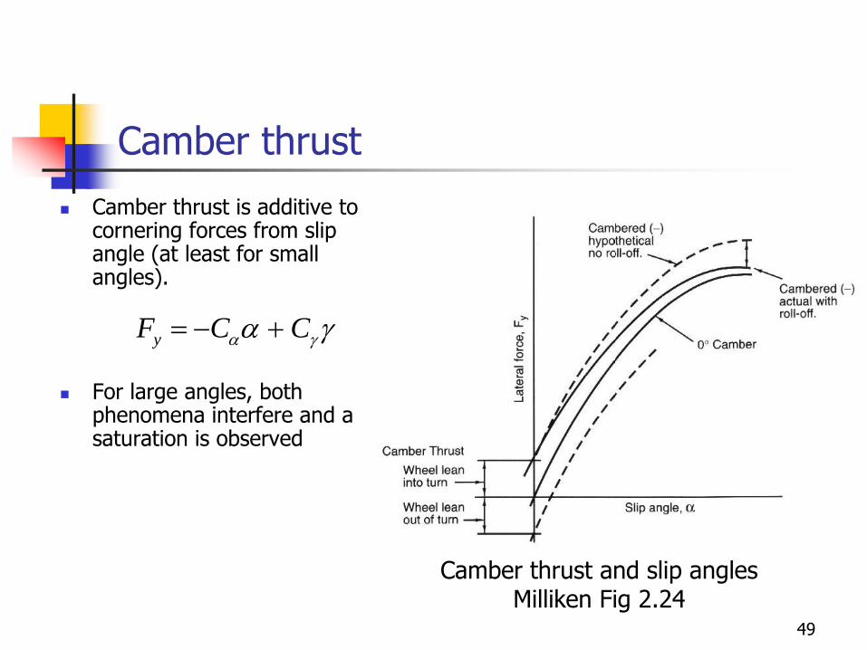
Camber thrust is additive to cornering forces from slip angle (at least for small angles).
For large angles, both phenomena interfere and a saturation is observed
Camber thrust and slip anglesMilliken Fig 2.24
yF C Ca ga g
49

Camber thrust
Camber thrust for a motorbike tyre50
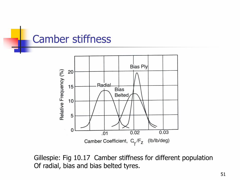
Camber stiffness
Gillespie: Fig 10.17 Camber stiffness for different populationOf radial, bias and bias belted tyres.
51
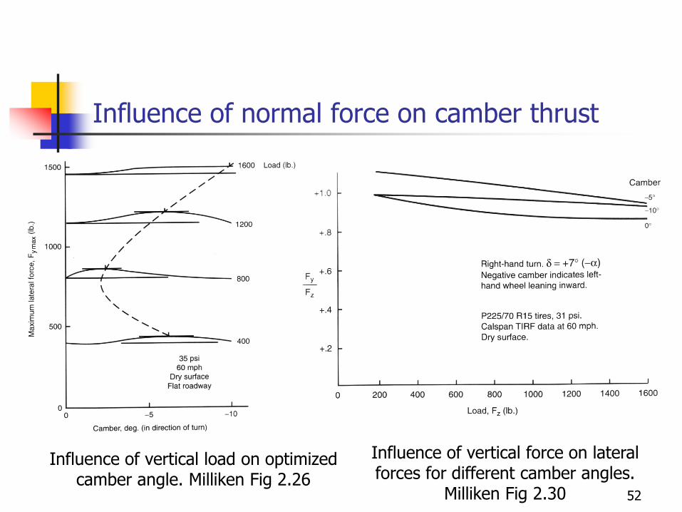
Influence of normal force on camber thrust
Influence of vertical load on optimized camber angle. Milliken Fig 2.26
Influence of vertical force on lateral forces for different camber angles.
Milliken Fig 2.30 52

Aligning torque due to camber
Generally there is no significant effect of camber thrust onto aligning moment.
Because of the symmetric pattern of the shear forces
If any, camber tends to destabilize the drift angle
It always requires a mechanical trail
53
Longitudinal forces
54

Longitudinal force generation in tires
When braking the tire rotation speed is lower than the equivalent ground velocity in the contact patch
Tread and side walls radial fibers are in shear because of the local friction between road and tire
Slip occurs only at the end of the contact patch
The resultant of the shear forces in contact patch is the longitudinal force developed by the tire
Gillespie Fig 10.6: Deformation due braking in contact patch
“Brush” model
55

Tractive force
Blundel. Fig. 5.21
56
Longitudinal force generation in tires
Longitudinal slip (Slip ratio)
SR = (W-W0)/W0 = W/W0 – 1
If Re is the effective rolling radius of the tire
SR = W Re/V – 1
Free rolling SR = 0
Wheel blocked in braking SR = -1
Spinning : SR = +1
Free slipping: SR →∞
The tractive/braking forces can be plotted in terms of the slip ratio
57

Longitudinal force generation in tires
Milliken. Fig. 2.17Milliken. Fig. 2.16
58
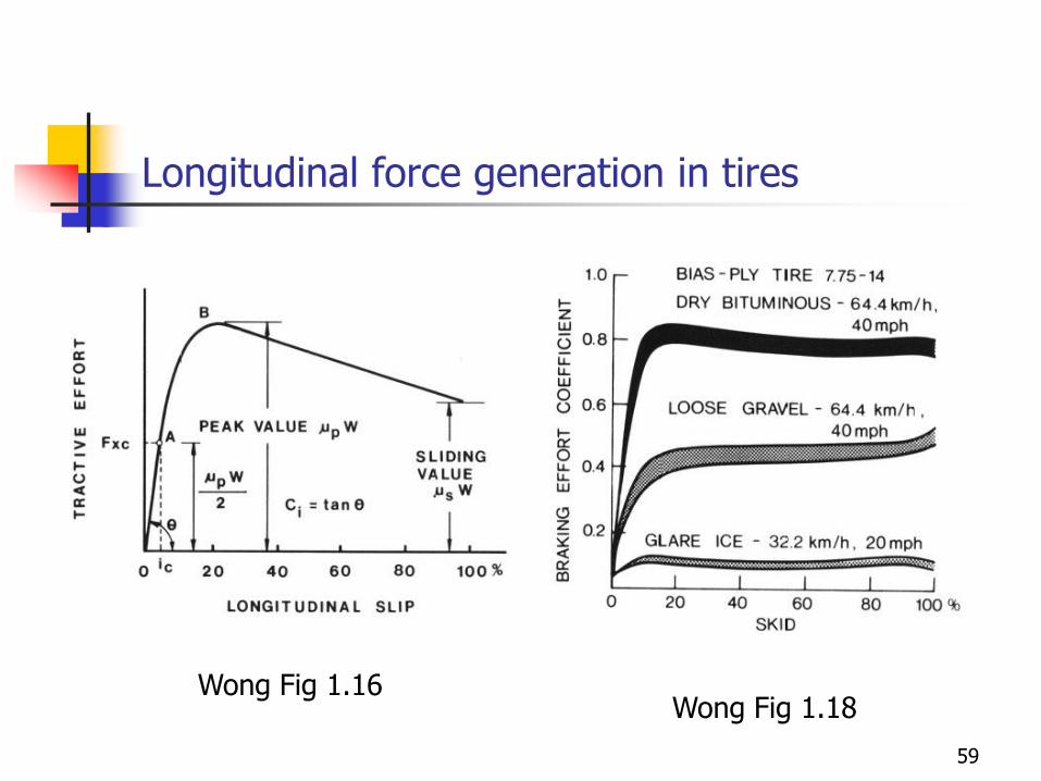
Longitudinal force generation in tires
Wong Fig 1.18Wong Fig 1.16
59
Combined operations
60

COMBINED OPERATIONS
Combined Operations results from simultaneous effects of
Longitudinal forces (braking / tractive) AND
Lateral forces (cornering)
61
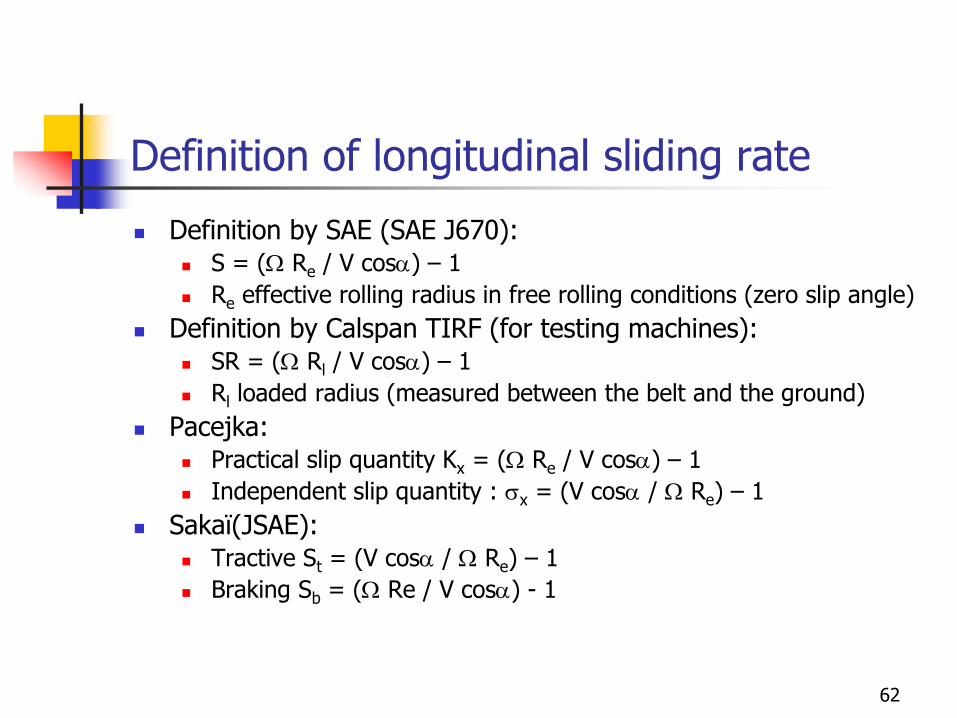
Definition of longitudinal sliding rate
Definition by SAE (SAE J670): S = (W Re / V cosa) – 1
Re effective rolling radius in free rolling conditions (zero slip angle)
Definition by Calspan TIRF (for testing machines): SR = (W Rl / V cosa) – 1
Rl loaded radius (measured between the belt and the ground)
Pacejka: Practical slip quantity Kx = (W Re / V cosa) – 1
Independent slip quantity : sx = (V cosa / W Re) – 1
Sakaï(JSAE): Tractive St = (V cosa / W Re) – 1
Braking Sb = (W Re / V cosa) - 1
62

Combined Operations
Sakaï experiment Japan Automotive Research Institute (JARI)
One of the few complete set of results to be published in public domain
Small tyres for passenger car with a moderate load of 400 kg (882 lb) and a vehicle speed of 20 km/h (12.4 mph)
Definition of longitudinal slide slip Traction St = (V cosa / W Re) – 1
Braking Sb = (W Re / V cosa) - 1
Free rolling St = Sb = 0
Wheel blocked while braking Sb = -1
Spinning wheel (acceleration) St = -½
Blocked wheel (acceleration) St = -1
63

Sakaï experiment
Braking/ Tractive forces vs sliding rate and side slip angleMilliken Fig 2.18 64

Sakaï experiment
Forces latérales vs taux de glissement et angle de dériveMilliken Fig 2.19 65

Sakaï experiment
Effect of side slip angle and longitudinal slide upon lateral force. Milliken Fig 2.20
Effect of side slip and longitudinal rate onto tractive and braking forces. Milliken Fig 2.21
66

Force magnitude v.s. effective sliding
The tyre does feel only the sliding speed and the relative longitudinal slip (i.e. the tyre is sensitive against the relative velocity between the tyre and the ground.
The tyre does feel only the relative velocity between the ground and the tyre.
Speed :
vlat = V sina
vlong = V cosa – W Re
vres = (vlat2 + vlong²)1/2
Force :
Fres = (Fx2 + Fy²)1/2
Resultant force v.s. generalized sliding rateMilliken Fig 2.22
67

Friction circle (ellipsis)
Goal : to combine in a single diagramme all relevant information given in longitudinal and lateral forces as weel as the sliding tip.
The friction circle represents the limit that a tyre can ever develop and the influence of his friends and tutors.
Motivation: the resulting force developed by the tyre as a function of the vehicle speed
68

Friction circle (ellipsis)
Braking forces and Lateral forces as a function of the sliding parameter
Gillespie Fig. 10.22
Lateral force as a function of the braking force and of the sliding rate Gillespie Fig.
10.23
69
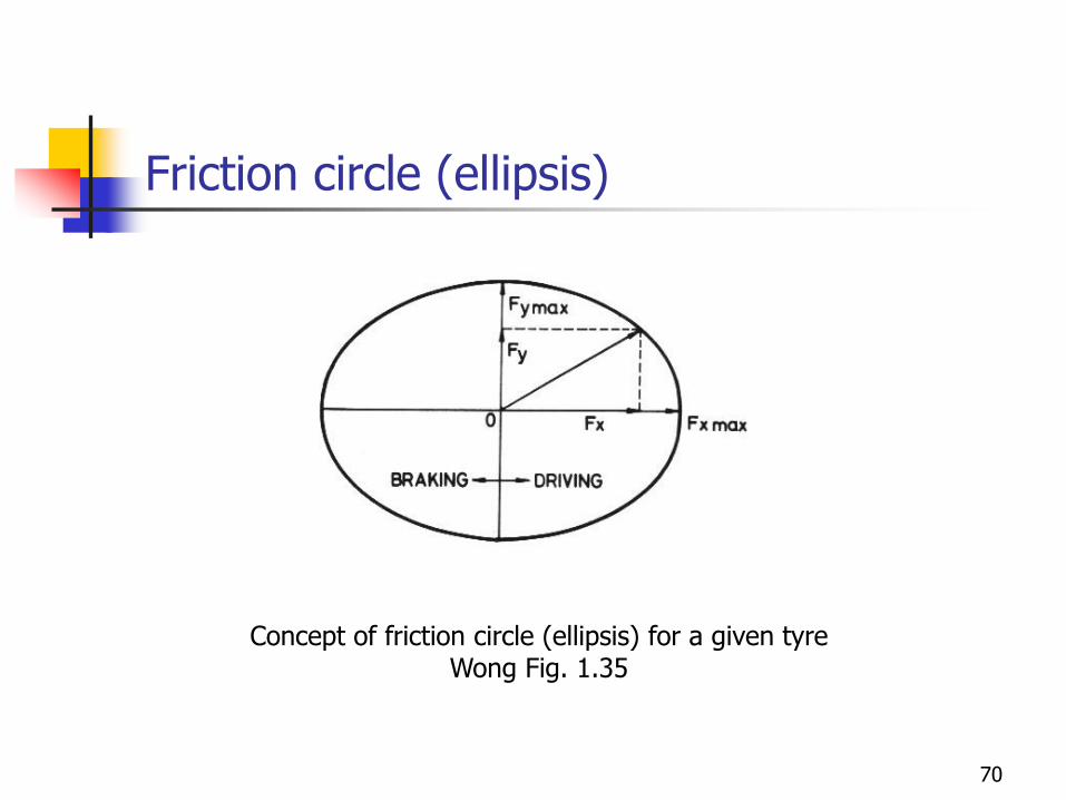
Friction circle (ellipsis)
Concept of friction circle (ellipsis) for a given tyreWong Fig. 1.35
70

Friction circle (ellipsis)
Milliken Fig 2.31Friction circle of Sakaï experiment
71

Friction circle (ellipsis)
Friction circle for a diagonal tyreWong Fig. 1.33
Friction circle for radial tyresWong Fig. 1.33
72

Cercle et ellipse de friction
Friction circle for a truck tyreWong Fig. 1.34
73

Cercle et ellipse de friction
Lateral forces and yaw moment in terms of the tractive / braking force.
Gillespie Fig. 10.2474


![A stress-based topology optimization method for ......Duysinx and Bendsøe [4] implemented relaxed local stress constraints for porous composite materials based on the SIMP method.](https://static.fdocuments.net/doc/165x107/61275f50d47229791f3c533b/a-stress-based-topology-optimization-method-for-duysinx-and-bendse-4.jpg)