Measuring RF Parameters of Networks - okdxf.eu RF Param_Final.pdfMeasuring RF Parameters of...
56
Bill Leonard NØCU NAØTC - 285 TechConnect Radio Club http://www.naØtc.org/ Measuring RF Parameters of Networks
Transcript of Measuring RF Parameters of Networks - okdxf.eu RF Param_Final.pdfMeasuring RF Parameters of...
Bill LeonardNØCU
NAØTC - 285 TechConnect Radio Clubhttp://www.naØtc.org/
Measuring RF Parameters of Networks
What is a Network?
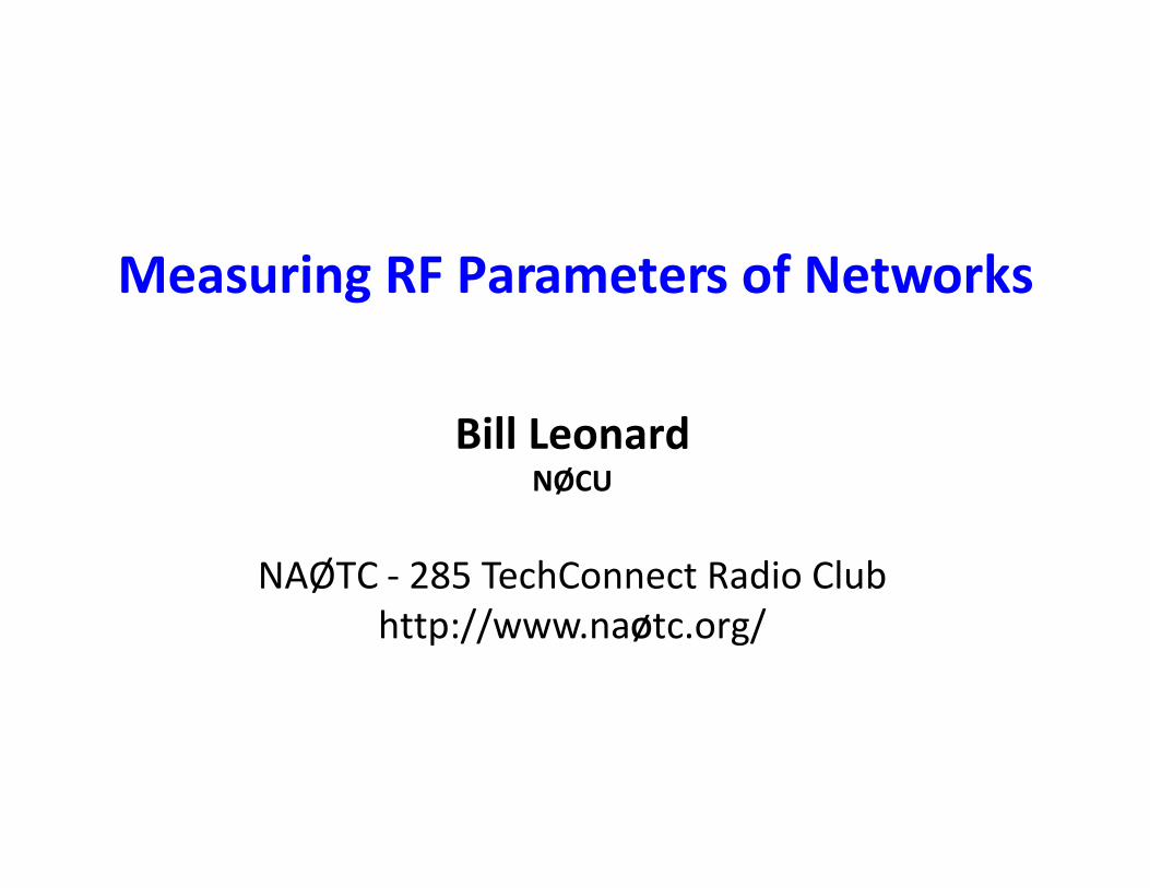
• A Network is a group of electrical components connected is a specific way in order to perform a desired electrical function– Any linear circuit with four terminals can be represented as a two-port
network with a full set of parameters– Conditions:
• A network cannot have any internal signal sources • “Port Condition” must be met: Current in = current out
2 PortNetwork
Port 1 Port 2
What is a Network?
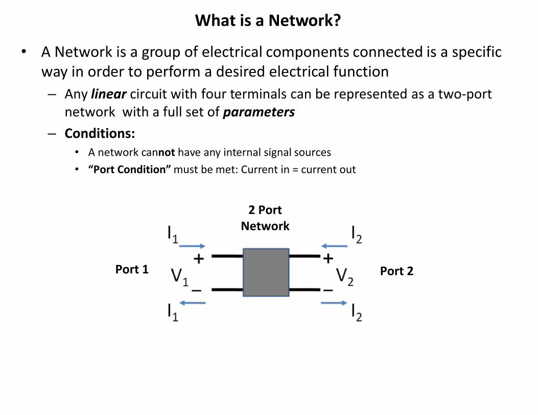
• # Port: a term that describes the number of external interfaces to the Network– A Network can have any number of ports– 1 port and 2 port networks are the most common
1 port 2 port
Dummy Load
RR
Resistive Pad
RR
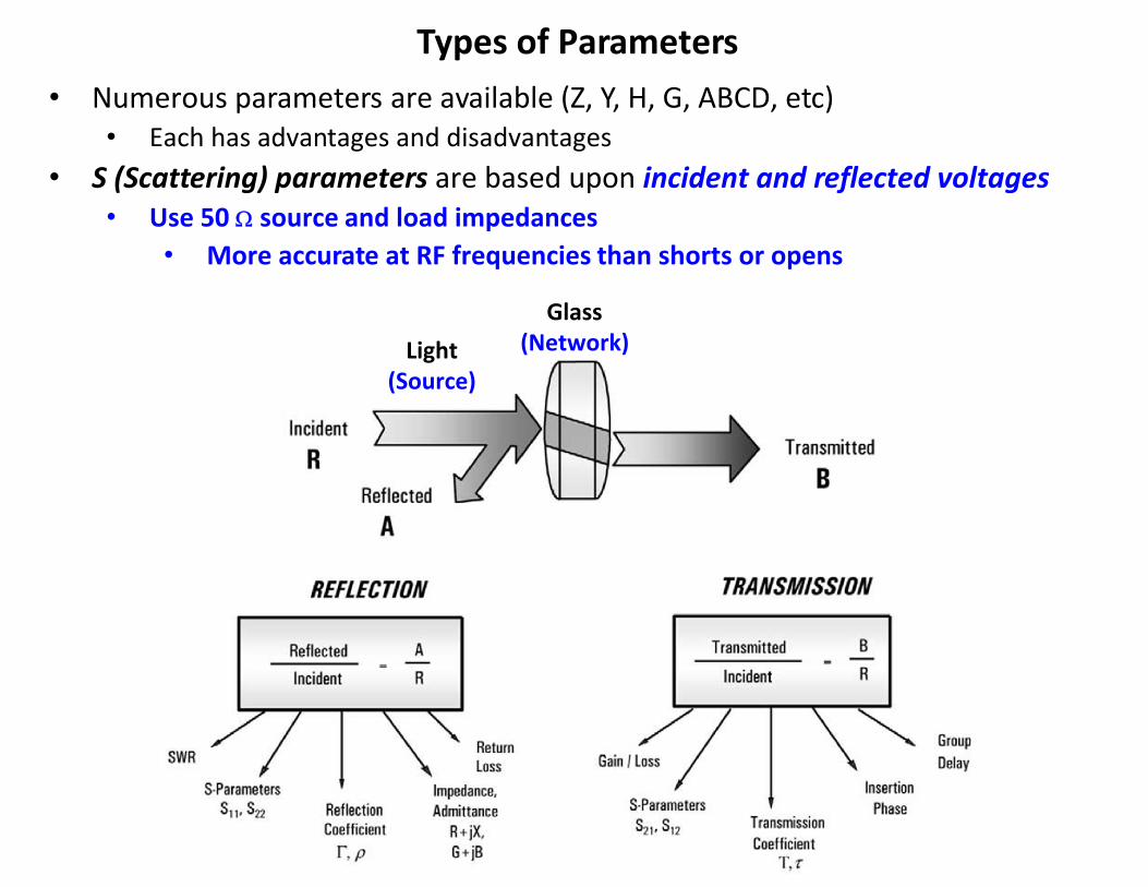
Types of Parameters• Numerous parameters are available (Z, Y, H, G, ABCD, etc)
• Each has advantages and disadvantages• S (Scattering) parameters are based upon incident and reflected voltages
• Use 50 W source and load impedances• More accurate at RF frequencies than shorts or opens
Glass(Network)Light
(Source)
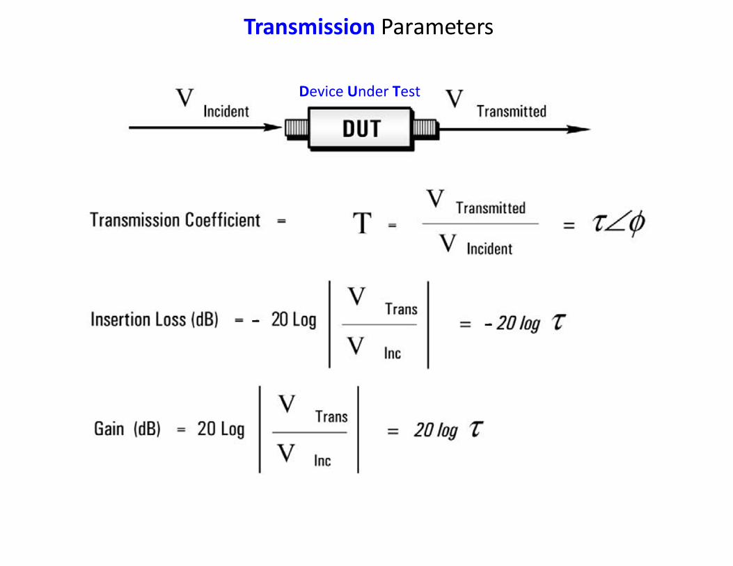
Transmission Parameters
Device Under Test
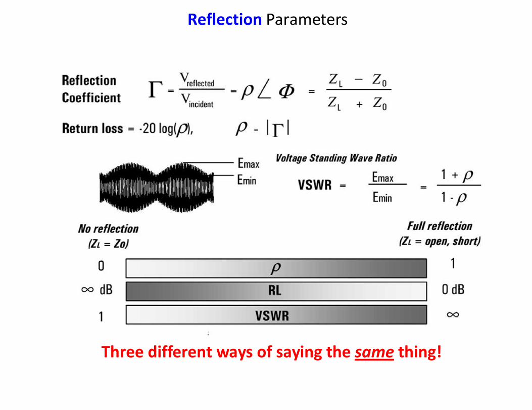
Reflection Parameters
Three different ways of saying the same thing!
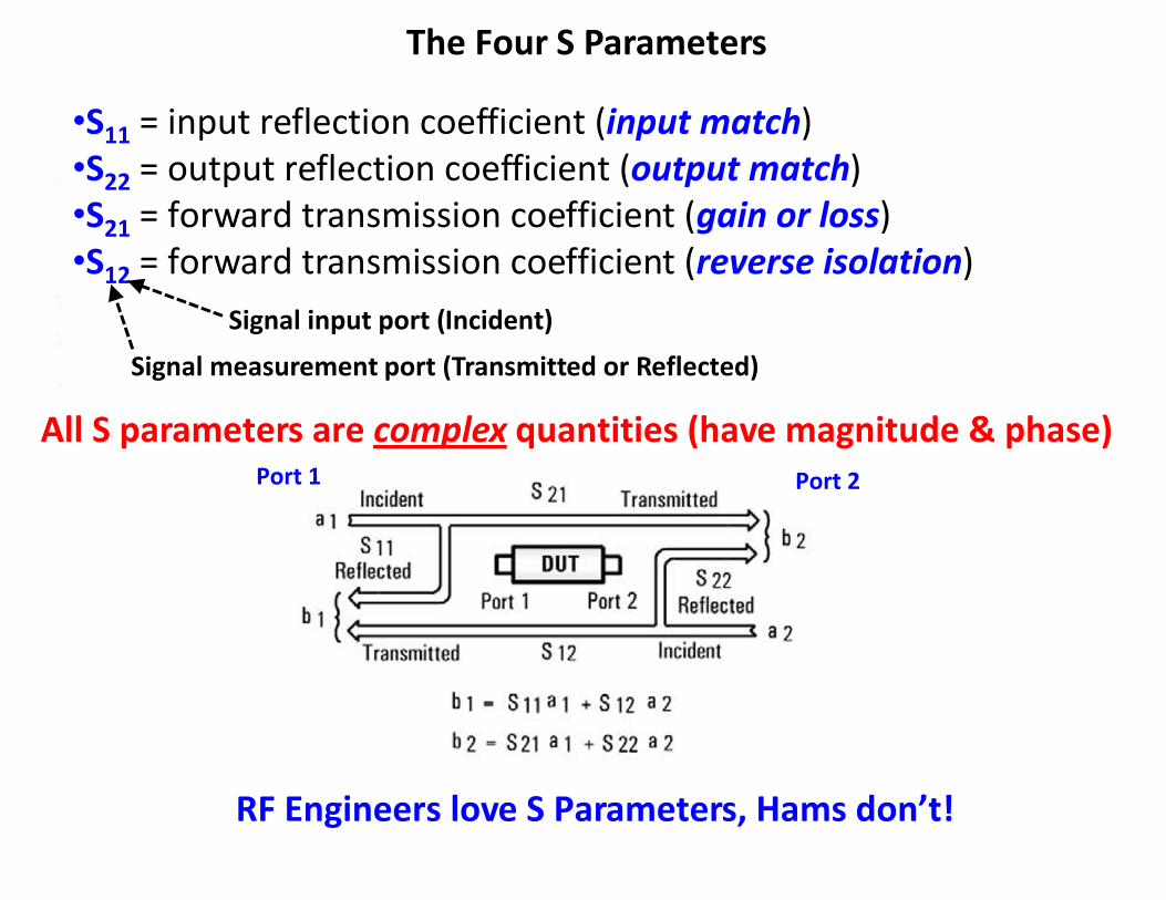
The Four S Parameters
•S11 = input reflection coefficient (input match)•S22 = output reflection coefficient (output match)•S21 = forward transmission coefficient (gain or loss)•S12 = forward transmission coefficient (reverse isolation)
All S parameters are complex quantities (have magnitude & phase)
Signal input port (Incident)
Signal measurement port (Transmitted or Reflected)
RF Engineers love S Parameters, Hams don’t!
Port 1 Port 2
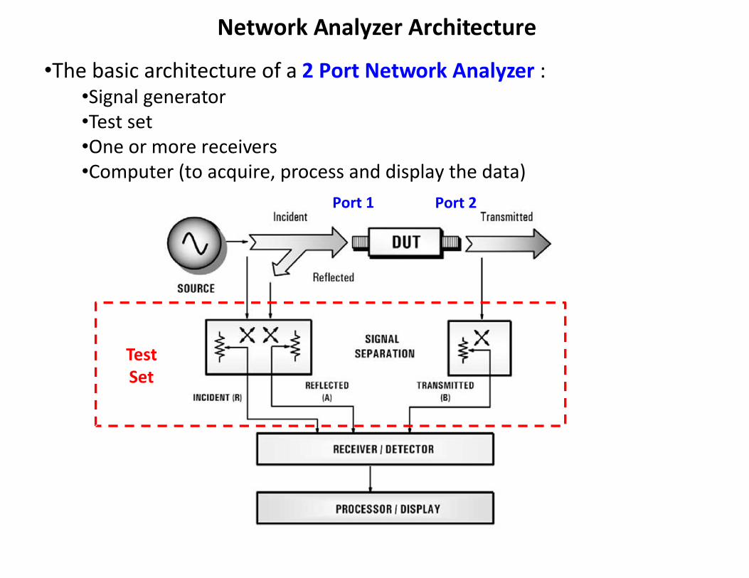
Network Analyzer Architecture
•The basic architecture of a 2 Port Network Analyzer :•Signal generator•Test set•One or more receivers•Computer (to acquire, process and display the data)
TestSet
Port 1 Port 2
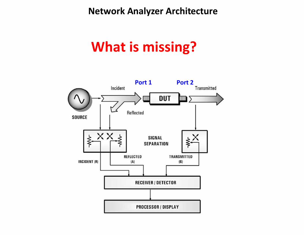
Network Analyzer Architecture
What is missing?
Port 1 Port 2
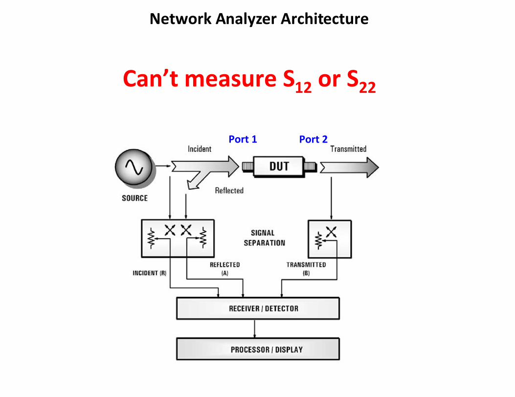
Network Analyzer Architecture
Can’t measure S12 or S22
Port 1 Port 2
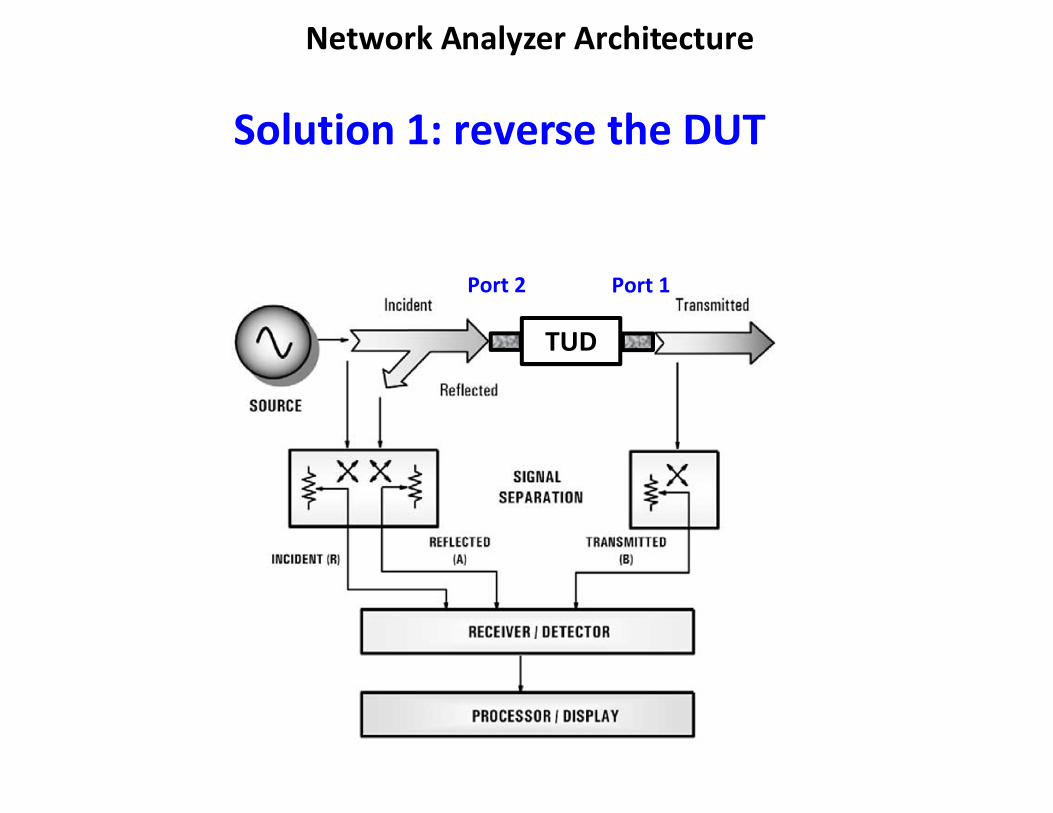
Network Analyzer Architecture
Solution 1: reverse the DUT
TUD
Port 2 Port 1
DUTTestSet
Receivers (2)
Computer
SigGen
Receivers (2)
TestSet
RefOsc
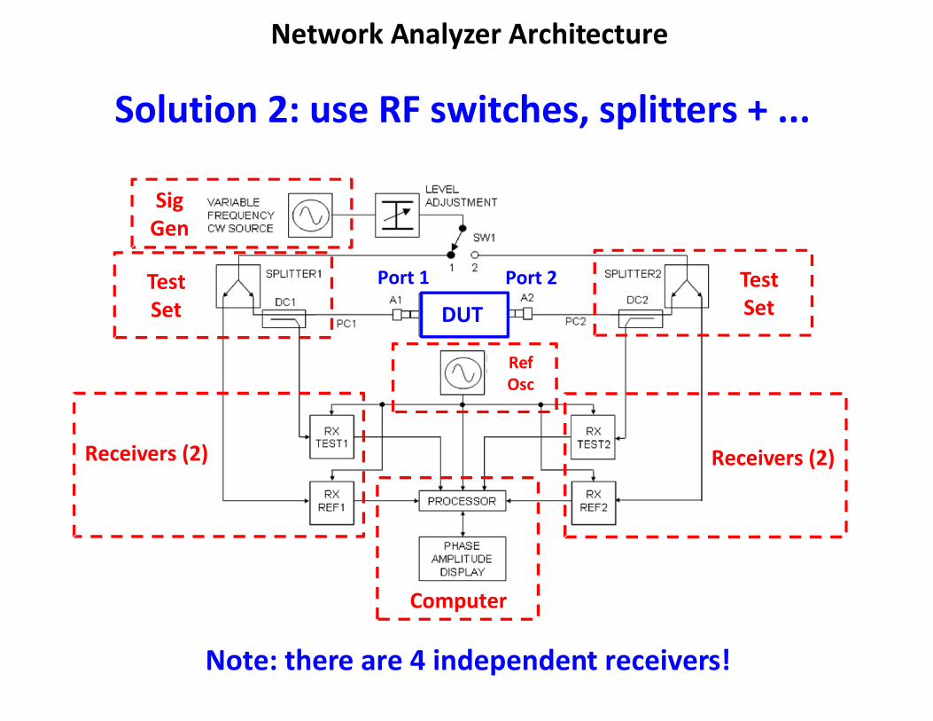
Network Analyzer Architecture
Solution 2: use RF switches, splitters + ...
Note: there are 4 independent receivers!
Port 1 Port 2
Types of Network Analyzers
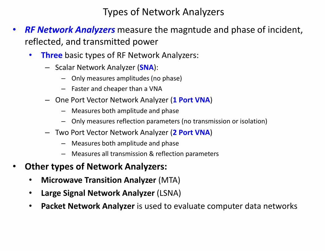
• RF Network Analyzers measure the magntude and phase of incident, reflected, and transmitted power• Three basic types of RF Network Analyzers:
– Scalar Network Analyzer (SNA):– Only measures amplitudes (no phase)– Faster and cheaper than a VNA
– One Port Vector Network Analyzer (1 Port VNA)– Measures both amplitude and phase– Only measures reflection parameters (no transmission or isolation)
– Two Port Vector Network Analyzer (2 Port VNA)– Measures both amplitude and phase– Measures all transmission & reflection parameters
• Other types of Network Analyzers:• Microwave Transition Analyzer (MTA)• Large Signal Network Analyzer (LSNA)• Packet Network Analyzer is used to evaluate computer data networks
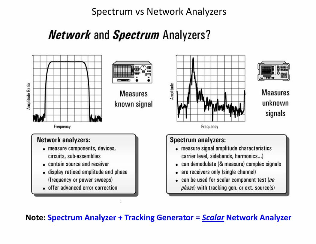
Spectrum vs Network Analyzers
Note: Spectrum Analyzer + Tracking Generator = Scalar Network Analyzer
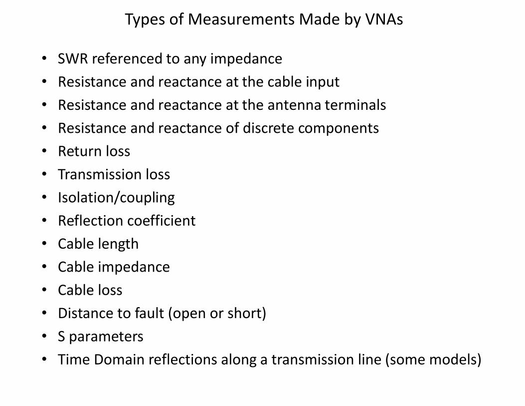
Types of Measurements Made by VNAs
• SWR referenced to any impedance• Resistance and reactance at the cable input• Resistance and reactance at the antenna terminals• Resistance and reactance of discrete components• Return loss• Transmission loss• Isolation/coupling• Reflection coefficient• Cable length• Cable impedance• Cable loss• Distance to fault (open or short)• S parameters• Time Domain reflections along a transmission line (some models)
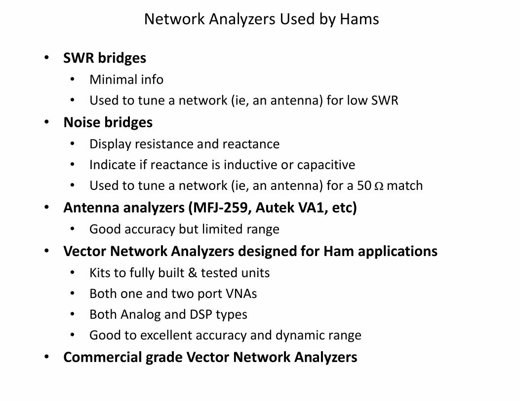
Network Analyzers Used by Hams
• SWR bridges• Minimal info• Used to tune a network (ie, an antenna) for low SWR
• Noise bridges• Display resistance and reactance• Indicate if reactance is inductive or capacitive• Used to tune a network (ie, an antenna) for a 50 W match
• Antenna analyzers (MFJ-259, Autek VA1, etc)• Good accuracy but limited range
• Vector Network Analyzers designed for Ham applications• Kits to fully built & tested units• Both one and two port VNAs• Both Analog and DSP types• Good to excellent accuracy and dynamic range
• Commercial grade Vector Network Analyzers
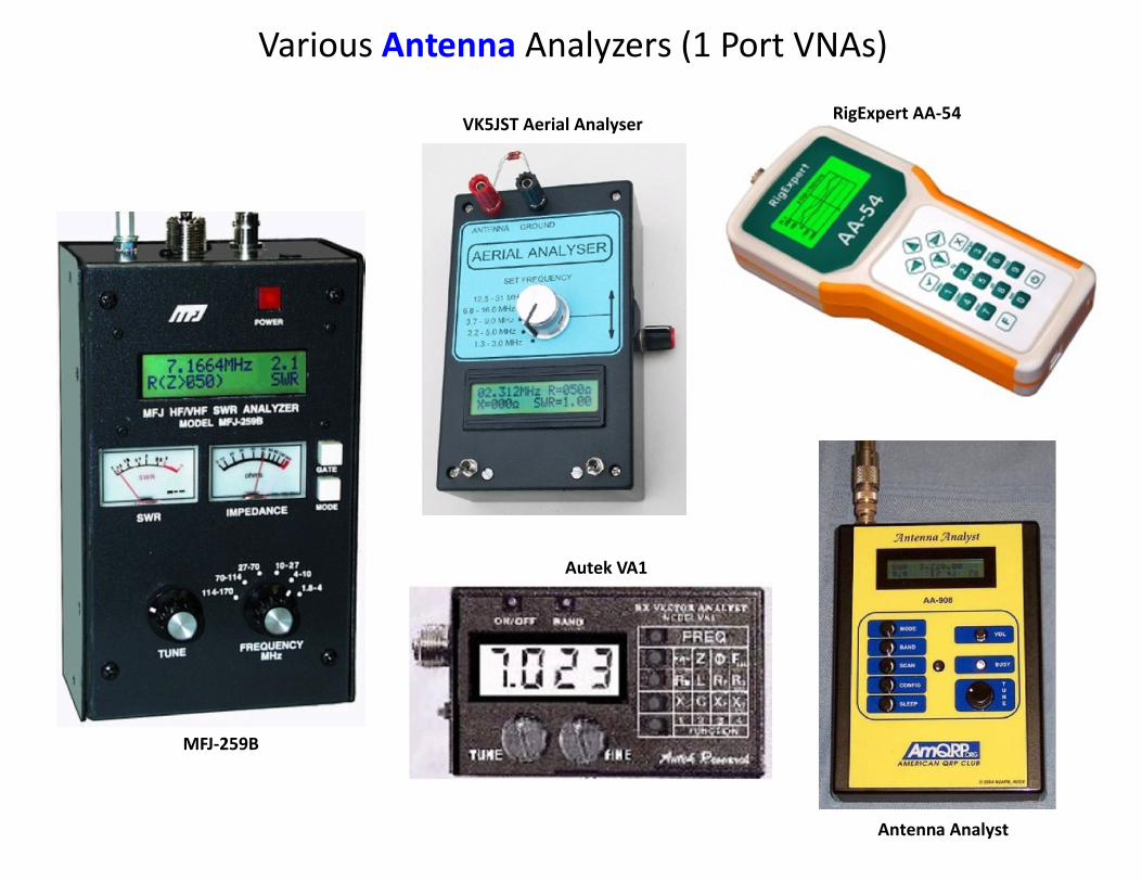
Various Antenna Analyzers (1 Port VNAs)
MFJ-259B
Antenna Analyst
VK5JST Aerial Analyser
Autek VA1
RigExpert AA-54
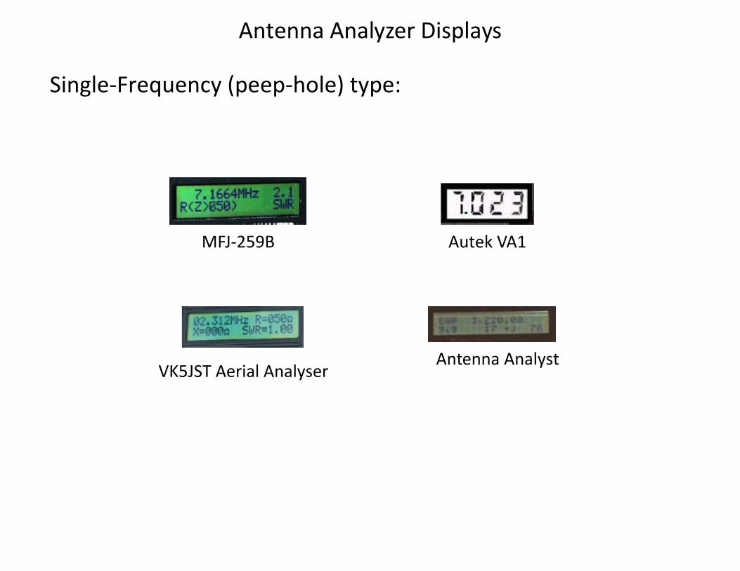
Antenna Analyzer Displays
MFJ-259B Autek VA1
Antenna AnalystVK5JST Aerial Analyser
Single-Frequency (peep-hole) type:
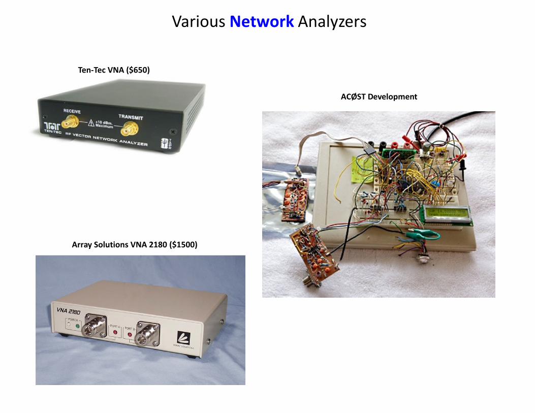
Various Network Analyzers
Array Solutions VNA 2180 ($1500)
ACØST Development
Ten-Tec VNA ($650)
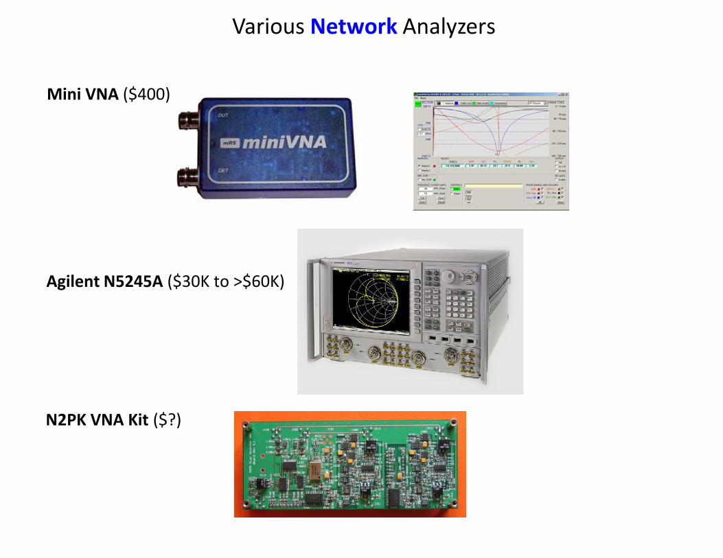
Mini VNA ($400)
N2PK VNA Kit ($?)
Agilent N5245A ($30K to >$60K)
Various Network Analyzers
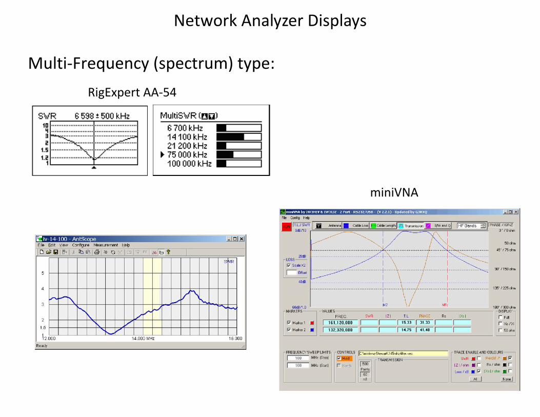
Network Analyzer Displays
Multi-Frequency (spectrum) type:
miniVNA
RigExpert AA-54
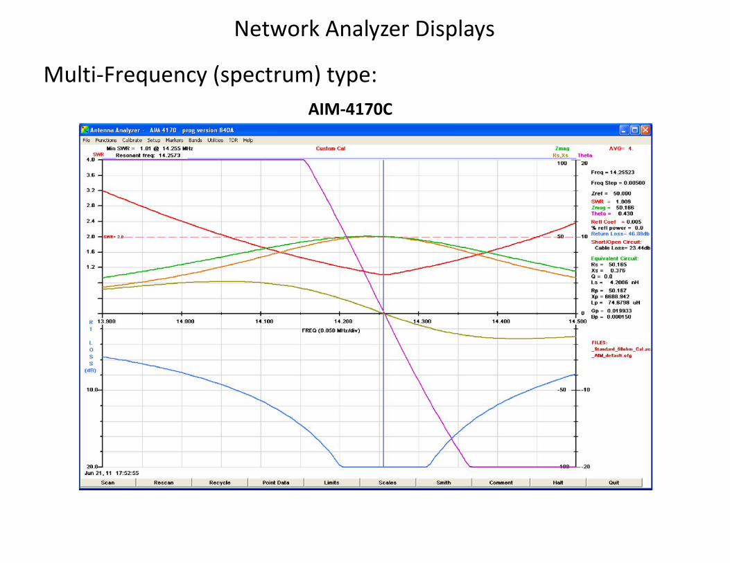
Network Analyzer Displays
AIM-4170C
Multi-Frequency (spectrum) type:
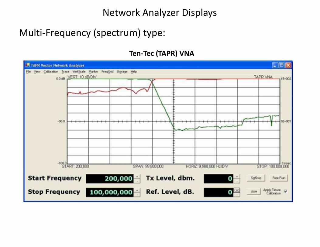
Ten-Tec (TAPR) VNA
Network Analyzer Displays
Multi-Frequency (spectrum) type:
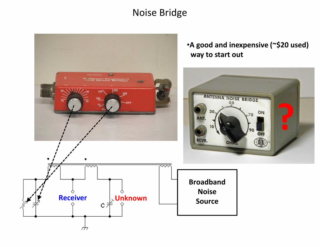
Noise Bridge
BroadbandNoise
SourceReceiver Unknown
•A good and inexpensive (~$20 used)way to start out
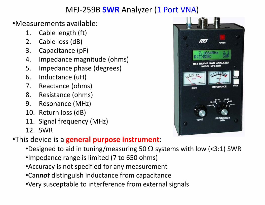
MFJ-259B SWR Analyzer (1 Port VNA)
•Measurements available:1. Cable length (ft)2. Cable loss (dB)3. Capacitance (pF)4. Impedance magnitude (ohms)5. Impedance phase (degrees)6. Inductance (uH)7. Reactance (ohms)8. Resistance (ohms)9. Resonance (MHz)10. Return loss (dB)11. Signal frequency (MHz)12. SWR
•This device is a general purpose instrument:•Designed to aid in tuning/measuring 50 W systems with low (<3:1) SWR•Impedance range is limited (7 to 650 ohms)•Accuracy is not specified for any measurement•Cannot distinguish inductance from capacitance•Very susceptable to interference from external signals
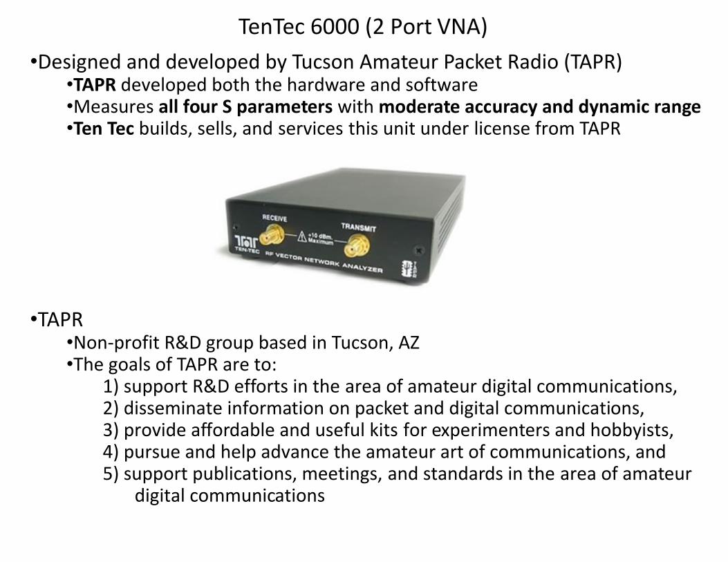
•Designed and developed by Tucson Amateur Packet Radio (TAPR)•TAPR developed both the hardware and software•Measures all four S parameters with moderate accuracy and dynamic range•Ten Tec builds, sells, and services this unit under license from TAPR
•TAPR•Non-profit R&D group based in Tucson, AZ•The goals of TAPR are to:
1) support R&D efforts in the area of amateur digital communications,2) disseminate information on packet and digital communications,3) provide affordable and useful kits for experimenters and hobbyists,4) pursue and help advance the amateur art of communications, and5) support publications, meetings, and standards in the area of amateur
digital communications
TenTec 6000 (2 Port VNA)
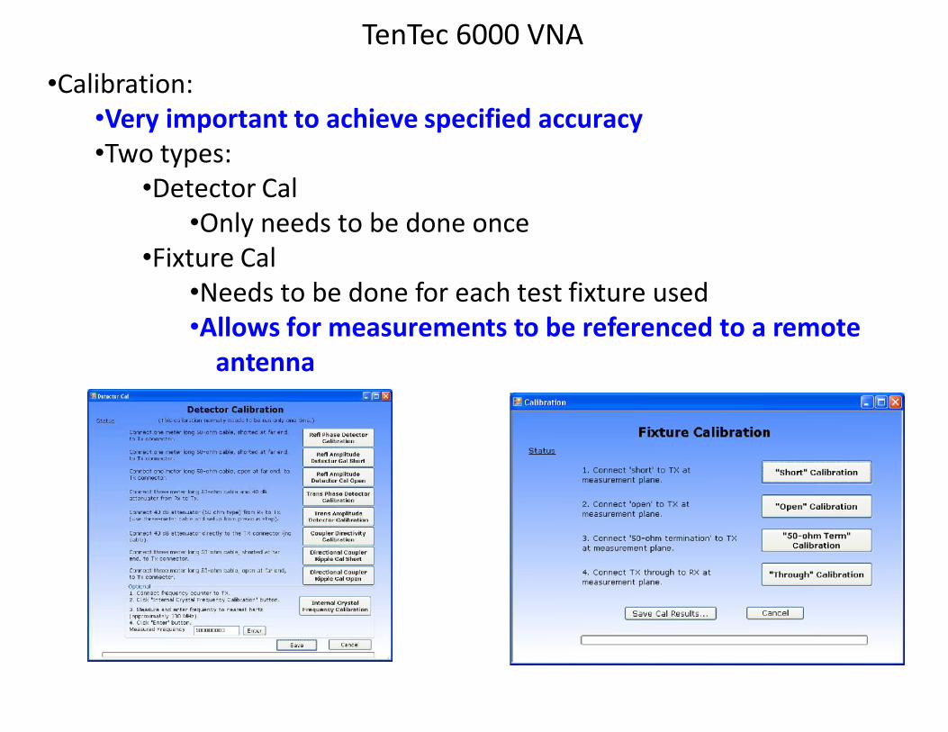
•Calibration:•Very important to achieve specified accuracy•Two types:
•Detector Cal•Only needs to be done once
•Fixture Cal•Needs to be done for each test fixture used•Allows for measurements to be referenced to a remote
antenna
TenTec 6000 VNA
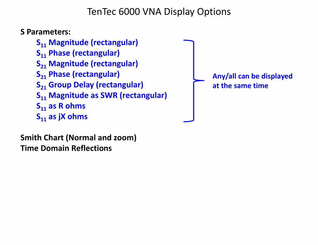
TenTec 6000 VNA Display Options
S Parameters:S11 Magnitude (rectangular)S11 Phase (rectangular)S21 Magnitude (rectangular)S21 Phase (rectangular)S21 Group Delay (rectangular)S11 Magnitude as SWR (rectangular)S11 as R ohmsS11 as jX ohms
Smith Chart (Normal and zoom)Time Domain Reflections
Any/all can be displayedat the same time
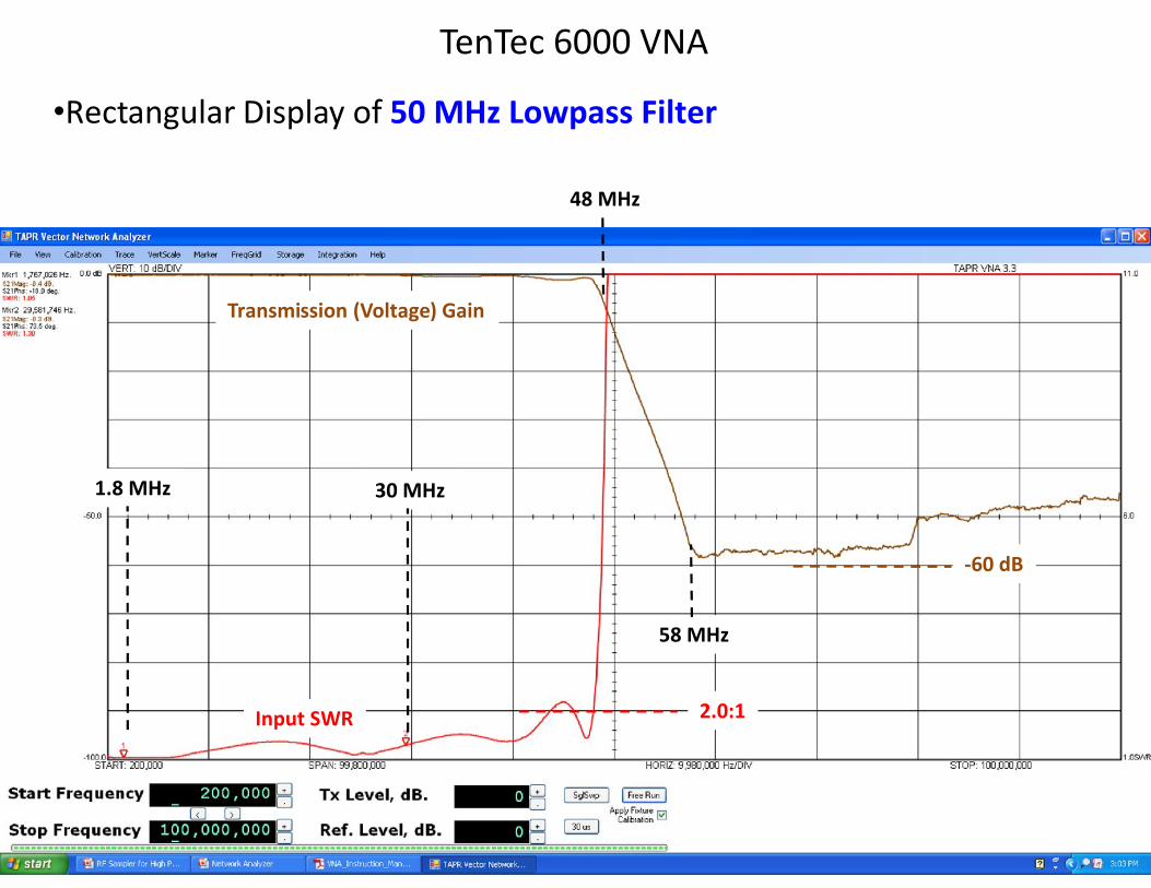
TenTec 6000 VNA
•Rectangular Display of 50 MHz Lowpass Filter
2.0:1
-60 dB
1.8 MHz 30 MHz
48 MHz
58 MHz
Transmission (Voltage) Gain
Input SWR
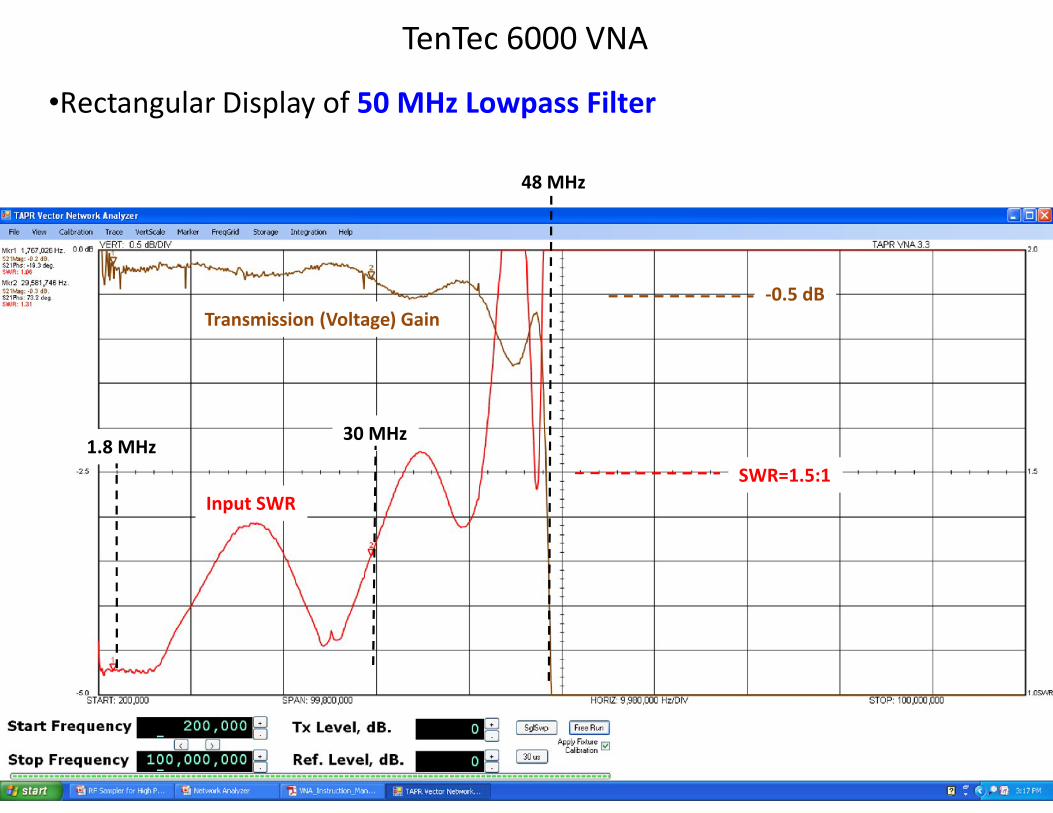
TenTec 6000 VNA
SWR=1.5:1
-0.5 dB
1.8 MHz30 MHz
48 MHz
•Rectangular Display of 50 MHz Lowpass Filter
Input SWR
Transmission (Voltage) Gain
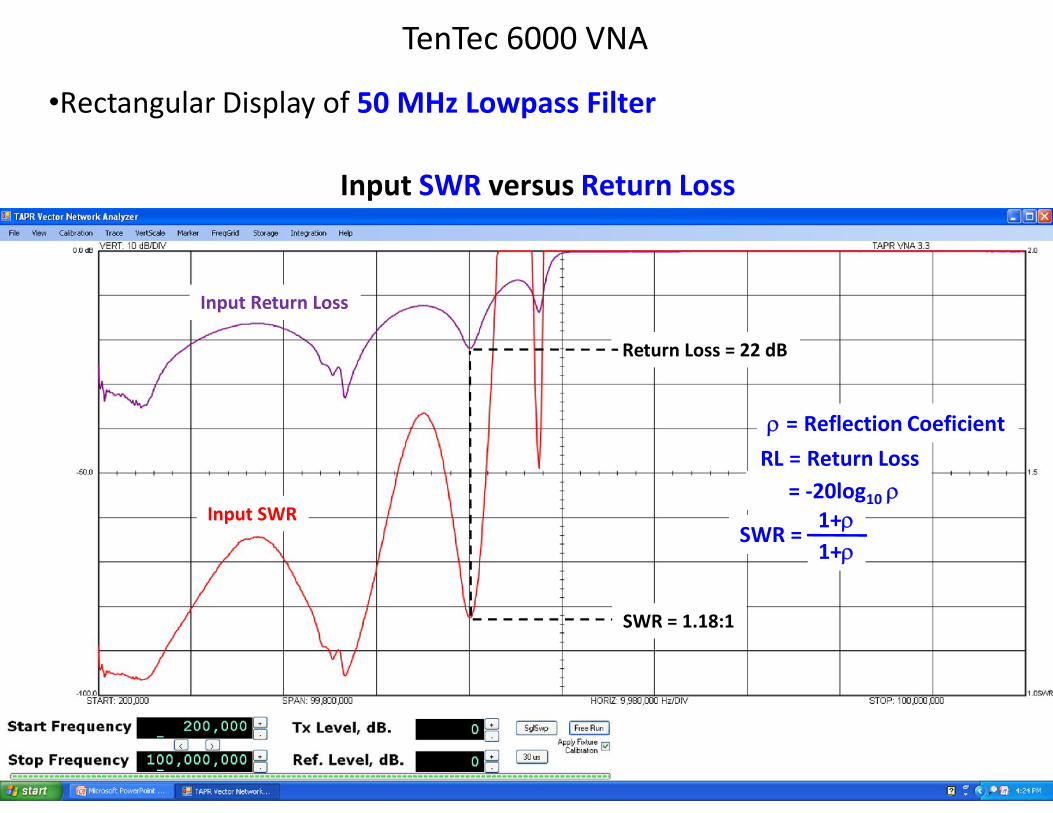
TenTec 6000 VNA
•Rectangular Display of 50 MHz Lowpass Filter
Input SWR versus Return Loss
Return Loss = 22 dB
SWR = 1.18:1
Input SWR
Input Return Loss
SWR =1+r1+r
r = Reflection CoeficientRL = Return Loss
= -20log10 r
TenTec 6000 VNA
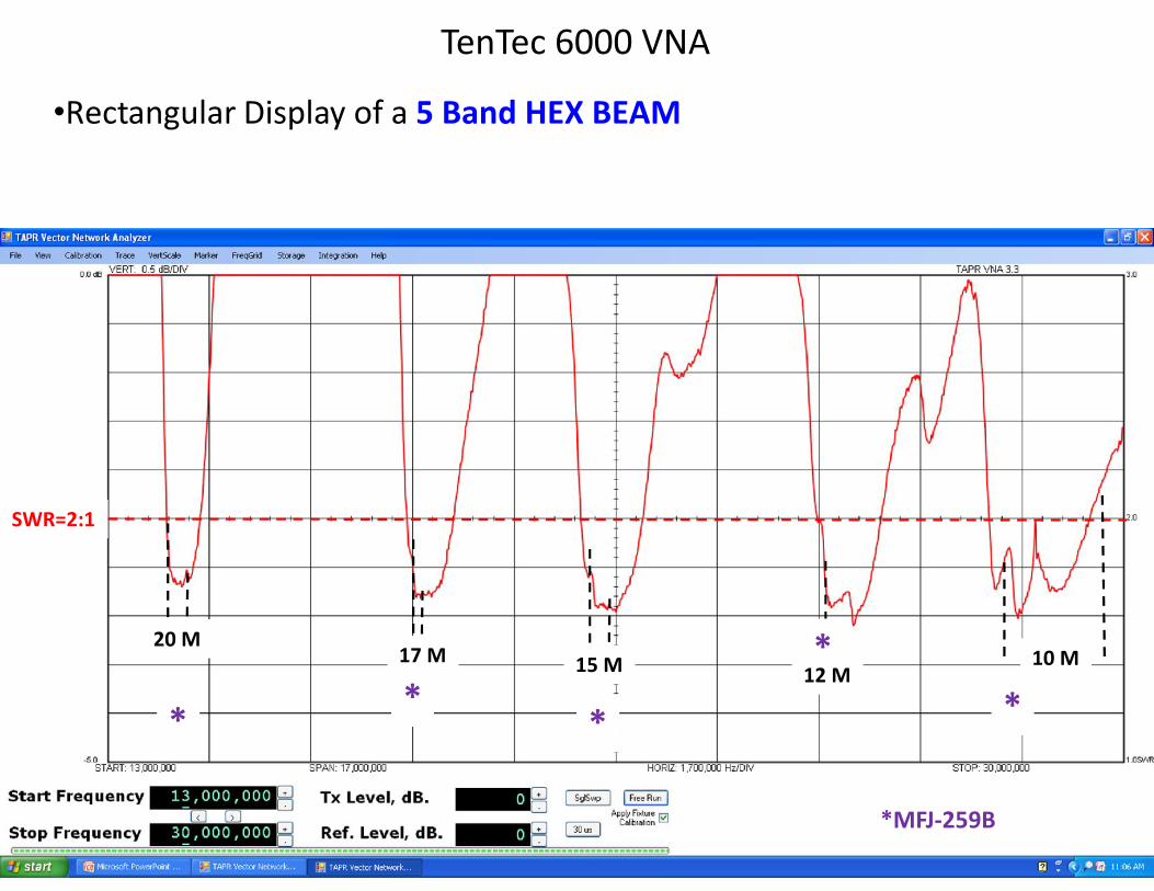
•Rectangular Display of a 5 Band HEX BEAM
SWR=2:1
20 M17 M 15 M 10 M
*MFJ-259B
**
*
**
12 M
Resistance = 50W
Resistance = 0W
Resistance = 100W
Reactance = 0W
Reactance = -50W
Reactance = +50W
TenTec 6000 VNA
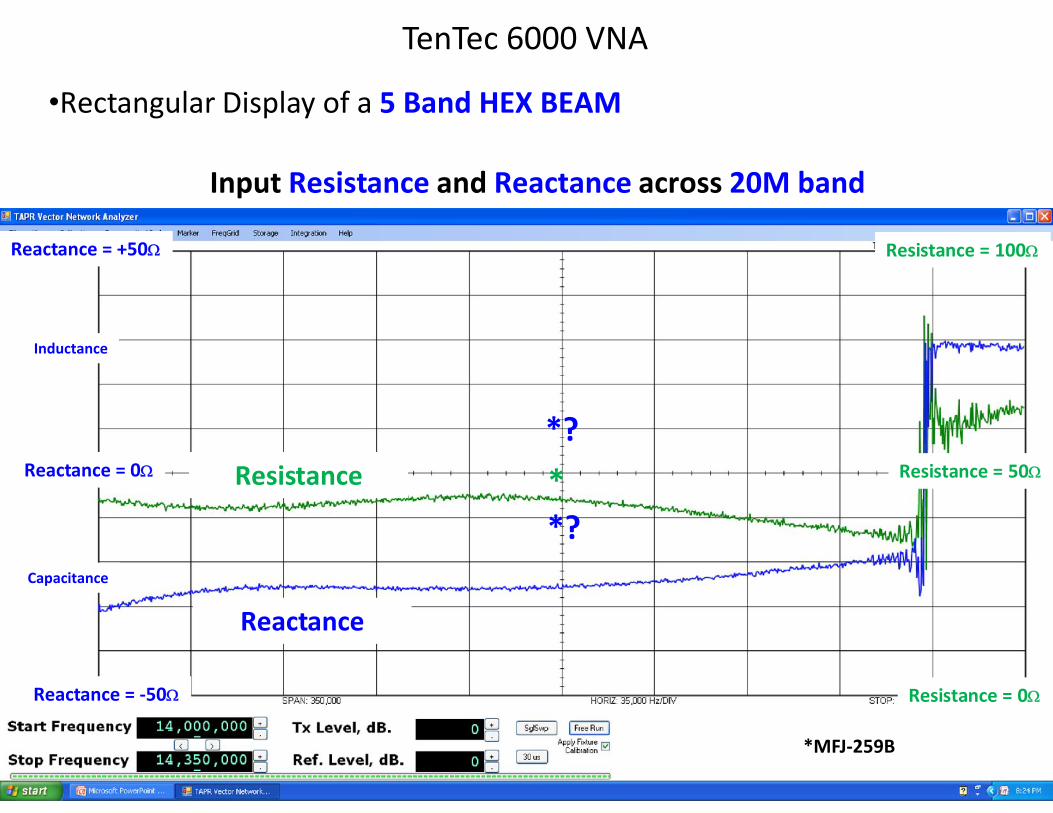
•Rectangular Display of a 5 Band HEX BEAM
Input Resistance and Reactance across 20M band
Resistance
Reactance
*MFJ-259B
**?
*?
Inductance
Capacitance
TenTec 6000 VNA
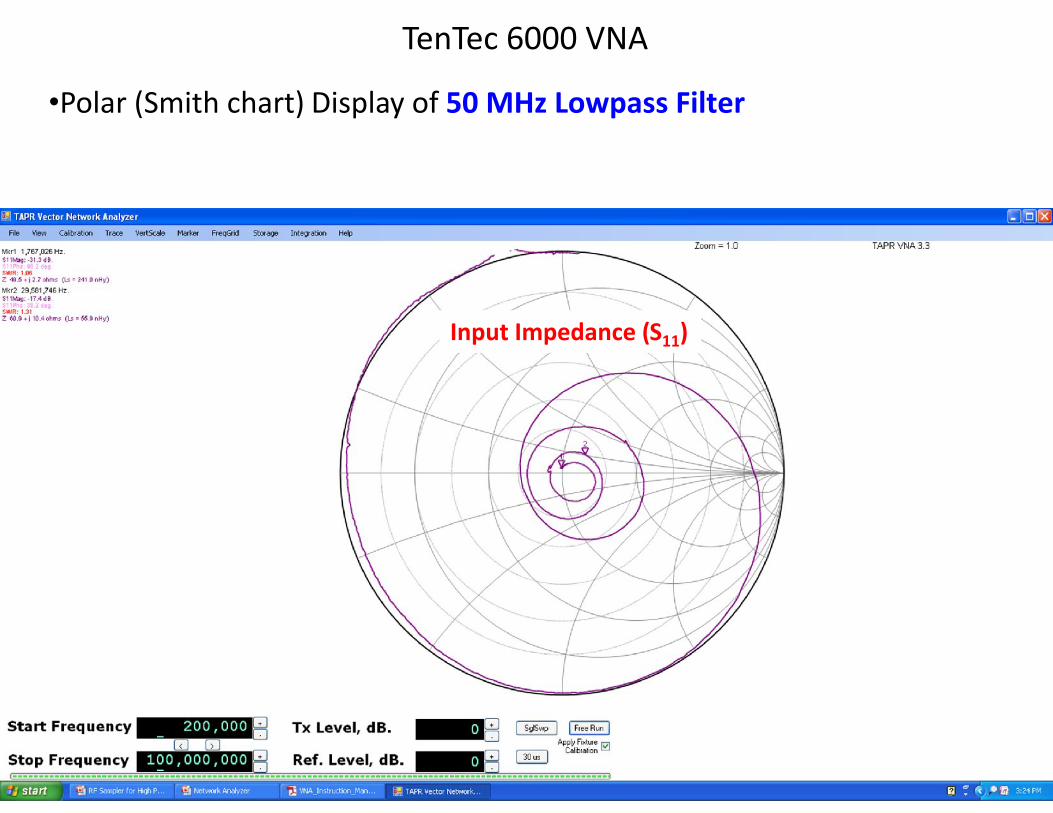
•Polar (Smith chart) Display of 50 MHz Lowpass Filter
Input Impedance (S11)
TenTec 6000 VNA
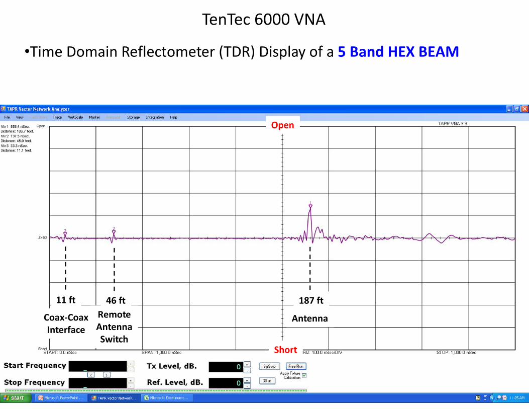
•Time Domain Reflectometer (TDR) Display of a 5 Band HEX BEAM
AntennaRemoteAntennaSwitch
Coax-CoaxInterface
11 ft 46 ft 187 ft
Open
Short
TenTec 6000 VNA
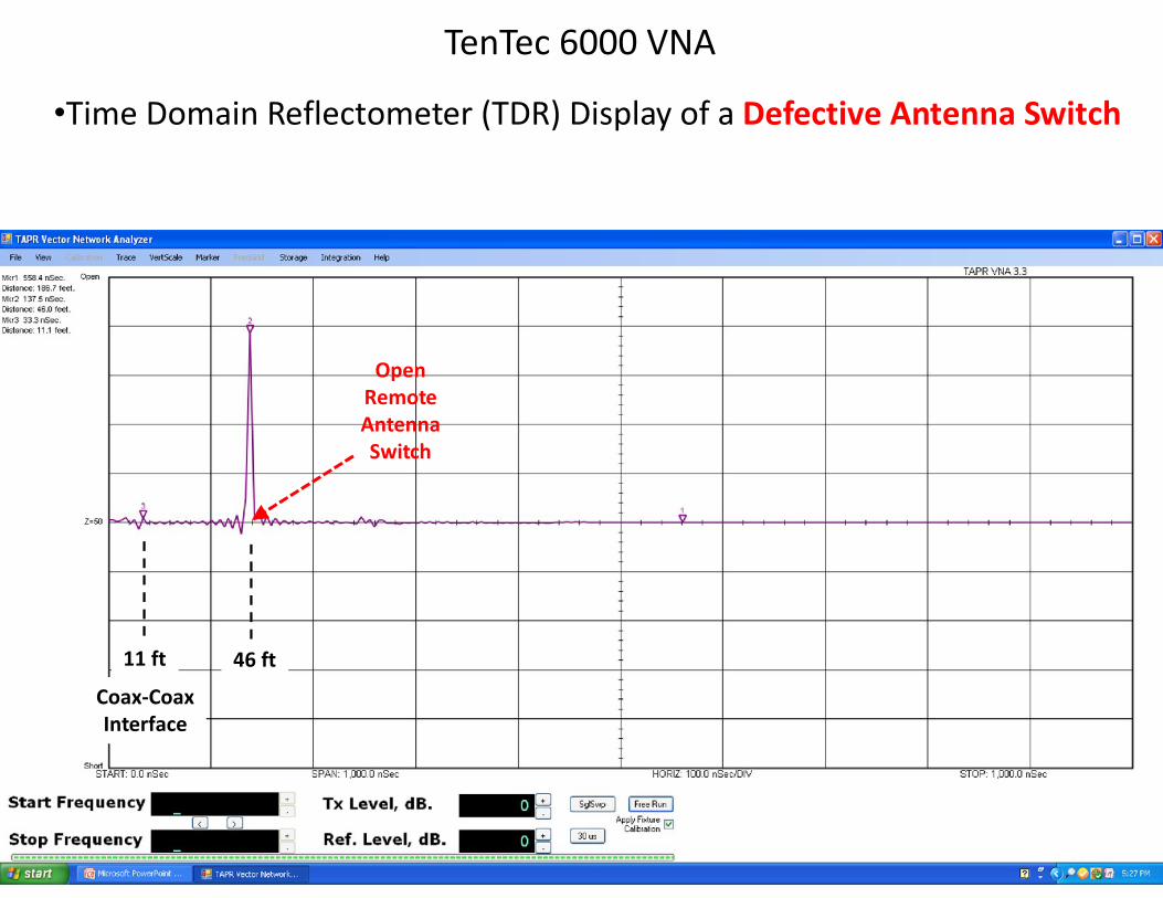
•Time Domain Reflectometer (TDR) Display of a Defective Antenna Switch
OpenRemoteAntennaSwitch
11 ft 46 ft
Coax-CoaxInterface
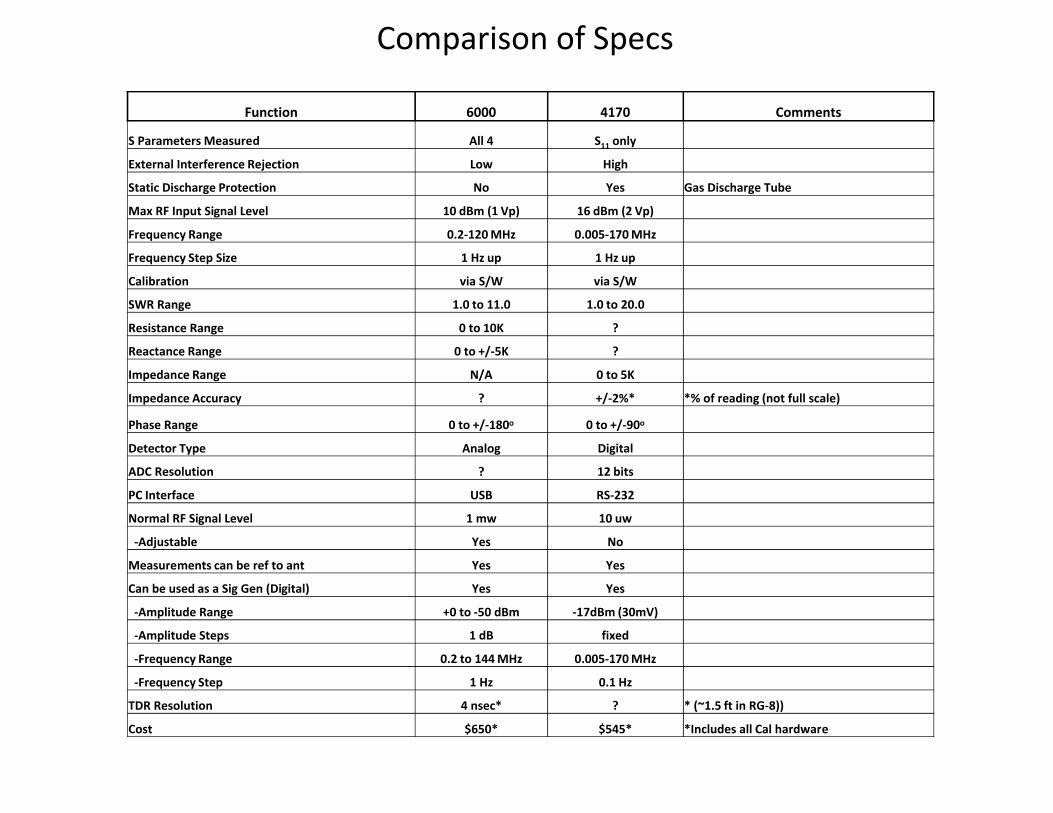
Comparison of Specs
Function 6000 4170 Comments
S Parameters Measured All 4 S11 only
External Interference Rejection Low High
Static Discharge Protection No Yes Gas Discharge Tube
Max RF Input Signal Level 10 dBm (1 Vp) 16 dBm (2 Vp)
Frequency Range 0.2-120 MHz 0.005-170 MHz
Frequency Step Size 1 Hz up 1 Hz up
Calibration via S/W via S/W
SWR Range 1.0 to 11.0 1.0 to 20.0
Resistance Range 0 to 10K ?
Reactance Range 0 to +/-5K ?
Impedance Range N/A 0 to 5K
Impedance Accuracy ? +/-2%* *% of reading (not full scale)
Phase Range 0 to +/-180o 0 to +/-90o
Detector Type Analog Digital
ADC Resolution ? 12 bits
PC Interface USB RS-232
Normal RF Signal Level 1 mw 10 uw
-Adjustable Yes No
Measurements can be ref to ant Yes Yes
Can be used as a Sig Gen (Digital) Yes Yes
-Amplitude Range +0 to -50 dBm -17dBm (30mV)
-Amplitude Steps 1 dB fixed
-Frequency Range 0.2 to 144 MHz 0.005-170 MHz
-Frequency Step 1 Hz 0.1 Hz
TDR Resolution 4 nsec* ? * (~1.5 ft in RG-8))
Cost $650* $545* *Includes all Cal hardware
AIM-4170 Antenna Analyzer(Network Analyzer)
Presentation for the 285-TechConnect Meeting
Dale Keller, ACØST
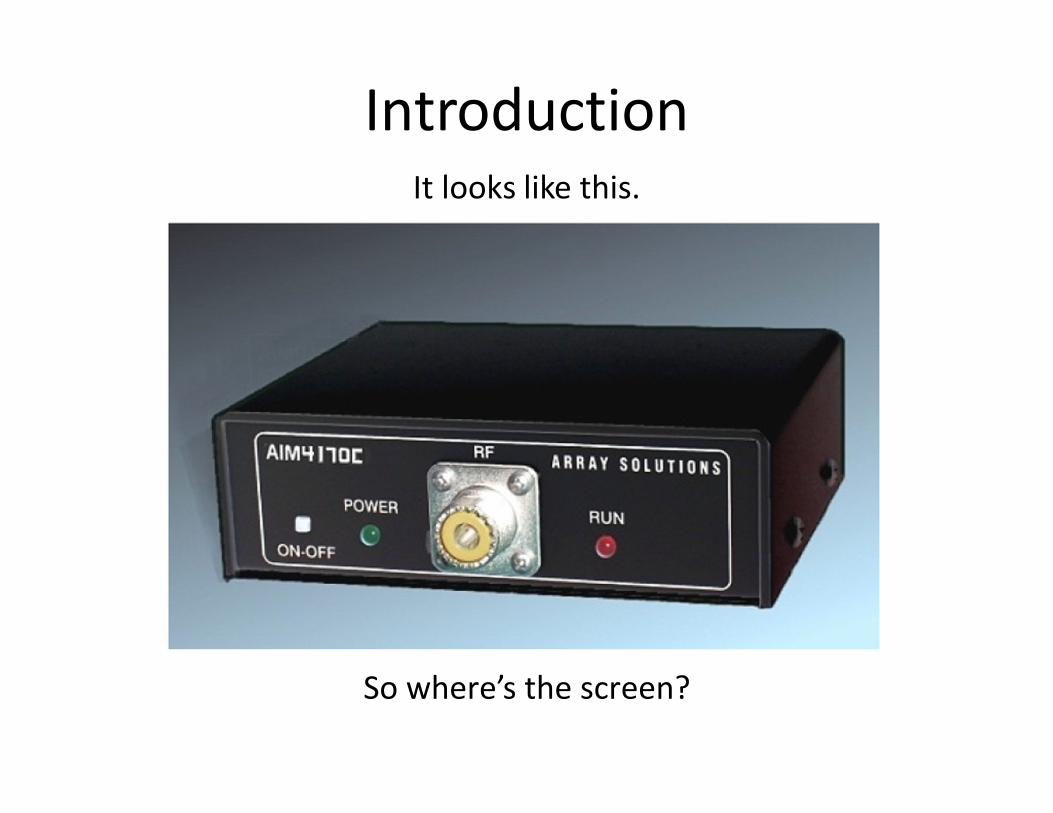
Introduction
So where’s the screen?
It looks like this.
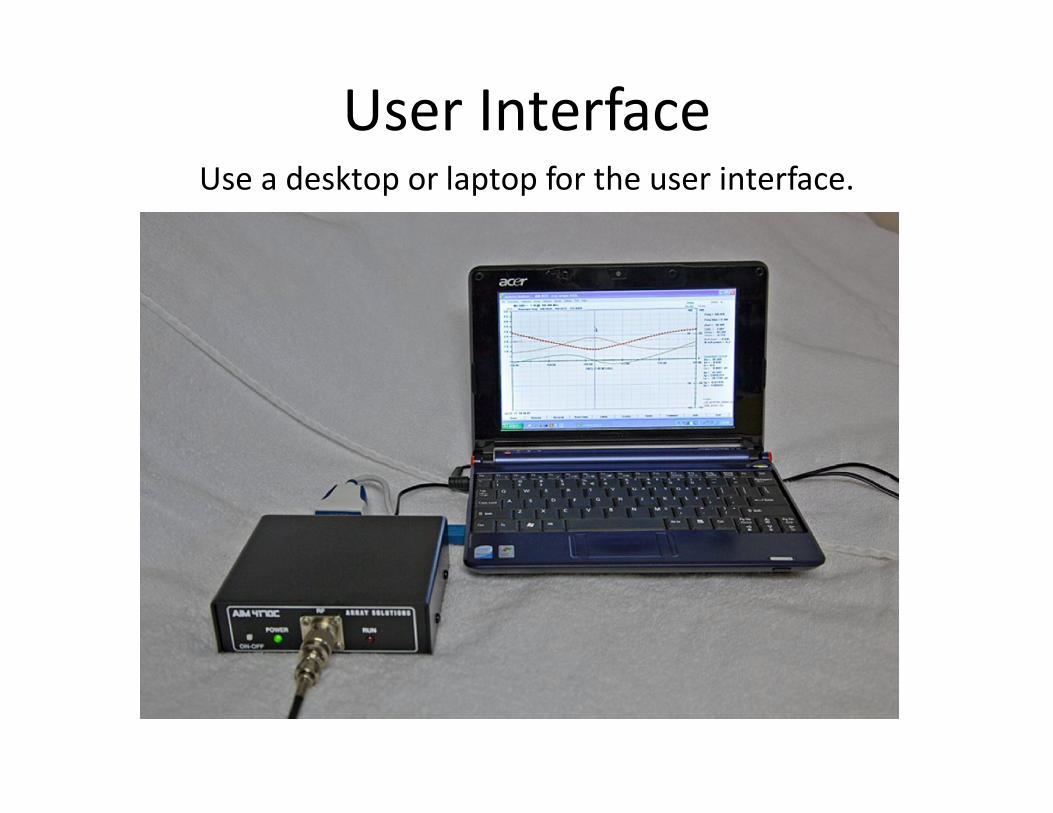
User InterfaceUse a desktop or laptop for the user interface.
General Information
• This is more of a graphical network analyzer than an antenna analyzer.
• Instead of checking a single frequency controlled by your hand on a knob, it sweeps a frequency range and displays the data on a graph.
• Covers 0.1 to 170 MHz.• $545.00
General Info (continued)
• This is probably the lowest priced network analyzer available, but compares very well with much more expensive lab equipment.
• Another model, AIMuhf ($$) goes up to 1 GHz.• Array Solutions also makes a two-port
VNA2180 Vector Network Analyzer ($$$).
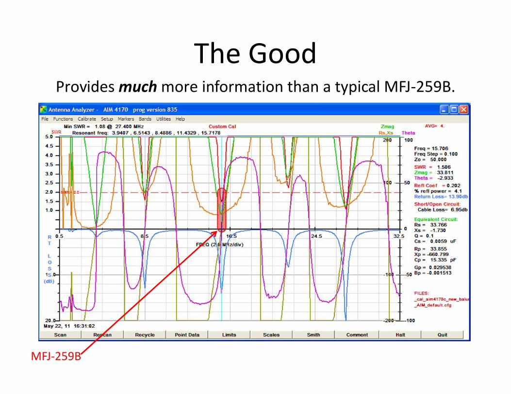
The GoodProvides much more information than a typical MFJ-259B.
MFJ-259B
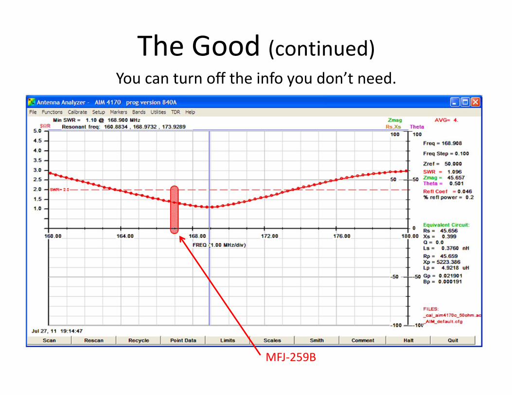
The Good (continued)You can turn off the info you don’t need.
MFJ-259B
The Good (continued)
• High tolerance to external signals (AM broadcast interference, 60 Hz induced currents, etc).
• Can use a broadcast-band filter and calibrate around it.• Calibrate to the "plane of measurement" - the point at
which the actual measurement is made.• Custom Calibration for cables, filters, baluns, etc.
(plane of measurement, or measurement reference point).
• Accuracy: QST review said "the accuracy is exceptional and caused us to go back and check the calibration of our reference loads“. It compares very well to laboratory grade test instruments.
The Good (continued)
• Measure crystals, inductors, capacitors.• Has a TDR function - find electrical length of
coax, or a break point.• Display a Smith Chart.• "Live" mode (Point Data) like MFJ-259B.• Free software updates.
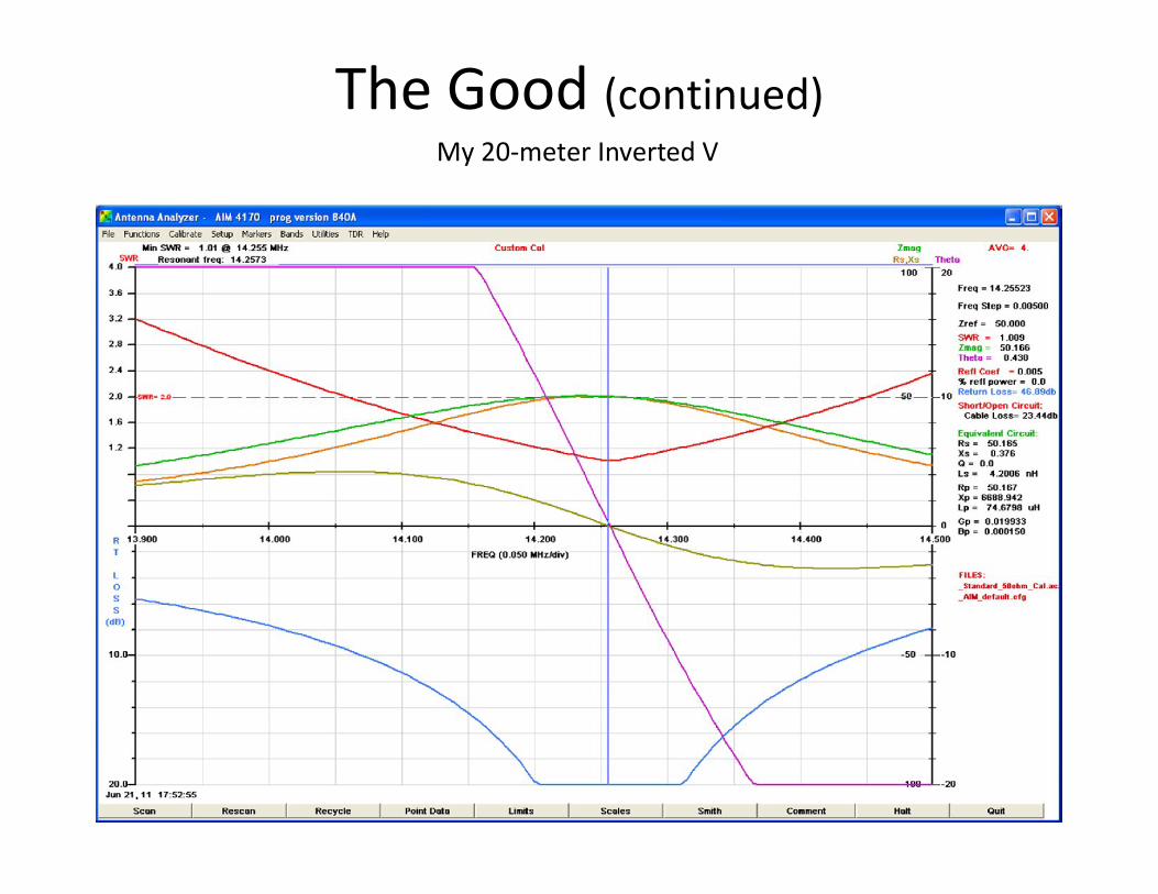
The Good (continued)My 20-meter Inverted V
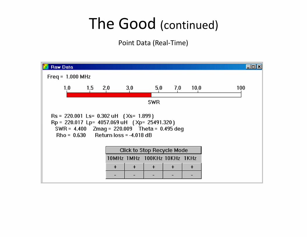
The Good (continued)Point Data (Real-Time)
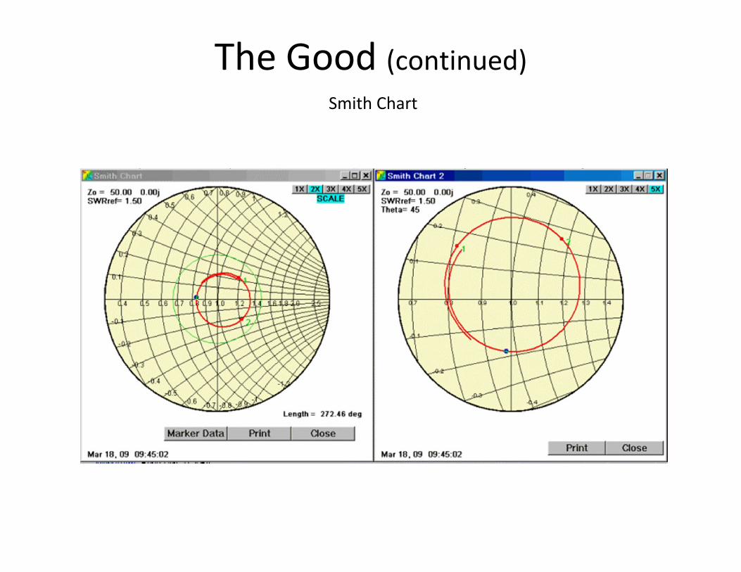
The Good (continued)Smith Chart
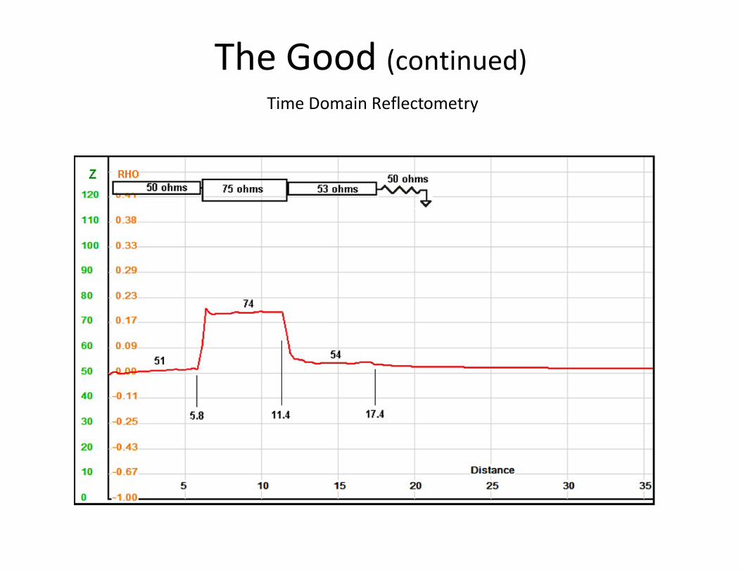
The Good (continued)Time Domain Reflectometry
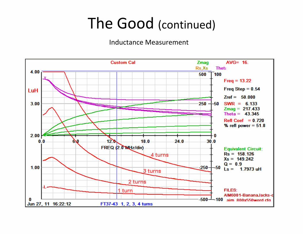
The Good (continued)Inductance Measurement
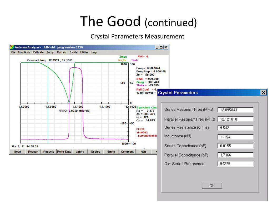
The Good (continued)Crystal Parameters Measurement
The Bad
• NOT much to complain about.• The manual is good, but doesn’t show everything,
so you have to Google around for hints.• Stray capacitance to ground is a problem when
measuring high impedance circuits (like an end-fed half-wave antenna).Make short power and serial cables, run it on battery power, place it on a wooden table. It will still have more stray capacitance than a handheld instrument. My EFHWA should show >5K ohms, but gets flakey above about 2K ohms.

The Bad (continued)Not as "handy" as MFJ-259B. It takes up more room and has more parts. It’s fine in the shop, but not as handy on the tower or in the field.

The Ugly
Conclusion
The best antenna analyzer is actually two analyzers -- one of each: a network analyzer like the AIM-4170, and a handheld unit like the MFJ-259B.
• W5BIG Bob Clunn website (designer, software developer, general information) http://www.w5big.com/
• Ordering website http://www.arraysolutions.com/Products/AIM4170.htm
• Ian Wade, G3NWR, has a PowerPoint presentation at http://homepage.ntlworld.com/wadei/aim4170.htm


![RF circuits design 1 - ue.pwr.wroc.pl€¦ · RF circuitsdesign Grzegorz Beziuk Introduction. Basic definitions and parameters References [1] TietzeU., Schenk C., Electronic circuits](https://static.fdocuments.net/doc/165x107/5ec4443c30672539bf67bf15/rf-circuits-design-1-uepwrwrocpl-rf-circuitsdesign-grzegorz-beziuk-introduction.jpg)