MEASURING C PERMITTIVITY AND PERMS:., L TV AT ... - … · PERMITTIVITY AND PERMS:.," L TV ... This...
26
.:. MEASURING C :.'··PL "". PERMITTIVITY AND PERMS:.," L TV AT RF AND MICROWAVE:' .#.' . • . .. . Bob Dildine Yokogawa Hewlett-Packard 29-21, Takaido-Higashi 3-Chome, Suginami-ku, Tokyo, 168 Japan RF & Microwave Measurement Symposium and Exhibition F'i;' HEWLETT PACKARD www.HPARCHIVE.com
-
Upload
nguyenkhuong -
Category
Documents
-
view
219 -
download
2
Transcript of MEASURING C PERMITTIVITY AND PERMS:., L TV AT ... - … · PERMITTIVITY AND PERMS:.," L TV ... This...

.:.
MEASURING C :.'··PL "".PERMITTIVITY AND PERMS:.," L TV
AT RF AND MICROWAVE:' FRE,,~~",UE'NC~ES.#.' . •. ... ..~
Bob DildineYokogawa Hewlett-Packard
29-21, Takaido-Higashi 3-Chome,Suginami-ku, Tokyo, 168 Japan
RF & MicrowaveMeasurementSymposiumandExhibition
F'i;' HEWLETT~~ PACKARD
www.HPARCHIVE.com

r
ABSTRACT
This paper concerns the measurement of complex permittivity and permeability in bulkmaterials at high frequencies. A survey of common measurement methods is presented, with adiscussion of the strengths and weaknesses of each technique. A short discussion ofmeasurement errors and uncertainties is included.
AUTHOR
Bob Dildine, R&D Engineer, HP Network Measurements Division, Santa Rosa, Ca. BSElectrical Engineering (1967), San Diego State College and MS Electrical Engineering andComputer Science (1973), University of California, Berkeley. The author has been with HPsince 1973, and has spent most of his career as a member of the R&D team developing theHP 8510 microwave network analyzer. In 1980 he became project manager for the HP 85118515 test sets for the HP 8510, and was involved with the extension of the HP 8510 tomillimter-wave frequencies. He is currently on assignment at YHP's Project Center in Japan,where his research includes high-frequency techniques for measuring permittivity andpermeability in bulk materials.
3
www.HPARCHIVE.com

MEASURING COMPLEX PERMITTIVITYAND PERMEABILITY AT RF AND
MICROWAVE FREQUENCIES
In this paper, common methods of measuring thecomplex permittivity and permeability of dielectricmaterials at RF and microwave frequencies will bediscussed. Accuracy considerations will be discussed andan error analysis will be performed for the S-parametermethod. Methods of making measurements onsv.perconductors will not be covered.
.umc.:... 00.1..
y ...
BawWC-Padt ..
U .. lIICao1l'AUKKAlUIDfl:Il1'
n".oln'.....ulDJlDDmoll
8371
.. ApplicationsMaterial PropertiesMeasurement MethodsSources of ErrorSummary
8372
We will start off with a discussion of the reasonsto measure the electrical properties of materials,and quickly review the definitions of these electricalproperties. Next, we'll survey the most common methodsof measuring the electrical properties of ma.terials,including their advantages and disadvantages. We'llconclude with a brief discussion of measurement errors.
Let's begin, then, with the reasons one might want tomeasure the electrical properties of materials.
c
RIEASONS TO MEASURE ELECTRICALPROPERTIES OF MATERIALS-- Facilitate Design and Modeling
• Substrates• Filter materials• Magnetic cores• Absorber materials
• RF losses• Packaging materials• Microwaveable food
8373
5
Materials are used in a wide variety of applications inelectricity and electronics. Some applications includeinsulators, magnetic cores, substrates, absorbingmaterials for electromagnetic energy, and packagingmaterials. Most applications require that the materialproperties be accurately known in order to properlydesign the material into its intended application.Examples are knowing the permittivity of an insulatorthat will be used as the dielectric of a capacitor, or thepermeability of a magnetic core for an inductor. Anotherexample would be knowing the losses of a plastic thatmight be intended as a food packaging material formicrowave cooking.
www.HPARCHIVE.com

RlEASONS TO MEASURE ElECTR~CAL
PROPERTIES OF MATER!AlS-- Process Control
• Food processing• Chemical processing
-- Material Analysis
8374
Applications... Material Properties
Measurement MethodlsSources of ErrorSummary
ELECTRICAL PROPERTIESOF M~TElRl~lS
-- ResistivityThe degree to which thematerial resists current flow
-- PermittivityThe degree to which the materialconcentrates an electric field
-- Permeabili~y
The degree to which the materialconcentrates magnetic flux
8375
6
Other reasons to measure the electrical properties ofmaterials might be to monitor manufacturing process I>
such as the progress of cooking large batches of foodproducts or determining the point at which a food iscompletely frozen. (A significant change in permittivittakes place as the last of the liquid water is frozen.)
The analysis of new materials also often requires theac~urate measurement of their electrical properties.
Let us now review some basic definitions of the electricalproperties of materials.
The major electrical properties of materials that areof interest to the electrical engineer are resistivity(or conductivity), permittivity, and permeability.The engineer may also be interested in how thesequantities vary with orientation in the material, or theirtemperature coefficients.
The resistivity of a materia! is the degree to whichit resists current flow. High resistivity is importantfor insulating materials, and low resistivity (highconductivity) is important for conductors.
Permittivity is the degree to which a materialconcentrates an electric field. A knowledge ofpermittivity is necessary in determining the appropriatematerials to be used as dielectrics (as in a capacitor, forexample).
Permeability is the degree to which a materialconcentrates a magnetic field, and is important inchoosing proper core materials for inductors.
Permittivity and permeability together determine thevelocity of propagation of electromagnetic energythrough a material, and both are important for designil '"transmission lines, resonators, and understandingpropagation in general.
www.HPARCHIVE.com

RESISTIVITY
Resistivity at DC can easily be determined by measuringthe resistance of a sample of known cross sectionalarea and length. At RF and microwave frequenciesthe sample can be made part of a resonator and itsQ measured. From these measurements, the circuitresistance is calculated and thus the resistivity of thematerial.
The subject of resistivity will not be discussed further inthis paper.
~=RAQ
~ =Resistivity, Q. cmQ =Sample length, cmA =Sample cross-
sectional area, cm2R =Resistance, Q
-- Determined by measuring the resistanceof a material sample
r--:= R -i~.-::::-1
oo,
crosssectionalarea = A
-- Usually a DC measurement
8376
c
COMPLEX PERMITTIVITY
Area of plates = A
~Capacitance, C = Co E'
where Co =At
E' = permittivity of the dielectric material
Loss in the dielectric is represented by conductance G
All practical dielectric materials have some lossassociated with them, and this loss can be representedas complex pennittivity. Consider a parallel platecapacitor as shown in the diagram. Assuming no lossesin the capacitor plates, losses in the dielectric materialcan be represented as a conductance, G in parallel withthe capacitor. Let Co represent the capacitance of anequivalent capacitor with no dielectric (a vacuum). Thecapacitance with the dielectric is C=Col, where I is thereal part of the complex permittivity. (Von Hipple, p. 4)
8377
COMPLEX PERMITTIVITY
Chargingcurrent
- Vjc.JCI to..
current-VG
When the capacitor is placed across an AC voltagesource, the current drawn is made up of two componentsin quadrature, the charging current, jVwC and the losscurrent, VG. H the imaginary component of permittivity,I' is defined such that G=wCol', it is seen that thetotal current in the circuit is given by I=V(jwCo(l-jl')].Therefore the real part of the permittivity, I accountsfor the charging current and the imaginary part, I'accounts for the loss current.
I =Va (i) C + G] = va U> Co€:' + G]Let G =r.lCoC:.1 = Va r.l CoE' + (JCoE;"]
= V[j C.lCo(£' - jE:')]£' accounts for charging currentE" accounb for loss current
8378
7
www.HPARCHIVE.com

cCD... -:;w() 0
0°c 30=:;>.co
lOSS TANGENT
Total current
Loss current
Charging current
=r =tanS
Material losses are usually described in the form of theloss tangent, which is the ratio of the loss current tothe charging current or simply the ratio E" / f!. This iscommonly called tan 6 where 6 is the complement of hpower factor angle of the circuit. Note that for low losmaterials, 6 is very small and tan 6 is very nearly equalto 6. A convenient unit for the loss tangent oflow lossmaterials is micro-radians. (Afsar, 1986)
Loss currentVriJ Co eo
8379
COMPLEX PERMEABILITY
( fill_rcr:c 0__ Core
material...~
l R
Inductance, L =Lo W'where: L o is the inductance of the coil in free space
IJ' is the permeability of the core material
Magnetic loss in the core material is represented! by R
8380
COMPLEX PERMEAlBlUTY1=1 sin c.J t
CJInduced voltage: Ij CdL -I I 1-Loss voltage = IR
v = 1[jCi) L + R] = l[j(,) Loll + R]Let R =CUl..o!.J 0
:. V =l[jwLoW + Cd Low"]= l[j c.> lo( 11- j !.J")]
11' accounts for the induced! voltage11" accounts for the msg;netic losses
8381
8
A similar analysis can be performed on an inductor withcore losses to represent losses in a magnetic material inthe form of complex permeability.
Consider an inductor as shown in the diagram.Assuming no losses in the windings, the core lossescan be represented by a resistance in series with theinductance. Let Lo represent the inductance of the coilwith no core material (a vacuum). The inductance withthe core material is Lop' where p' is the real part of thecore material's complex permeability.
When the inductor is placed in series with an AC currentsource, the voltage appearing across the inductor is madeup of two components in quadrature, the induced voltageand the 1055 voltage. If the imaginary component ofthe permeability is defined such that R=wLop", it isseen that the total voltage across the inductor is givenby V=I[jwLo(p'-jp")]. Therefore the real part of thepermeability, p' accounts for the induced voltage and theimaginary part, p" accounts for the loss voltage. (VonHipple, p. 5)
As in the case of permittivity, the losses in a magneticmaterial are usually expressed in terms of the losstangent, tan ti=p."/ p.'.
www.HPARCHIVE.com
-
RELATIVE PERMITTIVITY
k* = ~ = k' - j kW
£0 = permittivity of free space
= _1_ x 10S Farad/meter36Tr
=8.854 pF/meter
RELATIVE PERMEABILITY
k* =IJ* =k' - j kW
m-lJo m m1J0 = permeability of free space
= 4n x 10-7 Henry/meter=1.257 IJH/meter
ApplicationsMaterial Properties
.. Measurement MethodsSources of ErrorSummary
A useful quantity is relative permittivity, the ratio of thematerial's permittivity to the permittivity of free space.
The permittivity of free space is 10-9 j(367r) Farads permeter or about 8.854 pF per meter.
8382
Relative permeability, the ratio of a material'spermeability to the permeability of free space, is alsocommonly used.
The permeability offree space, J.Lo is (4~)1O-7 Henries permeter or about 1.257 micro-henries per meter.
8383
Now some of the common methods of measuringpermittivity and permeability at RF and microwavefrequencies will be discussed.
8372C
9
www.HPARCHIVE.com

MEASUREMENT RANGES OFVARIOUS METHODS IN THE RF AND
MICROWAVE BANDS
E'r
100
10
o
Opaft dlalactlc raaonalormalhod
Paralla! plaIadlalactrlc raaonalor_hod IParlurballoft malhod
I Ca~'r raaOft~'or I: malhod ~
S-Paramalar..an&clad
WIV.,
'r...... pacemalhoda
There are many ways to measure the electrical propertiesof materials and this chart shows the methods that willbe discussed in this paper and the relative ranges ofpermittivity and loss tangents for which each methodis optimum. It should be noted that to determinecomplex permittivity or complex permeability, twoindependent quantities such as magnitude and phasemust be measured. To determine both permittivityand permeability, four independent quantities must bemeasured.
10" 10'" 10-'
Taft a
10-3 10-2 10""
8384
DESTRUCTIVE
- Sample must be specific shape
-- Machined to tight tolerances
-- Cannot be used after measuremena
NON [)lESTRUCT~VE
-- Material can be measured! in its raw form
-- Can be used after it is measured!
Some methods require that the material sample bemachined or formed into a specific size or shape, andafter the measurement has been made the materialsample cannot be used for its original purpose. Thesemethods are called destructive test methods.
8385
Non-destructive test methods allow the material tobe measured in its raw form and the sample can beused after it has been measured. These methods arepartiCularly useful in production environments as qualitycontrol procedures or as incoming inspection procedures.
8J86
10
www.HPARCHIVE.com

Perhaps the simplest and most straight forward wayto measure a material's permittivity is to make asimple parallel plate capacitor from it and measure itscapacitance. From the capacitance and dissipationfactor, the complex permittivity is calculated. Asignificant source of error is due to the electric field atthe edges of the capacitor that is not contained in thematerial sample.
The capacitance due to this edge effect can be calculatedand it is recommended that this correction be appliedto results obtained by this method. An alternativewould be to use guarded electrodes so that the measuredcapacitance is not affected by the edge effect. (VonHipple, p. 51)
~~ Edge Capacitance /
P~R~llfEl Pl~rE f~XrURE
I
CedJge = (0.029 - O.0581og ~) x IT x (d + 0CedJge: lEdge capaciUance, plF
t: Sample thickness, cmd: Sample diameter, cm
(!Electrodes are very thin compared to the dielectric)
8387
These are the equations for calculating the complexrelative permittivity from the parallel plate method.
C~lCUl~l~~G [PERM~TT~VnrVFROMC~P~C~T~~CE 8. Il)~SSHQ)~T~O~ f~CTOR
k = U(Cp - Cedge) (~or 0«1)Aco
k' = t(Cp - Cedge)Ato
k" =m(Cp - Cadlge)Ato
Cp is ~he measured capacitance oa the
sample in ~he ~b{~ure
D is Uhe measured dliss ipa.iion aactor
8388
The Hewlett-Packard model HPIG451B test fixturecombined with the HP4194A LeR meter provides aconvenient method for making complex permittivitymeasurements from 5 Hz to 15 MHz. The HP16451Btest fixture is constructed so as to eliminate the effectsof fringing fields at the edges of the electrodes and has abuilt in micrometer to accurately measure the thicknessof the material sample.
II
www.HPARCHIVE.com
PARALLEL PLATE FIXTURE
Advantages-- Good for low frequency
(A few Hertz up to about 15 MHz)-- Simple math-- Readily available instrumentation
(HP 4194A/HP 164518)
PARALLEL P>L~TE FIXTURE
Disadvantages-- Not useful for high frequencies
(Above about 15 MHz)-- Measures permittivity only-- May be destructive
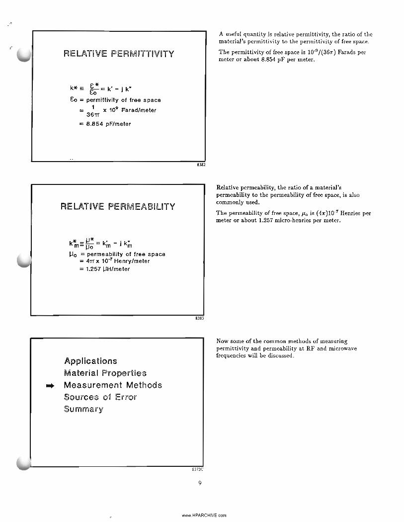
The parallel plate fixture offers a convenientcommercially available method for making permittivitymeasurements from a few hertz up to 15 MHz. Althoughcommercial solutions are not readily available above15 MHz, by combining a parallel plate fixture with aresonator, measurements can be made up to severalhundred MHz. (Von Hipple, p. 59)
The math associated with this method is relativelysimple and straight forward.
The Hewlett-Packard model HP16451B test fixture andthe model HP4194A LCR meter provide an excellentcommercially available solution for these meas~rements.
8390
However, there are some disadvantages to the parallelplate method:
• Frequency is limited to about 15 MHz, since at higherfrequencies the edge effects become difficult to deal withand equipment to make precise measurements is notcommercially available.
• This method only measures permittivity.
• Depending upon the raw state of the material, it mayhave to be prepared into sheets to be measured, makingthis method a destructive one.
8391
12
www.HPARCHIVE.com

REFLECTED WAVE METHOD
The rejleJ:ted wave method offers a means of measuringboth the permittivity and permeability of a material atfrequencies higher than is convenient with the parallelplate fixture. The material is put into a transmissionline and the impedance of the air-to-material interfaceis measured. For a finite sample length, the complexreflection coefficient of the material is first measuredwith the sample terminated with an open circuitand then with a short circuit. From these twoindependent measurements, the complex permittivityand permeability is calculated. (Von Hipple, p. 67)
The sample holder can be a coaxial transmission lineor waveguide. The open circuit can be replaced by ashort circuit offset by one quarter wavelength. If thesample is known to have a permeability of one, only onemeasurement with the sample terminated in a short'isnecessary, thus simplifying the fixture.
where
s" measurement of the material In an openand shorted transmission line
Shorted Une
~.:%. IsH" Zstanhlad~
IR d
Zcw" Zse0thlSd
Refefenoe plane
-E-H
8392
REFLECTED WAVE METHOD
Advantages-- One port measurement-- Simple fixtures
• Waveguide or coax• Easy fixtures for liquid
-- Good for high frequencies where a longelectrical length is easy to handle
-- Relatively simple math for single frequency
l'the reflected wave method only requires a oneport measurement and the fixtures are relativelysimple. Liquids can be accommodated by making thetransmission line vertical so that the sample liquid canbe poured into it.
This method is also especially good for high frequencieswhere a long electrical length is easy to handle.
The calculations for determining the material propertiesfrom the reflection measurements are relatively straightforward for single frequency measurements.
8393
REFLECTED WAVE METHOD
Disadvantages-- Destructive-- Not good for low frequencies where
electrical length becomes too long-- Complex math for multiple frequencies
'However, the reflected wave method is destructive forsolid samples and the sample must fit the transmissionline fixture precisely.
The length of the sample should be more than about 20°(electrical), so measurements at low frequencies requirelong samples for low permittivity material. For example20° at 50 MHz for a permittivity of 2 is about 24 em.
The method can be used over a broad frequency rangewith one setting of an offset short, but the mathbecomes more difficult. At frequencies where the short'soffset is near 1/2 wavelength the accuracy is degradedbecause a half wave offset short looks like a flush shortand there are no longer two independent measurements.
- 8394
13
www.HPARCHIVE.com

~1 and 5 21 of a sample in a transmissionline are measured
S-PARAMETER METHOD
PO(~tl====~;;;~~~===P=ort2
The S-parameter method is similar to the reflectionmethod but instead of measuring the sample's reflectiol'coefficient with two different terminations, its reflectioncoefficient and transmission coefficient (S11 and Szt} armeasured.
Best accuracy is obtained when the sample is 1/4wavelength long at the frequency of interest, but themethod works well over a very broad frequency range.
Oetector-V;-
air
V 3 • J 3
_____zo
air
VJn~
Source-Sample
8395
From the measured reflection coefficient of a finitesample of known length, the reflection coefficient of aninfinite sample is calculated and from this plus thetransmission coefficient, both the permittivity andpermeability are calculated. (HP Product Note 8510-3)
[2]
S-PARAMETER METHOD
Snk.!) =(1 - T2
) r lW _ (1 - r2) T
1 - rr2 Sr, - 1 _ T2r2 [1]
where r I. the reflection coefficient between Zo and Zswhen the length of materials Is Infinite ( \ =00); and
r= Zs - Zo ~ -1Zs+ Zo . ror- +1Vtr
The term T Is the transmission coefficient In the materials(of finite length) and can be written:
T = exp (-J" y'ij7t"Cf) = exp [-J(col/c) VlJr-tr- d] [3]
8396
14
www.HPARCHIVE.com

,"
c
S-PARAMIETER METHOD
Advantages-- Broad frequency range-- Well suited to microwave measurements-- Math is straightforward-- Gives e and JJ-- Can use waveguide as a sample holder
8397
S-PARAMETER METHOD
Disadvantages-- Not useful for low loss materials-- Low frequency limited by length of material-- Destructive
8398
CAVITY RESONATOR METHOD
Q Material sample fills a significant portionof cavity volume
• Exact theories applied to caviiies for verylow loss materials
The S-parameter method is well suited to microwavemeasurements and is useful over a broad frequencyrange. The math is relatively straight forward althoughthere is a possible ambiguity in taking the logarithm ofa complex number if the electrical length of the sampleis not known to within a half wavelength. (HP ProductNote 8510-3)
This method gives both permittivity and permeabilityand a convenient sample holder can be nothing morethan a quarter wave piece of waveguide. The TRLcalibration feature of the HP8510B microwave networkanalyzer allows the network analyzer to be calibratedusing the empty sample holder and a flat short.
The S-parameter method does not give accurate valuesof loss tangent for low loss materials (tan 6 < 0.1)although it does give good results for the real part of thepermittivity.
The low frequency limit is governed by the practicallength of the material sample. Like the reflected wavemethod, the length of the sample should be about 10° to20° (electrical).
Because the sample must fit the transmission line veryprecisely, sample preparation requires close tolerancesand is "destructive to the material.
Low loss tangents can be accurately measured by severalmethods based upon resonant structures. At microwavefrequencies, the resonant cavity is often used where thematerial under test fills a significant portion of the cavityvolume. Exact theories are applied to the analysis of theresonant frequency and Q of the cavity to determine thecomplex permittivity of the material. (Afsar, 1986)
However, because only two quantities (resonantfrequency and Q) are measured there is not enoughinformation to calculate the permeability.
c'--- ~8399
15
www.HPARCHIVE.com

..
TE01n CAVITV
Very precise permittivity measurements can be madewith a well constructed cylindrical cavity operatingin the TEoln mode. In this case the sample is in theform of a disc with the same diameter as the cavity andideally an integral number of 1/2 wavelengths thick.(Afsar, 1986)
These cavities are usually constructed of helicalwaveguide to prevent the degenerate TMll mode. TheNational Institute of Science and Technology (NIST) hasobtained very low uncertainties with this type of cavity.(Vanzura)
legging or temperature control
Small coupling aperturea(to waveguide)
Helleal wavegude
Electric field
Dielectric disc ..mple
Micrometer
I tj
I I'- ---• ..,,,.nt ...et.....cy
.termlned" E-length ,...:.::..:.:..I .........
101' tuning - I-- ..----1 -
.- "-
j I---
RIrdby
Platon
8400
PARALLEL PLATE DIELECTRICRESpNATOR
The parallel plate dielectric resonator is convenient formaking measurements on low loss materials. The modesof this resonator have been described by Kobayashi(Kobayashi, 1980) and the TEoll mode is the mostuseful for making measurements. (Kobayashi, 1985)
Parallel
conducting "-~IlIIlIIIlIIJ~~IIlIlIIIII.""plates
-- E field........... H field
Electric field strength
Dielectric cylindar
8401
OPEN CAVnV DllElECTR~C
RESONATORTE01S Mode
-- E field--- H field
8 is the fraction of the total energythat Is contained in the dielectric
The open cavity dielectric resonator operating in theTE01 6 mode is another method for making precisemeasurements of the complex permittivity of lowloss materials. In this mode, 6 is the fraction of theresonator's total energy that is contained within thedielectric material. (Nishikawa, 1987)
The complex permittivity is calculated from the resonantfrequency and Q of the resonator with the materialsample installed. The resonant frequency and Q aremeasured by a microwave network analyzer.
It is important to note that due to the extremely highQ's required to make accurate measurements of low lossmaterials, the network analyzer must have frequencyresolution of a few Hertz. The HP8510B and theHP8720B are the only commercially available microwavenetwork analyzers that meet this requirement.
8402
16
www.HPARCHIVE.com

."'
OPJlEN C~V~TV D~ElECTR~C
RESON~TOR METHOD
-- Dieleciric and! me~al walll surh\ce are nonin contad (small error in tan S)
-- Method! is suitable for a broad rangeog frequencies with the appropriate cavinies
8403
In the open cavity dielectric resonator, the materialunder test does not contact the metal surface of thefixture (in this case the resonator) and thus there iue noerrors due to undesired gaps or poor metalization. Themethod is narrow band because of the resonant cavity,but it is suited for a wide range of frequencies with theappropriate cavities.
MUR~T~ DRGSER~[ES
F~XTLDR!ES
R404
l\ series of cavities along with software to calculatecomplex permittivit.v from their measured resonantfrequency and Q is a\'ailable from Murata ManufacturingCo., Ltd. These fixtures cover the frequency range of1.5 GHz to 18 GHz and provide a con\'enient way toaccurately measure complex permitti\'ity at microwavefrequencies. (Reference 8)
MUR~1"~ DRG g553M!E~SUR!EM[ENl F~X1"LDRfE
Silver plating Material Sample
The actual cavity is made from silver-plated ceramicin order to control the ca\'ity's temperature coefficient.The material sample is machined to a specified sizeand shape and mounted on a dielectric support. Thewhole assembly is enclosed in an outer metal case forprotection. (Nishikawa. 1987)
AFcon~
SupportSilver plated
ceramic cavity
17
www.HPARCHIVE.com

MURATA DRG SERIES FIXTURES
Frequency range: 1.5 to 18GHz&r range: 10 to 100Tan S range: 10'" to 10-3
Tan S resolution: 1 x 10'"
8406
MURATA ORESV' 3 SOFTWARE
-- Calculation of complex permittivity in TEo16 modedielectric resonator by the variational me~hoCl1
-- Convenient way to calculate permittivity frommeasurements in the DRG 8553 fixture
-- Written in HP Basic, it runs on a desktop computer
8407
CAViTY RESOlMATOR METHOD
Advantages-- Good for very low loss material-- Capable of very high accuracy
8408
18
This series of cavities is capable of measuring relativepermittivities from 10 to 100 and loss tangents down toabout 10 micro-radians with one micro-radian resolution
Murata also offers software to conveniently perform thecalculation of complex permittivity from the measuredresonant frequency and Q of the cavity with the sampleinstalled.
The cavity resonator method is good for measuring verylow loss materials and is capable of very high accuracy.
www.HPARCHIVE.com

II,I
CAVITY RESONATOR METHOD
Disadvantages-- Complex math-- Destructive-- Single frequency for fixed dimension cavity
CAVITY PERTURBATION METHOD
• Material placed so .. to disturb fields In acavity resonator
• Measure change In resonant frequency and Q
- Sample size small enough not tochange field distribution
- Electric field must be uniformacross sample
.",
CAVITY PERTURBATION METHOD
8410
However it does involve rather complex math, and sincethe material sample must be machined to a certain sizeand shape it is a destructive test. Also, it is a singlefrequency measurement for anyone sized fixture.
The romty perturbation method for measuring complexpermittivity is similar to the cavity resonator methods,but in this case a small sample of the material to bemeasured is placed in a resonator so as to disturb theelectric field. The sample must be small enough that itdoesn't change the field distribution and the field mustbe uniform across the sample. (Von Hipple, p.71; Afsar,1986; Bussey)
The sample is usually in the form of a thin rod in aTMo1o mode cavity. A thin tubular holder in a TMo10mode cavity is a convenient way to measure liquids.(Afsar, 1986)
TE Oll TM010
Sample
e' = 1 + 0.539 (g 1 - f 2 ) Vf1 ;;:
e" = 0.269 fll.-- 1.- ~ V\02 01P ~
- - - - - - E field--Hfield
8411
19
The equations shown here are approximate for thinsamples. The exact equations involve Bessel functions ofthe first and second kinds. (Von Hipple, p. 122)
www.HPARCHIVE.com
CAVITY PERTURBATION METHOD
Advantages-- Simple, convenient, reasonably accurate-- Good for low 8' and moderate losses-- Simple fixture for measuring liquids
CAVITY PERTURBATIO~ METHOD
Disadvantages-- Practical difficulties and math approximations
can lead to 10% uncertainties for C'
-- Usually destructive-- Single frequency
SUBSTRATE MIEASUREME~T
o Use TE o11 modes to probe materialct Non contact measurement preferrableo Non destructive is desirable
8412
8413
8414
20
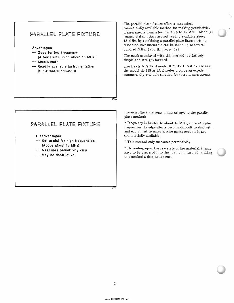
The cavity perturbation method is simple, convenient,and reasonably accurate. In addition it is good for lowvalues of permittivity and moderate losses and is aconvenient way to measure liquids.
However, practical difficulties and math approximationscan result in uncertainties of up to 10% of the measuredpermittivity. (Afsar, 1986)
In addition, the sample usually has to be machined to aprecise size, making the measurement a destructive one.It is also a single-frequency measurement.
A variation on the perturbation method has been usedto measure fiat sheets such as substrate material. A pairof TEou mode dielectric resonators are used to probethe material. The TEoll mode is chosen to minimize theeffects of leakage out of the fixture in the plane of thesample. Because there is no contact between the sampleand the fixture in this method, errors due to undesiredgaps between the two are eliminated. (Nishikawa, 1988)
www.HPARCHIVE.com

j•
"t'
SUBSTRATE F~XTURE
Support Metal cavity
~/IEsbI""7~Specimen
Dielectric Resonator
Cross Section of Measuring Instrument
8415
ELECTRIC FIELD DISTFUBUTION
_'I:'m~u:J'8t ~~- :. ~o_
, .
t\Z\!TI-II 0 lllmml
8416
Two dielectric resonators, support TEOlC modes. Thedielectric resonators trap the electromagnetic energyin the cavity made of two separate metal pieces. Theresonant frequency is perturbed by inserting the materialsample between the two metal pieces which form thecavity, and the complex permittivity is calculated fromthe measurement of the perturbation of the resonantfrequency and Q. (Nishikawa, 1988)
The electric field distribution of the TEo1C5 mode inthe fixture is shown in the figure. The trapped energylocalizes the permittivity measurement in the plane ofthe sample. Since the magnitude of field strength isrelatively constant midway between both resonators,the amount of perturbation by the sample is notchanged by changing the sample's position along thez-axis. Therefore a precise measurement independentof the sample's position along the z-axis can be made.(Nishikawa, 1988)
PERMITTIVITY
£r = t:.c.l r Ie ro - 1\ + 1t:.c.lr0 \ "I
where: £r =relative permiUivlty of test substrate
ero = relative permittivity of referencesubstrate
t:.c.lr = change In frequency with test substratet:.r.lro = change In frequency with reference
substrate
8417
21
This method is a relative measurement, referenced to aknown standard substrate. The equations to determinethe relative permittivity and loss tangent are derivedfrom the perturbational theory of small dielectric objectsin a cavity. This is the equation for relative permittivity.(Nishikawa, 1988)
www.HPARCHIVE.com

The loss tangent of the test suostrate is found from thisequation.
The contribution of the substrate thickness is negligibll'because the test and standard substrates are of the samethickness. (Nishikawa, 1988)
t
"
ian S£; ro - 1
E:ro
where: ~an 6 = loss iangen~ of test subs~ra~e
tan 60 = loss ~angen~ o~ reference subs~ra~e
00 = Q of resona~or wi~h ~es~ subs~ra~e
0 00 = Q o~ resona~or wi~h reUerence subs~rafte
8418
MURATA [)~G ~~2(Q) SER~ES
SUBSTRATE F~XTURES
FREE S~AClE METHODS
o Microwave energy is dlirecQed on~o ihe s81mple
wi~h an~ennas
" Similar to S-lParameter me~hodl
" Can also use qjuasi-opQic3l1 resonators
8419
A fixture for making these types of substratemeasurements is available from Murata ManufacturingCompany, Ltd. Fixtures are available for three differentfrequencies and two different substrate thicknesses.(Reference 8)
Another non-destructive method that makes bothpermittivity and permeability measurements is thefree-space method. This approach does no! require a testfixture.
Quasi-optical resonators can also be used to makematerial measurements in free space, and are especiallyuseful at millimeter-wave frequencies and above.
www.HPARCHIVE.com

r--
FREE SPACE METHODSTo Network Analyzer
Port 1 Port 2
Measuring reflection and transmission of the sample
8421
FREE SPACE METHODSInput JtOutput
~\ /\ /\ /\ I\ I\ f s
/ll/llluJl/lrff~/I;nmmlliill/lHemispherical type of open resonator formillimeter-wave measurments.
8422
FREE SPACE METHODS
Advantages-- Non destructive-- Contactless-- Broadband
-- Measures ~* and £*-- No errors due to machining
tolerances of sample
8423
23
In the free-space method, microwave energy is directedonto the material sample with narrow beam antennas.This is similar to the S-parameter method in thatthe waves reflected from the material and transmittedthrough it are measured. The same equations are usedto find the surface impedance and propagation constantof the material, and to solve for permittivity andpermeability. It is important to focus the microwaveenergy onto the center of the sample in order to avoiderrors due to edge diffraction. (Ghodgaonkar)
This is one example of using a quasi-optical openresonator of the hemispherical type. The confocalFabry-Perot open resonator can also be used. Thesample is placed in a position where the electromagneticfields are focused, and the analysis is similar to thecavity resonator. Extremely high Q's can be obtainedwith these resonators, allowing measurements of losstangents as low as micro-radians. Accuracies rangingfrom 0.2 to 1 percent for the real part of permittivityand 2 to 10 percent for tan chave been reported. (Afsar,1984)
Free-space methods are inherently non-destructive andthe cross sectional shape of the sample is not importantas long as it has fiat parallel faces. Therefore, there areno errors due to machining tolerances of the sample.
Because the sample is not contacted by a fixture,it is a good method for making high temperaturemeasurements. Antennas can be placed outside thetemperature chamber and shined in through microwavewindows. (Ghodgaonkar)
It is a broadband method and is capable of measuringboth permittivity and permeability.
Free-space methods are especially good for measuringabsorptive materials in the manner in which they will beused.
www.HPARCHIVE.com

FREE SPACE METHODS
Disadvantages-- Requires large sample size- Must be careful to avoid errors due
edge diffraction
ApplicationsMaterial PropertiesMeasurement Methods
.. Sources of ErrorSummary
SOURCES OF ERROR
G Network analyzer errorse Fixture errorso Sample errorsG Approximations in theory
However, the free-space methods require large samplesizes in comparison to a wavelength, and care must betaken to avoid edge diffraction.
Like the S-parameter method, the free-space methodusing antennas to illuminate the sample does not giveaccurate values of loss tangent for low loss materials.
The open resonator methods, however, do give quitegood results for measuring low loss materials-but theymeasure only permittivity.
8424
This section discusses several sources of error inmeasuring the electrical properties of materials.
8372D
The major sources of error in making materialmeasurements are:
'" instrumentation errors due to network analyzer;
'" errors in the construction and application of thefixtures;
'" errors in preparing the sample; and
'" errors that may be due to approximations in thetheory behind the measurement method used.
8425
24
www.HPARCHIVE.com
;,

o
NETWORK ANALYZER ERRORS
-- Directivity-- Port matches-- Frequency response-- Frequency accuracy
FIXTURE ERRORS
-- Fringing capacitance-- Lead parasitics-- Finite a-- Fixture reflections-- Improper sample placement
SAMPLIE ERRORS
-- Manufacturing tolerances-- Edge diffraction-- IJ not equal to 1 when required
8426
8427
25
There are many error sources associated with makinga measurement with a modern network analyzer andthey have been discussed at length elsewhere. (RyttingjDonecker; Fitzpatrick)
Directivity errors will affect the reflection coefficientmeasurement for samples that have low reflectioncoefficients (those that are lossey and have lowpermittivity). Samples with high reflection coefficients(those with low loss and high permittivity) will beadversely affected by port match errors. Frequencyresponse errors affect the measurement of the reflectionand transmission coefficients as they vary with frequency.And frequency accuracy is important in measuring theresonant frequency of cavity fixtures.
Fixture errors can be due to fringing capacitance or leadparasitics in the parallel plate type of fixture, or finiteQ in the cavity fixtures. Reflections from the fixtureitself rather than the sample will also contribute toerrors. Proper placement of the sample in the fixture isimportant to making good measurements.
Errors in sample preparation will affect themeasurements of the material's properties. Samples thatare in contact with the measuring fixture must fit snugly(especially in the direction of the electromagnetic fieldsused to probe the sample).
Where the size of the sample enters into the calculations,it must be known as accurately as possible. Usuallyit is best to machine the sample to as close toleranceas possible and then precisely measure its actualdimensions.
Edge diffraction in the free-space methods yieldssignificant errors and can make the measurement uselessif not addressed.
A sample with a relative permeability not equal to 1.00will yield errors in methods that are meant to onlymeasure permittivity.
www.HPARCHIVE.com

THEORY APPROXIMATIONS
-- Approximate solutions of cavity equations-- Ambiguities in phase for S-parameter solution-- Use of inappropriate method for the material
ApplicationsMaterial PropertiesMeasurement MethodsSources of Error
... Summary
8429
8372E
26
Some of the methods described in the last section (suchas the perturbation and cavity methods) have practicsolutions that are based on approximations. The moreexact the theoretical solution is, the more accurate th(~
measurement results will be.
Methods based on measuring the propagation constantthrough the material (the S-parameter and free-spacemethods, for example) are susceptible to ambiguitiesin phase. If the measured phase is off by an integralmultiple of 3600 (electrical), the calculated permittivityand permeability give results that are physicallyimpossible.
Finally, it is important to use the appropriate methodfor the material being measured. For example, theS-parameter method would not be used to measure theloss tangent of a low loss material.
There are many different ways to measure the electricalproperties of materials and only a few of the mostcommon ones have been discussed here. Other methodsexist for making measurements at sub-hertz frequencies(Von Hipple, p. 52) and at millimeter-wave and opticalfrequencies (Afsar, 1984). In addition there are methodsthat are optimized for permeability measurements (VonHipple, p. 125) and measurements on superconductors(Fiedziuszko; Fathy).
www.HPARCHIVE.com

Reference
1. A. R. Von Hipple, Dielectric Materials andApplications. New York: MIT Technology Press andWiley, 1954. (Note: This is probably the single mostuseful reference in material measurements and isconsidered by many to be the bible of the field.)
2. M. N. Afsar, "The measurement of the properties ofmaterials," Proceedings of the IEEE, vol. 74, no. 1, pp.183-199, Jan. 1986. (Extensive references)
3. Hewlett-Packard Company, "Measuring dielectricconstant with the HP8510 network analyzer," Productnote 8510-3, August 1985.
4. E. J. Vanzura, "Advances in NIST dielectricmeasurement capability using a mode-filtered cylindricalcavity," 1989 IEEE MTT-S International MicrowaveSymposium Digest, pp. 901-904, June 1989.
5. Y. Kobayashi and S. Tanaka, "Resonant modes of adielectric rod resonator short-circuited at both ends byparallel conducting plates," IEEE Trans. MicrowaveTheory and Tech., vol. MTT-28, no. 10, pp. 1077-1085,Oct. 1980.
6. Y. Kobayashi and M. Katoh, "Microwavemeasurement of dielectric properties of low-loss materialsby the dielectric rod resonator method," IEEE Trans.Microwave Theory and Tech., vol. MTT-33, no. 7, pp.586·592, Jul. 1985.
7. T. Nishikawa, et. al., "Precise measurement methodfor temperature coefficient of dielectric resonatormaterial," 1987 IEEE MTT-S International MicrowaveSymposium Digest, pp. 277-280, June 1987.
8. Murata Manufacturing Company, Ltd. InternationalDivision, 3-26-11 Nishi-rokugo, Ohta-ku, Tokyo 144,Japan.
9. H. E. Bussey, "Measurements of RF properties ofmaterials- a survey," Proceedings of the IEEE, vol. 55,no. 6. pp. 1046-1053, June 1967. (Extensive references)
10. T. Nishikawa, et. al., "Precise measurementmethod for complex permittivity of microwave dielectricsubstrate," Conference of Precise ElectromagneticMeasurements, Tsukuba, Japan, June, 1988.
11. Deepak K. Ghodgaonkar, V. V. Varadan, and V.K. Varadan, "A free-space method for measurementof dielectric constants and loss tangents at microwavefrequencies," IEEE Transactions on Instrumentationsand Measurement, vol. 37, no. 3, pp. 789-793, June1989.
12. M. N. Afsar, "Dielectric measurements ofmillimeter-wave materials," IEEE Trans. MicrowaveTheory and Tech., vol. MTT·32, no. 12, pp. 1598-1609,Dec. 1984. (Extensive references)
27
13. D. Rytting, "Advances in microwave error correctiontechniques," presented at the Hewlett-Packard RF andMW Symp. 1987.
14. S. Donecker, "Determining the measurementaccuracy ofthe HP8510 microwave network analyzer,"presented at the Hewlett-Packard RF and MW Symp.1985.
15. J. Fitzpatrick, "Error models for systemsmeasurement," Microwave Journal, May 1978.
16. S. J. Fiedziuzko and P. D. Heidmann, "Dielectricresonator used as a probe for high Tc superconductormeasurements," 1989 IEEE MTT-S InternationalMicrowave Symposium Digest, pp. 555-558, June 1989.
17. A. Fathy, D. Kalokitis, E. Belohoubek, "Microwavecharacteristics and characterization of high Tcsuperconductors," Microwave Journal, October 1988, pp.75-94.
www.HPARCHIVE.com

(h~ ~i~.z:J6Copyright © Hewlett Packard Co. September, 1989
www.HPARCHIVE.com