AN135 Measurement calibration and measurement uncertainty ...

Whi
te P
aper
Calibration of Weighing Instruments Measurement Uncertainty Expert Know-how
Contents
1. Introduction 2
2. Basic concepts of calibration 3
3. Calibration of non-automatic weighing instruments (NAWI) 4
4. Calibration Procedure of EURAMET cg-18 5
4.1. Measurement Methods and Measurement Results 5
4.2. Standard Uncertainty for Discrete Values 6
4.3. Expanded Uncertainty at Calibration 9
4.4. Uncertainty of a Weighing Result 10
5. The Concept of Minimum Weight and Safe Weighing Range 12
Conclusion 15
References 16

2 White Paper METTLER TOLEDO
Whi
te P
aper
Cal
ibra
tion 1. Introduction
The metrology of measuring instruments is a critical component of any organization’s quality operations. The standout prerequisite for traceable and accurate weighing is the effective calibration of weighing instruments, covered under the company's quality management system. It seems, however, that not all organizations have a thorough understanding of current metrological science. Unless specifically addressed by metrologists, it is still a widespread belief that calibrating a weighing instrument mainly consists of placing reference masses on the weighing platform with the objective of assessing the deviation between the indication and the mass value of the reference. Not everybody is aware that calibration is a process that establishes a relation between quantity val-ues provided by measurement standards and corresponding indications, which is only complete if the contribut-ing measurement uncertainties are taken into account.
With regards to non-automatic weighing instruments, a manifold of calibration guidelines exist on a national level, which are all based on the concepts described in the Guide of the Expression of Uncertainty in Measure-ment (GUM). However, on a global level, only one document remains: The EURAMET calibration guideline cg-18 "Calibration of non-automatic weighing instruments". This document will also act as basis for the future develop-ment of a US calibration guideline.
This article focuses on the test procedures and measurement uncertainty estimation of the EURAMET cg-18 calibration guideline, specifically highlighting its practical implications for applications in the laboratory and the production area. One appendix of the guideline introduces the so-called "minimum weight", i.e. the smallest sample quantity required for a weighment to just achieve a specified relative accuracy of weighing. The minimum weight defines the lower boundary of the safe weighing range, and weighing quantities within the safe weighing range guarantees compliance with the required weighing process tolerance. In simple words, calibration and the subsequent interpretation of its data establishes minimum weight and safe weighing range, and ensures the user meets applicable quality requirements.

3White Paper METTLER TOLEDO
2. Basic concepts of calibration
Calibration is one of the key activities that must be performed periodically when instruments are used for quality relevant measurements. Internationally, there are many standards which stipulate this requirement, e.g. ISO9001, GMP regulations or standards concerned with food safety. While almost everybody working in quality control and quality assurance in the laboratory or in the production environment is familiar with the applicable require-ments stipulated in these documents, there is no common understanding on the definition, the implementation and the specific activities that comprise calibration. Let us therefore start by establishing a common platform on what calibration is.
Calibration is a set of activities carried out on a measurement instrument to understand its behavior by establish-ing a relationship between known values (measurement standards) and the associated measured values (indi-cations). The relationship consists of a deviation and its associated uncertainty. The "International Vocabulary of Metrology" (VIM)1 provides the official definition of calibration:
"Operation that, under specified conditions, in a first step, establishes a relation between the quantity val-ues with measurement uncertainties provided by measurement standards and corresponding indications with associated measurement uncertainties and, in a second step, uses this information to establish a rela-tion for obtaining a measurement result from an indication."
It is evident that the relation between the known and the measured values can only be established if the associ-ated measurement uncertainties are derived. Unfortunately, in practice there is a widespread misconception in regards to calibration as most users do not consider measurement uncertainty when "calibrating" an instrument. Measurement uncertainty is defined in the "Guide to the Expression of Uncertainty in Measurement" (GUM)2:
"Parameter, associated with the result of a measurement that characterizes the dispersion of the values that could reasonably be attributed to the measurand."
Basically, measurement uncertainty describes how far away from the true value a measurement result reason-ably might be. The measurement results and the estimated uncertainty are usually documented in so-called calibration certificates. ISO/IEC 170253 specifies the general requirements for the competence of laboratories to carry out tests and/or calibrations. An accreditation by an accreditation body is the formal process that certifies that a calibration laboratory is competent and fulfils the requirements stipulated by ISO/IEC 17025.
Before detailing how weighing instruments can be calibrated and their respective measurement uncertainty es-timated, we would like to emphasize another misconception in regards to calibration: Besides calibration, an instrument can also be adjusted. Adjustment is defined in the "International Vocabulary of Metrology" (VIM) as follows:
"Set of operations carried out on a measuring system so that it provides prescribed indications correspond-ing to given values of a quantity to be measured."
In other words, when adjusting an instrument, its indications are modified in a way so that they correspond – as far as possible – to the quantity values of the measurement standards applied. Unfortunately, many users apply the words calibration and adjustment interchangeably, incorrectly or even randomly. Quite often, they talk about calibrating a weighing instrument, however they mean adjusting it. The VIM also emphasizes this by stating:
"Adjustment of a measuring system should not be confused with calibration, which is a prerequisite for ad-justment. After an adjustment of a measuring system, the measuring system must usually be recalibrated."
This statement highlights another important aspect of calibration: Before an instrument is adjusted, it must be first calibrated in order to understand – and document – its behavior. This is specifically important in order not to break the traceability chain of preceding measurements on the device. Equally after an adjustment, the instru-

4 White Paper METTLER TOLEDO
Whi
te P
aper
Cal
ibra
tion ment must usually be recalibrated. Quite often, users talk about an "as found" calibration, i.e. a calibration of the
instrument before any modification (adjustment) is carried out, and about an "as left" calibration, i.e. a calibra-tion of the instrument after any necessary adjustment and/or repair has been carried out.
Besides calibration, measuring instruments can also be verified. Usually, instruments need to fulfil predefined requirements, quite frequently expressed as tolerances. The "International Vocabulary of Metrology" (VIM) defines verification as follows:
"Provision of objective evidence that a given item fulfils specified requirements."
While calibration only establishes the relationship between measurement standards and indications ("how well the instrument performs"), verification assesses the instrument on whether or not it meets specific requirements ("does the instrument perform well enough"). Usually, the outcome of verification is a "pass" or a "fail", while calibration itself does not provide an assessment. However, the calibration procedure is in many cases the start-ing point for a subsequent assessment of the results. Therefore, it is common practice to document the assess-ment as an annex to the calibration certificate. Tolerances can come from a variety of sources. With respect to weighing instruments, aside from the manufacturer who specifies tolerances for each balance or scale model, international or national testing recommendations and handbooks for weighing instruments used for applica-tions involving commercial transactions (like OIML R76-14 or HB445) as well as industry specific regulations (like USP General Chapter 416) also specify tolerances. However, even more importantly, the user also needs to specify weighing tolerances that assure that the instrument performs well enough to fulfil his specific process re-quirements. In view of the application of the weighing instruments, these tolerances are the most important ones as they have a direct impact on the quality of the final product.
3. Calibration of non-automatic weighing instruments (NAWI)
Non-automatic weighing instruments have become ubiquitous for applications in the laboratory, on the produc-tion floor and in many other business areas (retail, pre-packaging, vehicle weighing, etc.). Due to their impor-tance, calibration guidelines have been developed by many different organizations, especially since electronic weighing instruments were established on the market. Traditionally, these calibration guidelines were applied on a national level as the underlying issuing organizations were either national metrology institutes, national ac-creditation bodies or other nationally recognized organizations.
As a consequence of an effort to harmonize the requirements for the calibration of NAWIs on an international level, the guideline EURAMET cg-18 "Guidelines on the calibration of non-automatic weighing instruments" was developed by the leading European metrology institutes. It is now widely applied by calibration laboratories in Europe, and many national accreditation bodies take it as the state-of-the-art reference for accreditation of cali-bration laboratories7. The guide has been adopted by SIM (Sistema Interamericano de Metrología)8 and thus is formally recognized by the regional American metrology organizations. Furthermore, it is also applied by several calibration laboratories in Africa and Asia, however not yet systematically.
Due to its widespread use, the EURAMET cg-18 calibration guide is the most frequently used reference document for the calibration of NAWIs. There are recent activities in the US, triggered by ASTM, who are interested in taking over the methodology of cg-18 and transposing it into an ASTM standard, which could potentially serve as a fu-ture national calibration guide for the US.

5White Paper METTLER TOLEDO
4. Calibration Procedure of EURAMET cg-18
4.1 Measurement Methods and Measurement Results
Usually, a repeatability test, a test for errors of indication and an eccentricity test are performed to assess the performance of the weighing instrument. With respect to assessing the normal use of the instrument or evaluat-ing the performance under special conditions of use, EURAMET cg-18 allows for a flexible execution of the tests; however adherence to specific minimum requirements of the tests is stipulated as explained in the following paragraphs.
4.1.1 Repeatability test
Usually, a test load of about 0.5 · Max to Max is quite common (Max stands for the maximum capacity of the instrument). However, this is often reduced for instruments where the test load would amount to several 1000 kg. For multiple range and multi-interval instruments, a load below and close to the capacity of the range/inter-val with the smallest scale interval d may be sufficient. A special value for the test load may be agreed where this is justified in view of a specific application of the instrument. An example would be weighing standards or samples on analytical and micro balances where the typical quantity that is weighed is at the low end of the measurement range. Here, a small repeatability test load at the lower end of the weighing range may be agreed. The test load should, as far as possible, consist of one single body. A strict requirement is that the load has to be applied at least 5 times, and at least 3 times where the load is or exceeds 100 kg.
Repeatability is quantified by calculating the standard deviation of the repeated measurements:
with n being the number of repeated weighings, Ii representing the individual indications and Ī being the mean value of the indications.
4.1.2. Test for errors of indication
This test requires at least five test points, distributed fairly evenly over the weighing range of the instrument. Note that zero is considered to be a test point. The reason is that a measurement uncertainty can also be allocated to zero. Consequently, an error of indication test with four physical test loads, plus the zero, fulfils the minimum requirements of EURAMET cg-18. The individual errors of indications Ej are calculated as:
Ej = Ij - mref,j
Usually, the reference value of mass mref,j of the test loads is approximated to its nominal value mN,j or its con-ventional value mc,j . Ij represents the individual indications of the error of indication test points.
4.1.3. Eccentricity test
The test is carried out with a test load of about Max/3 or higher. Depending on the shape of the load receptor, the number of test points might vary. For rectangular and round platforms, usually four positions and the center are taken as test points. From the indications Ii obtained in the different positions, the differences ΔIecc,i are usu-ally calculated as:
ΔIecc,i= Ii- I1

6 White Paper METTLER TOLEDO
Whi
te P
aper
Cal
ibra
tion with Ii representing the indications at the different positions of the load outside the center, and I1 normally being
the center reading (if the load can be placed in the center of the platform). For estimation of the uncertainty the largest ΔIecc,i (as absolute value) will be taken into account, which will be abbreviated |Δecc,i|max.
4.2 Standard Uncertainty for Discrete Values
The first step with regards to estimating the measurement uncertainty is deriving the so-called standard uncer-tainty for discrete values. The basic formula for that step is:
E = I - mref
with the related variance:
u2(E) = u2(I) + u2 (mref)
For better legibility, the index j was omitted. Note that above formulas apply for every error of indication test point, including zero. This means that for every error of indication test point the associated standard uncertainty is de-rived individually. This is graphically indicated in figure 1.
As can be seen from the above equation, the standard uncertainty for discrete values comprises of two main sources: u(I), the standard uncertainty of the indication and u(mref), the standard uncertainty of the reference mass. This is also evident from the definition of calibration as per the VIM, which states that the quantity values provided by measurement standards as well as the corresponding indications are associated with measurement uncertain-ties.
4.2.1. Standard Uncertainty of the Indication
The standard uncertainty of the indication comprises of four individual contributions, which account for the round-ing error of the no-load indication, the rounding error of the indication at load, the repeatability and the eccentricity of the weighing instrument. Note that the rounding error is taken into account twice as any indication I related to a
Figure 1: Graphical indication of the error of indication test points with their respective standard uncertainties from a calibration certificate (green circles for as found, before adjustment, and blue rhombi for as left, after adjustment of the scale).
600
500
300
400
200
100
-100
-3000 50 100 150 200 250 300
-200
Erro
r of I
ndic
atio
n [g
]
Calibration Points [kg]
As Left
As Found
0

7White Paper METTLER TOLEDO
test load is the difference of the indications IL at load and I0 at no-load. The standard uncertainty of the indication is obtained by the following formula:
a. Rounding error of the no-load indication and the indication at load
The variances of the rounding errors have been derived based on the assumption of a rectangular distribution of the unrounded (analogue) measurement valuesi. In other words, it was assumed that the probability of oc-currence of any unrounded measurement value (which is not indicated on the instrument) is constant within the limits of or , respectively. The standard deviation of a rectangular distribution is:
leading to the variances indicated above in the formula. In case that the scale interval at no-load and at load is the same (abbreviated with d), the total uncertainty accounting for the rounding error of the indication would thus be derived as:
This value is also known from other regulations (e.g. USP General Chapter 41) and constitutes the lowest stan-dard uncertainty of the indication that can be realized on a weighing instrument for the case that the standard deviation of the repeatability is zero and the uncertainty related to eccentricity is neglected.
b. Repeatability
Normally, a single repeatability test is carried out during calibration. When estimating measurement uncertainty, the standard deviation s is considered as being representative for all indications of the instrument, and is taken as the uncertainty contribution of repeatability. In case that more than one repeatability test is carried out, EUR-AMET cg-18 describes specific rules how to apply the standard deviations within the weighing range(s) of the instrument.
c. Eccentricity
The standard uncertainty accounting for eccentricity urel(δIecc)I is approximated as a linear function of the indi-cation I. The proportionality factor, the relative uncertainty urel(δIecc) is given by:
with Lecc being the test load applied.
4.2.2. Standard Uncertainty of the Reference Mass
The standard uncertainty of the reference mass usually comprises of four individual contributions, which account for the tolerance or the uncertainty of the reference mass, air buoyancy, a possible drift of the reference mass since its last calibration and convection effects due to potential temperature differences between the reference mass and the instrument.
u2(mref ) = u2 (δmc ) + u2(δmB ) + u2(δmD ) + u2(δmconv)
i) A rectangular distribution is assumed for most of the contributions to measurement uncertainty. As the rectangular distribution is explained for the case of rounding, it will not be detailed individually anymore in the following chapters.

8 White Paper METTLER TOLEDO
Whi
te P
aper
Cal
ibra
tion
ii) Recourse is taken to section 10 of OIML R111-1: The density of the material for weights shall be such that a deviation of 10% from the specified air density (1.2 kg/m3) does not produce an error exceeding one quarter of the maximum permissible error.
a. Tolerance / uncertainty of the reference mass
Whether the tolerance or the uncertainty of the reference mass is taken as a contribution to the above formula depends on whether the nominal or the conventional value is taken as reference mass for the calculation of the individual errors of indication. If the nominal value mN is used, then the weight tolerance Tol is taken into ac-count, leading to:
Note that OIML R111-19 and ASTM E61710 use the term "maximum permissible error" for the tolerance, for which quite frequently the abbreviation mpe is used.
If the conventional value mc is applied, then the uncertainty U and the respective coverage factor k of the weight calibration certificate is taken into account, leading to:
It is evident that the contribution of u(δmc) can be minimized if the conventional value mc instead of the nominal value mN is applied. Where a test load consists of more than one standard weight, the standard uncertainties are added arithmetically not by sum of squares, to account for assumed correlations of the weights.
b. Buoyancy
In general, air buoyancy can be corrected if the density ρ of the reference mass and the air density ρa at the time of calibration of the weighing instrument are known. Normally, however, the air density is not measured during calibra-tion of the weighing instrument, so that an air buoyancy correction is not carried out frequently in practice. In these cases, the (unknown) buoyancy correction is taken into account as an intrinsic part of the buoyancy uncertainty.
For this scenario, two cases have to be distinguished, one with the instrument being adjusted immediately before calibration, and the other with the instrument not being adjusted before calibration. If the instrument is adjusted imme-diately before calibration, the respective buoyancy uncertainty is minimized as a potential change in buoyancy due to different air densities at calibration and adjustment is removed. If the instrument is adjusted independent of the calibra-tion, worst-case assumptions should be made in regards to the potential air density variation between adjustment and calibration. If conformity of the standard weights with OIML R111-1 is established, the following worst-case uncertain-ties can be derivedii:
If the instrument is adjusted immediately before calibration:
If the instrument is not adjusted before calibration (thereby assuming an air density variation of 10% of the refer-ence density of air ρ0 between adjustment and calibration):
Especially the last formula constitutes a very conservative approach to estimating uncertainty due to buoyancy, and if there is evidence that air density variations are smaller than 0.1 ρ0 this value should be substituted by a less conser-vative value.
9White Paper METTLER TOLEDO
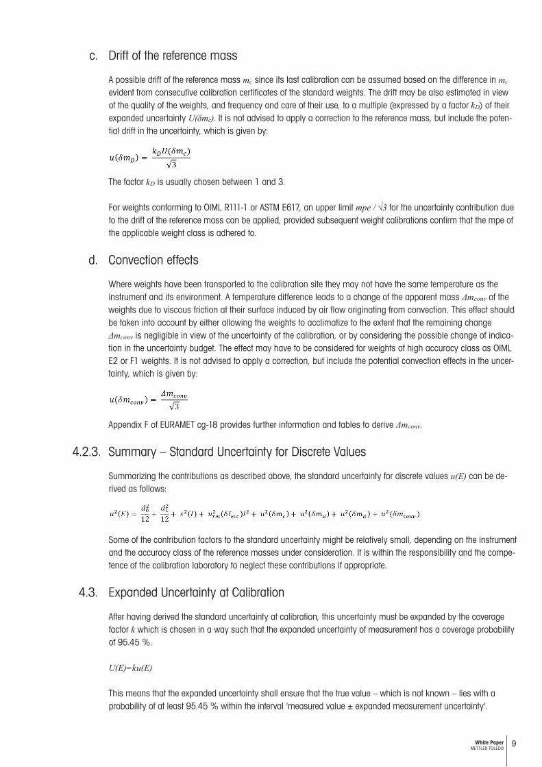
c. Drift of the reference mass
A possible drift of the reference mass mc since its last calibration can be assumed based on the difference in mc
evident from consecutive calibration certificates of the standard weights. The drift may be also estimated in view of the quality of the weights, and frequency and care of their use, to a multiple (expressed by a factor kD) of their expanded uncertainty U(δmc). It is not advised to apply a correction to the reference mass, but include the poten-tial drift in the uncertainty, which is given by:
The factor kD is usually chosen between 1 and 3.
For weights conforming to OIML R111-1 or ASTM E617, an upper limit mpe / √3 for the uncertainty contribution due to the drift of the reference mass can be applied, provided subsequent weight calibrations confirm that the mpe of the applicable weight class is adhered to.
d. Convection effects
Where weights have been transported to the calibration site they may not have the same temperature as the instrument and its environment. A temperature difference leads to a change of the apparent mass Δmconv of the weights due to viscous friction at their surface induced by air flow originating from convection. This effect should be taken into account by either allowing the weights to acclimatize to the extent that the remaining change Δmconv is negligible in view of the uncertainty of the calibration, or by considering the possible change of indica-tion in the uncertainty budget. The effect may have to be considered for weights of high accuracy class as OIML E2 or F1 weights. It is not advised to apply a correction, but include the potential convection effects in the uncer-tainty, which is given by:
Appendix F of EURAMET cg-18 provides further information and tables to derive Δmconv.
4.2.3. Summary – Standard Uncertainty for Discrete Values
Summarizing the contributions as described above, the standard uncertainty for discrete values u(E) can be de-rived as follows:
Some of the contribution factors to the standard uncertainty might be relatively small, depending on the instrument and the accuracy class of the reference masses under consideration. It is within the responsibility and the compe-tence of the calibration laboratory to neglect these contributions if appropriate.
4.3. Expanded Uncertainty at Calibration
After having derived the standard uncertainty at calibration, this uncertainty must be expanded by the coverage factor k which is chosen in a way such that the expanded uncertainty of measurement has a coverage probability of 95.45 %.
U(E)=ku(E)
This means that the expanded uncertainty shall ensure that the true value – which is not known – lies with a probability of at least 95.45 % within the interval 'measured value ± expanded measurement uncertainty'.

10 White Paper METTLER TOLEDO
Whi
te P
aper
Cal
ibra
tion For the case that a normal (Gaussian) distribution can be attributed to the error of indication, and the standard un-
certainty is of sufficient reliability, k = 2 applies. Normal distribution may be assumed where several uncertainty components, each derived from "well-behaved" distributions (normal, rectangular or similar) contribute to u(E) in comparable amounts. This is normally the case when calibrating NAWIs. Sufficient reliability can be assumed, e.g. if during a repeatability test a load is applied not less than 10 times.
For the case that a normal distribution can be attributed to the error of indication, but u(E) is not sufficiently reli-able, then the coverage factor is determined mathematically as per concepts described in Appendix B of EURAMET cg-18 and the GUM. This case usually applies when during the repeatability test a load is applied less than 10 times. As a consequence of the smaller number of repeated weighings, the coverage factor will be larger than 2. The coverage factor depends on the effective degrees of freedom veff, determined with the Welch-Satterthwaite formula:
where ui(E) are the contributions to the standard uncertainty u(E) and vi represents the effective degrees of freedom of the standard uncertainty contribution ui(E). The coverage factor is subsequently calculated with the t-distribution or Student's distribution.
4.4. Uncertainty of a Weighing Result
4.4.1. Interpretation of Calibration Data
After having performed the step of calculating the expanded uncertainty, the calibration itself is formally com-pleted. However, the data derived so far is of reduced value for the user as three sources of interpretation are missing:
• Behavior of the instrument in-between the selected error of indication test points• Estimation of the measurement uncertainty in normal usage• Assessment of the instrument against specific requirements such as weighing process tolerances
or specifications
The calibration data offers a restricted set of information as they derive the measurement uncertainty only for a very limited amount of error of indication test points. Selecting more error of indication test points does not overcome this obstacle as this still constitutes a very limited picture of the real behavior and increases the time (and cost) for calibra-tion. Furthermore, calibration only assesses the behavior of the instrument at the time of calibration, but not during normal usage. Any potential influence on the instrument that occurs before or after the calibration cannot be taken into account during the calibration itself. However, when assessing the instrument against specific requirements such as weighing process tolerances or specifications, the normal usage should – as far as possible – be taken into account.
EURAMET cg-18 offers detailed information on how to interpret calibration data, i.e. on how to derive the so-called standard uncertainty of a weighing result u(W). The standard uncertainty of a weighing result takes into account the normal usage of the instrument and allows estimation of the measurement uncertainty for any quantity of material which is placed on the weighing instrument during normal use of the instrument. The uncertainty of a weighing result is frequently used for the assessment against weighing process requirements (tolerances) as e.g. in respect to mini-mum weight. This specific assessment is detailed later in this paper.
The uncertainty of a weighing result comprises of three different sources:
• The uncertainty assuming the reading was taken under the same conditions as those prevailing at cali bration; the uncertainty is typically approximated with a linear equation over the whole measurement range, based on the error of indication test points and their uncertainties

11White Paper METTLER TOLEDO
• The uncertainty associated with environmental influences differing from the time of calibration u(δRinstr), e.g. change in the characteristic of the instrument caused by a change in ambient temperature or a change in the characteristic since the time of calibration due to drift, or wear and tear
• The uncertainty associated with the operation of the instrument in a different way as during calibration u(δRproc), e.g. accounting for a net weighing result after taring the instrument
Note that the uncertainty of a weighing result is not covered by the accreditation as it is based on an interpretation of the calibration results and is not directly and exclusively derived from the measurement values of the instrument which were taken during calibration.
The contributions to u(W) are usually constant over the measurement range or depend linearly on the reading of the instrument R, and thus may be grouped in two terms and :
For multi-interval and multiple range instruments, the uncertainty of a weighing result would be expressed per interval/range.
4.4.2. Expanded Uncertainty of a Weighing Results
The expanded uncertainty is determined by:
U(W) = ku(W)
For U(W) the coverage factor k will in most cases be equal to 2 even where the standard deviation s is obtained from only a few repeated weighings, and/or where k>2 (at calibration) was stated in the calibration certificate. This is due to the large number of terms contributing to u(W).
4.4.3. Errors Included in Uncertainty – The "Global Uncertainty"
It is common practice, even of utmost importance, to derive a "global uncertainty" Ugl (W) which includes the er-rors of indication such that no correction has to be applied to the reading of a weighing result. In practice, apply-ing corrections for the day-to-day work is inefficient and essentially almost impossible. In this case, the weighing result can be expressed as follows:
W = R ± Ugl (W)
A common approach to calculate the global uncertainty is to add arithmetically the expanded uncertainty of a weighing result u(W) and the absolute of the error of indication E(R), reflecting possible correlations between these two terms. E(R) is quite often approximated by a linear equation: E(R) = a1R, with a1 being the linear re-gression coefficient, so that:
In order to facilitate the understanding and the interpretation the result, , which is a rather complicated formula, is approximated by a linear equation, so that:
Introducing the parameters αgl and βgl, the global uncertainty can be expressed as:
Ugl (W) = αgl + βgl · R

12 White Paper METTLER TOLEDO
Whi
te P
aper
Cal
ibra
tion
iii) A relative accuracy is usually indicated in % iv) "Weighing accuracy" and "weighing tolerance" can be used interchangeably. In this paper, from now on, the wording "weighing tolerance" is used
with the offset αgl i.e. the uncertainty without load; and the slope βgl , i.e. the parameter describing the increase of the uncertainty when larger loads are applied on the instrument. The corresponding formulas for multiple range and multi-interval instruments are derived accordingly.
5. The Concept of Minimum Weight and Safe Weighing Range
Due to its importance in practice, the concept of minimum weight is included in EURAMET cg-18. Minimum weight is defined as follows:
"The minimum weight is the smallest sample quantity required for a weighment to just achieve a specified relative accuracy of weighing." 11 12
Consequently, when weighing a quantity representing minimum weight, Rmin, the relative measurement uncer-tainty at minimum weight Urel(Rmin) equals the required relative weighing accuracyiii, Req, so that:
This leads to the following relation that describes minimum weight:
It is general practice for users to define specific requirements for the performance of an instrument (User Require-ment Specifications). Normally they define upper thresholds for measurement uncertainty values that are accept-able for a specific weighing application. Colloquially users refer to weighing process accuracy or weighing toler-ance requirementsiv. Very frequently users also have to follow regulations that stipulate the adherence to a specific measurement uncertainty requirement. Normally these requirements are indicated as a relative value, e.g. adher-ence to a measurement uncertainty of 0.1%.
For weighing instruments, usually the global uncertainty is used to assess whether the instrument fulfils specific user requirements. The global uncertainty is typically approximated by a linear equation as described in the previous chapter. The relative global uncertainty thus is a hyperbolic function and is defined as:
For a given tolerance requirement, Req, only weighings with Ugl,rel(W) ≤ Req fulfil the respective user requirement. Consequently only weighings with a reading of:
have a relative measurement uncertainty smaller than the specific requirement set by the user and are thus acceptable. The limit value, i.e. the smallest weighing result that fulfils the user requirement is:
and is called “minimum weight”. Based on this value the user is able to define appropriate standard operating procedures that assure that the weighings he performs on the instrument comply with the minimum weight requirement, i.e. he only weighs quantities with higher mass than the minimum weight.

13White Paper METTLER TOLEDO
Figure 2: Safe weighing range for an industrial floor scale, derived from the calibration data and presented in an annex to a calibration certif-icate. The accuracy limit of the instrument, the so-called minimum weight, is the intersection point between relative measurement uncertainty and the required relative weighing tolerance. Weighing quantities in the red region results in non-compliance with the tolerance requirement, while weighing quantities in the green region ensures the tolerance requirement is fulfiled (safe weighing range). Weighing quantities in the yellow area fulfils the user requirements; however the safety factor is not adhered to.
As measurement uncertainty of a weighing result and thus also the global uncertainty may be difficult to estimate due to specific environmental factors such as high levels of vibration, draughts, influences induced by the opera-tor, etc., or due to specific influences of the weighing application such as electrostatically charged samples, mag-netic stirrers, etc., a safety factor SF is usually applied. The safety factor is a number larger than one, by which the user requirement Req is divided. The objective is to ensure that the relative global measurement uncertainty is smaller than or equal to the user requirement Req, divided by the safety factor. This ensures that environmental effects or effects due to the specific weighing application that have an important effect on the measurement and thus might temporarily increase the measurement uncertainty above a level estimated by the global uncertainty, still allow – with a high degree of insurance – that the user requirement Req is fulfiled.
Consequently, the minimum weight based on the safety factor can be calculated as:
This leads to the definition of the safe weighing range: It is the range of the instrument, where the user can weigh safely, i.e. he fulfils the weighing tolerance requirement and adheres to the defined safety factor, see figure 2.
The user is responsible for defining the safety factor depending on the degree to which environmental effects and the specific weighing application could influence the measurement uncertainty. Note that Rmin can vary between two subsequent calibrations due to potential performance changes of the instrument and varying environmental conditions. By means of application of an appropriate safety factor it is ensured that the smallest net weight, i.e. the smallest net quantity that the user intends to weigh on the instrument, is always larger than the minimum weight whenever the instrument is used. The behavior of minimum weight over time and the concept of the safety factor are illustrated in figure 3.
Relative Measurement Uncertainty [%]
10.000 kgSmallest Net Weight
0.02 kgReadability
1.640 kgMinimumWeightDetermined
Mea
sure
men
t Unc
erta
inty
Weighing Tolerance: 1%
Safe Weighing Range
Safe To Weigh
Weighing Range [kg] Capacity

14 White Paper METTLER TOLEDO
Whi
te P
aper
Cal
ibra
tion
Note that the minimum weight and the safe weighing range refer to the net (sample) weight which is weighed on the instrument, i.e. the tare vessel mass must not be considered to fulfil the user requirement Req. Therefore minimum weight is frequently called "minimum sample weight".
We want to emphasize that for weighing small loads on analytical and microbalances the dominant contribu-tion factor to the uncertainty stems from repeatability (expressed as the standard deviation s of a series of weighings). As for these laboratory applications the minimum weight typically is a very small sample size as compared to the capacity of the balance, the absolute uncertainty at the minimum weight can be approximated by αgl. Furthermore, αgl only consists of the uncertainty contributions due to the rounding error of the indication and repeatability, with repeatability being the dominant factor for these types of instruments. Consequently, the minimum weight for applications when small loads are weighed on analytical and microbalances can be ap-proximated:
The coverage factor k is usually chosen as 2 as described previously.
An example for this simplified approach to minimum weight is presented in the revised USP General Chapter 41. In this regulation, the repeatability requirement is defined as:
"Repeatability is satisfactory if two times the standard deviation of the weighed value, divided by the desired smallest net weight, does not exceed 0.10 %."
In other words, measurement uncertainty is reduced to repeatability which constitutes a valid approach for the affected weighing applications as typically analytical and microbalances are used to weigh small quantities of samples or standards. In the revised USP General Chapter 1251, the concept of minimum weight as described above is included for the first time in an official pharmaceutical compendium13. Taking the repeatability criterion of General Chapter 41, the respective minimum weight is derived as:
Figure 3: Variability of the minimum weight over time due to changing environmental conditions and performance changes of the instru-ment. The yellow dots represent the minimum weight values as derived during calibration. In order to ensure that the smallest net weight of the weighing application is always larger than the minimum weight at the time of weighing, a safety factor should be applied. To ensure traceability of the weighing results, an as-found calibration is carried out before servicing/adjusting the instrument.
Smallest net weight
calibration period calibration period
Adjustment / repair(by service)
Minimum weight
Time
Initial calibration As-found calibration As-left calibration
Safe
ty

15White Paper METTLER TOLEDO
Conclusion
Calibration of measuring instruments is amongst the most important activities within any quality management system. Unfortunately, industry practices with respect to weighing instruments do not always appropriately reflect state-of-the-art concepts. The most evident shortcoming is the lack of a scientifically correct estimation of the measurement uncertainty, which is needed to assess whether the instrument under consideration fulfils predefined process tolerances. The EURAMET cg-18 calibration guideline is the most widespread reference document that details the methodology of deriving the measurement uncertainty of non-automatic weighing instruments. It not only includes information on the uncertainty at calibration, but also on the uncertainty of a weighing result which describes the performance of the instrument during day-to-day work and frequently serves as a basis for assessing the instrument against predefined tolerances.
A critical consequence of calibration is the concept of the minimum weight. By determining the minimum weight the user can assure compliance with his weighing requirements by weighing a sufficiently higher quantity of material than the minimum weight, expressed quantitatively by the safety factor. The minimum weight defines the lower boundary of the safe weighing range, and weighing quantities of material within the safe weighing range guarantees compliance with the required weighing process tolerance. In simple words, calibration and the subsequent interpretation of its data establishes minimum weight and safe weighing range, and ensures the user meets applicable quality requirements.

Mettler-Toledo AGCH-8606 Greifensee, SwitzerlandTel. +41-44-944 22 11
Subject to technical changes© 05/2015 Mettler-Toledo AGPrinted in Switzerland 30260957
References
1 JCGM 200:2012 (VIM), "International Vocabulary of Metrology - Basic and General Concepts and Associated Terms", Joint Committee for Guides in Metrology, 3rd edition with minor corrections, 2012.
2 JCGM 100:2008 (GUM), "Evaluation of measurement data - Guide to the expression of uncertainty in measure-ment", Joint Committee for Guides in Metrology, 2008.
3 ISO/IEC 17025, "General Requirements for the Competence of Testing and Calibration Laboratories", Interna-tional Organization for Standardization and International Electrotechnical Commission, 2005.
4 OIML R76-1, "Non-automatic weighing instruments, Part 1: Metrological and technical requirements - Tests", International Recommendation, Organisation Internationale de Métrologie Légale, 2006.
5 NIST Handbook 44, "Specifications, Tolerances, and Other Technical Requirements for Weighing and Measur-ing Devices", 2014 Edition, National Institute of Standards and Technology, 2014.
6 USP General Chapter 41, "Balances", US Pharmacopeia USP38 - NF33, United States Pharmacopeial Conven-tion, 2015.
7 EURAMET cg-18, "Guidelines on the Calibration of Non-Automatic Weighing Instruments", 3rd edition, Euro-pean Association of National Metrology Institutes, March 2011.
8 SIM Guideline, "Guidelines on the calibration of non-automatic weighing instruments", Sistema Interamericano de Metrología, 2008.
9 OIML R111-1, "Weights of classes E1, E2, F1, F2, M1, M1-2, M2, M2-3 and M3, Part 1: Metrological and techni-cal requirements", International Recommendation, Organisation Internationale de Métrologie Légale, 2004.
10 ASTM E617-13, "Standard Specification for Laboratory Weights and Precision Mass Standards", American So-ciety for Testing and Materials, 2013.
11 R. Nater, A. Reichmuth, R. Schwartz, M. Borys and P. Zervos, "Dictionary of Weighing Terms - A Guide to the Terminology of Weighing", Springer, 2009.
12 K. Fritsch, "GWP® - The Science-Based Global Standard for Efficient Lifecycle Management of Weighing In-struments", J. Meas. Sci. 8, Vol. 3, p. 60 ff, September 2013.
13 USP General Chapter 1251, "Weighing on an Analytical Balance", US Pharmacopeia USP38 - NF33, United States Pharmacopeial Convention, 2015.
www.mt.comFor more information