MEASUREMENT SYSTEM WIRELESS DISTANCE · which uses a ultrasonic sensor, arduino and server motor....
44
WIRELESS DISTANCE MEASUREMENT SYSTEM BY Name Roll No. Registration No: SK MD. TOFAYEL 11700314099 141170110281 SAKSHAM RITOLIA 11700314078 141170110260 ANIKET RAI 11700314014 141170110196 POUSHALI SINHA 11700315133 151170120034 A comprehensive project report has been submitted in partial fulfilment of the requirements for the degree of Bachelor of Technology in ELECTRONICS & COMMUNICATION ENGINEERING Under the supervision of Mr. SRIJIBENDU BAGCHI Assistant Professor Department of Electronics & Communication Engineering RCC INSTITUTE OF INFORMATION TECHNOLOGY Affiliated to Maulana Abul Kalam Azad University of Technology, WestBengal CANAL SOUTH ROAD, BELIAGHATA, KOLKATA – 700015 MAY , 2018
Transcript of MEASUREMENT SYSTEM WIRELESS DISTANCE · which uses a ultrasonic sensor, arduino and server motor....

WIRELESS DISTANCE MEASUREMENT SYSTEM
BY
Name Roll No. Registration No:
SK MD. TOFAYEL 11700314099 141170110281SAKSHAM RITOLIA 11700314078 141170110260
ANIKET RAI 11700314014 141170110196POUSHALI SINHA 11700315133 151170120034
A comprehensive project report has been submitted in partial fulfilment ofthe requirements for the degree of
Bachelor of Technologyin
ELECTRONICS & COMMUNICATION ENGINEERING
Under the supervision of
Mr. SRIJIBENDU BAGCHI
Assistant Professor
Department of Electronics & Communication EngineeringRCC INSTITUTE OF INFORMATION TECHNOLOGY
Affiliated to Maulana Abul Kalam Azad University of Technology, WestBengalCANAL SOUTH ROAD, BELIAGHATA, KOLKATA – 700015
MAY , 2018

CERTIFICATE OF APPROVAL
This is to certify that the project titled “WIRELESS DISTANCE MEASUREMENT
SYSTEM” carried out by
Name Roll No. Registration No:SK MD. TOFAYEL 11700314099 141170110281
SAKSHAM RITOLIA 11700314078 141170110260ANIKET RAI 11700314014 141170110196
POUSHALI SINHA 11700315133 151170120034
for the partial fulfillment of the requirements for B. Tech degree in Electronics and Communication Engineering from Maulana Abul Kalam Azad University of Technology,
West Bengalis absolutely based on his own work under the supervision of
Mr. SRIJIBENDU BAGCHI
The contents of this thesis, in full or in parts, have not been submitted to any other
Institute or University for the award of any degree or diploma.
..........................................................
Dr. Abhishek BasuHead of the Department (ECE) RCC Institute of Information Technology
Optional in case of External Supervisor
.........................................................Dr./Mr./Ms./Mrs. Designation and DepartmentInstitute
.........................................................Dr./Mr./Ms./Mrs.
Professor , Dept. of ECERCC Institute of Information Technology

DECLARATION
“We Do hereby declare that this submission is our own work conformed to
the norms and guidelines given in the Ethical Code of Conduct of the Institute and
that, to the best of our knowledge and belief, it contains no material previously
written by another neither person nor material (data, theoretical analysis, figures,
and text) which has been accepted for the award of any other degree or diploma of
the university or other institute of higher learning, except where due
acknowledgement has been made in the text.”
..........................................................SK MD. TOFAYEL
Roll no. 11700314099 Registration no. 141170110281 OF 2014-2015
..........................................................SAKSHAM RITOLIA
Roll no. 11700314078 Registration no. 141170110260
OF 2014-2015
..........................................................ANIKET RAI
Roll no. 11700314014Registration no. 141170110196
OF 2014-2015
..........................................................POUSHALI SINHA
Roll no. 11700315133Registration no. 151170120034
OF 2015-2016
Date:
Place:

CERTIFICATE of ACCEPTANCE
This is to certify that the project titled “WIRELESS DISTANCE MEASUREMENT
SYSTEM” carried out by
Name Roll No. Registration No:SK MD. TOFAYEL 11700314099 141170110281
SAKSHAM RITOLIA 11700314078 141170110260ANIKET RAI 11700314014 141170110196
POUSHALI SINHA 11700315133 151170120034
is hereby recommended to be accepted for the partial fulfilment of the requirements
for B. Tech degree in Electronics and Communication Engineering from Maulana Abul
Kalam Azad University of Technology, West Bengal
Name of the Examiner Signature with Date
1. ……………………………………………………………………
2.……………………………….............……………………………..
3.…………………………………… ………………………………..
4. ……………………………………. ……………………………….
ABSTRACT
Speed check in roads, Driverless car to detect obstacles, Fuel level in tanks , used in large
number of application such as Radar for robotics, blind man walking stick ,etc. Wireless
distance measurement using ultrasonic sensor is one other cheapest among various option.
In this project distance measurement and location of an object by using ultrasonic sensor
and microcontroller is present.

CONTENTS
1. CERTIFICATE…………………………………………………………………………2
2. DECLARATION………………………………………………………………………3
3. CERTIFICATE OF ACCEPTANCE………………………………………………….4
4. ABSTRACT……………………………………………………………………………..5
5. ACKNOWLEDGEMENT……………………………………………………………..8
6. LIST OF ABBREVIATIONS………………………………………………………….9
7. LIST OF FIGURES……………………………………………………………………..10
8. LIST OF TABLES ……………………………………………………………………11
9. CHAPTER 1 – INTRODUCTION …………………………………………………..12
10. CHAPTER 2 – LITERATURE SERVEY……………………………………………..13
11. CHAPTER 3 – SYSTEM DESCRIPTION……………………………………………14
Arduino……………………………………………………………….15
Ultrasonic Sensor(HC-SR04)…………………………………….......19
Servo motor……………………………………………………………22
RF module(rf transmitter and receiver 434Mhz)………………….24
L293D IC ……………………………………………………………...30
HC12E-Encoder IC …………………………………………………..26
HC12D-Decoder IC…………………………………………………28

DC motor…………………………………………………………….32
Robo Chasis………………………………………………………….34
12. CHAPTER 4 – SOFTWARE DESCRIPTION
Arduino IDE………………………………………………………….35
Proccessing IDE………………………………………………………37
13. CHAPTER 5 – METHODOLOGY
Schematic Diagram…………………………………………………..39
Implementation………………………………………………………40
14. CHAPTER 6 – RESULT………………………………………………………………41
15. CHAPTER 7 – APPLICATION ……………………………………………………...42
16. CHAPTER 8 – CONCLUSION AND FUTURE SCOPE……………………………43
17.CHAPTER 9-REFERENCE…………………………………………………………….44

ACKNOWLEDGEMENT
We take this opportunity to think certain people without whom this endeavor would not have been possible. We would also express our thanks to the head of the Department of Electronics engineering Dr. Abhisek Basu. We would like to express our sincere gratitude to our guide Mr.Srijibendu Bagchi for constant encouragement , help and guidance without which this project would not have been completed.
We would like to express our sincere gratitude towards Mr.Sujoy Mondal for their constant support and valuable advice throughout the progress of the project . Last but not the least , We express our heartiest acknowledgment to our parents, friends and colleagues who directly or indirectly helped us in competing the project.

LIST OF ABBREVIATIONS
RX : Reciever
TX : Transmitter
LED : Light Emitting Diode
LDR : Light Dependent Repeater
ISP : In- System programming
SPI : Serial Peripheral Interface
TQFP : Thin Quad Flat Pack
QFN : Quad Flat with No lead packages
MLF : Micro Led Frame Packages
MIPS : Microproccessor without Internal Pipeline Stages
PDIP : Plastic Dual Inline Package
AVR : Ultrasonic Distance Sensor
RAM : Random Access Memory
EPROM : Electrically Erasable Programmable Read Only Memory
MOSI : Master Output Slave Input
MISO :Master Input Slave Output
SCK :Serial Clock
USART :A Universal Asynchronous Reciever –Transmmitter
PORT D : PIC 18F6722
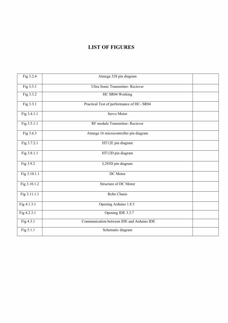
LIST OF FIGURES
Fig 3.2.4 Atmega 328 pin diagram
Fig 3.3.1 Ultra Sonic Transmitter- Reciever
Fig 3.3.2 HC SR04 Working
Fig 3.3.1 Practical Test of performance of HC- SR04
Fig 3.4.1.1 Servo Motor
Fig 3.5.1.1 RF module Transmitter- Reciever
Fig 3.6.3 Atmega 16 microcontroller pin diagram
Fig 3.7.2.1 HT12E pin diagram
Fig 3.8.1.1 HT12D pin diagram
Fig 3.9.2 L293D pin diagram
Fig 3.10.1.1 DC Motor
Fig 3.10.1.2 Structure of DC Motor
Fig 3.11.1.1 Robo Chasis
Fig 4.1.3.1 Opening Arduino 1.8.5
Fig 4.2.3.1 Opening IDE 3.3.7
Fig 4.3.1 Communication between IDE and Arduino IDE
Fig 5.1.1 Schematic diagram

LIST OF TABLES
Fig 3.2.2.1.2 ATmega328 key parameters
Fig 3.9.2 Pin description of L293D

CHAPTER 1
INTRODUCTION
Distance measurement of an object in front or by the side of the moving entity is required in large number of devices. These devices may be small or large and can be quite simple or complicated. Distance measurement has important applications in automotive and industrial applications. The distance measurement through sensors is useful in detecting obstacles. It is the distance measurement feature that allowed to imagine about self-driving cars and robots. The distance measurement application is also used in industries to check fuel levels in aircrafts and commercial transport vehicles .These uses various kinds of sensors and systems. In this project we have implemented such a measurement system which uses a ultrasonic sensor, arduino and server motor. Ultrasonic means of distance measurement is a convenient method compared to traditional one using measurement scales. Ultrasonic sound waves are useful both the air and underwater. Ultrasonic sensors are versatile for the distance measurement and it is quite fast for the common application. The transmitted waves are reflected back from the object and received by the sensor again. This provide for cheapest solution. Any distance measurement application has a sensor circuit and an actuator or display circuit (to perform path change according to the obstacle detection or display the distance reading respectively). In this project we have used RF module to control the robot to demonstrate the project. The limitation of this system is it can detect the range between 2m-4m.
1.1 Problem statement
A low cost distance measurement system using ultrasonic sensor which works good in different light condition and has the capability to detect the both distance and location of the object.
1.2 Necessity of the project
The main objective of the project is to provide useful and low cost measurement system that is easy to configure and handle.

CHAPTER 2
LITERATURE SURVEY
Objects detecting sensors are one of the most basic type of sensors that engineers use. There are several method to make cheap object sensors. These simple sensors are made using a IR Rx /Tx pair or Normal LED and LDR pair . These sensor may be useful for simple requirement but they have the following drawback
1. Cant say anything about the real distance of objects.
2. Give different result for different coloured objects .
3. Need calibration( like setting up a variable resistor).
To solve these problem initially IR Range Finder modules were used but they had small range.
Later to solve all these problem ultrasonic range finder module were used. These modules uses ultrasonic sound waves inaudible to human. These modules consist of ultrasonic transmitter that emits ultrasonic waves, the waves after striking the objects gets reflected back and is detected by the ultrasonic receiver. By measuring the time taken in the whole process we can detect the distance of the object from the sensor.
Ultrasonic sensor can detect the object in the range of 400cm which makes it the ideal for distance measurement application.
These are used in several areas:-
1. Speed check in roads
2. Driverless cars to detect obstacles.
3. Radars for robotics.
4. Fuel level in the tank.

CHAPTER 3
SYSTEM DESCRIPTION
3.1 Components Used
1. Arduino
2. Ultrasonic Sensor(HC-SR04)
3. Servo motor
4. RF module(rf transmitter and receiver 434Mhz)
5. L293D IC
6. HC12E-Encoder IC
7. HC12D-Decoder IC
8. DC motor
9. Robo chasis

3.2 Arduino(uno)
3.2.1 Introduction
Arduino refers to an open-source electronics platform or board and the
software used to program it. An Arduino board can be purchased
preassembled or, because the hardware design is open source, built by hand .
A pre-assembled Arduino board includes a microcontroller, which is
programmed using Arduino programming language and the Arduino
development environment. Arduino programming language is a simplified
from of C/C++ programming language based on what Arduino calls
"sketches," which use basic programming structures, variables and functions.
These are then converted into a C++ program.
3.1.1 Hardware
Arduino is open-source hardware. Most Arduino boards consist of an Atmel 8-bit AVR microcontroller (ATmega8, ATmega168, ATmega328, ATmega1280, ATmega2560) with varying amounts of flash memory, pins, and features. We have arduino with ATmega 328.
3.2.2.1 ATmega328
The ATmega328 is a single-chip microcontroller created by Atmel in the megaAVR family.

3.1.1.1.1 Specification
The Atmel 8-bit AVR RISC-based microcontroller combines 32 kB ISP flash memory with read-while-write capabilities, 1 kB EEPROM, 2 kB SRAM, 23 general purpose I/O lines, 32 general purpose working registers, three flexible timer/counters with compare modes, internal and external interrupts, serial programmable USART, a byte-oriented 2-wire serial interface, SPI serial port, 6-channel 10-bit A/D converter (8-channels in TQFP and QFN/MLF packages), programmable watchdog timer with internal oscillator, and five software selectable power saving modes. The device operates between 1.8-5.5 volts. The device achieves throughput approaching 1 MIPS per MHz.
3.1.1.1.2 Key Parameters
Parameter Value
CPU type 8-bit AVR
Performance 20 MIPS at 20 MHz[2]
Flash memory 32 Kb
SRAM 2 kB
EEPROM 1 kB
Pin count 28-pin PDIP, MLF, 32-pin TQPF, MLF
Maximum operating frequency 20 MHz

Number of touch channels 16
Hardware QTouch Acquisition No
Maximum I/O pins 23
External interrupts 2
USB Interface No
USB Speed –
3.1.2 Features
Microcontroller: ATmega328 Operating Voltage: 5V Input Voltage (recommended): 7-12V Input Voltage (limits): 6-20V Digital I/O Pins: 14 (of which 6 provide PWM output) Analog Input Pins: 6 DC Current per I/O Pin: 40 mA DC Current for 3.3V Pin: 50 mA Flash Memory: 32 KB of which 0.5 KB used by bootloader SRAM: 2 KB (ATmega328) EEPROM: 1 KB (ATmega328) Clock Speed: 16 MHz

3.1.3 Pin diagram
Fig : 3.2.4

3.3 Ultrasonic Sensor
3.3.1 Introduction
The HC-SR04 Ultrasonic Distance Sensor is an inexpensive device that is very useful for robotics and test equipment projects. This tiny sensor is capable of measuring the distance between itself and the nearest solid object.The HC-SR04 can be hooked directly to an Arduino or other microcontroller and it operates on 5 volts. This ultrasonic distance sensor is capable of measuring distances between 2 cm to 400 cm. It’s a low current device so it’s suitable for battery powered devices.
3.3.2 Electrical Parameter
3.3.3 Working
Ultrasonic distance sensors use pulses of ultrasonic sound (sound above the range of human hearing) to detect the distance between them and nearby solid objects. The sensors consist of two main components:
An Ultrasonic Transmitter – This transmits the ultrasonic sound pulses, it operates at 40 KHz
An Ultrasonic Receiver – The receiver listens for the transmitted pulses. If it receives them it produces an output pulse whose width can be used to determine the distance the pulse travelled.The HC-SR04 has the following four connections:
VCC – This is the 5 Volt positive power supply. Trig – This is the “Trigger” pin, the one driven to send the ultrasonic pulses. Echo – This is the pin that produces a pulse when the reflected signal is received. The length
of the pulse is proportional to the time it took for the transmitted signal to be detected. GND – This is the Ground pin.

Fig 3.3.1
The device operates as follows:
1. A 5 volt pulse of at least 10 uS (10 microseconds) in duration is applied to the Trigger pin.2. The HC-SR04 responds by transmitting a burst of eight pulses at 40 KHz. This 8-pulse
pattern makes the “ultrasonic signature” from the device unique, allowing the receiver to discriminate between the transmitted pattern and the ultrasonic background noise.3. The eight ultrasonic pulses travel through the air away from the transmitter. Meanwhile the Echo pin goes high to start forming the beginning of the echo-back signal. 4. If the pulse in NOT reflected back then the Echo signal will timeout after 38 mS (38 milliseconds) and return low. This produces a 38 mS pulse that indicates no obstruction within the range of the sensor.
5. If the pulse IS reflected back the Echo pin goes low when the signal is received. This produces a pulse whose width varies between 150 uS to 25 mS, depending upon the time it took for the signal to be received.
6. The width of the received pulse is used to calculate the distance to the reflected object. Remember that the pulse indicates the time it took for the signal to be sent out and reflected back so to get the distance you’ll need to divide your result in half.

Fig : 3.3.2

The illustration below shows the dimensions of the HC-SR04 Ultrasonic Distance Sensor as well as the effective angle of operation. As you can see the sensor is most accurate when the object to be detected is directly in front of it but you do get a response from objects within a 45 degree “window”. The documentation recommends confining that window to 30 degrees (15 degrees on either side) for accurate readings.
Fig : 3.3.3
3.4 Servo Motor
3.4.1 Definition
A servomotor is a rotary actuator or linear actuator that allows for precise control of angular or linear position, velocity and acceleration. It consists of a suitable motor coupled to a sensor for position feedback.

3.4.2 Mechanism
A servomotor is a closed loop mechanism that uses position feedback to control its motion and final position. The input to its control is a signal (either analogue or digital) representing the position commanded for the output shaft.
The motor is paired with some type of to provide position and speed feedback. In the simplest case, only the position is measured. The measured position of the output is compared to the command position, the external input to the controller. If the output position differs from that required, an error signal is generated which then causes the motor to rotate in either direction, as needed to bring the output shaft to the appropriate position. As the positions approach, the error signal reduces to zero and the motor stops.
Fig: 3.4.1.1

3.5 RF module
3.5.1 Introduction The RF module, as the name suggests, operates at Radio Frequency. An RF module (radio frequency module) is a (usually) small electronic device used to transmit and/or receive radio signals between two devices. In an embedded system it is often desirable to communicate with another device wirelessly. This wireless communication may be accomplished through radio frequency (RF) communication.
3.5.2 Types of RF module
Following are the types of RF module
Transmitter module Receiver module Transceiver module System on a chip module
3.5.3 Mechanism
1. Signal through RF can travel through larger distance.
2. TX/RX pair operates at a frequency of 434 Mhz.
3. An RF transmitter receives serial data and transmits it wirelessly through RF through its antenna connected in pin 4
4. The transmission occurs at the rate of 1kbps-10kbps.
5. We have used RF module to demonstrate our project.
3.5.4 Applications
Vehicle monitoring Remote control Telemetry Small-range wireless network Wireless meter reading Access control systems Wireless home security systems

Fig 3.5.1.1

3.6 HT12E-ENCODER IC
3.6.1 Introduction
HT12E is a 212 series encoder IC (Integrated Circuit) for remote control applications. It is commonly used for radio frequency (RF) applications By using the paired HT12E encoder we can easily transmit 12 bits of parallel data serially.
3.6.2 Working
The HT12E 212 series encoder starts a 4 word transmission cycle upon receiving transmission enable signal on TE input. This output cycle will repeats as long as the transmission is enabled. When the transmission enable (TE) signal switches to HIGH, the encoder output completes the current cycle and stops as shown above. The encoder will be in the Standby mode when the transmission is disabled.

Fig : 3.7.2.1
3.7 HT12D-DECODER
3.7.1 Introduction
HT12D is a 212 series decoder IC (Integrated Circuit) for remote control applications. It is commonly used for radio frequency (RF) wireless communication. By using HT12D decoder we can easily receive 12 bits of parallel data serially.
3.7.2 Working
HT12D decoder will be in standby mode initially i.e, oscillator is disabled and a HIGH on DIN pin activates the oscillator. Thus the oscillator will be active when the decoder receives data transmitted by an encoder. The device starts decoding the input address and data. The decoder matches the received address three times continuously with the local address given to pin A0 – A7. If all matches, data bits are decoded and output pins D8 – D11 are activated. This valid data is indicated by making the pin VT (Valid Transmission) HIGH. This will continue till the address code becomes incorrect or no signal is received.

Fig : 3.8.1.1

3.8 L293D IC
3.8.1 Introduction
L293D IC is a typical Motor Driver IC which allows the DC motor to drive on any direction. This IC consists of 16-pins which are used to control a set of two DC motors instantaneously in any direction.
L293D is a dual H-bridge motor driver integrated circuit (IC). Motor drivers act as current amplifiers and provide a high current signal.
3.8.2 Pin diagram

3.8.3 Pin description
Pin No Function Name
1 Enable pin for Motor 1; active high Enable 1,2
2 Input 1 for Motor 1 Input 1
3 Output 1 for Motor 1 Output 1
4 Ground (0V) Ground
5 Ground (0V) Ground
6 Output 2 for Motor 1 Output 2
7 Input 2 for Motor 1 Input 2
8 Supply voltage for Motors; 9-12V (up to 36V) Vcc 2
9 Enable pin for Motor 2; active high Enable 3,4
10 Input 1 for Motor 1 Input 3
11 Output 1 for Motor 1 Output 3
12 Ground (0V) Ground
13 Ground (0V) Ground
14 Output 2 for Motor 1 Output 4
15 Input2 for Motor 1 Input 4
16 Supply voltage; 5V (up to 36V) Vcc

3.8.4 Working
There are 4 input pins for l293d, pin 2,7 on the left and pin 15 ,10 on the right . Left input pins will regulate the rotation of motor connected across left side and right input for motor on the right hand side. The motors are rotated on the basis of the inputs provided across the input pins as LOGIC 0 or LOGIC 1.
3.9 DC MOTOR
3.9.1 Definition
A DC motor is any of a class of rotary electrical machines that converts direct current electrical energy into mechanical energy.
3.9.2Working
The principle of working of a DC motor is that "whenever a current carrying conductor is placed in a magnetic field, it experiences a mechanical force". The DC motor is a machine that transforms electric energy into mechanical energy in form of rotation. Its movement is produced by the physical behaviour of electromagnetism. DC motors have inductors inside, which produce the magnetic field used to generate movement. An electromagnet, which is a piece of iron wrapped with a wire coil that has voltage applied in its terminals. If two fixed magnets are added in both sides of this electromagnet, the repulsive and attractive forces will produce a torque.

Then, there are two problems to solve: feeding the current to the rotating electromagnet without the wires getting twisted, and changing the direction of the current at the appropriate time. Both of these problems are solved using two devices: a split-ring commutator, and a pair of brushes.
Fig : 3.10.1.1
As it can be seen, the commutator has two segments which are connected to each terminal of the electromagnet, besides the two arrows are the brushes which apply electric current to the rotary electromagnet. In real DC motors it can be found three slots instead of two and two brushes.
Fig : 3.10.1.2
This way, as the electromagnet is moving its polarity is changing and the shaft may keep rotating.

3.10.1 Advantages of DC motor
1. :-> Speed control over a wide range both above and below the rated speed: The attractive feature of the dc motor is that it offers the wide range of speed control both above and below the rated speeds. This can be achieved in dc shunt motors by methods such as armature control method and field control method. This is one of the main applications in which dc motors are widely used in fine speed applications such as in rolling mills and in paper mills.
2. High starting torque: dc series motors are termed as best suited drives for electrical traction applications used for driving heavy loads in starting conditions. DC series motors will have a staring torque as high as 500% compared to normal operating torque. Therefore dc series motors are used in the applications such as in electric trains and cranes.
3. Accurate steep less speed with constant torque: Constant torque drives is one such the drives will have motor shaft torque constant over a given speed range. In such drives shaft power varies with speed.
4. Quick starting, stopping, reversing and acceleration5. Free from harmonics, reactive power consumption and many factors which makes
dc motors more advantageous compared to ac induction motors.
3.10.2 Disadvantages of DC motor
1. High initial cost2. Increased operation and maintenance cost due to presence of commutator and
brush gear3. Cannot operate in explosive and hazard conditions due to sparking occur at brush
( risk in commutation failure).

3.11 ROBO CHASIS
3.11.1 Definition
A chassis is the internal framework of an artificial object, which supports the object in its construction and use. An example of a chassis is a vehicle frame, the underpart of a motor vehicle, on which the body is mounted; if the running gear such as wheels and transmission, and sometimes even the driver's seat, are included, then the assembly is described as a rolling chassis.
.
Fig : 3.11
CHAPTER-4
SOFTWARE DESCRIPTION
a. Arduino IDE
4.1.1 Introduction
Arduino consists of both a physical programmable circuit board (often referred to as a microcontroller) and a piece of software, or IDE (Integrated Development Environment) that runs on your computer, used to write and upload computer code to the physical board.
4.1.2 Programming Language used
First, the Arduino compiler/IDE accepts C and C++ as-is. In fact many of the libraries are written in C++. Much of the underlying system is not object oriented, but it could be. Thus, "The arduino language" is C++ or C.

4.1.3 Getting started with arduino ide
1. Open arduino 1.8.5
Fig 4.1.3.1
2.Go to file menu and select new page.
3. Write program.
4. Compile
5. Upload program to arduino.

4.2 Processing IDE
4.2.1 Introduction
Processing (programming language) Processing is an open-source computer programming language and integrated development environment (IDE) built for the electronic arts, new media art, and visual design communities with the purpose of teaching non-programmers the fundamentals of computer programming in a visual context.
4.2.2 Processing Software
Word processing software is used to manipulate a text document, such as a resume or a report. You typically enter text by typing, and the software provides tools for copying, deleting and various types of formatting.
4.2.3 Getting Started
1. Open processing IDE 3.3.7.
Fig : 4.3.2.1

2.Go to file menu and create new page.
3. Write the code.
4. Run.
4.3 How processing IDE communicate with Arduino IDE?
The Arduino IDE and the Processing IDE will communicate with each other through serial communication. The Processing IDE has a serial library which makes it easy to communicate with the Arduino.
Fig : 4.3.1

CHAPTER 5
METHODOLOGY
5.1 Schematic Diagram
Fig 5.1.1
5.2 Implementation
1.Wireless distance measurement system is used to measure the distance between two object precisely.

In this particular project we are using an ultrasonic sensor to measure the distance and we placed the ultrasonic sensor on the top of a servo motor to rotate it at a range of 15 degree to 165 degree.
So by this angle range upto 400cm distance the ultrasonic senses can locate and measure the distance of any object .
2. Now for the hardware port first we take a male to male jumper wire and connect it with 5V pin and connect the other end to the positive rail of breadboard.
Next we take another male to male jumper wire and connect it to the ‘GND’ pin of Arduino and we connect the other port to negative rail of the breadboard.
After that we connect ‘Vcc’ and ‘GND’ pin of both ultrasonic sensor and servo motor to the positive and negative rail of the breadboard respectively. Next we connect the trigger pin of ultrasonic sensor to ‘pin 9’ of Arduino board and we connect pin of ultrasonic sensor to ‘pin 11’ of Arduino board and we connect the data pin of servo motor to ’pin 12’ of Arduino board. And hence the connection of Arduino is completed.
Next we write the code on Arduino IDE and burn it to the Arduino board.
3. We use ‘processing 3.3.7’ software. It is mainly programming language and environment built for the electronics art and graphics used design.
We use this software to locate the object on the computer screen. And print the distance of the object measured by the ultrasonic sensor.
4. We use ‘processing IDE’ to write the code processing IDE similar to the ‘Arduino IDE’. And the ‘processing IDE’ communicate through serial communication with the ’Arduino IDE’.
5.For the communication process we send the data received from ultrasonic sensor to the serial monitor with the same additional characters. These data in the serial monitor will be later received by the ‘processing IDE’ and hence the communication between Arduino IDE and processing IDE is completed.
6.Now we can see the distance of the object at which angle it is located as well as the location of the object in the monitor.

CHAPTER 6
RESULT
The working model of the proposed distance measurement system using ultrasonic sensor was successfully designed and implemented. The circuit was able to measure distance upto 400cm.The circuit was also able to locate the object. Circuit was tested to measure various distance .It has a fast response. The ultrasonic module works good. By using ultrasonic sensor we were able to reduce cost and increase efficiency. This implementation has been the readily used in the fast growing electronic industry.

CHAPTER 7
APPLICATION
1. Driverless car.
2. Robotics
3. To measure the level of fuel in the aircraft fuel tank.
4. In radar
CHAPTER 8
CONCLUSION AND FUTURE SCOPE
8.1 Conclusion
The objective of this project was to design and implement an wireless distance measurement device using ultrasonic sensor. By using the system we can not only calculate the distance of the object but we can also locate the object.
The following can be concluded from the above project-:
1. The system can calculate the distance of the object without errors.2. The system can locate the object.3. The system provide low cost and efficient solution.
8.2 Future scope
1. We can use humidity sensors in future to measure distance in different environment.
2. Using ultrasonic sensor with better specification we can increase the distance measurement range.
3. This system is used in driverless car to detect obstacle.

CHAPTER 9
REFERENCES
1. Arduino programming – Richard Bloom
2. Arduino robotics – John David Warner
3. Ultrasonic sensor and technology – Stefan Cokis
4. Servo motor and industrial control theory – Raizolla Firozian