
Measurement of Delta-Sigma Converter - DiVA portal427876/FULLTEXT01.pdf · Liu Xiyang Measurement...
30
1 FACULTY OF ENGINEERING AND SUSTAINABLE DEVELOPMENT . Measurement of Delta-Sigma Converter Liu Xiyang 06/2011 Bachelor’s Thesis in Electronics Bachelor’s Program in Electronics Examiner: Niclas Bjorsell Supervisor: Charles Nader
Transcript of Measurement of Delta-Sigma Converter - DiVA portal427876/FULLTEXT01.pdf · Liu Xiyang Measurement...

1
FACULTY OF ENGINEERING AND SUSTAINABLE DEVELOPMENT .
Measurement of Delta-Sigma Converter
Liu Xiyang
06/2011
Bachelor’s Thesis in Electronics
Bachelor’s Program in ElectronicsExaminer: Niclas BjorsellSupervisor: Charles Nader

2

Liu Xiyang Measurement of Delta-Sigma Converter
1
Acknowledgement
Here, I would like to thank my supervisor Charles. Nader, who gave me lots of help and
support. With his guidance, I could finish this thesis work.

Liu Xiyang Measurement of Delta-Sigma Converter
2
Abstract
With today’s technology, digital signal processing plays a major role. It is used widely in
many applications. Many applications require high resolution in measured data to achieve a
perfect digital processing technology. The key to achieve high resolution in digital processing
systems is analog-to-digital converters. In the market, there are many types ADC for different
systems. Delta-sigma converters has high resolution and expected speed because it’s special
structure. The signal-to-noise-and-distortion (SINAD) and total harmonic distortion (THD)
are two important parameters for delta-sigma converters. The paper will describe the theory of
parameters and test method.
Key words: Digital signal processing, ADC, delta-sigma converters, SINAD, THD.

Liu Xiyang Measurement of Delta-Sigma Converter
3
ContentsAcknowledgement................................................................................................................................... 1
Abstract ................................................................................................................................................... 2
1 Introduction ..................................................................................................................................... 1
1.1 Background: ............................................................................................................................ 1
1.2 Aim:......................................................................................................................................... 2
2 ADC Architectures .......................................................................................................................... 3
2.1 Integrating ADCs .................................................................................................................... 3
2.2 Flash ADCs ............................................................................................................................. 3
2.3 Pipelined and Subranging ADCs............................................................................................. 4
2.4 SAR ADCs .............................................................................................................................. 5
2.5 Delta-sigma ADC.................................................................................................................... 6
3 Delta-sigma ADC............................................................................................................................ 8
4 ADC parameters ............................................................................................................................ 11
4.1 Total harmonic distortion (THD) .......................................................................................... 12
4.2 Signal-to-noise-and-distortion radio (SINAD)...................................................................... 13
5 ADC testing theory.........................................................................Error! Bookmark not defined.
5.1 Coherent sampling................................................................................................................. 14
5.2 Sine-wave fitting and testing method.................................................................................... 13
6 Device under test and software...................................................................................................... 16
7 Measurement methods and Evaluation.......................................................................................... 19
7.1 Data Collection and analysis ................................................................................................. 19
7.2 Parameters test function based on MATLAB ....................................................................... 20
8 Results ........................................................................................................................................... 21
9 Conclusions ................................................................................................................................... 23
10 References ................................................................................................................................... 1
11 Appendix A ................................................................................................................................. 2

Liu Xiyang Measurement of Delta-Sigma Converter
1
1 Introduction
1.1 Background
As the development of multimedia technology and the third mobile communication, audio
technology is used widely in our daily life. Every piece of multimedia we access on the
Internet, every CD we play, every time we turn on the radio, listeners hope to have a high
quality audio production.
The modern communication systems are based on complicated signal processing techniques
in the digital domain. The applications of digital signal processing are used widely in hi-fi
audio, TV and radio, mobile phones, voice recognition and the systems which include
communication and retrieval of information. Therefore, digital signal processing plays an
importance role in the development of new generations of communication systems. In the real
world, most signals are analog signal. The analog-to-digital conversion becomes the based
part in digital signal processing. The development of Analog-to-Digital Converter (ADC)
could move forward the system based on digital signal processing. So systems with good
digital signal processing technology require a high resolution ADC.
Nowadays, there are mainly two types ADC according to the ratio of sample frequency fs
and signal bandwidth fbError! Reference source not found.: Nyquist-rate ADC and Over-
sampling ADC. The digital signal is dispersed in amplitude and frequency. There are two
important factors: resolution and speed for ADC. Different digital processing systems need
different ADC architectures. The below Figure 1 shows the application of different types
ADC[3]. In next chapter, the paper will describe the different architecture and its applications
in detail.

Liu Xiyang Measurement of Delta-Sigma Converter
2
Figure 1-ADC applications Therefore, it is very important to find a suitable ADC for audio applications. Nowadays,
most audio measurement systems use Delta-Sigma converters for analog-to-digital conversion
which is the key to improve the quality of digital audio systems.
1.2 Aim
In this paper, the author wants to look for an ADC for audio applications. Describe different
ADC´s architecture and applications. Then, this paper will investigate Delta-Sigma ADCs,
then show how exactly each part of Delta-Sigma converter works in theory. Describe the
definition and formula of Signal to Noise-And-Distortion and Total Harmonic Distortion
which will be measured. Based on above theory knowledge, the paper will show a method for
measurement the parameters: Signal to Noise-And-Distortion and Total Harmonic Distortion.

Liu Xiyang Measurement of Delta-Sigma Converter
3
2 ADC Architectures
In the ADCs market, there are mainly five architectures. Because digital signal is dispersed
in frequency and amplitude domain, there are two important factors for ADC: rate and
resolution. When we choose a suitable architecture for a system, we should consider the rate
and resolution of ADC. In follow sections, there are some description of five architectures. By
the description, we choose Delta-Sigma converter as the best choice for audio systems.
2.1 Integrating ADCs
Integrating ADCs have low speed, low cost and high resolution. The integrating architecture
can avoid line frequency and noise. It converts a low bandwidth analog signal into its digital
representation.
An integrating ADC integrates the input signal with a digital counter. The output counter is
related to the sample amplitude. Figure 2-1 shows how a dual-slope converter works [4]. The
advantage is precision and nonlinearity issues because the reference voltage and sample
voltage integration use the same circuit. However, such architecture has disadvantage that it
need 12 N clock pulses when it reaches to N-bit resolution. This type ADCs is typically
applied in digital panel meters and digital multi-meters.
Figure 2-1 Dual slope integrating ADC architecture [4]
2.2 Flash ADCs
Flash ADCs are the fastest and most expensive converter. It uses a large number of
comparator to achieve multibit conversion directly. Figure 2-2 shows a converter with N-bit
resolution that has 2 N-1 comparators [3]. A change of input voltage will cause the output state

Liu Xiyang Measurement of Delta-Sigma Converter
4
change in many comparators that produces a parallel N-bit output. The number of comparator
is grown exponentially when the resolution is increased. The resolution of converter which is
usually lower than 8 bits is limited by excessive input capacitance and power consumption
because any mismatch can cause static errors [4]. This is applied in video area which need
high speed conversion.
Figure 2-2 Block schema of a flash ADC [4]
2.3 Pipelined and Subranging ADCs
The pipelined ADC has become the most popular ADC architecture for a high samples rate
with resolution of 8 bits to 16 bits. It is based on subranging architectures [4]. Figure 2-3
shows a block of subranging ADC. This type architecture is easy to achieve 8 bits resolution,
however more than 8 bits between two stages can be difficult [3].

Liu Xiyang Measurement of Delta-Sigma Converter
5
Figure 2-3 Subranging ADC [4]
The speed of subraging architecture cannot satisfy our need, so the pipelined architecture is
came out. Figure 2-4 shows how it works. There are many factors that could decide the
architecture of ADC, for example the number of stages, the number of bits and the timing.
Here, an N-bit converter requires only N comparators [4], however the comparators must be
very precise to avoid the errors that are mainly disadvantage of the pipeline architecture.
Figure 2-4 Pipelines ADC architecture [4]
Pipelined and Subranging ADCs are high speed, high resolution, good linearity and low
distortion. However, it has two part extremely complicated circuits that could influence the
dynamic performance and cause additional gain and distortion if circuit has any problem. It is
typically applied on communication systems and Charge-couple Device(CCD) imaging
system [3].
2.4 SAR ADCs
The SAR conversion technique use a comparator to weigh the input voltage against the
output of an N-bit DAC. This architecture achieves final result using the DAC output as a
reference voltage [3]. Figure 2-5 shows SAR ADC architecture.

Liu Xiyang Measurement of Delta-Sigma Converter
6
Figure 2-5 SAR ADC architecture [4]
SAR ADCs is usually for inexpensive applications with medium to high resolution and low
speed less than 5 MS/s. It provides low power consumption and range in resolution from 8
bits to 18 bits [4]. It is typically applied in data acquisition and industrial control.
2.5 Delta-Sigma ADC
Delta-Sigma ADC which is called oversampling converters has very simple structures.
Over-sampling ADC use a higher frequency than Nyquist frequency to sample the data.
Delta-Sigma ADC has been a most effectively way to realize high resolution. The Delta-
Sigma converter is based on the oversampling, noise shaping, and decimation filtering
technology [5]. The Delta-Sigma converters consist of a Delta-Sigma modulator followed by
a digital decimation filter. The structure of Delta-Sigma converter is shown in Figure 2-6. The
input low-bandwidth signals are quantized with low resolution but with high sampling
frequency by modulator. The digital filter increases the ADC resolution to 16 bits or more.
But because the frequency of Delta-Sigma converters is much higher than Nyquist frequency,
it has a small bandwidth. The Delta-Sigma converters could only reach to MHz compared to
Nyquist ADC which could reach to GHz [6] [7]. Hence, Delta-Sigma converter becomes
more and more important in digital signal processing technology. The paper will focus on
Delta-Sigma ADC which is typically applied in audio systems.
In next chapter, oversampling and noise shaping technology will be described which could

Liu Xiyang Measurement of Delta-Sigma Converter
7
reduce noise power and distortion of the system.
Figure 2-6 Delta-Sigma converter architecture [4]

Liu Xiyang Measurement of Delta-Sigma Converter
8
3 Delta-Sigma ADC
Typically, Delta-Sigma ADC includes a Delta-Sigma modulator and a decimation filter. The
Delta-Sigma modulator samples the input signal at a specific frequency which is many times
than the Nyquist rate. This process is called oversampling technology. Through the use of
D/A conversion and feedback, the quantization error is spectrally shaped. This process is
called noise shaping technology. The decimation filter removes the out of band errors and
noise and reduces the output frequency to the Nyquist frequency of the input signal [8].
2.1 Oversampling technology
Because the sample frequency of oversampling is much higher than input signal frequency,
this is better for increasing the resolution of ADC and improving the ratio of signal and noise.
As Figure 3-1 show that when we use Mfs (M which should be an integer is called
oversampling ratio.) The sample frequency, the Nyquist frequency becomes Mfs/2 and the
noise spread from 0 to Mfs/2. Then a digital low pass filter could remove the noise from fs/2
to Mfs/2 which achieves high resolution. In Figure 3-1, Δ is called quantizer step size which is
equal to Δ =1/2 N-1, quantization noise without oversampling (Pe) is equal to Δ 2/12 and
quantization noise with oversampling (Pe1) is equal to Δ 2/12M. Above all, the oversampling
technology disperses the quantization noise to a wide range of frequency band, therefore
reducing the noise power in frequency band and improves the signal-to quantization-noise
ratio [5].
Figure 3-1 Oversampling technology

Liu Xiyang Measurement of Delta-Sigma Converter
9
2.1.2 Noise shaping technology
The noise shaping quantizer is shown in below Figure 3-3. The Figure 3-4 shows a block
diagram of how the system works. In Figure 3-4, there is a first order modulator, so Hz is
equal to 11
1 z
. The integrator is a switched-capacitor discrete-time integrator and A/D
converter is1 bit quantizer which is also called comparator.
Figure 3-3 Block of converter
Figure 3-4 Structure of converter
In Delta-Sigma converter, the quantization error will give back input by feedback converter.
The integrator could regard as a high pass filter for quantization noise. Actually, the analog
filter is low pass for input signal, but high pass for noise signal. Therefore, the modulator
analog filter could be seen as a noise shaping filter which is shown on Figure 3-5.

Liu Xiyang Measurement of Delta-Sigma Converter
10
Figure 3-5 Noise shaping technology
As we can see, Delta-Sigma modulator removes the noise out of band then filtering the
shaping signal. So the higher quantizer order is better for the system. The first-order
modulator has two quantization states, but multidigit-order modulator has N quantization
states. When we increase one order, SNR (Signal-to-Noise Ratio) will increase 6 dB without
increasing sampling frequency. So this could easily achieve high resolution as low sampling
frequency.

Liu Xiyang Measurement of Delta-Sigma Converter
11
4 ADC parameters
The performance parameters of ADCs include static parameters and dynamic parameters.
The dynamic parameters are mainly for measurement of the ADC accuracy when the input
signal is changeable. And they are considered as the main factor which leads to the distortion
and noise of the output signal. The performance is measured depend on the applications.
Table 1 shows critical ADC parameters for different applications. The parameters measured
as they are defined in the IEEE-Standard 1241-2010[4].
Applications Critical ADC parameters
Audio SINAD, THD, noise
Geophysical THD, SINAD, long-term stability, noise
Spectrum analysis SINAD, ENOB, SFDR, noise
Telecommunication SINAD, NPR, SFDR, Big error rate, Word
error rate, noise
Video DNL, SINAD, SFDR, DG, DP, noise
Imaging DNL, INL, SINAD, ENOB, noise, Full-scale
step response, Out-of-range recovery
Table 1- Critical ADC parameters for typical applications [4]
DG=differential gain error DNL=differential nonlinearity
DP=differential phase error ENOB=effective number of bits
INL=integral nonlinearity NPR=noise power ratio
SFDR=spurious free dynamic range
SINAD=signal-to-noise-and-distortion ratio
THD=total harmonic distortion

Liu Xiyang Measurement of Delta-Sigma Converter
12
Since I am looking for an ADC for audio applications, SINAD (signal-to-noise-and-
distortion ratio) and THD (total harmonic distortion) will be chosen and measured in follow
chapter. THD is measured in frequency domain and SINAD is measured in time domain in
my method. The time domain signal is defined as x(n) and the frequency domain signal is
defined as X(f). Fast Fourier Transform in Section 4.1 is used for transferring from x(n) to
X(f).
4.1 Total harmonic distortion (THD)
The root-sum-of-squares (rss) of all the harmonic distortion components including their
aliases in the spectral output of the ADCs for a pure sine-wave input of specified amplitude
and frequency and THD is measured in frequency domain. THD which is often expressed as a
decibel ratio is estimated by the rss of the second through the tenth harmonics [4].
Usually the total harmonic distortion is given by the ratio [4]:
rms
2
h2
1
A
fXMTHD
h
Where
X[fh] is the complex value of the spectral component at frequency fh.
fh is the h times harmonic frequency of the DFT of the ADC output data record.
M is the number of samples in the data record.
h is the set of harmonics over which the sum is taken.
Arms is the rms value of the input sine waves.
During calculation THD, we need to get spectrum power density figure first by FFT method.
FFT which is called Fast Fourier Transform is fast calculation of discrete Fourier transform. It
could save much calculation time.
In MATLAB, it could transform easily by follow code:
spec=(fftshift(fft(data,length(data))/length(data)));
freq=(-length(data)/2:length(data)/2-1)*fs/length(data);
plot(freq,db(abs(spec)));

Liu Xiyang Measurement of Delta-Sigma Converter
13
4.2 Signal-to-noise-and-distortion radio (SINAD)
SINAD which is depends on the amplitude and frequency of the applied sine-wave is the
ratio of root-mean-square (rms) signal to rms noise and distortion (NAD). To find NAD, need
a best-fit sine-wave to the record [4]. NAD is the difference between the fit sine wave to that
record. SINAD is always measured using sine-wave input signal [4].SINAD which is a way to
state dynamic range is negative correlation with THD+noise.
The signal-to-noise-and-distortion ratio, SINAD, is given by
SINAD=NAD
Arms
Where
2
inerms
plitudeWavePeakAmSA
The noise-and-distortion, NAD, is given by
2
1])`[][(
1nxnx
MNAD
M
n
Where
x[n] is the sample data set.
x`[n] is the data set of the best-fir sine wave.
M is the number of samples in the record.
4.3 Sine-wave fitting and testing method
To test parameters, input a large sine wave to ADC. The frequency of input signal is called
fundamental frequency by sine-wave fitting test method. To make sure reduce any error
source this could affect the test result. So a sine wave source needs to be a good short-term
stability [4].
There are a lot of tests which use a sine wave as input signals. One reason is that we could
produce an accurate sine-wave that can be tested with a spectrum analyzer. The other reason
is that sine-wave is linear time invariant system. This means the output signal has same

Liu Xiyang Measurement of Delta-Sigma Converter
14
frequency with input but altered amplitude and phase. The test results give the nonlinear and
time-varying errors [4]
Apply a sine wave to the input of the ADC. Calculate the values of A, B, C that give the
best fit to the recorded signal to a function of the form:
CftBftAnx nn )2sin()2cos(][
Then we use transform theory to calculate the values of A B and C. Convert the x[n] to a
matrix vector form.
C
B
A
fs
Nf
fs
Nf
fs
mf
fs
mf
x
1)1
2cos()1
2cos(
.........
1)2sin()2cos(
Where m is from 0 to N-1 and the two matrixes are called H and . So here x(n)= H .
When solve this equation, we could use the least square solution to find parameters A,B and C
in .
Use MATLAB to solve the value of A B and C by code: XH \ . Then the best fit sine
wave is the function of the form:
]`[nx = )),arctan(2(cos22 CBftBA n
4.4 Coherent sampling
To test parameters, input a pure and large amplitude sine wave signal at frequency fi that is
satisfied the criteria for coherent sampling in order to reduce leakage in the frequency
spectrum by measuring an integer number of periods of the sine wave. For an input signal
frequency f and a desired sample number N, we would like to adjust the ratio of sampling
frequency fs and the number of analog signal cycles M [9].
So coherent sampling frequency is calculated by the formula:
f/fs=M/N

Liu Xiyang Measurement of Delta-Sigma Converter
15
Where
fs is sampling frequency;
M is number of sampled period;
N is number of samples.
This chapter has described the parameters and the testing method theory which is used in
writing Matlab function. The coherent sampling theory is used for testing THD in frequency
domain and sine-wave fitting is used for testing SINAD in time domain. Combined the
formula and testing method, the Matlab functions for testing SINAD and THD could be
written.
Liu Xiyang Measurement of Delta-Sigma Converter
16
5 Device under test and software
Above all are the main parameters needed to be tested when we design an ADC. The fewer
dynamic errors and lower distortion and noise are a goal of ADC design. Because noise and
nonlinearity performance are relevant to resolution of ADCs, ADCs are compared mainly by
resolution, speed. The author use two ways, one is the software provide by TI (Texas
Instruments) and the other is Matlab functions written by own to test SINAD and THD. We
choose ADS1146 ADC as testing equipment.
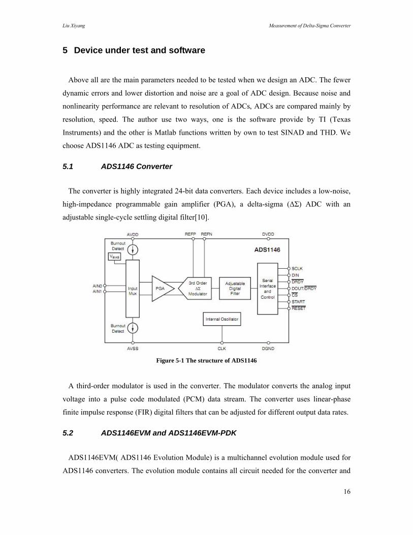
5.1 ADS1146 Converter
The converter is highly integrated 24-bit data converters. Each device includes a low-noise,
high-impedance programmable gain amplifier (PGA), a delta-sigma (ΔΣ) ADC with an
adjustable single-cycle settling digital filter[10].
Figure 5-1 The structure of ADS1146
A third-order modulator is used in the converter. The modulator converts the analog input
voltage into a pulse code modulated (PCM) data stream. The converter uses linear-phase
finite impulse response (FIR) digital filters that can be adjusted for different output data rates.
5.2 ADS1146EVM and ADS1146EVM-PDK
ADS1146EVM( ADS1146 Evolution Module) is a multichannel evolution module used for
ADS1146 converters. The evolution module contains all circuit needed for the converter and

Liu Xiyang Measurement of Delta-Sigma Converter
17
is compatible with the TI (Texas Instruments) Modular EVM System. The connectors connect
the evolution module and the pins of the converters. The evolution module could be plugged
into motherboard to work with personal computers.
ADS1146EVM-PDK which is a converter development kit is controlled completely of
board setting. It could be built in analysis tools including scope and FFT. The data could be
collected to text files by software. This kit combines the evolution module board with the
motherboard, and includes ADCPro™ software for evaluation [10].
The motherboard is used for collection the evolution module to the computer by the USB
port. It is a Modular Evolution Module System motherboard. The motherboard was designed
to be used as a stand-alone demonstration platform for low-speed data converters [10].
Figure 6-2 shows the converter evolution module, motherboard and ADCPro software CD.
Figure 6-3 shows how to connect the converter evolution module to motherboard.
Figure 5-2 Devices [10]
Figure 5-3 Connection the evolution module to motherboard [10]

Liu Xiyang Measurement of Delta-Sigma Converter
18
5.3 ADCpro software
ADCPro which is for evaluating the converter development kit is software for collecting,
recording, and analyzing data from ADC evaluation boards. The software could control the
converter development kit. In this paper, software is used for data collection and analysis data
so that shows SINAD and THD directly. Figure 6-4 shows the software display window.
Figure 5-4 ADCPro software display window

Liu Xiyang Measurement of Delta-Sigma Converter
19
6 Measurement methods and Evaluation
6.1 Data Collection and analysis
ADS1146 convert analog input signal which is given by USB line from PC to digital output
signal which is sent back to PC. Therefore, the PC will receive the data what we want to
collect. The Figure 7-1 show ADS1146 has been connects with PC and ready for data
collection.
Figure 6-1 Configuration setting
As the Figure 7-2 shown, when the sample frequency is 20 kHz and waveform is sine-wave,
the coherent frequency is 4985.35 Hz which is calculated by coherent sampling test theory see
Chapter 4.4.
Figure 6-2 Triple generator parameters setting

Liu Xiyang Measurement of Delta-Sigma Converter
20
Finally, because we will measure the parameters by MATLAB, we need to construct a
recording file to store the data what we want to calculate. Figure 7-3 shows the signal is in
frequency domain. At the same time, the software analysis window will display the result
value of SINAD and THD which is shown in Chapter 7.
Figure 6-3 MultiFFT screen
6.2 Parameters test function based on MATLAB
To test the SINAD and THD of ADS1146 is based on MATLAB software. After collection
data, we need to process the data and calculate it by the formula what have been mentioned in
Chapter 4. Here, the paper will show the programming code based on MATLAB.
To test THD, apply a test signal which is with a pure, large amplitude sine wave at
frequency fi chosen to meet the criteria for coherent sampling [4]. Then use FFT function on
the signal to get the power spectrum density figure. The harmonics of the signal is shown in
the Figure 8-1 clearly.
To test SINAD, apply a sine wave with specified frequency and amplitude to the ADC input.
To find NAD is the first step. Fit a sine wave to the record at the fundamental frequency [4].
We use a curve fitting test method to find the fit sine wave as the way mentioned in Chapter
4.3.
The MATLAB function is shown in Appendix A.

Liu Xiyang Measurement of Delta-Sigma Converter
21
7 Results and discussion
In this chapter, there are two ways to test the parameters, one is by writing Matlab functions
and the other one is by ADCPro software. So this chapter will have two results. Then evaluate
the methods by compared two values.
We import the data what have been collect before and process the data by MATLAB
function. Figure 8-1 shows the power spectrum density graphic.
-1 -0.8 -0.6 -0.4 -0.2 0 0.2 0.4 0.6 0.8 1
x 104
-150
-100
-50
0
50
100power spectrum density graphic
frequency(Hz)
|H(f
)|(dB
)
Figure 7-1 Power spectrum density graphic
By using MATLAB functions, THD is equal to -125.3407dB and SINAD is equal to
49.1113dB.
By software ADCpro, SINAD is equal to 53.54 dB and THD is equal to -113.91dB which is
shown in Figure 8-2.
Figure 7-2 ADCPro software parameters values window

Liu Xiyang Measurement of Delta-Sigma Converter
22
The values we got are quiet good which mean the distortion and noise are very low.Maybe
we could increase the amplitude level to have more distortion when we test parameters. The
analog signal is provided by the computer. The computer give a enough pure digital signal
into the evolution module board and through a DAC module to convert to analog signal as the
input signal of ADC converter. This signal processing lead to a low distortion and noise
results. The values of SINAD are almost same. The difference of THD between two ways is
nearly 11dB which is within error limited. It could be from the way of the formula. And the
evolution module is very sensitive. When we touch or move it, the value could be influenced.
What's more, when we import the data we collect by software, there could be some errors.

Liu Xiyang Measurement of Delta-Sigma Converter
23
8 Conclusions
The paper describe the development background of ADC and the importance of improve the
resolution of converters. By compared with other traditional types of converter, conclude the
Delta-Sigma converter is good choice for system which needs high resolution. Oversampling
and noise shaping technology are the most important advantage for Delta-Sigma converters.
The dynamic parameters measure the quality of an ADC. By measurement parameters value
of converter, improve the understanding of the SINAD and THD.
The first method is test by MATLAB. We use the FFT and coherent sampling frequency
theory to measure THD and use sine-wave to measure SINAD. the SINAD is 49.1113dB and
THD is -125.3407dB. This method is realized by the formula of parameters. It could not be
influence by outside factors. However, each time we change the sampling frequency we need
to collect and import data again which make this method become complicated.
The second method is test by software. We set the parameters, input frequency and
sampling frequency, and get the values, SINAD is equal to 53.54 dB and THD is equal to -
113.91dB. This method is simple and directly. It is very easy to be realized. But it could be
influence by touching or moving the evolution module.
Compared two values got from two methods, SINAD are almost same and THD has 11dB
error. The values are quiet good for audio applications. The error could be from the way of the
formula. And the evolution module is very sensitive. When we touch or move it, the value
could be influenced. What's more, when we import the data we collect by software, there
could be some errors.
Above all, the two methods still a good way to test the ADC converters' parameters. We
could choose the converters for audio applications by the test methods.

Liu Xiyang Measurement of Delta-Sigma Converter
A
14
9 References
[1] H. Russ,"Introduction,"Digital Audio, Coriolis Group, LLC, 2001, ch.1.[2] V. Saeed ,"Introduction,"Advanced Digital Signal Processing and Noise Reduction, 2nd ed.2000, ch.1, pp.1.[3] S. Rapuano, P. Daporite, E. Balestrieri, L. De Vito, S. J. Tilden, S. Max, and J. Blair, "ADC Parameters and Characteristics,"IEEE Instrumentation & Measurement Magazine,vol.8, no.5, pp.44-45, Dec.2005.[4] IEEE Standard for Terminology and Test Methods for Analog-to-Digital Converters, IEEE Std 1241–2010, 2011.[5]H. Jie , C. Yingying , C. Xiaoxin , Y. Dunshan ,"Design and Implementation of ΣΔ AD Converter,"IEEE Electron Devices and Solid-State Circuits, pp.354, 2009.[6]T.Kuo.k,Chen,H.Yeng,"A Wideband CMOS Sigma-delta Modulator with Incremental Data Weighted Averaging,"IEEE Journal of Solid-State Circuit,vol.37,no.1,pp.11-17,Jan.2002.[7]R.Veldhoven,"A Tri-mode Continuous Time Sigma-delta Modulator with Switched-capacitor DAC for a GSM-EDGE CDMA2000 UMTS Receiver,"IEEE International Solid-State Circuits Conference, vol.1, pp.60-477, 2003.[8]I. Galton, H. T. Jensen, "Oversampling Parallel Delta-Sigma Modulator A/D Conversion," IEEE Transactions on Circuits and Systems-analog and Digital Signal Processing,vol. 43,no.12,Dec,1996.[9] D. D. Reynolds and R.A. Slizynski,"Coherent Sampling Digitizer System,"United States Patent 5,708,432,Jan.1998.[10]16-Bit Analog-to-Digital Converters for Temperature Sensors, Texas Instruments, SBAS453C, Apr 2010.

Liu Xiyang Measurement of Delta-Sigma Converter
A
14
10 Appendix A
Matlab function:
N=2^15;fs=20e3; f=4985.35156250000;t=(0:N-1)/fs;
spec=(fftshift(fft(data,length(data))/length(data))); freq=(-length(data)/2:length(data)/2-1)*fs/length(data);figure(1);plot(freq,db(abs(spec)));title('power spectrum density graphic');xlabel('frequency(Hz)');ylabel('|H(f)|(dB)');
harmonic_index=2:10; % number of harmonic freq_harmonic=f*harmonic_index;ind_fund=find(freq==f)for i=1:length(freq_harmonic)ind_harm(i)=find(freq==freq_harmonic(i))endA_rms=abs(spec(ind_fund))spec_harm=spec(ind_harm)THD=10*log10(sqrt((1/N^2)*sum(abs(spec_harm).^2))/A_rms)disp('Total Harmonic Distortion is ')disp(THD)
H=zeros(length(data),3); for ii=1:length(data) H(ii,:)=[cos(2*pi*f*(ii-1)/fs) sin(2*pi*f*(ii-1)/fs) 1]; end data=data(:); theta=H\data data_fit=theta(1)*cos(2*pi*f*t)+theta(2)*sin(2*pi*f*t)+theta(3); data_fit=data_fit(:);plot(abs(data-data_fit))plot(abs(data))hold onplot(abs(data_fit),'r')A_rms2=theta(2)/sqrt(2) y=sum((data-data_fit).^2)NAD=sqrt((1/N)*y)SINAD=10*log10(A_rms2/NAD)disp('Signal-To-Noise and Distortion Ratio is')disp(SINAD)


