Measurement and control - Metartec Ltd - Analogue... · MC / MMC / EMC Power demand meters ... In...
64
Analogue instruments Measurement and control
Transcript of Measurement and control - Metartec Ltd - Analogue... · MC / MMC / EMC Power demand meters ... In...
Analogue instruments
Measurement and control
M1-2
Analogue instruments
Analogue instrumentsIntroduction . . . . . . . . . . . . . . . . . . . . . . . . . . . . . . . . . . . . . . . . . . . . . . . . . . . . . . . . . . . . . . . . . . . . . . . . . . . . . . . . . . . . . . . 4
Product selection table . . . . . . . . . . . . . . . . . . . . . . . . . . . . . . . . . . . . . . . . . . . . . . . . . . . . . . . . . . . . . . . . . . . . . . . . . . . . . . 7EC / EM / EZC / EC FA / CEC 96
Moving iron ammeters (AC) . . . . . . . . . . . . . . . . . . . . . . . . . . . . . . . . . . . . . . . . . . . . . . . . . . . . . . . . . . . . . . . . . . . . . . . . . . 8EC / EM / EZC / ECF / EC FN / CEC 96
Moving iron voltmeters (AC) . . . . . . . . . . . . . . . . . . . . . . . . . . . . . . . . . . . . . . . . . . . . . . . . . . . . . . . . . . . . . . . . . . . . . . . . . 13BC / BM / CBC 96
Moving-coil ammeter (DC) . . . . . . . . . . . . . . . . . . . . . . . . . . . . . . . . . . . . . . . . . . . . . . . . . . . . . . . . . . . . . . . . . . . . . . . . . . 18BC / BM / CBC 96
Moving-coil voltmeter (DC) . . . . . . . . . . . . . . . . . . . . . . . . . . . . . . . . . . . . . . . . . . . . . . . . . . . . . . . . . . . . . . . . . . . . . . . . . . 21BC / BM / ZC
Analogue indicator to measure a process signal . . . . . . . . . . . . . . . . . . . . . . . . . . . . . . . . . . . . . . . . . . . . . . . . . . . . . . . 24MC / MMC / EMC
Power demand meters . Analogue indicator to measure alternating current and its maximeter . . . . . . . . . . . . . . . . . 27HC / HM / HZC
Pointer Frequency meters . . . . . . . . . . . . . . . . . . . . . . . . . . . . . . . . . . . . . . . . . . . . . . . . . . . . . . . . . . . . . . . . . . . . . . . . . . 30HLC
Reed Frequency meters . . . . . . . . . . . . . . . . . . . . . . . . . . . . . . . . . . . . . . . . . . . . . . . . . . . . . . . . . . . . . . . . . . . . . . . . . . . . 32WMC / WTC
Wattmeters . Analogue indicator to measure power . . . . . . . . . . . . . . . . . . . . . . . . . . . . . . . . . . . . . . . . . . . . . . . . . . . . . 34YMC / YTC
Varmeters . Analogue indicator to measure the reactive energy . . . . . . . . . . . . . . . . . . . . . . . . . . . . . . . . . . . . . . . . . . . 39FEM / FETC / FMZ / FTZ
Electronic phase-meters . . . . . . . . . . . . . . . . . . . . . . . . . . . . . . . . . . . . . . . . . . . . . . . . . . . . . . . . . . . . . . . . . . . . . . . . . . . . 43PIC A / PIC B / PIC E
Induction phase-meters . . . . . . . . . . . . . . . . . . . . . . . . . . . . . . . . . . . . . . . . . . . . . . . . . . . . . . . . . . . . . . . . . . . . . . . . . . . . 46PGR
Bidirectional protection wattmeters . . . . . . . . . . . . . . . . . . . . . . . . . . . . . . . . . . . . . . . . . . . . . . . . . . . . . . . . . . . . . . . . . . 502 EC / 2 HC / 2 HLC
Synchronisation and marine applications equipment . . . . . . . . . . . . . . . . . . . . . . . . . . . . . . . . . . . . . . . . . . . . . . . . . . . . 52SMC / STC / UC / CUC
Synchronisation and marine applications equipment . . . . . . . . . . . . . . . . . . . . . . . . . . . . . . . . . . . . . . . . . . . . . . . . . . . . 55Synchro MAX / Synchro MAX PID
Synchronisation and marine applications equipment . . . . . . . . . . . . . . . . . . . . . . . . . . . . . . . . . . . . . . . . . . . . . . . . . . . . 58MEG - 1000
Insulation resistance meter . . . . . . . . . . . . . . . . . . . . . . . . . . . . . . . . . . . . . . . . . . . . . . . . . . . . . . . . . . . . . . . . . . . . . . . . . 61CH
Hours run meter . . . . . . . . . . . . . . . . . . . . . . . . . . . . . . . . . . . . . . . . . . . . . . . . . . . . . . . . . . . . . . . . . . . . . . . . . . . . . . . . . . . 63
Accessories . . . . . . . . . . . . . . . . . . . . . . . . . . . . . . . . . . . . . . . . . . . . . . . . . . . . . . . . . . . . . . . . . . . . . . . . . . . . . . . . . . . . . . 65

M1-3
Measurement and control

Analogue instruments
M1-4
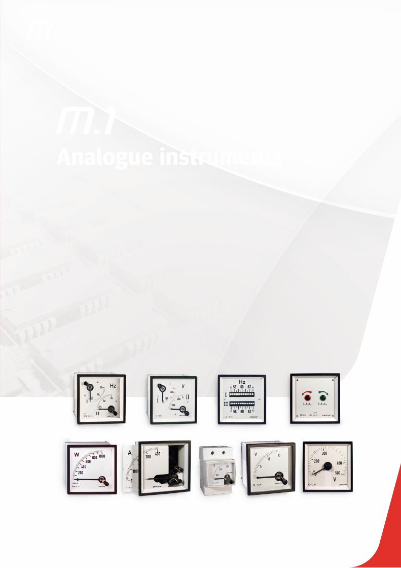
M.1In many applications, such as control and distribution panels, it is important to control the installation quickly and visu-ally, with no need to interpret data to de-tect the installation's status.
CIRCUTOR offers a solution to these needs with this range of products. Ana-logue indicators are essential to display an instantaneous electrical value with a needle that moves through a graduated scale.
Analogue instruments
Definition
The main operation of these instru-ments is provided by the type of measurement system used, either a ferromagnetic system to measure al-ternating current or a magneto-elec-tric system to measure direct current. CIRCUTOR offers equipment for both systems. However, most systems are generally used to measure alternating current.
In general, analogue instruments are used because the interpretation of electrical parameters is quicker and more visual. Therefore, in this case the user simply looks at the position of the needle and does not have to interpret a number on a digital display.
FERROMAGNETIC OR MAGNETO-ELECTRIC
Electric current is directly translated by a measurement element that moves the needle. There are two types of meas-urement elements
Ferromagnetic (AC)
The ferromagnetic indicator is com-posed of a coil that transmits the cur-rent measured, with a fixed iron element and moving iron element in its centre, connected to the instrument's axis and needle. The set moves by the repulsion effect produced by the magnetic field between both iron elements and the arc depends on the current transmitted by
Analogue instruments
M1-5
the coil. This system is used to measure AC and DC voltage and current between 15 and 100 Hz and it measures the root mean square of alternating current. It can not be used to measure rectified and unfiltered AC currents.Magneto-electric (DC)
The magneto-electric indicator is com-posed of a permanent central magnet, surrounded by a magnetic casing that guarantees the insensitivity to the exte-rior magnetic field and there is a mov-ing coil between both, where the nee-dle is fixed. Two spiral springs create the antagonistic pair to move the nee-dle on the scale zero. This system is used to measure DC currents and volt-ages, measuring mean values.
Electrical and mechanical features
Factors that influence the Class
Assembly positionAll instruments will be assembled in a vertical position. They can be sup-plied for vertical or horizontal assem-bly, on demand. The tolerance is ±5º.
Room temperatureThe effects of temperature on the Class depend on the scope of the measure-ment. In general, instruments maintain their Class between +10 and +30ºC. This interval can be lower for particu-larly low measurement scopes. In these cases, the limit values are indicated on the scale.
The instruments can be adjusted for temperatures out of the interval men-tioned above, on demand.Temperature
limits Measurement instruments and their accessories support variations in temperature between -25 and +40 ºC (55 ºC in the tropicalized version) with no permanent defects.
Relative humidityThe Class is maintained within the 25 and 80 % non-condensing relative hu-midity interval.
Magnetic fieldAll instruments maintain their Class un-der the influence of an exterior magnetic field with a value of ≤ 0.5 MV.
Ferromagnetic supportThe nature and thickness of the pan-el's plate does not affect the Class, with the exception of highly sensi-
Insulation voltage
2 kV, 50 Hz, 1min between the mecha-nism and the box and between electri-cally insulated terminals.
Permanent overloadsVoltage circuits: 1.2 Un
Current circuits: 1.2 In (1.5 In for moving iron)
Short duration overloads Voltage circuits: 2 Un during 5 sCurrent circuits:
5 In during 30 s 10 In during 5 s 40 In during 1 s
RelaysContacts: NO / NC Interrupting power: 230 V ac, 8 A / 30 V dc, 5 A resistive load

Analogue instruments
M1-6
tive instruments. In these cases, the scales are marked with the Fe sym-bol, followed by the plate's thickness.
Auxiliary power supplyThe tolerance accepted for the nominal auxiliary power supply values is:
voltage: -15 ... +10 % frequency: 45 ... 65 Hz
VibrationsThe instruments and their accessories support a minimum vibration with an amplitude of ±0.25 mm and a frequency of 50 cycles. Said vibration is equiva-lent to the application of an acceleration equal to 2.5 g to the three perpendicular axes during 20 minutes.
Degree of protectionUnder normal operating conditions, the instrument boxes have an IP 52 protec-tion degree and terminals have an IP 00 protection degree. Optionally, boxes are offered with an IP 54 or IP 55 protection degree and their terminals with an IP 20 protection degree.
PointersIn accordance with DIN 43802.With tube or blade pointers, on demand (Fig. 1)
Tropicalization (TROP)Under TROP operation, and in accord-ance with the DIN 40040 Standard, the instruments are protected against corro-sive environments and support temper-atures between -25 and +55 ºC, with a non-condensing relative humidity of 95 %. Said humidity percentage is stat-ed for a maximum temperature of 30 ºC and 30 days a year; during the rest of the year, the humidity must not exceed 75 %.Within this type of operation, the instruments can be adjusted for refer-ence temperature values above 20 ºC. In these cases, the scales are marked with TROP, followed by the temperature value at which they are adjusted.
ChokesThe instruments and their accessories support five impacts, with an accelera-tion of 15 g, applied in the direction of the three perpendicular axes.
Zero correctionThe regulation of adjustment lengths of the zero corrector on both sides of the
resting position does not exceed ±2 % of the scale length.
BoxesThe boxes and frames of all instruments are made with self-extinguishing ABS material, in compliance with UL 94, and with a high resistance to impacts.The box and frame dimensions com-ply with the DIN 43700 and DIN 43718 Standards, respectively. Bases are made with self-extinguishing rein-forced PPO, in compliance with UL 94, with a high resistance to impacts and a maximum electrical insulation.
StandardsIEC 51, VDE 410, DIN 43780, BS 89, UL 94, EN 60051
CertificatesLloyd’s Register of Shipping (Ask for dif-ferent types).
ScalesIn accordance with the Standards:DIN 43701 for scale end values.DIN 43802 to assess divisions. The di-visions and numbering of standardised scopes follow the examples on Fig.2 and 3.
The scale end values above 1000 are stated in thousands (k).

Analogue instruments
M1-7
Product selection tableS
yste
m
mea
sure
men
t
Fixi
ng
Spe
cific
atio
ns
Type
Ran
ge
Siz
e
Cla
ss
Sca
le a
ngle
Sca
le e
xten
sion
Am
met
ers
HM
Panel
Milliammeter EC 100..0.600 mA 48 x 48, 72 x 72,96 x 96, 144 x 144
1,5
90ºP2
-EC 5...100 A,.../5A
EZC .../5A 72 x 72, 96 x 96
240º
With switch EC FA .../5A
90º
P1With relays CEC .../5A 96 x 96
DIN rail - EM 45 5...60 A, .../5A 85 x 52 P2
BMPanel
- BC 5...60 A, .../60 mV 48 x 48, 72 x 72,96 x 96, 144 x 144
P1With relays CBC .../60 mV 96 x 96
DIN rail - BM 45 5...60 A, .../60 mV 85 x 52
Voltm
eter
s
HM
Panel
-EC 150 ... 600 V, .../110 V 48 x 48, 72 x 72,
96 x 96, 144 x 144
1,5
90º
P1EZC 250 V, 500 V
72 x 72, 96 x 96240º
With switch EC F 150 ... 600 V
90º
With relays CEC 150 ... 600 V, .../110 V 96 x 96
DIN rail - EM 45 300 V, 500 V, .../110 V 85 x 52
BMPanel
- BC 0..0.600 V 48 x 48, 72 x 72,96 x 96, 144 x 144 P2
With relays CBC .../60 mV 96 x 96P1
DIN rail - BM45 15..0.150 V 85 x 52
Pro
cess
in
dica
tors
BMPanel
-
BC 0...10 V, 0/4... 20 mA48 x 48, 72 x 72,
96 x 96, 144 x 144 1,5
90º P2
ZC 0...10 V, 4... 20 mA,.../60 mV 240º
P1DIN rail BM 0...10 V, 0/4... 20 mA 85 x 52 90º
Pow
er d
e-m
and
met
ers
- PanelBimetallic MC
... / 5 A
P1.2
Bimetallic + HM EMC P2
- DIN rail Bimetallic MMC 45 85 x 52 3 P1.2
Ree
d Poi
nter Panel
- HC
45...65 depending on the type
48 x 48, 72 x 72,96 x 96, 144 x 144
0,5
90º
-
- HZC 96 x 96, 144 x 144 240º
DIN rail - HM 85 x 52 90
Ree
ds
Panel - HLC 72 x 72, 96 x 96,144 x 144 -
Watt-meter PanelSingle-phase WMC
400 V, .../5 A 96 x 96, 144 x 144 1,5 90º P1Three-phase WTC
Varmeter PanelSingle-phase YMC
400 V, .../5 A 96 x 96, 144 x 144 1,5 90º P1Three-phase YTC
Pha
se-m
eter
s
Ele
ctro
nic
Panel
Single-phase FEMC
cos ϕ 0.5 - 1 - 0.5
96 x 96, 144 x 144 1,5
90º
P1
Three-phase FETC
Single-phase FMZ240º
Three-phase FTZ
In
duct
ion Single-phase PIC cos ϕ 0 - 1 - 0
90ºThree-phase PIC cos ϕ 0 - 1 - 0

Analogue instruments
M1-8
Analogue indicator to measure alternating current
Moving-coilAmmeter
Application
In alternating current applications, to control the state of the current quickly and visually.
FeaturesDescription
No need for auxiliary power supply, only the CEC 96 type. DIN boxes with dimensions: 48, 72, 96
and 144. Precision class 1.5 Measurement in true root mean square
100 mA ... 100 A Exchangeable scales for EC48, EC72,
EC96, EM 45, EC 72 FA, EC 96 FA The alarm system can be fully configured
for CEC 96
EC EM EZC EC FA CEC 96 with 2 relays
Auxiliary power supply 230 V ac
Consumption - 2.5 V·A
Frequency - 40 ... 90 Hz
Input circuit
Consumption 0.3 ... 1.5 V·A 0.2 V·A
Frequency 20 ... 100 Hz 45 ... 65 Hz
Overloads
1.2 In permanent5 In during 30 s10 In during 5 s40 In during 1 s
1.2 In permanent
Class 1.5 % FS
Ambient conditions
Operating temperature +10 ... +30 ºC + 5 ... +55 ºC
Limit temperature - 25 ... +40 ºC -25 ... +70 ºC
Altitude 2000 m
Build features
Dimensions See the following table
Weight See the following table
Type of box panel DIN rail panel panel panel
Degree of protection:Front panelTerminals
IP 52IP 00
IP 52IP 20
Insulation voltage 2 kV, 50 Hz, 1 min, between the mechanism and the box 3 kV , 50 Hz, 1min
Standards BS 89, EN 60051, IEC 144, UL 94,DIN 43780, IEC 51, UNE 21318, CE
IEC 51, IEC 1010, IEC 529, IEC 255, IEC 278, IEC 414, IEC 144, LLOYD'S (TEST . ESP . No . 1)
Moving iron ammeters (AC)

Analogue instruments
M1-9
References
Moving iron ammeterAnalogue indicator to measure alternating current
Ammeters, 90º
Type EC 48 EC 72 EC 96 EC 144 EM 45
Class 1,5
Scale (mm) 90º , P2
Dimensions (mm)
ab c
484866,2
727249,2
969649,2
14414471,8
855265
Weight (g) 85 180 220 430 142
mA
100 M10111 M10121 M10131 M10142 M10151
150 M10112 M10122 M10132 M10142 M10152
250 M10114 M10124 M10134 M10144 M10154
300 M10115 M10125 M10135 M10145 M10155
400 M10116 M10126 M10136 M10146 M10156
500 M10117 M10127 M10137 M10147 M10157
600 M10118 M10128 M10138 M10148 M10158
A
5 M10212 M10222 M10232 M10242 M10252
10 M10213 M10223 M10233 M10243 M10253
15 M10214 M10224 M10234 M10244 M10254
20 M10215 M10225 M10235 M10245 M10255
25 M10216 M10226 M10236 M10246 M10256
30 M10217 M10227 M10237 M10247 M10257
40 M10218 M10228 M10238 M10248 M10258
50 M10219 M10229 M10239 M10249 M10259
60 M1021A M1022A M1023A M1024A M1025A
75 - M1022B M1023B M1024B -
100 - M1022C M1023C M1024C -
. . ./5 A (*) M10210 M10220 M10230 M10240 M10250
*Scale is not included, except in EC144 (equipment + scale included, indicate transformer ratio).*For exchangeable scales, see Tables. * .../1 A on demand* Different settings, on demand.
Ammeters, 240ºAmmeters with phase switch
Ammeters with 2 relays
Type EZC 72 EZC 96 EC 72 FA EC 96 FA CEC 96
Accuracy class 1,5
Scale (mm) 240º, P2 90or, P1 90or, P2
Dimensions (mm)
ab c
7272
49,2
9696
49,2
7272
49,2
9696
49,2
9696
85,3
Weight (g) 180 220 180 220 435
mA
. . ./5 A (*) M10920 M10930 M10521 M10531 M14810
* EZC 72 / EZC96:Scale included, indicate the transformer ratio.../1 A , on demandDifferent settings, on demand
* EC 72 FA / EC96 FA:Scale not includedExchangeable scales (see tables).../1 A , on demandDifferent settings, on demand
* CEC 96:Scale included, indicate the transformer ratioExchangeable scales (see tables).../1 A , on demand
Moving iron ammeters (AC)

Analogue instruments
M1-10
References
Exchangeable scales, Moving Iron Ammeters
Type SEC 48 SEC 72 SEC 96 SEM 45 SEC 72 FA SEC 96 FA
Equipment EC 48 EC 72 EC 96 EM 45 EC 72 FA EC 96 FA
A
5/5 M102Z2 M102Y2 M102X2 - - -
10/5 M102Z3 M102Y3 M102X3 - - -
15/5 M102Z4 M102Y4 M102X4 - - -
20/5 M102Z5 M102Y5 M102X5 - - -
25/5 M102Z6 M102Y6 M102X6 - - -
30/5 M102Z7 M102Y7 M102X7 - - -
40/5 M102Z8 M102Y8 M102X8 - - -
50/5 M102Z9 M102Y9 M102X9 M105X9 M105Y9 M105X9
60/5 M102ZA M102YA M102XA M105XA M105YA M105XA
75/5 M102ZB M102YB M102XB M102VB M105YB M105XB
100/5 M102ZC M102YC M102XC M102VC M105YC M105XC
125/5 M102ZD M102YD M102XD M102VD M105YD M105XD
150/5 M102ZE M102YE M102XE M102VE M105YE M105XE
200/5 M102ZF M102YF M102XF M102VF M105YF M105XF
250/5 M102ZG M102YG M102XG M102VG M105YG M105XG
300/5 M102ZH M102YH M102XH M102VH M105YH M105XH
400/5 M102ZJ M102YJ M102XJ M102VJ M105YJ M105XJ
500/5 M102ZK M102YK M102XK M102VK M105YK M105XK
600/5 M102ZL M102YL M102XL M102VL M105YL M105XL
750/5 M102ZM M102YM M102XM M102VM M105YM M105XM
800/5 M102ZN M102YN M102XN M102VN M105YN M105XN
1 000/5 M102ZP M102YP M102XP M102VP M105YP M105XP
1 200/5 M102ZQ M102YQ M102XQ M102VQ M105YQ M105XQ
1 500/5 M102ZR M102YR M102XR M102VR M105YR M105XR
2 000/5 M102ZS M102YS M102XS M102VS M105YS M105XS
2 500/5 M102ZT M102YT M102XT M102VT M105YT M105XT
3 000/5 M102ZU M102YU M102XU M102VU M105YU M105XU
4 000/5 M102ZV M102YV M102XV M102VV M105YV M105XV
5 000/5 M102ZW M102YW M102XW M102VW M105YW M105XW
Moving iron ammeterAnalogue indicator to measure alternating current
Moving iron ammeters (AC)

Analogue instruments
M1-11
Moving iron ammeterAnalogue indicator to measure alternating current
Moving iron ammeters (AC)
Coding table
EC
and
EZC
Am
met
ers
M 1 X X X X 0 0 X X X
CodeInternal Code
Setting
Standard 2P 0
1P 1
5P 6
Current input
Standard (... / 5 A) 0
... / 1 A 1
Scales (*)
1 1
5 2
10 3
15 4
20 5
25 6
30 7
40 8
50 9
60 A
75 B
100 C
125 D
150 E
200 F
250 G
300 H
400 J
500 K
600 L
750 M
800 N
1000 P
1200 Q
1500 R
2000 S
2500 T
3000 U
4000 V
5000 W
CEC
Am
met
ers
M 1 X X X X 0 0 X X
CodeInternal Code
Scale
100 C125 D150 E200 F250 G300 H400 J500 K600 L750 M800 N1000 P1200 Q2000 R2500 S
Current input
Standard (.../ 5 A) 0... / 1 A 1
EC S
cale
s an
d A
mm
eter
s an
d EM
sc
ales
M 1 X X X X 0 0 X X
Code Internal Code
Setting
Standard 2P 01P 15P 6
Current input
Standard (.../ 5 A) 0... / 1 A 1
Am
met
ers
and
EC
FA s
cale
s
M 1 X X X X 0 0 X X
CodeInternal Code
SettingStandard 1P 0
5P 6
Current input
Standard (.../ 5 A) 0... / 1 A 1
EC a
nd E
M
Mill
iam
met
ers
M 1 X X X X 0 0 X
CodeInternal Code
SettingStandard 2P 0
1P 15P 6
Analogue instruments
M1-12
Moving iron ammeterAnalogue indicator to measure alternating current
Moving iron ammeters (AC)
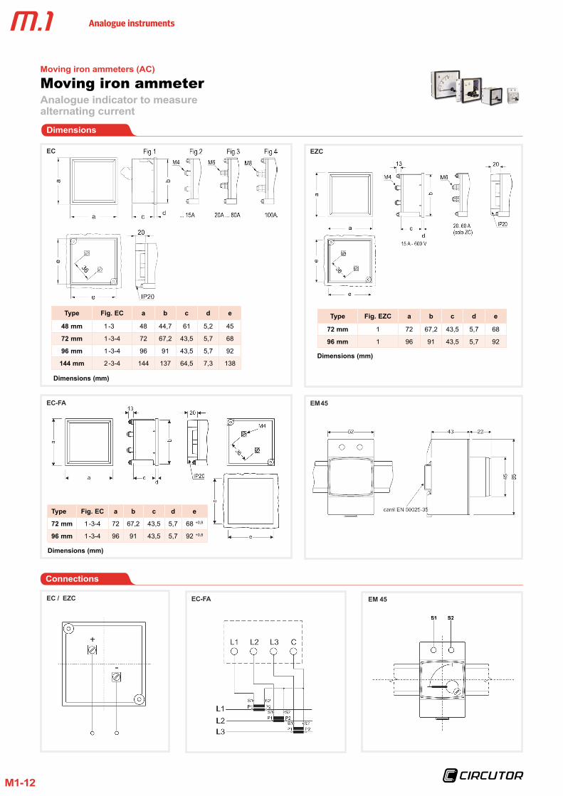
Dimensions
EZC
Type Fig . EC a b c d e
48 mm 1 -3 48 44,7 61 5,2 45
72 mm 1 -3-4 72 67,2 43,5 5,7 68
96 mm 1 -3-4 96 91 43,5 5,7 92
144 mm 2 -3-4 144 137 64,5 7,3 138
Type Fig . EZC a b c d e
72 mm 1 72 67,2 43,5 5,7 68
96 mm 1 96 91 43,5 5,7 92
EC-FA EM 45
EC / EZC EC-FA EM 45
Type Fig . EC a b c d e
72 mm 1 -3-4 72 67,2 43,5 5,7 68 +0,8
96 mm 1 -3-4 96 91 43,5 5,7 92 +0,8
Connections
EC
Dimensions (mm)
Dimensions (mm)
Dimensions (mm)

Analogue instruments
M1-13
Analogue indicator to measure alternating current
Moving iron voltmeter
Application
In alternating current applications, to control the state of the voltage quickly and visually.
FeaturesDescription
No need for auxiliary power supply, only the CEC 96 type DIN boxes with dimensions: 48, 72, 96
and 144 Precision class 1.5 Measurement in true root mean square or
V ... 600 V ac Exchangeable scales for EC48, EC72,
EC96, EM 45 The alarm system can be fully configured
for CEC 96
EC EM EZC EC F EC FN CEC 96
Auxiliary power supply 230 V ac
Consumption - 2.5 V·A
Frequency - 40 ... 90 Hz
Input circuit
Consumption 1 ... 4 V·A 0.2 V·A
Frequency 20 ... 100 Hz 45 ... 65 Hz
Overloads1.5 Un permanent2 Un during 5 s
1.2 Un permanent
Class 1.5 % FS
Ambient conditions
Operating temperature +10 ... +30 ºC + 5 ... +55 ºC
Limit temperature - 25 ... +40 ºC -25 ... +70 ºC
Altitude 2000 m
Build features
Dimensions See the following table
Weight See the following table
Type of box panel DIN rail panel panel panel panel
Degree of protection:Front panelterminals
IP 52IP 00
IP 52IP 20
Insulation voltage 2 kV, 50 Hz, 1 min, between the mechanism and the box 3 kV , 50 Hz, 1min
Standards BS 89, EN 60051, IEC 144, UL 94,DIN 43780, IEC 51, UNE 21318, CE
IEC 51, IEC 1010, IEC 529, IEC 255, IEC 278, IEC 414, IEC 144, LLOYD'S (TEST . ESP . No . 1)
Moving iron voltmeters (AC)

Analogue instruments
M1-14
References
Voltmeters, 90º Voltmeters, 240º Voltmeters with 2 relays
Type EC 48 EC 72 EC 96 EC 144 EM 45 EZC 72 EZC 96 CEC 96
Class 1,5 1,5 1,5
Scale 90º , P1 240º, P1 90º, P1
Dimensions (mm)
abc
4848
66,2
7272
49,2
9696
49,2
144144
71,8
855265
7272
49,2
9696
49,2
9696
85,3
Weight (g) 85 180 220 430 142 180 220 435
V
150 - - - - - - - M14821
250 M10415 M10425 M10435 M10445 - M11125 M11135 M14822
300 M10416 M10426 M10436 M10446 M10456 - - M14823
400 M10417 M10427 M10437 M10447 - - - M14824
500 M10418 M10428 M10438 M10448 M10458 M11128 M11138 M14825
600 M10419 M10429 M10439 M10449 - - - M14826
. . ./110 V(*) M10410 M10420 M10430 M10440 M10450 - - M14820
* EC48 / EC 72 / EC96 / EC144 EM45:*Scale not included, except in EC144 (equipment + scale included, indicate the transformer ratio)*For exchangeable scales, see Tables.*Different secondary voltages, on demand*1P or 1.2P setting, on demand
* EZC 72 / EZC96*Scale included, indicate the transformer ratio*Different secondary voltages, on demand*1P setting, on demand
* CEC 96:Scale included, indicate the transformer ratio
Voltmeters 90º, 240º and with 2 relays
Moving iron voltmeterAnalogue indicator to measure alternating current
Moving iron voltmeter (AC)
Analogue instruments
M1-15
References
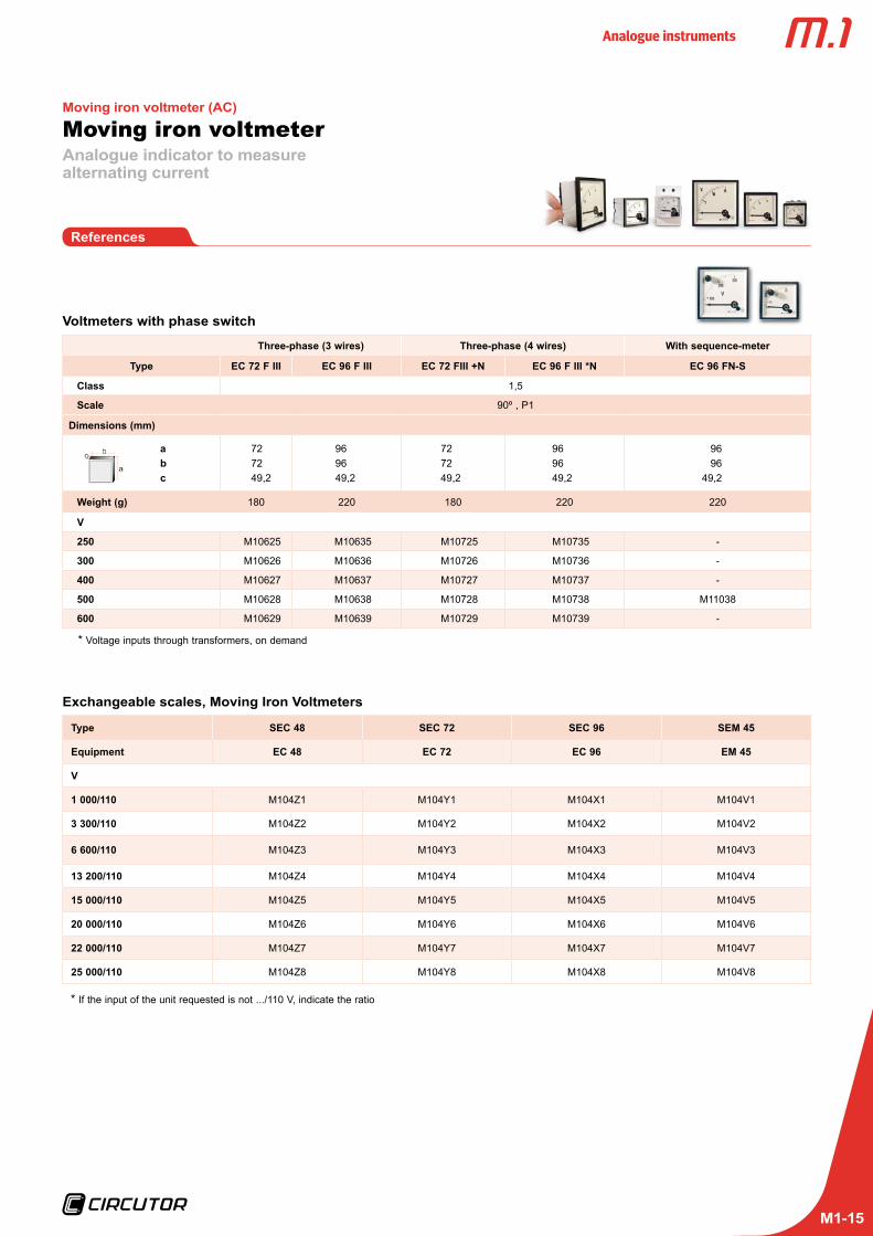
Voltmeters with phase switch
Three-phase (3 wires) Three-phase (4 wires) With sequence-meter
Type EC 72 F III EC 96 F III EC 72 FIII +N EC 96 F III *N EC 96 FN-S
Class 1,5
Scale 90º , P1
Dimensions (mm)
abc
727249,2
969649,2
727249,2
969649,2
9696
49,2
Weight (g) 180 220 180 220 220
V
250 M10625 M10635 M10725 M10735 -
300 M10626 M10636 M10726 M10736 -
400 M10627 M10637 M10727 M10737 -
500 M10628 M10638 M10728 M10738 M11038
600 M10629 M10639 M10729 M10739 -
Exchangeable scales, Moving Iron Voltmeters
Type SEC 48 SEC 72 SEC 96 SEM 45
Equipment EC 48 EC 72 EC 96 EM 45
V
1 000/110 M104Z1 M104Y1 M104X1 M104V1
3 300/110 M104Z2 M104Y2 M104X2 M104V2
6 600/110 M104Z3 M104Y3 M104X3 M104V3
13 200/110 M104Z4 M104Y4 M104X4 M104V4
15 000/110 M104Z5 M104Y5 M104X5 M104V5
20 000/110 M104Z6 M104Y6 M104X6 M104V6
22 000/110 M104Z7 M104Y7 M104X7 M104V7
25 000/110 M104Z8 M104Y8 M104X8 M104V8
* Voltage inputs through transformers, on demand
* If the input of the unit requested is not .../110 V, indicate the ratio
Moving iron voltmeterAnalogue indicator to measure alternating current
Moving iron voltmeter (AC)

Analogue instruments
M1-16
Moving iron voltmeterAnalogue indicator to measure alternating current
Moving iron voltmeter (AC)
Coding table
EC V
oltm
eter
s th
roug
h tr
ansf
orm
er a
nd E
ZC
M 1 X X X X 0 0 X X X
CodeInternal Code
SettingStandard 1.2P 0
1P 1
Voltage input
Standard (.../110 V) 0.../100 V 1.../63.5 V 2.../57.8 V 3
Scales (for
equipment
with inputs
through the
transformer
and all ECs)
1000 13300 26600 313200 415000 520000 622000 725000 8
Dire
ct E
C a
nd E
C F
vo
ltmet
ers
M 1 X X X X 0 0 X
CodeInternal Code
SettingStandard 1P 0
1.2P 2
EC S
cale
s an
d Vo
ltmet
er a
nd E
M s
cale
M 1 X X X X 0 0 X X
CodeInternal Code
SettingStandard 1.2P 0
1P 1
Voltage input
Standard (.../110 V) 0
.../100 V 1
.../63.5 V 2
.../57.8 V 3

Analogue instruments
M1-17
Dimensions
EC EZC
Type Fig . EC a b c d e
48 mm 1 -3 48 44,7 61 5,2 45
72 mm 1 -3-4 72 67,2 43,5 5,7 68
96 mm 1 -3-4 96 91 43,5 5,7 92
144 mm 2 -3-4 144 137 64,5 7,3 138
Type Fig . EZC a b c d e
72 mm 1 72 67,2 43,5 5,7 68
96 mm 1 96 91 43,5 5,7 92
EC-FN / EC-F EM 45
EC / EZC EC-F EM 45
Connections
Moving iron voltmeterAnalogue indicator to measure alternating current
Moving iron voltmeter (AC)
EC-FN
Type Fig . EC a b c d e
72 mm 1 -3-4 72 67,2 43,5 5,7 68 +0,8
96 mm 1 -3-4 96 91 43,5 5,7 92 +0,8
Dimensions (mm)
Dimensions (mm)
Dimensions (mm)

Analogue instruments
M1-18
Analogue indicator to measure direct current
Moving-coilammeter
Application
In direct current applications, to control the state of the current quickly and visually.
FeaturesDescription
No need for auxiliary power supply, only the CEC 96 type DIN boxes with dimensions: 48, 72, 96
and 144 Precision class 1.5 Measurement in DC 25 uA ... 60 A, or ...
60 mV Exchangeable scales for BC48, BC72,
BC96, BM 45 The alarm system can be fully configured
for CBC 96
BC BM CBC 96
Auxiliary power supply 230 V ac
Consumption - 2.5 V·A
Frequency - 40 ... 90 Hz
Input circuit
Consumption 60 mV 0.2 V·A
Overloads
1.2 In permanent5 In during 30 s10 In during 5 s40 In during 1 s
1.2 In permanent5 In during 30 s10 In during 5 s40 In during 1 s
Class 1.5 % FS
Ambient conditions
Operating temperature +10 ... +30 ºC + 5 ... +55 ºC
Limit temperature - 25 ... +40 ºC -25 ... +70 ºC
Altitude 2000 m
Build features
Dimensions See the following table
Weight See the following table
Type of box panel DIN rail panel
Degree of protection:
Front panelterminals
IP 52IP 00
IP 52IP 20
Insulation voltage 2 kV, during 1 min, between the mechanism and the box
Standards BS 89, EN 60051, IEC 144, UL 94, DIN 43780, IEC 51, UNE 21318, CE
IEC51, IEC 1010, IEC 529, IEC 255, IEC 278, IEC 414, IEC 144, LLOYD’S (TEST . ESP . No . 1)
Moving-coil ammeter (DC)

Analogue instruments
M1-19
References
BC: Ammeters 90º / BM: Ammeters 90º, DIN rail / CBC96: Ammeters with 2 relays
Moving-coil ammeterAnalogue indicator to measure direct current
Moving-coil ammeter (DC)
Ammeters, 90º Ammeters with 2 relays
Type BC 48 BC 72 BC 96 BC 144 BM 45 CBC 96
Class 1,5 1,5
Scale 90º , P1 90º , P1
Dimensions (mm)
a b c
4848
66,2
7272
49,2
9696
49,2
14414471,8
855265
9696
85,3
Weight (g) 75 170 210 420 110 435
A
5 M11412 M11422 M11432 M11442 M11452 -
10 M11413 M11423 M11433 M11443 M11453 -
25 M11416 M11426 M11436 M11446 M11456 -
50 M11419 M11429 M11439 M11449 M11459 -
60 - M1142A M1143A M1144A M1145A -
. . ./60 mV(*) M11410 M11420 M11430 M11440 M11450 M14830
Type SBC 48 SBC 72 SBC 96 SBM 45
Equipment BC 48 BC 72 BC 96 BM 45
A / mV
50/60 M114Z9 M114Y9 M114X9 M114V9
60/60 M114ZA M114YA M114XA M114VA
75/60 M114ZB M114YB M114XB M114VB
100/60 M114ZC M114YC M114XC M114VC
150/60 M114ZE M114YE M114XE M114VE
200/60 M114ZF M114YF M114XF M114VF
250/60 M114ZG M114YG M114XG M114VG
300/60 M114ZH M114YH M114XH M114VH
400/60 M114ZJ M114YJ M114XJ M114VJ
600/60 M114ZL M114YL M114XL M114VL
1 000/60 M114ZP M114YP M114XP M114VP
1 500/60 M114ZR M114YR M114XR M114VR
2 500/60 M114ZT M114YT M114XT M114VT
Exchangeable scales
* BC48 / BC 72 / BC96 / BC144 / BM45:*Scale is not included, except in EC144 (equipment + scale included, indicate transformer ratio)*For exchangeable scales, see Tables. External shunts, see M.7 *Different input ranges, shunt*Central zero adjustment, on demand*Inputs starting on 25 uA, on demand
* CEC 96:*Scale included, indicate the transformer ratio (shunt)
* If the input of the unit requested is not .../60mV, indicate the ratio.
BC
and
BM
45 A
mm
eter
s
M 1 X X X X 0 0 X X X
CodeInternal Code
SettingStandard 0
Central zero 1
Shunt input range
Standard (.../60 mV) 0.../50 mV 1
.../150 mV 3
.../300 mV 5
Scales
50 960 A75 B
100 C150 E200 F250 G300 H400 J500 K600 L
1000 P1500 R2500 T
SBC
and
SB
M45
Sca
les
M 1 X X X X 0 0 X X
Code Internal Code
SettingStandard 0
Central zero 1
Shunt input range
Standard (.../60 mV) 0
.../50 mV 1
.../150 mV 3
.../300 mV 5
Coding table
Analogue instruments
M1-20
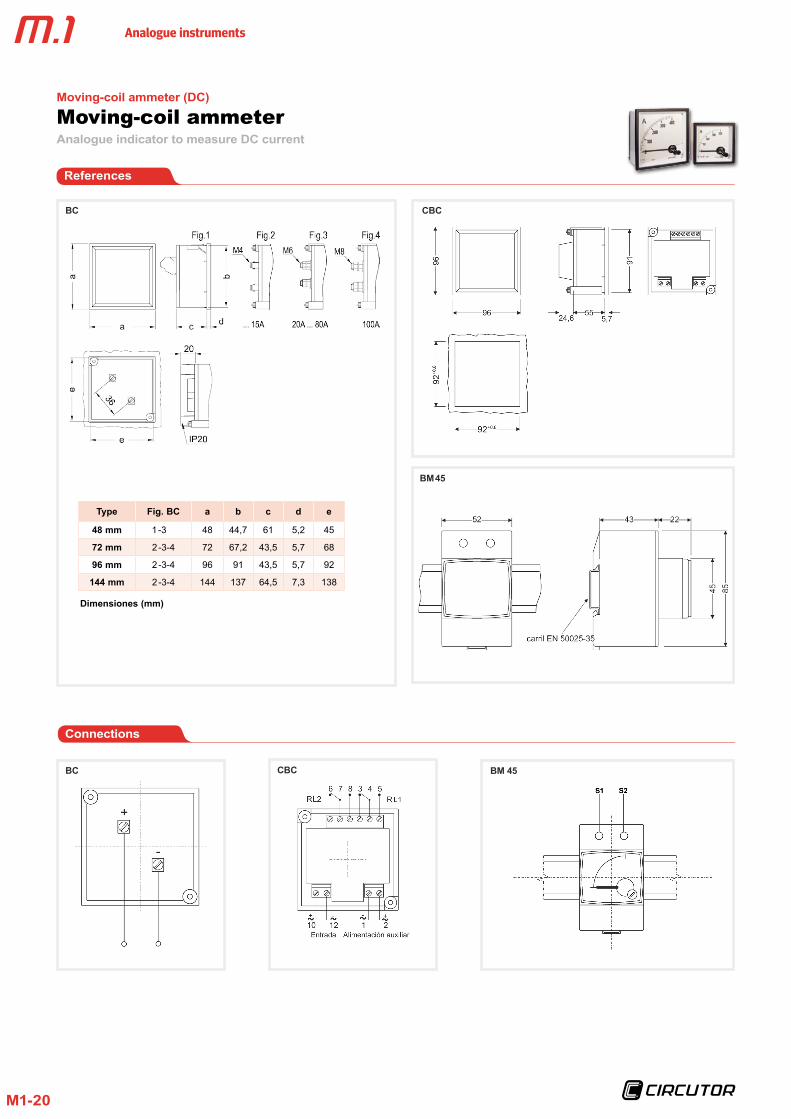
BC
Type Fig . BC a b c d e
48 mm 1 -3 48 44,7 61 5,2 45
72 mm 2 -3-4 72 67,2 43,5 5,7 68
96 mm 2 -3-4 96 91 43,5 5,7 92
144 mm 2 -3-4 144 137 64,5 7,3 138
CBC
BC
Connections
CBC
Moving-coil ammeterAnalogue indicator to measure DC current
Moving-coil ammeter (DC)
References
BM 45
BM 45
Dimensiones (mm)
Analogue instruments
M1-21
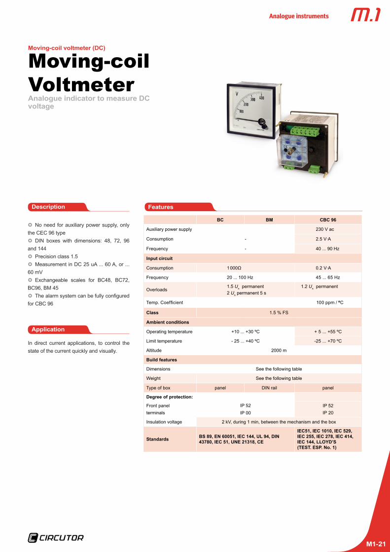
Analogue indicator to measure DC voltage
Moving-coil Voltmeter
Application
In direct current applications, to control the state of the current quickly and visually.
FeaturesDescription
No need for auxiliary power supply, only the CEC 96 type DIN boxes with dimensions: 48, 72, 96
and 144 Precision class 1.5 Measurement in DC 25 uA ... 60 A, or ...
60 mV Exchangeable scales for BC48, BC72,
BC96, BM 45 The alarm system can be fully configured
for CBC 96
Moving-coil voltmeter (DC)
BC BM CBC 96
Auxiliary power supply 230 V ac
Consumption - 2.5 V·A
Frequency - 40 ... 90 Hz
Input circuit
Consumption 1 000Ω 0.2 V·A
Frequency 20 ... 100 Hz 45 ... 65 Hz
Overloads1.5 Un permanent2 Un permanent 5 s
1.2 Un permanent
Temp. Coefficient 100 ppm / ºC
Class 1.5 % FS
Ambient conditions
Operating temperature +10 ... +30 ºC + 5 ... +55 ºC
Limit temperature - 25 ... +40 ºC -25 ... +70 ºC
Altitude 2000 m
Build features
Dimensions See the following table
Weight See the following table
Type of box panel DIN rail panel
Degree of protection:
Front panelterminals
IP 52IP 00
IP 52IP 20
Insulation voltage 2 kV, during 1 min, between the mechanism and the box
Standards BS 89, EN 60051, IEC 144, UL 94, DIN 43780, IEC 51, UNE 21318, CE
IEC51, IEC 1010, IEC 529, IEC 255, IEC 278, IEC 414, IEC 144, LLOYD’S (TEST . ESP . No . 1)

Analogue instruments
M1-22
Moving coil voltmeterAnalogue indicator to measure DC voltage
Moving-coil voltmeter (DC)
*Scale not included, indicate voltage input*Inputs of more than 10 mV, on demand
Voltmeters, 90º Voltmeters with relay
Type BC 48 BC 72 BC 96 BC 144 BM 45 CBC 96
Class 1,5
Scale 90º , P1 90º , P1
Dimensions (mm)
abc
4848
66,2
7272
49,2
9696
49,2
14414471,8
855265
9696
85,3
Weight (g) 75 170 210 420 110 435
V
0 . .0 .10 V M11813 M11823 M11833 M11843 - -
1 M11711 M11721 M11731 M11741 - -
15 M11714 M11724 M11734 M11744 M11754 -
30 M11716 M11726 M11736 M11746 M11755 -
60 M11718 M11728 M11738 M11748 M11756 -
100 M11719 M11729 M11739 M11749 M11757 -
150 M1171A M1172A M1173A M1174A M11758 M14841
250 M1171B M1172B M1173B M1174B - M14842
300 - - - - - M14843
400 M1171D M1172D M1173D M1174D - M14844
500 M1171E M1172E M1173E M1174E - M14845
600 M1171F M1172F M1173F M1174F - M14846
References
BC: Voltmeters 90ºBM: Voltmeters 90º, DIN rail CBC96: Voltmeters with relay 90º
Coding table
BC
and
BM
Voltm
eter
s
M 1 X X X X 0 0 X
CodeInternal Code
SettingStandard 0
Central zero 1

Analogue instruments
M1-23
Moving coil voltmeterAnalogue indicator to measure DC voltage
Moving-coil voltmeter (DC)
BC
Type Fig . BC a b c d e
48 mm 1 -3 48 44,7 61 5,2 45
72 mm 2 -3-4 72 67,2 43,5 5,7 68
96 mm 2 -3-4 96 91 43,5 5,7 92
144 mm 2 -3-4 144 137 64,5 7,3 138
CBC
BC
Connections
CBC
References
BM 45
BM 45
Dimensiones (mm)

Analogue instruments
M1-24
Analogue indicator to measure a process signal
Process indicators
Application
For the measurement of the mean value of voltages and currents in direct current cir-cuits, even of the pulsating type, in a vast margin of values.
FeaturesDescription
Does not need an auxiliary power supply DIN boxes with dimensions: 48, 72, 96
and 144 Precision class 1.5 Measurement in DC of 0 ... 10 V, 0/4 ...
20 mA, .../60 mV Exchangeable scales for BC48, BC72,
BC96, BM 45
BC BM ZC
Input circuit
Consumption 1 000Ω V·A
Overloads1.5 Un permanent2 Un permanent 5 s
Class 1.5 % FS
Ambient conditions
Operating temperature +10 ... +30 ºC
Limit temperature - 25 ... +40 ºC
Altitude 2000 m
Build features
Dimensions See the following table
Weight See the following table
Type of box panel DIN rail panel
Degree of protection:
Front panelterminals
IP 52IP 00
IP 52IP 20
Insulation voltage 2 kV, during 1 min, between the mechanism and the box
Standards BS 89, EN 60051, IEC 144, UL 94, DIN 43780, IEC 51, UNE 21318

Analogue instruments
M1-25
References
BC: Process indicators 90º
Process indicators, 90º
Type BC 48 BC 72 BC 96 BC 144 BM 45
Class 1,5
Scale 90º , P1
Dimensions (mm)
a b c
4848
66,2
7272
49,2
9696
49,2
14414471,8
855265
Weight (g) 75 170 210 420 110
Scope
0 . .0 .10 V M11813 M11823 M11833 M11843 M11853
0 . . .20 mA M11812 M11822 M11832 M11842 M11852
4 . . .20 mA M11811 M11821 M11831 M11841 M11851
. . ./60 mV - - - - -
ZC: Process indicators, 240º
Process indicators, 240º
Type ZC 48 ZC 72 ZC 96 ZC 144
class 1,5
Scale 240º, P1
Dimensions (mm)
a b c
484866,2
727249,2
969649,2
14414471,8
Weight (g) 75 170 210 420
Scope
0 . .0 .10 V M12513 M12523 M12533 M12543
0 . . .20 mA - - - -
4 . . .20 mA M12511 M12521 M12531 M12541
. . ./60 mV M12510 M12520 M12530 M12540
Process indicatorsAnalogue indicator to measure a process signal
Exchangeable scales
Type SIP 48 SIP 72 SIP 96 SIPM 45
Equipment BC 48 BC 72 BC 96 BM 45
Scope
0 . .0 .10 V M118Z3 M118Y3 M118X3 M118V3
0 . . .20 mA M118Z2 M118Y2 M118X2 M118V2
4 . . .20 mA M118Z1 M118Y1 M118X1 M118V1
BC
and
ZC
pro
cess
indi
cato
rs
M 1 X X X X 0 0 X X
CodeInternal Code
SettingStandard 0
Central zero 1
Scale
1 15 2
10 315 420 525 630 740 850 960 A75 B
100 C125 D150 E200 F250 G300 H
400 J500 K600 L750 M800 N
1000 P1200 Q1500 R2000 S2500 T3000 U4000 V5000 W
- 0mA 1A 2kA 3mV 4V 8kV 9rpm A
rpm x 1000 Bl (litres) C
m G
m2 Hm3 J% K
Coding table

Analogue instruments
M1-26
Process indicatorsAnalogue indicator to measure a process signal
Dimensions
BC
Type Fig . BC a b c d e
48 mm 1 -3 48 44,7 61 5,2 45
72 mm 2 -3-4 72 67,2 43,5 5,7 68
96 mm 2 -3-4 96 91 43,5 5,7 92
144 mm 2 -3-4 144 137 64,5 7,3 138
BM
BC / ZC BM
Connections
ZC
Type Fig . ZC a b c d e
48 mm 1 48 44,7 61 5,2 45
72 mm 1 72 67,2 43,5 5,7 68
96 mm 1 96 91 43,5 5,7 92
144 mm 1 144 137 64,5 7,3 138
Dimensiones (mm) Dimensiones (mm)

Analogue instruments
M1-27
Analogue indicator to measure alternating current and its maximeter
Power demand meters
Application
To control the alternating current and meas-ure long overloads in the same unit, integrat-ed within a determined period.
FeaturesDescription
Does not need an auxiliary power supply DIN boxes with dimensions 48, 72, 96
and 144 Class 3 Measurement in AC of .../5 A (on de-
mand.../1 A) Exchangeable scales for MC48, MC72,
MC96, MM 45, EMC72, EMC96 Thermal inertia times of 15 min (on de-
mand, 8 and 30 min)
MC MMC EMC
Input circuit
Consumption 3.25 V·A 4.25 V·A
Overloads1.5 In permanent15 In during 1 s
Accuracy ± 3 % FS ± 3 % Bim.± 1.5 % HM
Ambient conditions
Operating temperature +10 ... +30 ºC
Limit temperature - 25 ... +40 ºC
Altitude 2000 m
Build features
Dimensions See the following table
Weight See the following table
Type of box panel DIN rail panel
Degree of protection:
Front panelterminals
IP 52IP 00
IP 52IP 00
Insulation voltage 2 kV, during 1 min, between the mechanism and the box
Standards BS 89, EN 60051, IEC 144, UL 94, DIN 43780, IEC 51, UNE 21318
Analogue instruments
M1-28
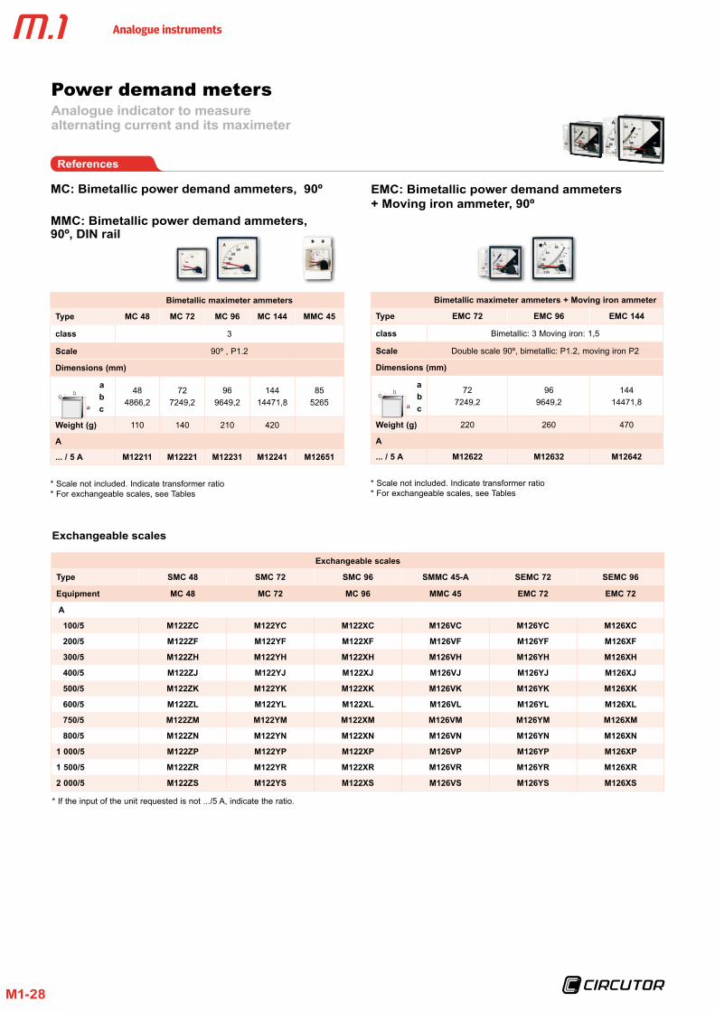
* If the input of the unit requested is not .../5 A, indicate the ratio.
Exchangeable scales
Exchangeable scales
Type SMC 48 SMC 72 SMC 96 SMMC 45-A SEMC 72 SEMC 96
Equipment MC 48 MC 72 MC 96 MMC 45 EMC 72 EMC 72
A
100/5 M122ZC M122YC M122XC M126VC M126YC M126XC
200/5 M122ZF M122YF M122XF M126VF M126YF M126XF
300/5 M122ZH M122YH M122XH M126VH M126YH M126XH
400/5 M122ZJ M122YJ M122XJ M126VJ M126YJ M126XJ
500/5 M122ZK M122YK M122XK M126VK M126YK M126XK
600/5 M122ZL M122YL M122XL M126VL M126YL M126XL
750/5 M122ZM M122YM M122XM M126VM M126YM M126XM
800/5 M122ZN M122YN M122XN M126VN M126YN M126XN
1 000/5 M122ZP M122YP M122XP M126VP M126YP M126XP
1 500/5 M122ZR M122YR M122XR M126VR M126YR M126XR
2 000/5 M122ZS M122YS M122XS M126VS M126YS M126XS
Power demand metersAnalogue indicator to measure alternating current and its maximeter
References
MC: Bimetallic power demand ammeters, 90º
MMC: Bimetallic power demand ammeters, 90º, DIN rail
EMC: Bimetallic power demand ammeters + Moving iron ammeter, 90º
Bimetallic maximeter ammeters
Type MC 48 MC 72 MC 96 MC 144 MMC 45
class 3
Scale 90º , P1.2
Dimensions (mm)
a b c
484866,2
727249,2
969649,2
14414471,8
855265
Weight (g) 110 140 210 420
A
. . . / 5 A M12211 M12221 M12231 M12241 M12651
Bimetallic maximeter ammeters + Moving iron ammeter
Type EMC 72 EMC 96 EMC 144
class Bimetallic: 3 Moving iron: 1,5
Scale Double scale 90º, bimetallic: P1.2, moving iron P2
Dimensions (mm)
a b c
727249,2
969649,2
14414471,8
Weight (g) 220 260 470
A
. . . / 5 A M12622 M12632 M12642
* Scale not included. Indicate transformer ratio* For exchangeable scales, see Tables
* Scale not included. Indicate transformer ratio* For exchangeable scales, see Tables

Analogue instruments
M1-29
Power demand metersAnalogue indicator to measure alternating current and its maximeter
Dimensions
EMC / MC
Type a b c d e
MC 48 48 44,7 61 5,2 45 +0,8
MC 72 72 67,2 43,5 5,7 68 +0,8
EMC 72 72 67,2 57,2 5,7 68 +0,8
EMC 96 96 91 43,5 5,7 92 +0,8
EMC 144 144 137 64,5 7,3 138 +1
MMC
EMC / MC
MMC
Connections
Coding table
MC
and
EM
C P
ower
dem
and
met
ers
and
SMC
and
SEM
C S
cale
s
M 1 X X X X 0 0 X X X
CodeInternal Code
Setting
Standard (15 minutes)
0
8 minutes 130 minutes 2
Current input
Standard (.../ 5 A) 0... / 1 A 1
Scale
100 C125 D150 E200 F250 G300 H
400 J500 K600 L750 M800 N1000 P1200 Q1500 R2000 S2500 T3000 U4000 V5000 W
MM
C 4
5 po
wer
de
man
d
M 1 X X X X 0 0 X
CodeInternal Code
Setting
Standard (15 minutes)
0
8 minutes 1
30 minutes 2
Dimensions (mm)
Analogue instruments
M1-30
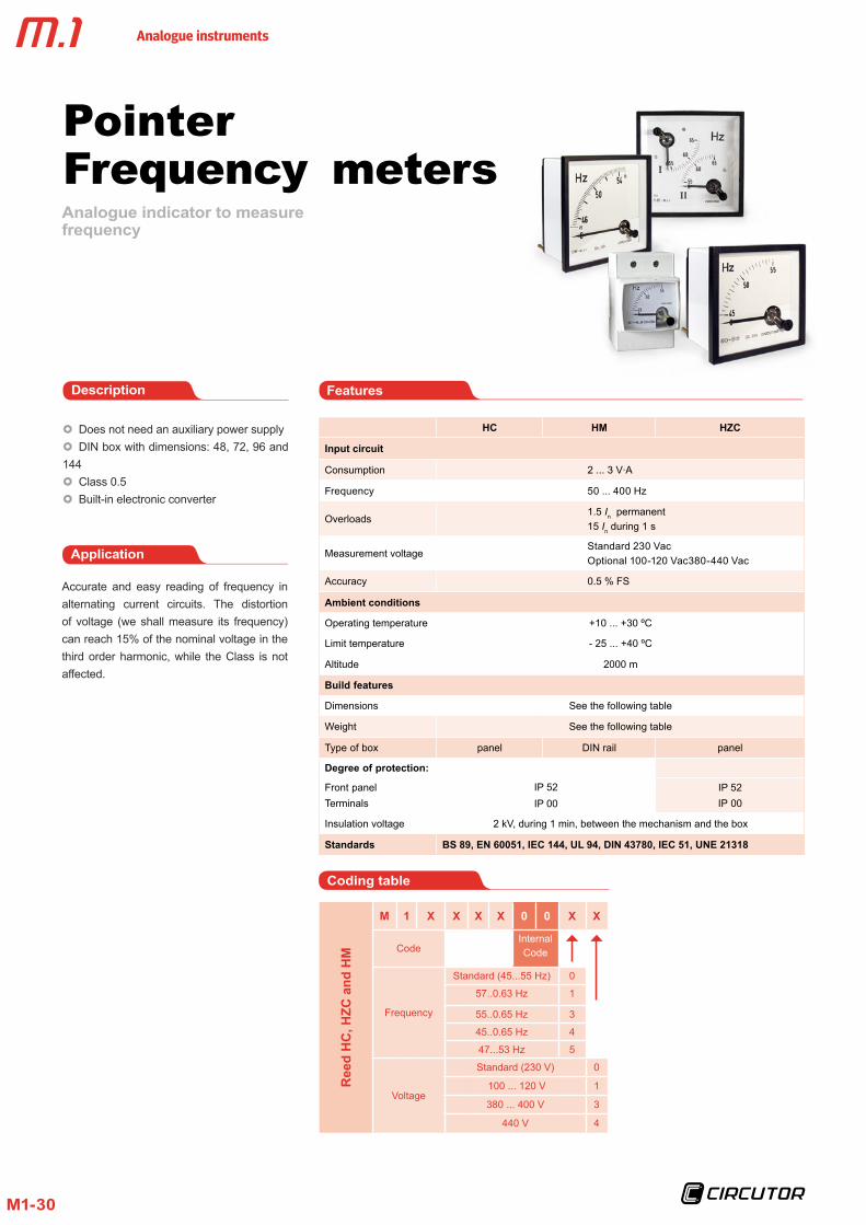
Analogue indicator to measure frequency
PointerFrequency meters
Application
Accurate and easy reading of frequency in alternating current circuits. The distortion of voltage (we shall measure its frequency) can reach 15% of the nominal voltage in the third order harmonic, while the Class is not affected.
FeaturesDescription
Does not need an auxiliary power supply DIN box with dimensions: 48, 72, 96 and
144 Class 0.5 Built-in electronic converter
HC HM HZC
Input circuit
Consumption 2 ... 3 V·A
Frequency 50 ... 400 Hz
Overloads1.5 In permanent15 In during 1 s
Measurement voltageStandard 230 VacOptional 100-120 Vac380-440 Vac
Accuracy 0.5 % FS
Ambient conditions
Operating temperature +10 ... +30 ºC
Limit temperature - 25 ... +40 ºC
Altitude 2000 m
Build features
Dimensions See the following table
Weight See the following table
Type of box panel DIN rail panel
Degree of protection:
Front panelTerminals
IP 52IP 00
IP 52IP 00
Insulation voltage 2 kV, during 1 min, between the mechanism and the box
Standards BS 89, EN 60051, IEC 144, UL 94, DIN 43780, IEC 51, UNE 21318
Coding table
Ree
d H
C, H
ZC a
nd H
M
M 1 X X X X 0 0 X X
CodeInternal Code
Frequency
Standard (45...55 Hz) 0
57..0.63 Hz 1
55..0.65 Hz 3
45..0.65 Hz 4
47...53 Hz 5
Voltage
Standard (230 V) 0
100 ... 120 V 1
380 ... 400 V 3
440 V 4

Analogue instruments
M1-31
Pointer Frequency metersAnalogue indicator to measure frequency
Dimensions
HC
Type a b c d e
48 48 44,7 61 5,2 45 +0,8
72 72 67,2 43,5 5,7 68 +0,8
96 96 91 43,5 5,7 92 +0,8
144 144 137 64,5 7,3 138 +1
Connections
HZC
Type a b c d e
96 96 91 95,5 5,7 92 +0,8
144 144 137 94,7 7,3 138 +1
HM HMHC / HZC
PointerFrequency meters, 90º
Pointer Frequency meters, 240º
Frequency meters, 90º
Type HC 48 HC 72 HC 96 HC 144 HM 45
class 0,5
Scale 90º
Dimensions (mm)
a b c
4848
66,2
7272
49,2
9696
49,2
14414471,8
855265
Weight (g) 95 175 215 425 250
Hz
45 . . .55 M12711 M12721 M12731 M12741 M12751
57 . . .63 M12711001 M12721001 M12731001 M12741001 M12751001
55 . . .65 M12711003 M12721003 M12731003 M12741003 M12751003
45 . . .65 M12711004 M12721004 M12731004 M12741004 M12751004
47 . . .63 M12711005 M12721005 M12731005 M12741005 M12751005
References
Frequency meters, 240º
Type HZC 96 HZC 144
class 0,5
Scale 240º
Dimensions (mm)
a b c
9696
101.2
144144102
Weight (g) 180 520
Hz
45 . . .55 M12831 M12841
57 . . .63 M12831001 M12841001
55 . . .65 M12831003 M12841003
45 . . .65 M12831004 M12841004
47 . . .63 M12831005 M12841005
Dimensions (mm)
Dimensions (mm)

Analogue instruments
M1-32
Analogue indicator to measure frequency
ReedFrequency- meters
Application
Measurement of the frequency in alternating current circuits, for any type of wave shape and under adverse environmental and physi-cal conditions.
FeaturesDescription
Does not need an auxiliary power supply DIN box with dimensions: 72, 96 and
144 mm Class 0.5 Independent measurement of the wave
shape
HLC
Input circuit
Consumption 1 ... 3.6 V·A
Nominal operating
frequency50 or 60 Hz
Overloads1.2 Un permanent2 Un during 5 s
Measurement voltageStandard 230 VacOptional 100...120 Vac / 380...440 Vac
Accuracy 0.5 % FS
Ambient conditions
Operating temperature +10 ... +30 ºC
Limit temperature - 25 ... +40 ºC
Altitude 2000 m
Build features
Dimensions See the following table
Weight See the following table
Type of box panel
Degree of protection:
Front panelTerminals
IP 52IP 00
Insulation voltage 2 kV, during 1 min, between the mechanism and the box
Standards BS 89, EN 60051, IEC 144, UL 94, DIN 43780, IEC 51, UNE 21318

Analogue instruments
M1-33
Reed Frequency metersAnalogue indicator to measure frequency
References
Reed Frequency meters
Type HLC 72 HLC 96 HLC 144
Class 0,5
Dimensions (mm)
a b c
7272
49,2
9696
49,2
14414471,8
Weight (g) 230 300 423
Hz
47 . . .53, 13 reeds
50 Hz
M12921 M12931 M12941
45 . .0 .55, 11 reeds M12921002 M12931002 M12941002
47 . . .53, 7 reeds M12921005 M12931005 M12941005
57 . .0 .63, 13 reeds
60 Hz
M12921001 M12931001 M12941001
55 . .0 .65, 11 reeds M12921003 M12931003 M12941003
57 . .0 .63, 7 reeds M12921004 M12931004 M12941004
Dimensions
HLC
Type a b c d e
72 72 67,2 43,5 5,7 68 +0,8
96 96 91 43,5 5,7 92 +0,8
96 (c) 96 91 57,2 5,7 92 +0,8
144 144 137 64,5 7,3 138 +1
Connections
HLC
Coding table
HLC
Fre
quen
cy m
eter
s
M 1 X X X X 0 0 X X
CodeInternal Code
Frequency / No. reeds
Standard (47...53 Hz/ 13 reeds)
0
57...63 Hz / 13 reeds 145..0.55 Hz / 11
reeds2
55...65 Hz / 11 reeds 357...63 Hz / 7 reeds 4
47..0.53 Hz / 7 reeds 5
Voltage
Standard (230 V) 0 100 ... 120 V 1380 ... 400 V 3
440 V 4
Dimensions (mm)

Analogue instruments
M1-34
Analogue indicator to measure active power
Wattmeters
Application
Measurement of active power in balanced or unbalanced single and three-phase circuits.
FeaturesDescription
Does not need an auxiliary power supply DIN box with dimensions 96 and 144.
Class 1.5 Built-in electronic converter Balanced and unbalanced single and
three-phase circuits.
WMC WTC
Voltage circuit
Voltage 400 V
Consumption 1 ... 4 V·A
Frequency 45 ... 65 Hz
Overloads1.25 Un permanent2 Un during 5 s
Current circuit
Nominal current ... 5 A
Consumption 0.3 ... 1.5 V·A
Frequency 45 ... 65 Hz
Overloads
1.2 In permanent5 In during 30 s10 In during 5 s40 In during 1 s
Accuracy ± 1.5 % FS
Ambient conditions
Operating temperature +10 ... +30 ºC
Limit temperature - 25 ... +40 ºC
Altitude 2000 m
Build features
Dimensions See the following table
Weight See the following table
Type of box panel
Degree of protection:
Front panelTerminals
IP 52IP 00
Insulation voltage 2 kV, during 1 min, between the mechanism and the box
Standards BS 89, EN 60051, IEC 144, UL 94, DIN 43780, IEC 51, UNE 21318

Analogue instruments
M1-35
WattmetersAnalogue indicator to measure active power
References
WMC: Single-phase wattmeters
WTC: Three-phase wattmeters
Balanced three-phase Three-phase 3 wires (ARON) Three-phase (4 wires)
Type WTC 96E WTC 144E WTC 96A WTC 144A WTC 96AN WTC 144AN
Class 1,5
Scale 90º P1 (Simple profile)
Dimensions (mm)
a b c
9696
49,2
144144 71,8
9696
62,9
144144 71,8
9696
62,9
144144 71,8
Weight (g) 290 490 430 640 430 640
U phase-phase 400 V 110 V 400 V
(*)M13032 M13032 M13034 M13044 (*)M13033 M13043
Single-phase
Type WMC 96 WMC 144
Class 1,5
Scale 90º P1 (Simple profile)
Dimensions (mm)
a b c
9696
49,2
144144 71,8
Weight (g) 290 490
U phase-phase 400 V
(*) M13031 M13041
*Scale is NOT included for WMC 96 . For exchangeable scales, see Tables. *Scale included for WMC 144. Indicate the transformer ratio, power and voltage scale base. *Other voltage values, on demand.
*Scale is NOT included for WTC 96E and WTC 96AN. For exchangeable scales, see Tables. *Scale included for WTC 144E, WTC 96A, WTC144A and WTC 144AN. Indicate the transformer ratio, power and voltage scale base. *Other voltage values, on demand.

Analogue instruments
M1-36
WattmetersAnalogue indicator to measure active power
References
Single-phase wattmeters
Three-phase wattmeters
Exchangeable scales
Single-phase
Type SWM 96
Equipment WMC 96
A Scale Base Code
50/5 20 kW M130J9
75/5 - -
100/5 40 kW M130JC
150/5 60 kW M130JE
200/5 80 kW M130JF
300/5 120 kW M130JH
400/5 160 kW M130JJ
500/5 200 kW M130JK
600/5 240 kW M130JL
1 000/5 400 kW M130JP
1 500/5 600 kW M130JR
2 000/5 800 kW M130JS
3 000/5 1.2 MW M130JU
4 000/5 1.6 MW M130JV
5 000/5 2.0 MW M130JW
Exchangeable scales
Exchangeable scales
Three-phase
Type SWT 96E SWT 96AN
Equipment WTC 96E WTC 96AN
A Scale Base Code Code
50/5 30 kW M130K9 M130L9
75/5 50 kW M130KB M130LB
100/5 60 kW M130KC M130LC
150/5 90 kW M130KE M130LE
200/5 120 kW M130KF M130LF
300/5 180 kW M130KH M130LH
400/5 240 kW M130KJ M130LJ
500/5 300 kW M130KK M130LK
600/5 360 kW M130KL M130LL
1 000/5 600 kW M130KP M130LP
1 500/5 900 kW M130KR M130LR
2 000/5 1.2 MW M130KS M130LS
3 000/5 1.8 MW M130KU M130LU
4 000/5 2.4 MW M130KV M130LV
5 000/5 3 MW M130KW M130LW
Analogue instruments
M1-37
WattmetersAnalogue indicator to measure active power
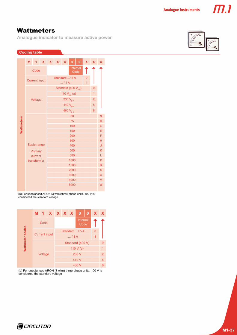
Coding table
Wat
tmet
ers
M 1 X X X X 0 0 X X X
CodeInternal Code
Current inputStandard .../ 5 A 0
... / 1 A 1
Voltage
Standard (400 Vp-p) 0
110 Vp-p (a) 1
230 Vp-p 2
440 Vp-p 5
460 Vp-p 6
Scale range
Primary current
transformer
50 975 B
100 C150 E200 F300 H400 J500 K600 L
1000 P1500 R2000 S3000 U4000 V5000 W
(a) For unbalanced ARON (3 wire) three-phase units, 100 V is considered the standard voltage
Wat
tmet
er s
cale
s
M 1 X X X X 0 0 X X
CodeInternal Code
Current inputStandard .../ 5 A 0
... / 1 A 1
Voltage
Standard (400 V) 0
110 V (a) 1
230 V 2
440 V 5
460 V 6
(a) For unbalanced ARON (3 wire) three-phase units, 100 V is considered the standard voltage

Analogue instruments
M1-38
WattmetersAnalogue indicator to measure active power
Dimensions
WMC / WTC
Type a b c d e
96 E 96 91 43,5 5,7 92 +0,8
96 A / AN 96 91 57,2 5,7 92 +0,8
144 144 137 94,7 7,3 138 +1
WMC
Connections
WTCE
WTCA WTCAN
Dimensions (mm)
Analogue instruments
M1-39
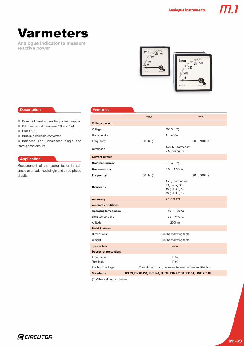
Analogue indicator to measure reactive power
Varmeters
Application
Measurement of the power factor in bal-anced or unbalanced single and three-phase circuits.
FeaturesDescription
Does not need an auxiliary power supply DIN box with dimensions 96 and 144. Class 1.5 Built-in electronic converter Balanced and unbalanced single and
three-phase circuits.
YMC YTC
Voltage circuit
Voltage 400 V (*1)
Consumption 1 ... 4 V·A
Frequency 50 Hz (*1) 20 ... 100 Hz
Overloads1.25 Un permanent2 Un during 5 s
Current circuit
Nominal current ... 5 A (*1)
Consumption 0.3 ... 1.5 V·A
Frequency 50 Hz (*1) 20 ... 100 Hz
Overloads
1.2 In permanent5 In during 30 s10 In during 5 s40 In during 1 s
Accuracy ± 1.5 % FS
Ambient conditions
Operating temperature +10 ... +30 ºC
Limit temperature - 25 ... +40 ºC
Altitude 2000 m
Build features
Dimensions See the following table
Weight See the following table
Type of box panel
Degree of protection:
Front panelTerminals
IP 52IP 00
Insulation voltage 2 kV, during 1 min, between the mechanism and the box
Standards BS 89, EN 60051, IEC 144, UL 94, DIN 43780, IEC 51, UNE 21318
(*1) Other values, on demand

Analogue instruments
M1-40
VarmetersAnalogue indicator to measure reactive power
References
YMC: Varmeters single-phase
*Scale is NOT included for YMC 96. For exchangeable scales, see Tables. *Scale included for YMC 144. Indicate the transformer ratio, power and voltage scale base. *Other voltage values, on demand.
Single-phase
YMC 96 YMC 144
Class 1,5
Scale 90 º P1 (simple profile)
Dimensions (mm)
a b c
9696
49,2
14414471,8
Weight (g) 290 490
Uphase-phase 400 V
Current ... / 5 A
M13231 M13241
YTC: Three-phase varmeters
Balanced three-phase Three-phase 3 wires (ARON) Three-phase (4 wires)
YTC 96E YTC 144E YTC 96A YTC 144A YTC 96AN YTC 144AN
Class
Scale 90 º P1 (simple profile)
Dimensions (mm)
a b c
9696
49,2
14414471,8
9696
62,9
14414471,8
9696
62,9
14414471,8
Weight (g) 290 490 430 640 430 640
Uphase-phase 400 V 110 V 400 V
Current
M13232 M13242 M13234 M13244 M13233 M13243
*Scale is NOT included for YTC 96E and YTC 96AN. For exchangeable scales, see Tables. *Scale included for YTC 144E, YTC 96A, YTC144A and YTC 144AN. Indicate the transformer ratio, power and voltage scale base. *Other voltage values, on demand.
Single-phase varmeters Three-phase varmetersExchangeable scales
Exchangeable scales
Single-phase
Type SYM 96
Equipment YMC 96
A Scale Base Code
50/5 20 kvar M132J9
75/5 - -
100/5 40 kvar M132JC
150/5 60 kvar M132JE
200/5 80 kvar M132JF
300/5 120 kvar M132JH
400/5 160 kvar M132JJ
500/5 200 kvar M132JK
600/5 240 kvar M132JL
1 000/5 400 kvar M132JP
1 500/5 600 kvar M132JR
2 000/5 800 kvar M132JS
3 000/5 1.2 Mvar M132JU
4 000/5 1.6 Mvar M132JV
5 000/5 2.0 Mvar M132JW
Exchangeable scales
Three-phase
Type SYT 96E SYT 96AN
Equipment YTC 96E YTC 96AN
A Code Code
50/5 30 kvar M132K9 M132L9
75/5 45 kvar M132KB M132LB
100/5 60 kvar M132KC M132LC
150/5 90 kvar M132KE M132LE
200/5 120 kvar M132KF M132LF
300/5 150 kvar M132KH M132LH
400/5 240 kvar M132KJ M132LJ
500/5 300 kvar M132KK M132LK
600/5 360 kvar M132KL M132LL
1 000/5 600 kvar M132KP M132LP
1 500/5 900 kvar M132KR M132LR
2 000/5 1.2 Mvar M132KS M132LS
3 000/5 1.8 Mvar M132KU M132LU
4 000/5 2.4 Mvar M132KV M132LV
5 000/5 3.0 Mvar M132KW M132LW

Analogue instruments
M1-41
Dimensions
YMC / YTC
Type a b c d e
96 E 96 91 43,5 5,7 92 +0,8
96 A / AN 96 91 57,2 5,7 92 +0,8
144 144 137 94,7 7,3 138 +1
YMC
Connections
YTCE
YTCA YTCAN
VarmetersAnalogue indicator to measure reactive power
Dimensios (mm)

Analogue instruments
M1-42
Coding table
Varm
eter
s
M 1 X X X X 0 0 X X X
CodeInternal Code
Current inputStandard .../ 5 A 0
... / 1 A 1
Voltage
Standard (400 Vp-p) 0
110 Vp-p (a) 1
230 Vp-p 2
440 Vp-p 5
460 Vp-p 6
Scale range
Primary current
transformer
50 975 B
100 C150 E200 F300 H400 J500 K600 L
1000 P1500 R2000 S3000 U4000 V5000 W
(a) For unbalanced ARON (3 wire) three-phase units, 100V is considered the standard voltage
Varm
eter
sca
les
M 1 X X X X 0 0 X X
CodeInternal Code
Current input
Standard .../ 5 A 0... / 1 A 1
Voltage
Standard (400 V) 0110 V (a) 1
230 V 2440 V 5460 V 6
(a) For unbalanced ARON (3 wire) three-phase units, 100V is considered the standard voltage
VarmetersAnalogue indicator to measure the reactive power

Analogue instruments
M1-43
Analogue indicator to measure cos
ElectronicPhase-meters
Application
Measurement of cos in balanced or unbal-anced single and three-phase circuits.
FeaturesDescription
Does not need an auxiliary power supply DIN box with dimensions 96 and 144 mm Class 1.5 Built-in electronic converter Balanced single and three-phase circuits
FEM / FETC FMZ / FTZ
Voltage circuit
Consumption 1 V·A 4 V·A
Frequency 40 ... 70 Hz
Overloads1.2 Un permanent2 Un during 5 s
Current circuit
Nominal current ... 5 A
Consumption 1.5 V·A 0.75 V·A
Frequency 20 ... 100 Hz
Overloads
1.2 In permanent5 In during 30 s10 In during 5 s40 In during 1 s
Accuracy ± 1.5 % FS
Ambient conditions
Operating tempera-ture +10 ... +30 ºC
Limit temperature - 25 ... +40 ºC
Altitude 2000 m
Build features
Dimensions See the following table
Weight See the following table
Type of box panel
Degree of protection:
Front panelTerminals
IP 52IP 00
Insulation voltage 2 kV, during 1 min, between the mechanism and the box
Standards BS 89, EN 60051, IEC 144, UL 94, DIN 43780, IEC 51, UNE 21318
Analogue instruments
M1-44
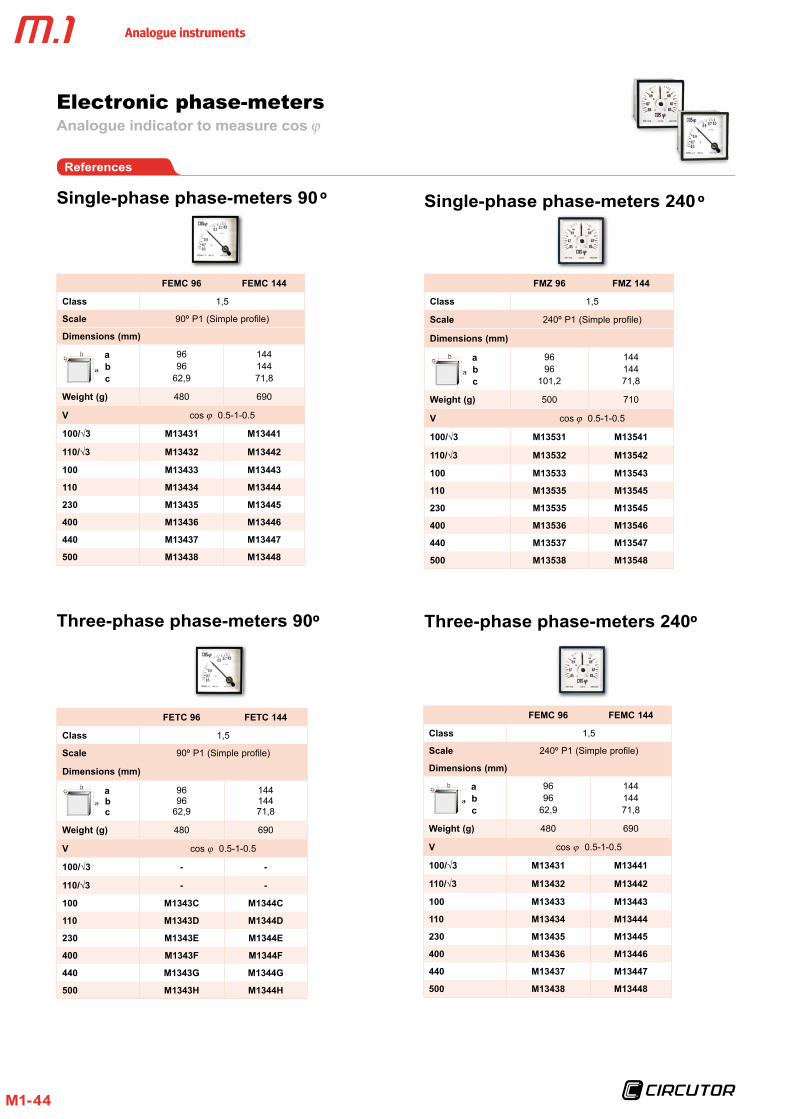
Electronic phase-metersAnalogue indicator to measure cos
References
Single-phase phase-meters 90 º
FEMC 96 FEMC 144
Class 1,5
Scale 90º P1 (Simple profile)
Dimensions (mm)
a b c
9696
62,9
14414471,8
Weight (g) 480 690
V cos 0.5-1-0.5
100/√3 M13431 M13441
110/√3 M13432 M13442
100 M13433 M13443
110 M13434 M13444
230 M13435 M13445
400 M13436 M13446
440 M13437 M13447
500 M13438 M13448
Single-phase phase-meters 240 º
FMZ 96 FMZ 144
Class 1,5
Scale 240º P1 (Simple profile)
Dimensions (mm)
a b c
9696
101,2
14414471,8
Weight (g) 500 710
V cos 0.5-1-0.5
100/√3 M13531 M13541
110/√3 M13532 M13542
100 M13533 M13543
110 M13535 M13545
230 M13535 M13545
400 M13536 M13546
440 M13537 M13547
500 M13538 M13548
Three-phase phase-meters 90º Three-phase phase-meters 240º
FETC 96 FETC 144
Class 1,5
Scale 90º P1 (Simple profile)
Dimensions (mm)
a b c
9696
62,9
14414471,8
Weight (g) 480 690
V cos ϕ 0.5-1-0.5
100/√3 - -
110/√3 - -
100 M1343C M1344C
110 M1343D M1344D
230 M1343E M1344E
400 M1343F M1344F
440 M1343G M1344G
500 M1343H M1344H
FEMC 96 FEMC 144
Class 1,5
Scale 240º P1 (Simple profile)
Dimensions (mm)
a b c
9696
62,9
14414471,8
Weight (g) 480 690
V cos ϕ 0.5-1-0.5
100/√3 M13431 M13441
110/√3 M13432 M13442
100 M13433 M13443
110 M13434 M13444
230 M13435 M13445
400 M13436 M13446
440 M13437 M13447
500 M13438 M13448

Analogue instruments
M1-45
Dimensions
FEMC / FETC
Type a b c d e
96 96 91 57,2 5,7 92 +0,8
144 144 137 64,5 7,3 138 +1
FEMC
Connections
FETC
Electronic phase-metersAnalogue indicator to measure cos
FMZ / FTZ
Type a b c d e
96 96 91 95,5 5,7 92 +0,8
144 144 137 64,5 7,3 138 +1
FMZ
FTZ Coding table
Elec
tron
ic
phas
e-m
eter
s
M 1 X X X X 0 0 X X
CodeInternal Code
Secondary current
Standard .../ 5 A 0... / 1 A 1
FrequencyStandard (50 Hz) 0
60 Hz 1
Dimensions (mm) Dimensions (mm)
Analogue instruments
M1-46
Analogue indicator to measure cos
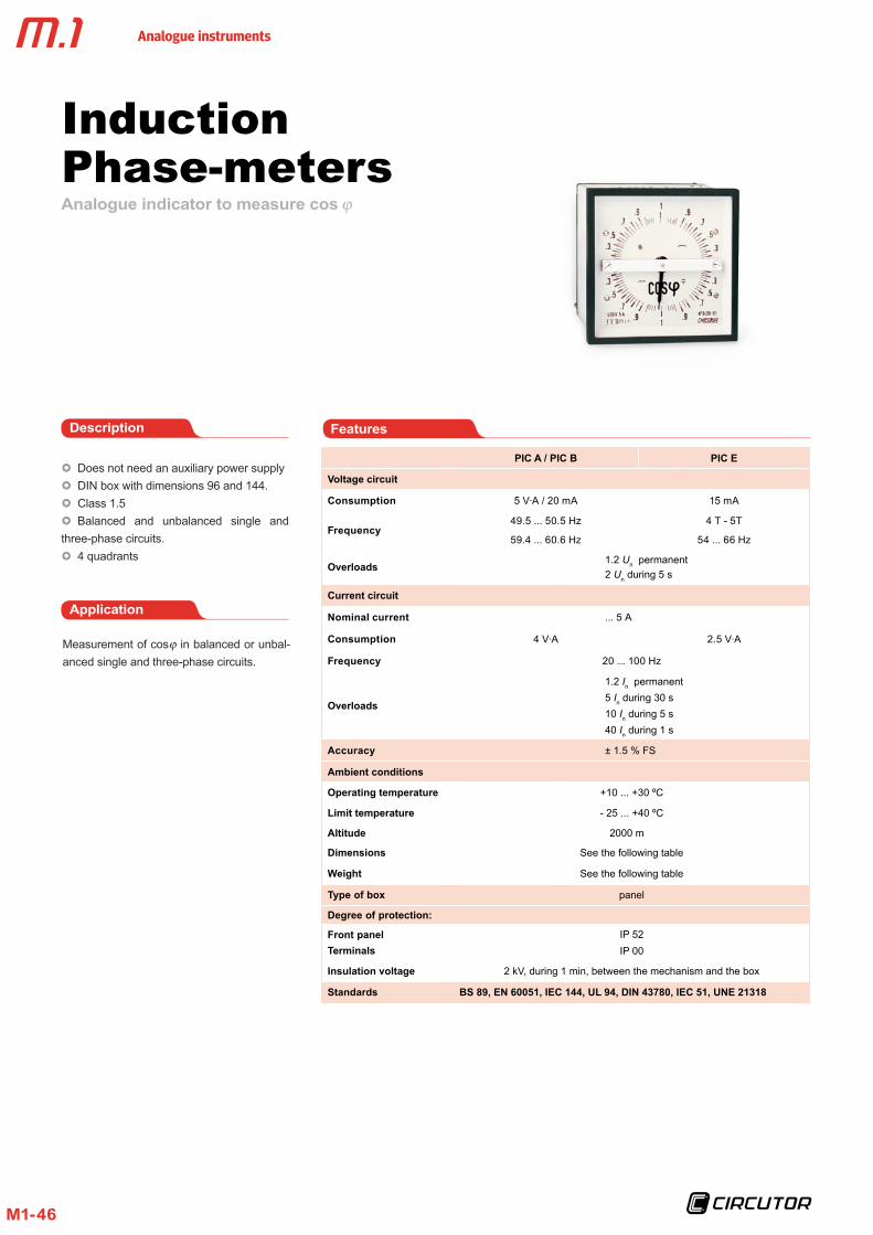
InductionPhase-meters
Application
Measurement of cos in balanced or unbal-anced single and three-phase circuits.
FeaturesDescription
Does not need an auxiliary power supply DIN box with dimensions 96 and 144. Class 1.5 Balanced and unbalanced single and
three-phase circuits. 4 quadrants
PIC A / PIC B PIC E
Voltage circuit
Consumption 5 V·A / 20 mA 15 mA
Frequency49.5 ... 50.5 Hz
59.4 ... 60.6 Hz
4 T - 5T
54 ... 66 Hz
Overloads1.2 Un permanent2 Un during 5 s
Current circuit
Nominal current ... 5 A
Consumption 4 V·A 2.5 V·A
Frequency 20 ... 100 Hz
Overloads
1.2 In permanent5 In during 30 s10 In during 5 s40 In during 1 s
Accuracy ± 1.5 % FS
Ambient conditions
Operating temperature +10 ... +30 ºC
Limit temperature - 25 ... +40 ºC
Altitude 2000 m
Dimensions See the following table
Weight See the following table
Type of box panel
Degree of protection:
Front panelTerminals
IP 52IP 00
Insulation voltage 2 kV, during 1 min, between the mechanism and the box
Standards BS 89, EN 60051, IEC 144, UL 94, DIN 43780, IEC 51, UNE 21318
Analogue instruments
M1-47
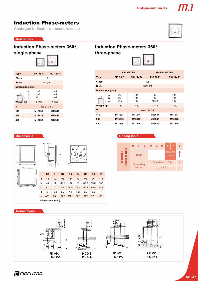
Induction Phase-metersAnalogue indicator to measure cos
References
Type PIC 96 A PIC 144 A
Class 1,5
Scale 360º, P1
Dimensions (mm)
a b c
9696
101,2
144144102
Weight (g) 1 910 1 960
V cos 0-1-0
110 M13631 M13641
230 M13632 M13642
400 M13633 M13643
BALANCED UNBALANCED
Type PIC 96 B PIC 144 B PIC 96 E PIC 144 E
Class 1,5
Scale 360º, P1
Dimensions (mm)
a b c
9696
101,2
144144102
9696
101,2
144144102
Weight (g) 1 410 1 460 1 410 1 460
V cos 0-1-0
110 M13634 M13644 M13637 M13647
230 M13635 M13645 M13638 M13648
400 M13636 M13646 M13639 M13649
Induction Phase-meters 360°, single-phase
Induction Phase-meters 360°, three-phase
Coding table
Indu
ctio
n
Phas
e-m
eter
s
M 1 X X X X 0 0 X
CodeInternal Code
Secondary current
Standard .../ 5 A 0
... / 1 A 1
Dimensions
Connections
C0 C1 C2 C3 C4 C5 C6 C7
a 48 72 96 144 72 96 96 144
b 44 66 89,6 137 66 89,6 89,6 137
c 41 43 43 64,5 57,2 57,2 95,5 94,7
d 5 5,2 5,2 7,1 5,2 5,2 5,2 7,1
e 45+1 68+1 92+1 138+1 68+1 92+1 92+1 138+1
Dimensions (mm)

Analogue instruments
M1-48
Analogue indicator to measure three-phase current
Bidirectional protectionwattmeters
Application
Description
Electronic instrument on the front panel (96x96) used to protect generators against overloads and inverse power. The instru-ment is composed of a power converter with an analogue output connected to the needle indicator with 2 relays. The unit measures and indicates the system's power constantly (measurement in 4 quadrants), sending an alarm signal when the power exceeds the set trip values. The alarm is indicated by activat-ing the output relays. The two LEDS on the front panel can be used to view the status of output relays. The scale is exchangeable.
The instrument has two independent re-lays: an overload and an inverse power relay.
Overload protection
The protection has these characteristics:
Trip point adjustable between 0 and 100% of the scale base power Hysteresis adjustable between 1 and 50%
of the scale base Delay adjustable between 0 and 30 s Inverse power protection. With various
generators connected in parallel, one can start consuming power and working as a motor, under determined situations ("motori-zation"). The relay is activated when the cir-cumstances are met.
The protection system has the following characteristics:Trip point adjustable between 0 and 20% of the scale base power
Delay is adjustable between 0 and 30 s. Relay interlocking* (latch): when the
Features
PGR
Input circuit
Nominal current In 0 ... 20 mA dc
Current measurement range 0 ... 130 % In
Current overload 5 In permanent
Impedance 3 Ω
Auxiliary power supply
Nominal value in AC 115 / 230 / 400 V
Frequency 40 ... 80 Hz
Consumption 2.5 V·A
Nominal value in DC 9-18 / 18-36 / 36-72 / 90-140 V
Consumption 2.5 V·A
Ambient conditions
Operating temperature +5 ... +55 ºC
Limit temperature - 25 ... +70 ºC
Altitude 2000 m
Build features
Dimensions (mm) 96 x 96 x 77.2
Weight (g) 435
Type of box DIN rail
Degree of protection:
Front panelTerminals
IP 52IP 20
Standards BS 89, EN 60051, IEC 144, UL 94, DIN 43780, IEC 51, UNE 21318
alarm condition is met, the relay is activated until the instrument's auxiliary power supply is not shut down (even when the alarm con-ditions disappear) Fault security: the relay bypass position
is the same as when the alarm is triggered. Therefore, when the auxiliary power supply is shut down, the unit sends an alarm.
*: The system can be supplied with no relay interlocking (latch), on demand.

Analogue instruments
M1-49
Bidirectional protection wattmetersAnalogue indicator to measure three-phase current
References
Single-phase wattmeters Three-phase wattmeters
PGR 96 M
Converter (See catalogue M2) CW-M
Class 1,5
Scale 90º , P2
U / I 100 ... 500 V
100 . . .500 V . . ./5 A (*) M14721
PGR 96E PGR 96A PGR 96AN
Converter (See catalogue M2) CW-TE CW-TA CW-TAN
Class 1,5
Scale 90º , P2
U / I 100 ... 500 V
100 . . .500 V . . ./5 A (*) M14722 M14724 M14723
PGR
Wat
tmet
er
M 1 X X X X 0 0 X X X
Code Internal Code
Scales
50 960 A75 B
100 C125 D150 E200 F250 G300 H400 J500 K600 L750 M800 N
1000 P1200 Q1500 R2000 S2500 T3000 U4000 V5000 W
Current input
Standard (.../ 5 A) 0... / 1 A 1
Auxiliary power supply
Standard 220...240 V 0
380 ... 400 V 40/60 Hz 3
Coding table Dimensions
PGR
Connections

Analogue instruments
M1-50
Application
Description
Does not need an auxiliary power supply DIN box with dimensions 96 and 144 mm Class 1.5 Double scale
2 ECDouble moving iron voltmeter (AC)For the measurement and comparison of al-ternating currents from two generators or a generator in the network, when connected in parallel.
2 HCDouble Pointer frequency-meterFor the measurement and easy comparison of frequencies in alternating current circuits coming from generators or between the net-work and generator, when connected in par-allel.
2 HLCDouble reed frequency-meterFor the measurement and easy comparison of frequencies in alternating current circuits coming from generators or between the net-work and generator, when connected in par-allel. The measurement is independent of the wave shape.
For applications in severe environmental and physical conditions.
Features
2 EC 2 HC 2 HLC
Input circuit
Consumption 1 ... 4 V·A 2 ... 3 V·A 1 ... 3.6 V·A
Working frequency 20 ... 100 Hz depending on the type (see table)
Overloads1.2 Un permanent2 Un during 5 s
Measurement voltageStandard 230 VacOptional 100-120 Vac380-440 Vac
Accuracy 1.5 % FS 0.5 % FS
Ambient conditions
Operating temperature +10 ... +30 ºC
Limit temperature - 25 ... +40 ºC
Altitude 2000 m
Build features
Dimensions See the following table
Weight See the following table
Type of box panel
Degree of protection:
Front panelTerminals
IP 52IP 00
IP 52IP 00
Insulation voltage 2 kV, during 1 min, between the mechanism and the box
Standards BS 89, EN 60051, IEC 144, UL 94, DIN 43780, IEC 51, UNE 21318
Synchronisation and marine applications equipment2 EC / 2 HC / 2 HLC

Analogue instruments
M1-51
References
2 EC: Double voltmeter
Type 2 EC 96 2 EC 144
Class 1,5
Scale 90º
Dimensions (mm)
a b c
9696
49,2
14414471,8
Weight (g) 220 430
V
2 x . . ./100 M13831 M13841
2 x . . ./110 M13832 M13842
2 x 220 M13833 M13843
2 x 380 M13834 M13844
2 x 440 M13835 M13845
2 HC: Double Pointer frequency meter
Type 2 HC 96 2 HC 144
Class 0,5
Scale 90º
Dimensions (mm)
abc
9696
62,9
14414471,8
Weight (g) 400 450
Hz
45 . . .55 M12732 M12742
57 . . .63 M12732001 M12742001
55 . . .65 M12732003 M12742003
45 . . .65 M12732004 M12742004
47 . . .63 M12732005 M12742005
2 HLC: Double reed frequency meter
Type 2 HLC 96 2 HLC 144
Class 0,5
Scale -
Dimensions (mm)
abc
9696
62,9
14414471,8
Weight (g) 400 450
Hz
47 . . .53, 13 reeds M12932 M12942
57 . .0 .63, 13 reeds M12932001 M12942001
45 . .0 .55, 11 reeds M12932002 M12942002
55 . .0 .65, 11 reeds M12932003 M12942003
57 . .0 .63, 7 reeds M12932004 M12942004
47 . . .53, 7 reeds M12932005 M12942005
Class 1.5 Class 0.5 Built-in electronic converter
Class 0.5 Independent measurement of the wave shape
Coding table
Dou
ble
voltm
eter
s
M 1 X X X X 0 0 X
Code Internal Code
Nominal scale value
(Scale base)
400 (640) 0440 (700) 1660 (1050) 2
1000 (1600) 31200 (1920) 42500 (4000) 53000 (4800) 63300 (5280) 74000 (6400) 85000 (8000) 95500 (8800) A6500 (10560) B7200(11520) C9000 (14400) D10000 (16000) E11000 (17600) F12500 (20000) G15000 (24000) H20000 (32000) J22000 (35200) K24000 (38400) L25000 (40000) M
2HLC
Fre
quen
cy m
eter
s
M 1 X X X X 0 0 X X
CodeInternal Code
Frequency / No. reeds
Standard (47...53 Hz/ 13 reeds)
0
57...63 Hz / 13 reeds
1
45..0.55 Hz / 11 reeds
2
55...65 Hz / 11 reeds
3
VoltageStandard (400 V) 0
100 ... 120 V 1440 V 4
2 EC / 2 HC / 2 HLCSynchronisation and marine applications equipment
2HC
Freq
uenc
y met
ers
M 1 X X X X 0 0 X X
CodeInternal Code
Frequency
Standard (45...55 Hz) 057..0.63 Hz 155..0.65 Hz 345..0.65 Hz 447...53 Hz 5
Voltage
Standard (230 V) 0 100 ... 120 V 1380 ... 400 V 3
440 V 4

Analogue instruments
M1-52
Dimensions
2 EC
2 EC / 2 HC / 2 HLC
2 EC / 2 HC / 2 HLCSynchronisation and naval application equipment
Type a b c d e
96 mm 96 91 43,5 5,7 92+0,8
144 mm 144 137 64,5 7,3 138+1
2 HC / 2 HLC
Type a b c d e
96 mm 96 91 57,2 5,7 92+0,8
144 mm 144 137 64,5 7,3 138+1
Connections
Dimensions (mm)
Dimensions (mm)

Analogue instruments
M1-53
Description
SMC / STCSynchroscopes Does not need an auxiliary power supply DIN box with dimensions: 96 and 144 mm Class 1 For single and three-phase circuits
UC / CUCSequence-meters Does not need an auxiliary power supply DIN box with dimensions: 72 and 96 mm Class 1.5 Built-in voltage relay Low consumption
Features
SMC STC UC CUC
Input circuit
Consumption Line: 5 V·AGenerator: 15 mA
Line: 20 mA per circuit
Generator: 15 mA per circuit
3 mA 4 V·A
Frequency 20 ... 100 Hz 50 Hz
Overloads1.2 Un permanent2 Un during 5 s
Measurement voltageStandard 230 VacOptional 100-120 Vac380-440 Vac
Accuracy 1.5 % FE
Ambient conditions
Operating temperature + 10 . . . + 30 ºC 0 ... 70 ºC
Front panel - 25 . . . + 40 ºC - 40 . . . + 70 ºC
Altitude 2000 m
Build features
Dimensions See the following table
Weight See the following table
Type of box panel
Degree of protection:
Front panelterminals
IP 52IP 00
IP 52IP 00
Insulation voltage 2 kV, during 1 min, between the mechanism and the box
Standards BS 89, EN 60051, IEC 144, UL 94, DIN 43780, IEC 51, UNE 21318
Synchronisation and marine applications equipment
SMC / STC / UC / CUC

Analogue instruments
M1-54
Application
SMC / STCSynchroscopesTo provide a correct reading of the difference between the frequency and phase angle be-tween two generators or a generator and the network, when connected in parallel. When the difference is zero, the instrument's nee-dle does not move from the synchronisation mark located in the centre of the scale.
The instrument scale is divided in two ar-eas marked with the (+) and (-) signs. These signs indicate whether the machine being connected has a higher or lower frequency that the other one, respectively.
Synchronism is achieved when the needle is on the (-) side, slowly turning towards (+).
The needle of the instrument starts to turn in the correct direction when the difference in frequencies is 1.5 Hz for three-phase sys-tems or 0.5 Hz for single-phase systems .
UC / CUCSequence-metersThe UC 72 and UC 96 types indicate the or-der of three-phase systems.
The CUC 96 type indicates the sequence of phases and it has a built-in relay with a switched and voltage-free contact. The relay is deactivated in the absence of voltage or when the order of phases is incorrect.
A fully electronic circuit, with no moving parts, for the activation of neon indicators.
Scales:A GREEN and RED display indicate whether the phase sequence is CORRECT or IN-CORRECT, respectively.
SMC / STC / UC / CUCSynchronisation and marine applications equipment
References
SM / STC: Single-phasesynchroscopes
SM / STC: Three-phasesynchroscopes
Type STC 96 STC 144Class 1,5
Dimensions (mm) a
bc
9696
101,2
144144102
Weight (g) 1410 1960
V110 M14435 M14445230 M14436 M14446400 M14437 M14447500 M14438 M14448
Type SMC 96 SMC 144Class 1,5
Dimensions (mm) a
bc
9696
101,2
144144102
Weight (g) 1700 2250
V110 M14431 M14441230 M14432 M14442400 M14433 M14443500 M14434 M14444
UC / CUC: Sequence-meters
Type UC 72 UC 96 CUC 96Control relay NO YES
Dimensions (mm) a
bc
727262,9
969662,9
969662,9
Weight (g) 200 275 375
V100 . . .500 V M13721 M13731 -230 - - M13734400 - - M13735
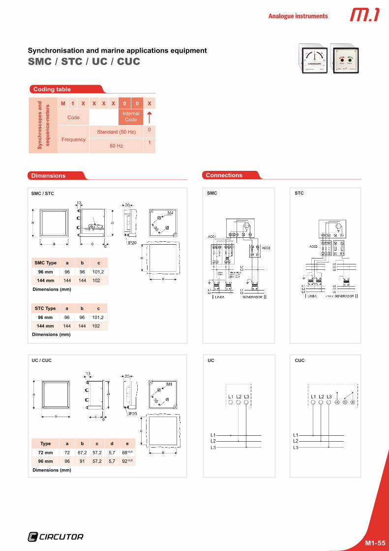
Analogue instruments
M1-55
SMC / STC / UC / CUCSynchronisation and marine applications equipment
Dimensions
SMC / STC
UC / CUC
Type a b c d e
72 mm 72 67,2 57,2 5,7 68+0,8
96 mm 96 91 57,2 5,7 92+0,8
Sync
hros
cope
s an
d se
quen
ce-m
eter
s M 1 X X X X 0 0 X
CodeInternal Code
FrequencyStandard (50 Hz) 0
60 Hz1
Coding table
Connections
SMC STC
UC CUC
SMC Type a b c
96 mm 96 96 101,2
144 mm 144 144 102
STC Type a b c
96 mm 96 96 101,2
144 mm 144 144 102
Dimensions (mm)
Dimensions (mm)
Dimensions (mm)
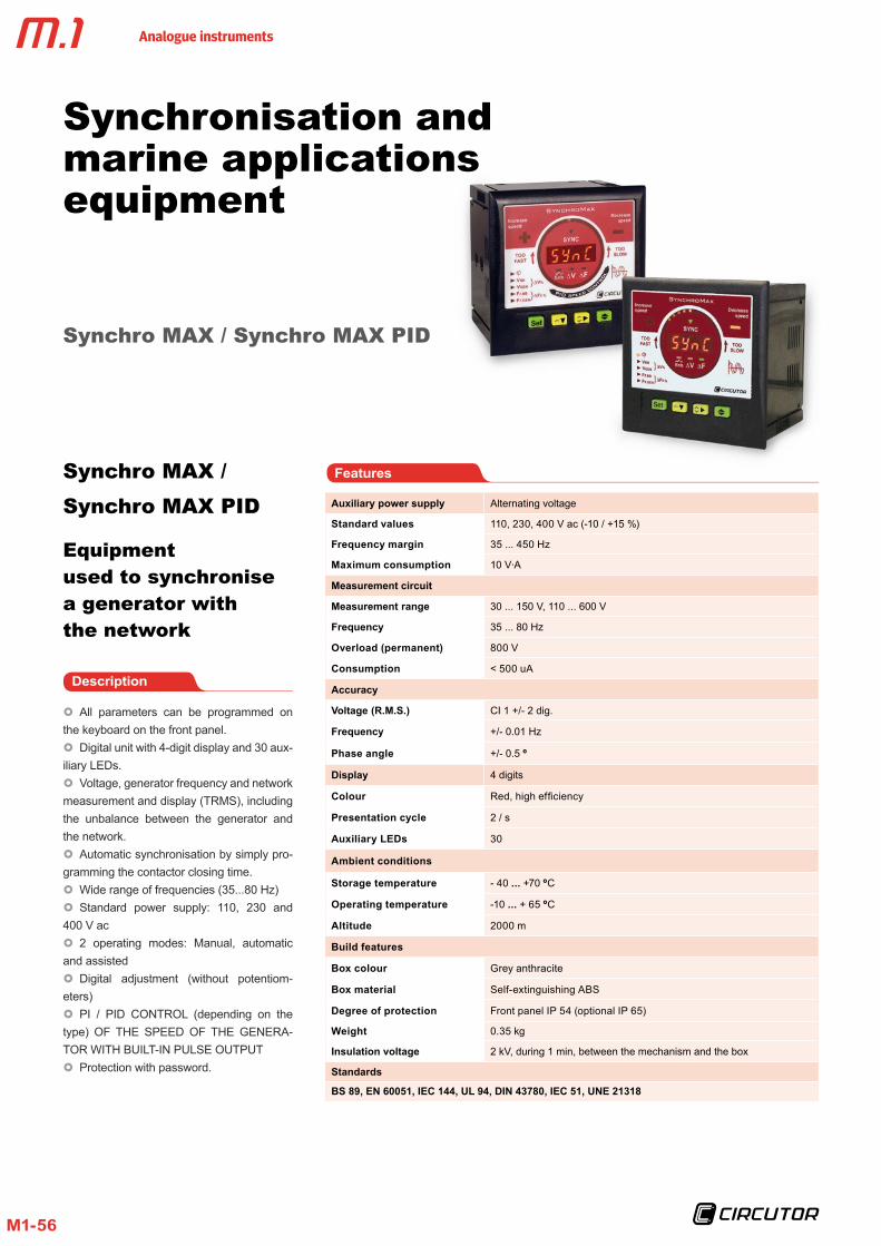
Analogue instruments
M1-56
Synchronisation and marine applications equipment
Synchro MAX / Synchro MAX PID
Description
All parameters can be programmed on the keyboard on the front panel. Digital unit with 4-digit display and 30 aux-
iliary LEDs. Voltage, generator frequency and network
measurement and display (TRMS), including the unbalance between the generator and the network. Automatic synchronisation by simply pro-
gramming the contactor closing time. Wide range of frequencies (35...80 Hz) Standard power supply: 110, 230 and
400 V ac 2 operating modes: Manual, automatic
and assisted Digital adjustment (without potentiom-
eters) PI / PID CONTROL (depending on the
type) OF THE SPEED OF THE GENERA-TOR WITH BUILT-IN PULSE OUTPUT Protection with password.
Features
Auxiliary power supply Alternating voltage
Standard values 110, 230, 400 V ac (-10 / +15 %)
Frequency margin 35 ... 450 Hz
Maximum consumption 10 V·A
Measurement circuit
Measurement range 30 ... 150 V, 110 ... 600 V
Frequency 35 ... 80 Hz
Overload (permanent) 800 V
Consumption < 500 uA
Accuracy
Voltage (R .M .S .) CI 1 +/- 2 dig.
Frequency +/- 0.01 Hz
Phase angle +/- 0.5 º
Display 4 digits
Colour Red, high efficiency
Presentation cycle 2 / s
Auxiliary LEDs 30
Ambient conditions
Storage temperature - 40 . . . +70 ºC
Operating temperature -10 . . . + 65 ºC
Altitude 2000 m
Build features
Box colour Grey anthracite
Box material Self-extinguishing ABS
Degree of protection Front panel IP 54 (optional IP 65)
Weight 0.35 kg
Insulation voltage 2 kV, during 1 min, between the mechanism and the box
Standards
BS 89, EN 60051, IEC 144, UL 94, DIN 43780, IEC 51, UNE 21318
Synchro MAX / Synchro MAX PID
Equipment used to synchronise a generator with the network

Analogue instruments
M1-57
Application
SynchroMax is a synchronism relay that has been designed to synchronise a generator with the network or with another generator used as reference. We can connect both in parallel in emergency or support applications when a greater power is needed.
Synchro MAX / Synchro MAX PIDSynchronisation and marine applications equipment
Unit's front panel
Low frequency
Enable
Measurements displayedPhaseMain voltage V BB
Generator voltage V GEN
Earth leakage voltage V %Main frequency Fr BB
Generator frequency Fr GEN
Frequency difference FR %
Voltage margin OK
Analogue simulationHigh frequency
4 digit indicator
Frequency margin OK
Description
CIRCUTOR has two types of synchronism relays: SYNCHRO MAX and SYNCHRO MAX PID.
Synchro Max Synchro Max is capable of adapting the gen-erator's frequency with an integrated PI regu-lation algorithm, in order to connect it in paral-lel to the electrical network. In addition, it can be used to measure and display the voltage, phase and frequency parameters of the gen-erator and network, as well as its differences.
Synchro Max PIDSynchro Max PID offers excellent stand-ard Synchro Max measurement, display and programming features, with a power-ful PID algorithm to control the generator's frequency.This type of control turns Synchro Max PID into a quick synchronisation device and, therefore, it offers the ideal solution to reduce synchronisation costs, since it minimises the time invested in such procedures.This type of control is perfect for small-scale
hydraulic power plants, among many other applications.Here is an example of how SYNCHRO MAX moves forward to a time tbrk (previously programmed by the user) to take into account the connection delay of the generator's contactor.
Tbrk: Contactor closing timetbrk: Time for closing the contact

Analogue instruments
M1-58
Synchro MAX / Synchro MAX PIDSynchronisation and marine applications equipment
Dimensions
SYNCROMAX
Connections
Coding table
Sync
hro
MA
X
M 1 X X X X 0 0 X
CodeInternal Code
Voltagepower supply
Standard (400 V) 0
110 V 1
230 V 2
References
Type SYNCHRO MAX SYNCHRO MAX PID
PID Control No Yes
Frequency 30 ... 70 Hz
Dimensions (mm)
a b c
9696
62,9
V measurement
30 . . . 150 M14624 M14634
110 . . . 600 M14625 M14635

Analogue instruments
M1-59
Insulation resistance meterMEG-1000
Application
MEG-1000 measures and controls the insu-lation resistance between phase and earth in a neutral insulated or impedance line (IT), with the use of relays. The insulation resist-ance can be displayed with a galvanometric indicator located on the front of the unit.
To carry out the measurements, the unit ap-plies a continuous voltage of 24 V between the phase and earth, measuring the leakage current circulating through the network insu-lation resistors. This current determines the insulation resistance.
The unit has two timed output relays, one acts as the maximum (triggered when the insulation resistance is lower than a deter-mined value). In both relays, the trip point and connection delay time can be adjusted with potentiometers located on the back of the unit.
When the insulation resistor is within the maximum and minimum values defined with the potentiometers, the NORMAL LED will be lit on the front panel. When the resistor is out of the margins defined, either exceeding or not reaching the normal levels, the ALARM LED will be lit on the front panel.
FeaturesDescription
Does not need an auxiliary power supply DIN box, with dimensions: 96x96 Class 1.5 Neutral insulated or impedance systems
(IT network)
Input circuit
Consumption 5 V·A
Frequency 20 ... 100 Hz
Overloads1.2 Un permanent
2 Un during 5 s
Accuracy 1.5 % FS
Ambient conditions
Operating temperature + 10 . . . +30 ºC
Limit temperature - 25 . . . + 40 ºC
Altitude 2000 m
Build features
Dimensions See the following table
Weight See the following table
Type of box panel
Terminal protection degree IP 00
Box protection degree IP 52
Weight 0.35 kg
Insulation voltage 2 kV, during 1 min, between the mechanism and the box
Standards
BS 89, EN 60051, IEC 144, UL 94, DIN 43780, IEC 51, UNE 21318
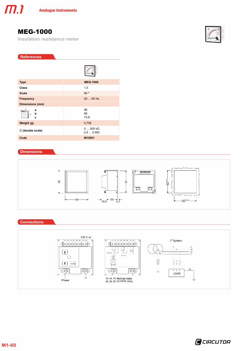
Analogue instruments
M1-60
Dimensions
MEG-1000Insulation resistance meter
References
Type MEG-1000
Class 1,5
Scale 90 º
Frequency 50 ... 60 Hz
Dimensions (mm)
a b c
969673,8
Weight (g) 0,708
Ω (double scale) 0 ... 500 kΩ0.5 ... 5 MΩ
Code M15051
Connections

Analogue instruments
M1-61
Hours run meterCH
Application
Timers are used to measure time with a simple, easy and reliable system. Measurement of start-up and operating
times. Modification and operating times. Production and quantity times. Data to provide information about the fo-
llowing:
FeaturesDescription
Input circuit
Current 10 mA
Frequency 50 or 60 Hz
Display Mechanical
Digits 1,5 x 3.5 mm with magnifier
Maximum value 99 999,99
Ambient conditions
Operating temperature +10 . . . +30 ºC
limit temperature -25 . . . +40 ºC
Type of box panel
Terminal protection degree IP 00
Box protection degree IP 52
Weight 0.35 kg
Insulation voltage 2 kV, during 1 min, between the mechanism and the box
Standards BS 89, EN 60051, IEC 144, UL 94, DIN 43780, IEC 51, UNE 21318

Analogue instruments
M1-62
Tim
er
M 1 X X X X 0 0 X X
CodeInternal Code
FrequencyStandard 50 Hz 0
60 Hz 1
Voltage
Standard (230 V) 024 V ac 6110 V ac 1
10..0.80 V dc 880...200 V dc A
References
CHHours run meter
Coding table
Dimensions Connections
CH 48
CH 72 / CH 96
Type a b c d e
72 mm 72 67,2 57,2 5,7 68+0,8
96 mm 96 91 57,2 5,7 92+0,8
Dimensions (mm)
CH 45
Type CH 48 CH 72 CH 96 CH 45
Class 1,5
Display 5 + 2 5 + 1
Dimensions (mm) a b c
484848
7272
62,9
9696
62,9
903655
Weight (g) 50 125 180 75
Code M14911 M14921 M14931 M14951
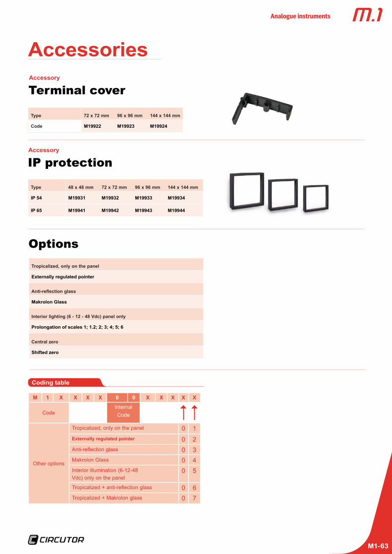
Analogue instruments
M1-63
Terminal coverAccessory
Type 72 x 72 mm 96 x 96 mm 144 x 144 mm
Code M19922 M19923 M19924
IP protectionAccessory
Type 48 x 48 mm 72 x 72 mm 96 x 96 mm 144 x 144 mm
IP 54 M19931 M19932 M19933 M19934
IP 65 M19941 M19942 M19943 M19944
OptionsTropicalized, only on the panel
Externally regulated pointer
Anti-reflection glass
Makrolon Glass
Interior lighting (6 - 12 - 48 Vdc) panel only
Prolongation of scales 1; 1 .2; 2; 3; 4; 5; 6
Central zero
Shifted zero
Coding table
M 1 X X X X 0 0 X X X X X
CodeInternal Code
Other options
Tropicalized, only on the panel 0 1Externally regulated pointer 0 2Anti-reflection glass 0 3Makrolon Glass 0 4Interior illumination (6-12-48 Vdc) only on the panel
0 5
Tropicalized + anti-reflection glass 0 6Tropicalized + Makrolon glass 0 7
Accessories

Analogue instruments
M1-64