Measure Guideline: Summary of Interior Ducts in New ... · of Interior Ducts in New Construction,...
46
Measure Guideline: Summary of Interior Ducts in New Construction, Including an Efficient, Affordable Method to Install Fur-Down Interior Ducts D. Beal, J. McIlvaine, K. Fonorow, and E. Martin BA-PIRC November 2011
Transcript of Measure Guideline: Summary of Interior Ducts in New ... · of Interior Ducts in New Construction,...
Measure Guideline: Summary of Interior Ducts in New Construction, Including an Efficient, Affordable Method to Install Fur-Down Interior Ducts D. Beal, J. McIlvaine, K. Fonorow, and E. Martin BA-PIRC
November 2011

i
NOTICE
This report was prepared as an account of work sponsored by an agency of the United States government. Neither the United States government nor any agency thereof, nor any of their employees, makes any warranty, express or implied, or assumes any legal liability or responsibility for the accuracy, completeness, or usefulness of any information, apparatus, product, or process disclosed, or represents that its use would not infringe privately owned rights. Reference herein to any specific commercial product, process, or service by trade name, trademark, manufacturer, or otherwise does not necessarily constitute or imply its endorsement, recommendation, or favoring by the United States government or any agency thereof. The views and opinions of authors expressed herein do not necessarily state or reflect those of the United States government or any agency thereof.
Available electronically at http://www.osti.gov/bridge
Available for a processing fee to U.S. Department of Energy and its contractors, in paper, from:
U.S. Department of Energy Office of Scientific and Technical Information
P.O. Box 62 Oak Ridge, TN 37831-0062
phone: 865.576.8401 fax: 865.576.5728
email: mailto:[email protected]
Available for sale to the public, in paper, from: U.S. Department of Commerce
National Technical Information Service 5285 Port Royal Road Springfield, VA 22161 phone: 800.553.6847
fax: 703.605.6900 email: [email protected]
online ordering: http://www.ntis.gov/ordering.htm
Printed on paper containing at least 50% wastepaper, including 20% postconsumer waste
i
Measure Guideline: Summary of Interior Ducts in New Construction, Including an Efficient, Affordable Method to Install Fur-Down Interior
Ducts
Prepared for:
Building America
Building Technologies Program
Office of Energy Efficiency and Renewable Energy
U.S. Department of Energy
Prepared by:
D. Beal, J. McIlvaine, K. Fonorow, E. Martin
BA-PIRC / Florida Solar Energy Center
1679 Clearlake Rd
Cocoa, Florida, 32922
NREL Technical Monitor: Stacey Rothgeb
Prepared under Subcontract No. KNDJ-0-40339-00
November 2011

ii
[This page left blank]

iii
Contents List of Figures ............................................................................................................................................. v List of Tables .............................................................................................................................................. vi Executive Summary ................................................................................................................................. viii 1 Introduction ........................................................................................................................................... 1
1.1 Purpose .................................................................................................................................1 1.2 Previous Publications ...........................................................................................................1 1.3 Definition of Interior Ducts .................................................................................................1 1.4 Styles of Interior Ducts ........................................................................................................1
1.4.1 Fur-up Chase ............................................................................................................1 1.4.2 Fur-down Chase .......................................................................................................2 1.4.3 Sealed Attic or Crawlspace ......................................................................................2
1.5 System Advantages and Disadvantages ...............................................................................3 1.5.1 Fur-up Chase ............................................................................................................4 1.5.2 Fur-down Chase .......................................................................................................5 1.5.3 Sealed Attic or Crawlspace ......................................................................................6
2 Document Inspections ......................................................................................................................... 7 2.1 Floor Plan Appropriate for Implementation ........................................................................7 2.2 Non-Energy Advantages ....................................................................................................10
2.2.1 Indoor Air Quality..................................................................................................10 2.2.2 Equipment Life ......................................................................................................10 2.2.3 Aesthetics ...............................................................................................................11 2.2.4 Occupant Comfort ..................................................................................................11
2.3 Risk Identification ..............................................................................................................11 2.3.1 Duct Leakage Overview ........................................................................................12 2.3.2 Assumption That Since the Chase is Sealed, the Ducts Can Be Leaky .................14 2.3.3 Trade Sequence and Interference ...........................................................................14 2.3.4 Code Issues ............................................................................................................14
3 Trade-offs ............................................................................................................................................ 15 3.1 Cost vs. Performance .........................................................................................................15 3.2 Cost and Issues for the Various Systems ...........................................................................15
3.2.1 Sealed Attic ............................................................................................................15 3.2.2 Sealed Crawlspace .................................................................................................18 3.2.3 Fur-up Chases ........................................................................................................19 3.2.4 Fur-down Chase .....................................................................................................19
3.3 System Interaction .............................................................................................................21 3.3.1 Effect of HVAC System Runtime ..........................................................................21 3.3.2 Return Pathways ....................................................................................................22 3.3.3 Trade Interactions ..................................................................................................22
4 Summary of Implementation of Various Methods ........................................................................... 22 4.1 Integrating the New Strategy Into Current Construction Processes ..................................22
4.1.1 Locate Chase ..........................................................................................................23 4.1.2 Before Construction of the Chase ..........................................................................23 4.1.3 General Chase Construction Guidelines ...............................................................25 4.1.4 Protecting the Chase After Completion .................................................................27

iv
4.2 Chase Design .....................................................................................................................28 4.2.1 Identify Chase Path ................................................................................................28 4.2.2 Involve All Subcontractors Whose Work May Impact the Chase Integrity ..........29
4.3 Field Inspection ..................................................................................................................29 4.3.1 Multiple to Daily, Inspections Needed ..................................................................29
4.4 Introduction of Detailed, Simplified and Inexpensive Method of a Fur-down Chase .......29 4.4.1 Install Ceiling/Chase Drywall ................................................................................30 4.4.2 Install Duct Work ...................................................................................................30 4.4.3 Finish Chase Construction .....................................................................................31 4.4.4 A Method to Reduce the Size of the Chase ...........................................................31 4.4.5 Transom Returns ....................................................................................................32
4.5 Verification ........................................................................................................................32 4.5.1 Blower Door Testing ..............................................................................................33 4.5.2 Duct Blaster Testing ..............................................................................................33 4.5.3 Room to Main Body Pressure Balancing ...............................................................33
References ................................................................................................................................................. 34 Acknowledgments .................................................................................................................................... 35

v
List of Figures Figure 1. Fur-up chase installed after rough framing. ............................................................................ 2Figure 2. Fur-down chase after rough framing. ....................................................................................... 2Figure 3. An unvented attic constructed by air sealing the roof deck with foam insulation. Note
how the attic duct is now within the home’s air and thermal barrier .............................................. 3Figure 4. A sealed crawlspace by air sealing the foundation walls with foam insulation. .................. 3Figure 5. Poorly insulated fur-up chase sides. ........................................................................................ 4Figure 6. Modified truss work necessitated by fur-up chase. ................................................................ 5Figure 7. Fur-up chase deliberately used for wiring runs. Also note the poor overall insulation of
the chase. .............................................................................................................................................. 5Figure 8. A fur-down chase used for architectural detail. ...................................................................... 5Figure 9. Air Handler Closet ....................................................................................................................... 8Figure 10. Fur-down chase in hallway. Note the restricted space for the chase due to the 8 ft
ceiling height. Note the space-saving, light gauge metal framing at the bottom of the chase. ... 9Figure 11. Free-standing chase in open area of floor plan. .................................................................. 10Figure 12. Air handler and duct system installed in a conventional attic. A relatively large volume
of air becomes trapped in the system between runtime events, and can encounter significant heat gain/loss to the point where it can cause comfort issues when introduced into the home’s interior. ................................................................................................................................................ 11
Figure 13. A jump duct through the attic. This will provide return air, over the interior wall. Note this is not an interior duct unless the attic is sealed. ..................................................................... 13
Figure 14. Transom return pathway, through the wall, over doorway of a master bedroom. ........... 13Figure 15. Fur-down chase above dropped ceiling. .............................................................................. 20Figure 16. Example of a perimeter chase. .............................................................................................. 20Figure 17. Free-hanging chase across an open space. Note separation of space accented by
chase. ................................................................................................................................................... 21Figure 18. Floor plan, showing the area to have a fur-down chase installed, highlighted in grey. .. 23Figure 19. Paint tags alerting crews to the location of the proposed chase. ..................................... 24Figure 20. Supply duct location marked in the side of a fur-down chase. .......................................... 24Figure 21. Air handler closet ceiling sealed with duct board. .............................................................. 25Figure 22. Duct work strapped in place prior to finishing the framing of the chase. ........................ 26Figure 23. Finish framing for chase. ....................................................................................................... 26Figure 24. Air-sealing a fur-up chase. ..................................................................................................... 26Figure 25. Chase side wall supply sealing detail. .................................................................................. 27Figure 26. Ceiling drywall installed at fur-down chase top. Drywall is slid through a ¾”+ gap
between the wall top plate and the truss bottom chord, ensuring a good air barrier. ................ 30Figure 27. Duct work hung with 2” strapping after chase ceiling drywall installed and sealed. ...... 31Figure 28. Chase sides and bottom installed. ........................................................................................ 31Figure 29-31. (Left to right) Connecting flex duct to a trunk line for a supply run-out results in a
wide chase. Instead, a supply outlet constructed from a duct board box can be directly affixed to the trunk. This permits construction of a much narrower chase. ............................................ 32
Unless otherwise noted, all figures were created by the BA-PIRC team.

vi
List of Tables Table 1. Impact of roof pitch on volume and heat transfer area. ......................................................... 17Table 2. Cost comparison of two interior duct methods for differing roof pitch, Partner 1. ............. 17Table 3. Cost Comparison of two interior duct methods, Partner 2. ................................................... 18 Unless otherwise noted, all tables were created by the BA-PIRC team.

vii
Definitions A/C Air Conditioning ACCA Air Conditioning Contractors of America AH Air Handler FSEC Florida Solar Energy Center HUD Housing and Urban Development HVAC Heating, Ventilation, and Air Conditioning IAQ Indoor Air Quality IECC International Energy Conservation Code Manual D ACCA Manual for Residential Duct Systems Manual J ACCA Manual for Residential Load Calculation MHLab Manufactured Housing Lab RBS Radiant Barrier System RH Relative Humidity SEER Seasonal Energy Efficiency Ratio VOC Volatile Organic Compound

viii
Executive Summary
This document illustrates guidelines for the efficient installation of interior duct systems in new housing. Interior ducts result from bringing the duct work inside a home’s thermal and air barrier. Architects, designers, builders, and new home buyers should thoroughly investigate any opportunity for energy savings that is as easy to implement during construction, such as the opportunity to construct interior duct work. In addition to enhanced energy efficiency, interior ductwork results in other important advantages, such as improved indoor air quality, increased system durability and increased homeowner comfort.
While the advantages of well-designed and constructed interior duct systems are recognized, the implementation of this approach has not gained a significant market acceptance. This guideline describes a variety of methods to create interior ducts including the fur-up chase method, the fur-down chase method, and interior ducts positioned in sealed attics or sealed crawl spaces.
As communication of the intent of an interior duct system, and collaboration on its construction are paramount to success, this guideline details the critical design, planning, construction, inspection, and verification steps that must be taken. Involved in this process are individuals from the design team; sales/marketing team; and mechanical, insulation, plumbing, electrical, framing, drywall and solar contractors.

1
1 Introduction
1.1 Purpose This document illustrates guidelines for the efficient installation of interior duct systems in new housing. Architects, designers, builders, and new home buyers should thoroughly investigate any opportunity for energy savings that is as easy to implement during construction as implementing interior duct work. In addition to enhanced energy efficiency, interior ductwork results in other important advantages, such as improved indoor air quality, increased system durability, and increased homeowner comfort.
While the advantages of well-designed and constructed interior duct systems are recognized, the implementation of this approach has not gained a significant market acceptance. Homes in hot climates are still typically designed and built with duct systems in the attic. This guideline describes a variety of methods to create interior ducts, including a cost-effective method used by four builders in the Gainesville, FL, area to construct interior ducts in more than twelve site-built homes.
1.2 Previous Publications This guideline summarizes two previous peer-reviewed Florida Solar Energy Center (FSEC) papers:
Fonorow, K., Jenkins, D., Thomas-Rees, S., and Chandra, S. “Low Cost Interior Duct Systems for High Performance Homes in Hot Climates”, ACEEE Summer Study on Energy Efficiency in Buildings, August 15-20, 2010, in Pacific Grove, CA.
McIlvaine, J, Beal, D., and Fairey, P. “Design and Construction of Interior Duct System” Florida Solar Energy Center FSEC-PF-365-01, April 2001, Revised July 2002, Presented at the Affordable Comfort Conference 2001, April 30-May 5, 2001, Milwaukee, WI.
1.3 Definition of Interior Ducts Duct work is used to transport conditioned air to and from occupied rooms. Typically, this duct work is in unconditioned space, such as the attic or crawlspace. Interior ducts result from bringing the duct work inside a home’s thermal and air barrier. This concept involves positioning the entire forced air system, including the air handler, within the conditioned space—particularly within the air and thermal boundary. The primary challenges of this approach involve establishing an air barrier around the ducts and integrating the new detail into the design and construction process.
1.4 Styles of Interior Ducts 1.4.1 Fur-up Chase A modified truss system can create a space for a sealed and insulated duct chase above the ceiling. Observed from the living area, the fur-up chases are hidden by the finished ceiling, whereas from the attic, they appear as a boxed out area covered with insulation (Figure 1).

2
Figure 1. Fur-up chase installed after rough framing.
1.4.2 Fur-down Chase A fur-down chase of framed soffits creates space for ducts to be installed below the ceiling. Chases furred-down into the conditioned space generally occupy the upper portion of hallways, run along walls, and/or cut across open living areas as architectural elements (Figure 2).
Figure 2. Fur-down chase after rough framing.
1.4.3 Sealed Attic or Crawlspace A sealed space for ducts can be created by moving the air and thermal barrier to the exterior plane of the attic or crawlspace. Relocating the thermal and air barriers of the house to the outer

3
edges of the structure creates either an insulated roof deck (Figure 3) or foundation walls (Figure 4). The space containing the ducts is not vented to the outside and is often conditioned. This quasi-conditioned space, within the home’s air and thermal barrier, can be a good location for a duct system.
Figure 3. An unvented attic constructed by air sealing the roof deck with foam insulation. Note
how the attic duct is now within the home’s air and thermal barrier
Figure 4. A sealed crawlspace by air sealing the foundation walls with foam insulation.
1.5 System Advantages and Disadvantages Interior duct work can curtail or eliminate some of the negative effects of duct leakage. Benefits include energy savings, improved indoor air quality, and increased system life. A significant body of literature exists to support the implementation of interior duct systems. An excellent literature review of the subject and demonstration of interior ducts for site built production housing in the Pacific Northwest is available (Lubliner, Kerr, Gordon, and Murray 2008). In this marine climate, simulations show that compared to base case leaky ducts, interior ducts can save between 9% and 28% in heating energy costs and between 8% and 17% in cooling energy costs (Hales and Baylon 2010). For manufactured housing in hot humid climates, prototype homes with interior ducts were built by two manufacturers, and experiments were conducted to determine savings, which yielded up to 20% savings (Moyer, N., Stroer, D., Hoak, D., McIlvaine, J., and Chandra, S., 2008). Changing from sealed ducts in a vented attic to an interior fur-down system resulted in cooling energy savings of 17% for a SEER 21 HVAC and 11% for a SEER 13 HVAC. These results were determined in controlled experiments using a 1,600 sq. ft. HUD-code manufactured home research facility at the Florida Solar Energy Center facilities in Cocoa, FL, and is also discussed later in this guideline (Cummings and Withers. 2010).

4
On the other hand, interior duct implementation requires a greater degree of trade coordination, which can be difficult to facilitate. This coordination is best accomplished by a site meeting after house dry-in. This meeting should include the designer, sales/marketing professionals, and mechanical, insulation, plumbing, electrical, framing, drywall and solar contractors. Oversight duties are increased for the site supervisor. A quality installation is difficult to establish and maintain throughout the construction process.
There can be additional costs for materials, such as foam insulation, custom trusses for a fur-up installation, or additional framing and drywall. A more expensive duct system (duct-board versus flex-duct) may be required due to space limitations.
Payback is impacted by other efficiency improvements, often to the point of negative cash flow, depending on the expense of the method employed. Therefore, cost benefits are seldom the sole motivation for implementation.
1.5.1 Fur-up Chase Fur-up chases are hidden from view once the home is built and the attic is insulated. As a result, duct size and ceiling heights are less of an issue than encountered in fur-down chases.
A fur-up chase is a kneewall into the attic, and must be insulated like a kneewall. The sides of the chase are difficult to insulate (Figure 5), and damage may not be easy to detect. In addition, any misstep in the attic can result in future damage to the structure. If trusses are used, a new truss package is needed (Figure 6). Since fur-ups are more obvious from the attic than fur-downs, they are more likely to be targeted for wiring and plumbing runs, compromising the required air and thermal barrier (Figure 7). Overall, the chase needs to be carefully inspected before the builder releases the house.
Figure 5. Poorly insulated fur-up chase sides.

5
Figure 6. Modified truss work necessitated by fur-up chase.
Figure 7. Fur-up chase deliberately used for wiring runs. Also note the poor overall insulation of
the chase.
1.5.2 Fur-down Chase Fur-down chases are more visible than fur-up chases, and can add architectural detail. By inserting dropped soffits in strategic areas, one can define the character of the interior spaces (Figure 8).
Figure 8. A fur-down chase used for architectural detail.
Multiple job site visits from the framers and the drywall crew are often required when building the chase. Due to size limitations, fur-down chases often need rigid ductboard duct; flex duct often results in a chase that is too large to maintain aesthetics. Ceiling heights cannot be less than

6
7'0" to meet code and allow for door framing. For homes with 8' ceilings, that allows 12"or less for the ducts and the structure of the chase. This type of duct system also limits register size and placement.
1.5.3 Sealed Attic or Crawlspace A sealed attic or crawlspace is very easy to implement in new construction, often no more than a specification change and a new subcontractor. If installed correctly, quality spray foam installations easily maintain the integrity of the air barrier and thermal barrier. They also provide for a very airtight attic or crawlspace. The purpose of foam insulation is usually evident, and its location is often far from other trades’ work areas. As a result, there is less post-installation damage, and small breaches can easily be repaired with canned foam.
However, foam is significantly more expensive than conventional insulation products, which, in combination with thickness limitations of the applied foam, often leads to lower R-value installations than found with conventional insulation. When insulating a roof deck, due to the roof’s pitch, there is more area to be insulated than if the insulation is conventionally located at the attic floor.
In foam installations. the ceiling drywall (or crawlspace ceiling) is not typically insulated (R-value of drywall less than 0.5, versus a typical attic floor of R-19 or more). This space’s temperature needs to be kept within a few degrees of the interior space. If the sealed attic is unconditioned, the temperature differences between the attic and the living spaces will rise, resulting in massive heat flux into the house (a 1° temperature difference across drywall(R -0.5) is equivalent to a 38° temperature difference or more across an R-19 ceiling), defeating the effort of sealing the attic to save energy. Typical methods of keeping the sealed attic cool include supply and return ducts in the space, or registers installed in the chase to allow room air to passively enter the chase.
In crawlspaces, the difficulty is less temperature-related and more moisture-related. If a sealed crawlspace is adopted and conditioned, great care must be taken to provide a long-lasting seal. The effect of workmen crawling on 6-mil poly ground cover products is usually a rip, ruining the moisture barrier that the system is relying on. In hot-humid climates, humidity levels can quickly build up in a crawlspace with a poorly sealed floor (Beal and Chasar, 2006). In these and other poorly carried out crawlspace sealing efforts where conditioned supply (and return) air is ducted to the crawlspace, very poor indoor air quality in the house can result. If contemplating a sealed crawlspace, consider a more substantial floor covering. There are products available that more resemble a pool liner than 6-mil poly, and should provide a long lasting seal. A concrete “rat slab” for the floor of the crawlspace would be ideal. Sealing around any piers and pipes in the crawlspace is also challenging, and care must be taken to insure a thorough job.
Building code officials are now beginning to recognize the validity of sealing attics and crawlspaces, but the local authority should be consulted to ensure that no code issues arise with a sealed attic or crawlspace. Be especially attentive to fire codes, as foam is unlikely to meet fire resistance standards, often requiring sealing with a second coating, or encapsulation in drywall to provide the necessary fire resistance rating. A sealed crawlspace is not a viable option in areas where heavy flooding is a concern.

7
2 Document Inspections
2.1 Floor Plan Appropriate for Implementation Let the guiding principal for building an interior duct system be the establishment and maintenance of an air barrier between the duct system and the exterior of the building. After an air barrier is established, a thermal barrier in the same location is needed.
In situations where a sealed attic or crawlspace is selected, the floor plan is not a significant factor in the implementation of interior ducts as this construction detail is amenable to most floor plans. These sealed assemblies allow the duct system to be installed as it typically would be, but the system benefits from being “interior” by virtue of the new location for the air and thermal barrier.
In ranch-style homes (homes with all bedrooms grouped together at one end of the house and incorporating a main hallway), a chase can run the length of the hallway (flanked by bedrooms) and extend out into the main living area. In split-plan homes (homes with bedrooms on either end of the house and separated by the main living area) a duct chase can run from the master bedroom area, across the main living area, and into the other bedrooms. Whereas the hallway fur-down makes use of the upper portion of the hall walls (Figure 10), chases in open areas are built out from one wall and down from the ceiling framing (Figure 8), or are free-standing chases built down from the ceiling (Figure 11).
Prior to committing to an interior duct system with a chase, a sizing calculation must be performed to ensure the chase can accommodate large enough ducts to deliver the required air. Space issues can occur in houses with an 8’ ceiling height. With information derived from the HVAC designers’ ACCA Manual J and D calculations, the home designer can finalize plans that consider the size requirements and path of the distribution system.
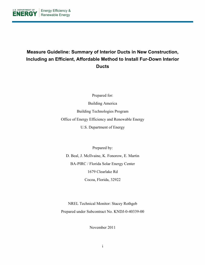
The air handler can be located either centrally or at one end of the chase, but as the heart of the duct system, it must be inside the conditioned space. Unless a sealed attic or crawlspace will be the air handler’s home, this requires the construction of an air handler closet (Figure 9). Building America researchers have found that the idea of a sealed air handler closet is not often understood (McIlvaine, Beal and Chandra, 2009). In hot-humid climates where gas heating is used, the inexpensive, naturally aspirated furnace unit is often placed in an interior closet, and combustion make-up air is provided by leaving the ceiling of the air handler closet open to the attic. This practice carries over into heat pump or A/C combined with strip heat installations, as it has become a regional standard practice. This has obvious impacts on the houses’ air and thermal barriers and must be dealt with prior to contemplating an interior duct system. The following is an implementation Checklist for Moving AHU from the Attic to an Interior Closet: Develop closet design with mechanical contractor
o Revise Manual J and Manual D calculations o Size return opening per Manual D calculations o 8” recommended clearance on all sides of air handler to improve accessibility o Condensate location may need to be moved
Integrate closet design with floor plan o Reflect changes on mechanical, electrical, and plumbing plans o Truss design and layout must accommodate supply plenum
8
o Provide closet elevations as needed Show return grill rough opening dimensions Indicate filter location Locate thermostat, condensate drain line path Locate outside air ventilation duct and damper
o Provide section of closet to explain construction Show drywall (green board ok) lining for entire closet including ceiling Show framing details for AHU platform – constructed inside drywall
lining Show blocking for return air grill Indicate air sealing points
• Seal all edges and seams in drywall lining with code-approved sealant – recommended materials include drywall mud, mastic, fire rated caulk, and fire rated foam
• Seal around supply plenum • Seal between all framing members in rough opening for return grill • Seal all wiring and plumbing penetrations through the drywall and
AHU platform Develop quality assurance checklist for interior AHU closet Call subcontractor attention to new details
o All changes should be reflected in construction documents, specifications, and emphasized in a cover letter
o With slab-on-grade floors, plumber must install condensate drain line before slab is poured
Provide materials (drywall and sealant) for roughing out and finishing closet prior to mechanical rough-in
Complete quality assurance checklist for interior AHU closet prior to mechanical rough-in
Figure 9. Air Handler Closet

9
To locate a fur-up or fur-down chase in a specific design, start by examining the plan for an obvious path. To avoid long run-out ducts, the chase should trace a path down the center of the house and go to all spaces to be served. Otherwise, small supply runs in unconditioned spaces or excessive chase construction will be required to reach distant rooms. Align the central chase with closets, cabinets, or transverse halls to achieve coverage of all rooms.
As in all duct systems, adequate return ducting must be provided. To avoid an entire extra chase, ducted returns are not recommended. A passive system using transfer ducts of some type is preferred. For a guide on duct sizing, including return ducts, transfer ducts and supply ducts, please find Building Science Corporation’s Information Sheet at: http://www.buildingscience.com/documents/information-sheets/information-sheet-transfer-grilles-and-ducts. This Information sheet is linked to several other documents that go into great detail about duct sizing and its ramifications. A very crude, but effective, rule of thumb for passive return sizing (a central return with passive returns from each room, as opposed to a fully ducted return) is to allow 1.5 times the return area as the total supply area. Often it is tempting to use the chase as a “ducted” return to the air handler, as the chase goes to all rooms. This practice is not currently recommended because reliable sealing of the chase from surrounding unconditioned spaces has proven difficult to achieve. Any leakage in the chase air barrier can cause severe return leaks. This is similar to the difficulties found with using building cavities as ducts, such as panned floor joists. Additionally, even if the chase is properly sealed from the surrounding unconditioned space, the chase would need to be significantly larger to accommodate the necessary return air flow.
Figure 10. Fur-down chase in hallway. Note the restricted space for the chase due to the 8 ft ceiling height. Note the space-saving, light gauge metal framing at the bottom of the chase.

10
Figure 11. Free-standing chase in open area of floor plan.
Be sure that the mechanical contractor takes the location of the ducts into consideration for system sizing calculations and the size of the chase (less than 12" clearance for 8' ceilings) (Figure 10) for duct sizing calculations. The duct design should incorporate sizing and design considerations to allow adequate air distribution into all rooms. Fur-down chase systems are difficult to use with a perimeter duct installation, as the chase typically runs down the center of the building for ease of construction.
The top of a fur-down chase should be uninterrupted by framing. Miscellaneous bracing that interrupts the upper air barrier creates additional cutting, fitting, and sealing work. In most cases, the air barrier will be made of an air-tight material (e.g. drywall, rigid insulation) sealed at the edges and seams, and the thermal barrier will consist of ceiling insulation installed over the top of the chase plus the insulated sides for fur-ups.
Though floor cavities between upstairs and downstairs are often thought of as being in conditioned space, it is rarely the case. The floor cavity is often not bound by a definitive air barrier. However, with careful attention to sealing and insulating the perimeter of the floor cavity, ducts in floor cavities can be a viable interior duct option. Historically, the EPA ENERGY STAR for New Homes Program has mandated sealing the band joist between floors.
2.2 Non-Energy Advantages 2.2.1 Indoor Air Quality IAQ is improved by eliminating duct leakage. Unconditioned areas, such as attics and crawlspaces, harbor dirt and allergens which duct leakage can force into the conditioned space, either through duct leakage or via pressure imbalances caused by inadequate return pathways. A properly executed interior duct system eliminates duct leakage and its related infiltration and exfiltration problems.
2.2.2 Equipment Life Equipment life will be improved by eliminating the dirt, contamination, moisture and heat the system is exposed to in unconditioned attics and crawlspaces. Component life is increased by removing equipment from areas of excessive thermal excursions, dirt, and moisture.

11
2.2.3 Aesthetics A fur-down chase has the potential for enhancing home aesthetics by adding architectural interest and defining interior spaces (Figure 11). A sealed attic or crawlspace can provide an alternate “interior” location for the air handler (and water heater), which in turn, increases usable floor space in the home.
2.2.4 Occupant Comfort An interior duct system can improve occupant comfort by eliminating pulses of hot/cold air upon equipment start. In cases where the duct systems, and sometimes the air handler, are located in an extreme environment such as a hot or cold vented attic or crawlspace, the air initially delivered into the conditioned space on equipment start can be uncomfortably cold or warm (Figure 12).
Figure 12. Air handler and duct system installed in a conventional attic. A relatively large volume of air becomes trapped in the system between runtime events, and can encounter significant heat gain/loss to the point where it can cause comfort issues when introduced into the home’s interior.
2.3 Risk Identification Once the decision is made to build an interior duct system the builder must make a clear and consistent commitment. Then, this commitment must be communicated to all of the relevant trades and all involved parties (trades, designers, architects, etc.) must be dedicated to this task. Two critical trades are the home and HVAC design professionals. The best opportunity to minimize costs while ensuring an aesthetically pleasing outcome is during the preliminary schematic design phase of the home. Failures here will likely result in a poorly implemented end product.
An interior duct system should be planned during a home’s design stage, prior to interior framing, since it would be difficult, but not impossible, to implement after this stage. An interior duct system is not often suitable for retrofit unless a sealed attic or crawlspace is created.

12
2.3.1 Duct Leakage Overview Conventional forced air heating and cooling systems employ an air distribution system that includes an air handler and a duct system. The air handler is designed to remove air from the house, condition it, and supply it back to each room.
Duct leakage can occur on either the supply side or the return side of the air handler, as well as in the air handler itself. Both supply and return leaks cause air to move in unplanned, unpredictable ways, usually through unconditioned spaces and often bypassing air, thermal, and moisture barriers, as well as air filtration systems.
2.3.1.1 Supply Leak When supply ducts are located outside the home’s air barrier leak, they create a negative pressure within a house because more air is being removed from the interior than is being supplied back to the interior. This negative pressure results in air being drawn from outside and/or unconditioned spaces (uncontrolled infiltration) through holes in the home’s air barrier potentially leading to:
• Back drafting of atmospheric combustion devices • Introduction of outside air pollution, pollen, and other allergens • Introduction of airborne particles (dust, insulation, building material particles) from floor,
wall, ceiling cavities • Degraded comfort (temperature, humidity) • Greater space conditioning load • Reduced system life.
Supply leaks also spill conditioned air into unconditioned spaces, wasting energy and creating the potential for mold growth, condensation, and rot.
2.3.1.2 Return Leak When return ducts leak, part of the return air is drawn from the outside or unconditioned spaces instead of the interior. This air can be dirty, and it often bypasses the system’s filter. The leakage creates a positive pressure in the house because more air is being supplied than is being removed. The positive pressure forces air through holes in the home’s air barrier (uncontrolled exfiltration). Return duct leakage leads to:
• Lowered heating and cooling capacity with degraded comfort. • Introduction of outside and/or unconditioned air into the air handler, with its attendant
moisture, dirt, and pollutants. • Increased conditioning load • Reduced system life.
2.3.1.3 Inadequate Return Paths In rooms that can be isolated from a central return by door closure (bedrooms, studies, bonus rooms, etc.), a return pathway for the supply air must be provided. An inadequately returned room accumulates internal pressure when the door is closed during air handler operation. In turn, the main body of the house is placed under negative pressure. These pressure differences exist even if the duct system is leak-free. The pressure excursions seen are further exacerbated by tight construction techniques that reduce infiltration/exfiltration paths. For sizing guidance, please

13
refer to Building Science Corporation’s Information Sheet at: http://www.buildingscience.com/documents/information-sheets/information-sheet-transfer-grilles-and-ducts. This Information sheet is linked to several other documents that go into great detail about duct sizing and its ramifications
Adequate return pathways must be provided to all occupied rooms where doors may be closed for extended periods of time. Door undercutting and other crude methods rarely provide adequate area to accommodate the amount of supply air. A ducted return system must be carefully sized to avoid pressure imbalances due to mismatched flow rates. For a ducted return to be considered an interior duct system, it needs to be in a chase, or a sealed attic or crawlspace. For these reasons, a passive return system with jump ducts (Figure 13), transoms (Figure 14), or through-the-wall transfers combined with a central return are recommended. A crude sizing rule-of-thumb for passive returns is to allow 1.5 times the net free area of return as supply.
Figure 13. A jump duct through the attic. This will provide return air, over the interior wall. Note
this is not an interior duct unless the attic is sealed.
Figure 14. Transom return pathway, through the wall, over doorway of a master bedroom.
2.3.1.4 Total Duct and Duct Leakage to the Outside Duct leakage can occur anywhere in a duct system. Leakage that remains in the conditioned space, for instance leakage around registers poorly sealed to the wall or ceiling, or leakage from

14
an air handler installed in an interior air handler closet, is known as leakage to the inside. Of significant concern is the duct leakage that results in air leaking to or from areas outside of the conditioned space, which is known as leakage to the outside.
Typical home energy audits should make two measurements of duct leakage: 1) total leakage, which includes both leakage to the inside and outside and 2) leakage to the outside, a measurement that excludes the leakage to the inside. Correctly installing ducts in the interior of the building should eliminate duct leakage to the outside.
2.3.2 Assumption That Since the Chase is Sealed, the Ducts Can Be Leaky The authors and the builder partners of this study agree that it is easier to create an air tight duct system than it is to create an airtight chase. They also agree that it would be a mistake to assume that tight duct systems are not needed when the ducts are placed in an interior chase. Leaky ducts placed in leaky chases will not provide the desired energy or health benefits; whereas, an airtight duct system in a leaky chase still derives some of the energy benefits of interior ductwork without causing the building durability and health problems typically associated with leaking duct work. As it is very hard to insure that the chase will be isolated from ambient conditions, insulated duct work should still be used to avoid any condensation potential from humid air entering the chase.
2.3.3 Trade Sequence and Interference Installation of a fur-up/down chase will alter the order of trades on the job. As a result, carpentry and drywall workers must construct the chase prior to their normal schedule.
Often the proposed location of the chase is likely to interfere with other trades. Therefore, the chase location should be identified prior to construction to avoid interference. Typical problems arise when other trades viewing the chase fail to understand its purpose and use the space for their wire (electrician, phone, and cable/alarm installers) or pipes (plumbers and the HVAC contractor). Hence, it is important to protect the chase from other contractors who may want to use it as a convenient run. Otherwise, the resulting holes will compromise the air barrier and defeat the intent of the chase.
Communication is an important factor in preventing this issue. Advisory notices to cable, security, and phone installers should be posted in conspicuous locations such as the panel box, attic access hatch, wiring service entrance, etc. Since these notices cannot clearly identify the location of the air boundary, they should advise the installer to seal any penetrations to drywall made from unconditioned spaces. Though it should be standard practice, and is often required by code, virtually all services that are installed post-occupancy are never inspected.
2.3.4 Code Issues The 2009 International Energy Conservation Code (IECC) recognizes sealed crawlspaces (402.2.9) and attics (402.2.2), but not all municipalities have adopted this (or any) energy code. If contemplating a sealed crawlspace, ensure that there is no flooding issue in the location selected, as flood concerns are of higher importance than energy concerns. Sealed attics can also present code issues, especially due to fire codes. If the attic or crawlspace is defined as conditioned space (or, in some cases, merely served by supply and returns) the foam may have to comply with NFPA 2009 12.5.5.3 requirements for fire resistance, combustibility, and smoke

15
release standards (NFPA 286, ANSI/UL 1715 and 1040, and FM4880 are test standards to look for). Sealed attics have the potential to increase the conditioned square footage of the house, therefore affecting its tax base. Failure to pre-approve the design features desired can result in slow permitting and failed inspections. Ultimately, it can result in abandonment of the attempt due to lack of communication with local officials. It is typically more difficult to beg forgiveness from code officials than to seek approval prior to construction.
Ceiling height can be a code issue with fur-down chases, mainly in houses with 8’ ceilings. Minimum duct sizes can challenge the typical 7’ ceiling height code requirement. To minimize the space needed for the chase structure, detail the smallest available framing member that will support the weight of the drywall (for the bottom of chase) and ducts (if not supported by straps). This might be 2 x 2s or light gauge metal framing (Figure 10).
3 Trade-offs
After opting for an interior duct system, the next decision is to determine which method will be pursued. The implementation methods are either via chase constructions, or sealed attic/crawlspace systems.
3.1 Cost vs. Performance The initial cost of an interior duct system is somewhat fixed by the floor plan of the home. However, although interior duct work can lead to energy savings, the magnitude of the resulting energy savings from this measure is affected by the home’s heating/cooling load. As the home becomes more energy efficient through envelope or other improvements that reduce heat gain/loss, the cooling and heating portion of the home’s energy consumption drop proportionally. Therefore, for a given floor plan, the payback period to recoup the added cost of the interior duct system is dependent on the overall efficiency of the home. As the home’s other systems become more efficient, an interior duct system becomes less financially appealing.
Higher efficiency, multi-capacity HVAC units may operate for nearly twice as many hours per day as single-capacity systems. Conductive and air leakage losses of the duct system can have a greater impact on these types of systems because conditioned air remains in the ductwork for longer periods of time.
3.2 Cost and Issues for the Various Systems 3.2.1 Sealed Attic Sealed attics constructed with a spray foam are easy to implement, easy to inspect, and fairly obvious in their function. For attic installations, the roof deck and soffit area needs to be sealed to provide the “interior” space for the ducts (and sometimes air handler). Sealed attics and crawlspaces also provide more desirable areas for storage than their vented counterparts. Additional framing and air barrier material is often needed to separate the attic over the living space from the attic over garages and porches.
In foam installations the ceiling drywall (or crawlspace ceiling) is not typically insulated (R-value of drywall less than 0.5, versus a typical attic floor of R-19 or more). This space’s temperature needs to be kept within a few degrees of the interior space. If the sealed attic is

16
unconditioned, the temperature differences between the attic and the living spaces will rise, resulting in massive heat flux into the house (a 1° temperature difference across drywall (R -0.5) is equivalent to a 38° temperature difference or more across an R-19 ceiling), defeating the effort of sealing the attic to save energy. Typical methods of keeping the sealed attic cool include supply and return ducts in the space, or registers installed in the chase to allow room air to passively enter the chase.
If the attic or crawlspace is defined as conditioned space (or, in some cases, merely served by supply and returns) the foam may have to comply with NFPA 2009 12.5.5.3 requirements for fire-resistance, combustibility, and smoke release standards (NFPA 286, ANSI/UL 1715 and 1040, and FM4880 are test standards to look for).
Currently, foam products are significantly more expensive than conventional blown insulation products. This cost difference is further exaggerated by the roof’s pitch. The steeper the roof’s pitch, the larger the area that must be insulated. Further, this increased surface area is now the thermal barrier, resulting in a larger heat transfer area between the conditioned space and the ambient.
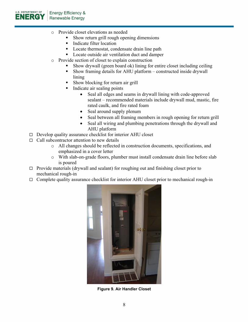
These factors are quantified in Table 1. One of the builder partners in this research builds a 5000 ft2 house with 10’ ceilings. This partner implemented interior ducts both through a fur-down chase (technique outlined in section 4) and through sealed attics. The impact of roof pitch on conditioned volume and heat transfer area becomes significantly noticeable when examining these houses. Homes with two different roof pitches, 9 in 12 and 4 in 12, each with 5000 ft2 of interior floor space and 10’ ceilings, are illustrated in the following table.
Important Definitions Interior Ducts: Involves positioning the entire forced air
system, including the air handler, within the conditioned space - particularly within the air and thermal boundary.
Fur-up Chase: Space for a sealed and insulated duct chase above the ceiling; it is hidden from view once the home is built and the attic is insulated. These systems often involve modified truss systems to accommodate the chase.
Fur-down Chase: Creates space for ducts to be installed below the ceiling and generally occupies the upper portion of hallways and/or cuts across open living areas, etc. as architectural elements.
Sealed Attic or Crawlspace: Created by moving the air and thermal barrier to the exterior plane of the attic or crawlspace. The space containing the ducts is not vented to the outside and is often conditioned. Easy to implement in new construction.
Duct Leakage: Can occur on either the supply side or the return side of the air handler, and in the air handler itself. Supply and return leaks cause air to move through unconditioned spaces and bypass air, thermal, and moisture barriers.
Supply Leak: Spills conditioned air into unconditioned spaces, wasting energy and creating the potential for mold growth, condensation, and rot. When supply ducts are located outside the home’s air barrier, negative pressure can draw outdoor air inside a house.
Return Leak: When return ducts leak, part of the return air is drawn from the outside or unconditioned spaces instead of the interior. Return duct leakage leads to: reduced heating and cooling capacity with degraded comfort; introduction of outside and/or unconditioned air into the air handler, with its attendant moisture, dirt, and pollutants, increased conditioning load, and reduced system life.
Blower Door Testing: Involves depressurizing the house to a standard pressure with respect to the outside, usually 50 Pascals. Depending on the pressure size, a determination can be made regarding the integrity of the interior duct system.
Duct Blaster Testing: Two tests can be performed with the duct blaster, one that measures the leakage of the entire duct system—both into the interior and exterior of the house, and a second test that measures the duct leakage to the exterior of the building only.
17
Table 1. Impact of roof pitch on volume and heat transfer area.
Parameter Unvented Attic 9:12
Roof
Interior Ducts 9:12
Roof
Unvented Attic 4:12
Roof
Interior Ducts 4:12
Roof Floor Area (ft2) 5,000 5,000 5,000 5,000 House Volume (ft3) 50,000 50,000 50,000 50,000 Roof Pitch (Rise/run) 9/12 9/12 4/12 4/12 Additional Volume (ft3) 37,000 0 16,500 0 Heat Transfer Area (ft2) 7,800 5,000 5,270 5,000
Material cost is an additional concern. For the same builder and house plan as shown in Table 1, Table 2 shows the cost breakdown for a sealed attic created via a spray foam roof deck versus using radiant barrier sheathing (RBS) decking, and conventional R-38 attic insulation combined with interior duct work via a fur-down chase. Quotes were solicited in the spring of 2010 in the Gainesville FL, area. R-21 spray foam insulation was quoted at $1.54/ft2 of applied area, and R-38 conventional attic floor, blown insulation was quoted at $0.50/ft2 of applied area. Radiant Barrier System (RBS) decking added $0.19 ft2 of installed decking.
The 5000 ft2 home used as an example in Tables 1 and 2 had significant duct systems, due to the home size and design, and need for two HVAC systems, resulting in a cost of $0.70 ft2 for the interior ducts. These prices can be further reduced by judiciously decreasing the amount of chase and by also eliminating any return chase via the use of passive transom returns from each closeable room. Another partner builder built a 2250 ft2 home with passive returns and implemented interior ducts for $0.39 ft2, as shown in Table 3.
Table 2. Cost comparison of two interior duct methods for differing roof pitch, Partner 1.
Parameter Unvented Attic 9:12
Roof
Interior Ducts 9:12
Roof
Unvented Attic 4:12
Roof
Interior Ducts 4:12
Roof Floor Area (FA, ft2) Heat Transfer Area (HTA, ft2)
5000 7,800
5000 5000
5000 5,270
5000 5000
Insulation R-Value Insulation Cost ($/ft2 HTA) Insulation Cost ($) Insulation Cost ($/ft2 FA)
21 $1.54
$12,000 $2.40
38 $0.50 $2,500 $0.50
21 $1.54 $8,100 $1.62
38 $0.50 $2,500 $0.50
Interior Chase System Cost ($) Int. Chase Syst. Cost ($/ft2 FA)
N/A N/A
$3,500 $0.70
N/A N/A
$3,500 $0.70
Radiant Barrier Cost ($/ft2) Radiant Barrier Cost ($)
N/A $0
$0.19 $1,480
N/A $0
$0.19 $1,000
Total Cost ($) Total Cost ($/ft2 FA)
$12,000 $2.40
$7,480 $1.50
$8,100 $1.62
$7,000 $1.40

18
Table 3. Cost Comparison of two interior duct methods, Partner 2.
Parameter Unvented Attic Interior Duct Floor Area (FA, ft2) Roof Pitch Heat Transfer Area (HTA, ft2)
2,250 7/12 2,520
2,250 7/12 2,250
R-Value Insulation Cost ($/ft2 HTA) Insulation Cost ($) Insulation Cost ($/ft2 FA
21 $1.54 $3,880 $1.72
38 $0.50 $1,125 $0.50
Interior Duct System Cost ($) Interior Duct System Cost ($/ft2 FA)
N/A N/A
$875 $0.39
Radiant Barrier Cost ($/ft2) Radiant Barrier Cost
N/A $0
$0.19 $480
Total Cost ($) ($/ft2 Floor Area)
$3,880 $1.72
$2,480 $1.10
3.2.2 Sealed Crawlspace When flood concerns are not an issue, a sealed crawlspace (Figure 4) offers clear energy and moisture advantages to a home. Since a home in a hot-humid climate benefits from ground coupling, crawlspace floor insulation impairs cooling efficiency. This method provides a significant savings in materials when insulating the walls of a crawlspace versus the floor of the house over the crawlspace. Additionally, by correctly sealing the crawlspace’s earthen surface with a Class 1 vapor retarder, a significant source of interior moisture is eliminated. When contemplating a sealed crawlspace, all ground covers are not created equally. Six-mil poly is fairly fragile flooring; any trades people (or storage motivated homeowners) can quickly tear the poly, allowing ground moisture into the crawlspace, a significant moisture source (Beal and Chasar, 2006). There are crawlspace floor coverings that are similar in strength to a pool liner, or for the most secure and permanent method a thin “rat slab”, with a vapor barrier included, under the crawlspace is an ideal solution.
When air conditioning was first developed for residential use, building designers placed an emphasis on maximizing ventilation and other passive cooling strategies. Due to a lack of insulation, these early HVAC designs dictated placement of supply air outlets overhead to enhance convective distribution. Outlets were also placed near heat sources, such as windows, to avoid hot spots in the rooms served. This bias still exists today, especially the trend to keep cooling ducts overhead. Placing ducts in sealed crawlspaces will require floor registers.
Efficient enclosure and assembly technologies enabling more even temperature distribution throughout a home have reduced the existence of hot spots, however these technologies, coupled with efficient HVAC equipment operating at lower air flow rates, may dictate a return to overhead systems in cooling-dominated climates. This may be required to reduce temperature stratification in the rooms served. In hot-humid climates, supplemental humidity control strategies further lower the system air flow rates, exaggerating the potential problem.
Due to implementation ease and obvious energy and material savings, sealed crawlspaces with duct work installed therein warrant further investigation in hot-humid climates. Sealed

19
crawlspaces, by their construction, are easily made into interior space. Hence, they are ideal locations for an interior duct system.
Sealed crawlspaces are clearly not applicable in areas subject to drainage or flooding issues that mandate vented crawlspaces, or post and pier foundations. Always be certain that a sealed crawlspace as designed will meet all codes (FIRE CODE) and pass local inspection.
3.2.3 Fur-up Chases Fur-up chases offer the advantages of interior duct work without the size restraints that aesthetics and practicality dictates for a fur-down system. Once the ceiling below the chase is installed, all evidence of the chase is hidden from view as the chase is in the attic.
Fur-up chases require modification of the truss package (if trusses are used) for the house, and therefore must be carefully preplanned (Figure 6). Large chases may require significant truss engineering. The designer and HVAC contractor must work in tandem to achieve good results in a fur-up system.
Due to its hidden nature, a fur-up chase is susceptible to unnoticed damage. Accidental or deliberate breaching of the chase air barrier, creating an air pathway into the attic, is often difficult to recognize, which leads to the ducts actually being exposed to the attic environment instead of isolated from it (Figure 7).
Insulation of the fur-up chase’s sides is difficult to apply and maintain (Figures 5 and 7). The chase sides are effectively knee walls that are part of the house’s air and thermal barrier. The chase sides need to be insulated, preferably to the same level as the rest of the attic, without gaps or voids, and bound on all six sides with an air barrier. The product used needs to remain in place for the life of the chase.
3.2.4 Fur-down Chase A fur-down chase is defined by its continuous air barrier between the chase and the attic above. By concentrating on a continuous air barrier at the top of a fur-down chase, this method can be successfully implemented at a fairly low cost. Section 4.4 outlines a simple, affordable method of creating a compact fur-down chase for an interior duct system. It was implemented by two of Building America’s builder partners in Gainesville, FL.
Critical Take-Aways for Fur-Up Chases:
The first step after completing the design work is to have the chase ceiling sheet rock installed as indicated in the design plan.
The supply ductwork is installed under the drywall after being fabricated and sealed on the ground as much as practical.
After the duct work is sealed and hung, the rest of the chase is constructed and installed to provide nailing surfaces for the remaining drywall.
A method to reduce the size of the chase - By field fabricating a shallow duct board box and affixing it directly to the trunk line, the width of the chase can be reduced by almost a foot (Figure 29 and 30). This improved method provides better air flow, greater design opportunities, and reduced costs.
20
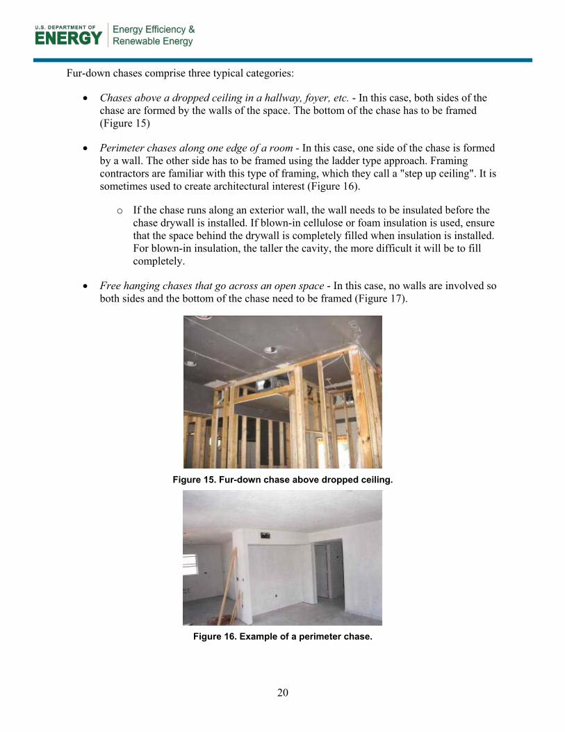
Fur-down chases comprise three typical categories:
• Chases above a dropped ceiling in a hallway, foyer, etc. - In this case, both sides of the chase are formed by the walls of the space. The bottom of the chase has to be framed (Figure 15)
• Perimeter chases along one edge of a room - In this case, one side of the chase is formed by a wall. The other side has to be framed using the ladder type approach. Framing contractors are familiar with this type of framing, which they call a "step up ceiling". It is sometimes used to create architectural interest (Figure 16).
o If the chase runs along an exterior wall, the wall needs to be insulated before the chase drywall is installed. If blown-in cellulose or foam insulation is used, ensure that the space behind the drywall is completely filled when insulation is installed. For blown-in insulation, the taller the cavity, the more difficult it will be to fill completely.
• Free hanging chases that go across an open space - In this case, no walls are involved so both sides and the bottom of the chase need to be framed (Figure 17).
Figure 15. Fur-down chase above dropped ceiling.
Figure 16. Example of a perimeter chase.

21
Figure 17. Free-hanging chase across an open space. Note separation of space accented by
chase.
3.3 System Interaction 3.3.1 Effect of HVAC System Runtime Variable speed compressors combined with multi-speed air handler fans are becoming common in modern, higher efficiency HVAC equipment. To increase efficiency, modern high efficiency HVAC systems can vary their capacity and air flow over a wide range instead of cycling on at full capacity and then cycling off when the thermostat is satisfied. Units designed for hot-humid climates often feature a dehumidification mode that increases latent removal by reducing air handler fan speed to extremely low levels.
These higher efficiency, multi-capacity HVAC units operate for nearly twice as many hours per day as single-capacity systems. Conductive and air leakage losses of the duct system can have a greater impact on these types of systems because conditioned air remains in the ductwork for longer periods of time.
A comparison of interior and attic duct systems was completed in an FSEC experimental facility, a 3-bed 2-bath, 1600 ft2 double-wide manufactured home with a sealed crawl space and a vented attic (Cummings and Withers, 2010). Two heat pump air handler units, a SEER 21 and a SEER 13, were installed side-by-side within the conditioned utility room of the house. The lab has two duct systems—one in the attic and one in an interior fur-down chase. Both systems are reasonably tight. The heat pumps can be attached to either duct system. Using the best-fit equations and a typical summer day with an average outdoor temperature of 82oF, the following energy savings have been found:
• For the SEER 21 system, switching from the attic duct system to the indoor duct system saves 17.3% when employing RH control (45% set-point). Conversely, it can also be stated that switching from the indoor duct system to the attic duct system increases cooling energy use by 20.9%.
• For the SEER 21 system (no RH control active), switching from the attic duct system to the indoor duct system saves 16.8%. Conversely, it can also be stated that switching from the indoor duct system to the attic duct system increases cooling energy use by 20.2%.

22
• For the SEER 13 system, switching from the attic duct system to the indoor duct system saves 11.2%. Conversely, it can also be stated that switching from the indoor duct system to the attic duct system increases cooling energy use by 12.6%.
It is reasonable that the energy penalty associated with using the attic duct system would be much greater for the SEER 21 system compared to the SEER 13 system because the SEER 21 system run time is nearly twice as great as that of the SEER 13 unit (72% of the time for the SEER 21 system versus 38% for the SEER 13 system during hot and humid weather). Therefore, conductive heat transfer from the attic to the duct interior operates for nearly twice the length of time for the SEER 21 unit.
3.3.2 Return Pathways As with all duct systems, adequate return air pathways must be provided. In sealed attics and crawl spaces, duct work can be configured with ducted returns or passive returns using jump ducts (Figure 13) or transoms (Figure 14). It is important to carefully consider how returns will be handled in an interior duct system that relies on chases. If jump ducts or ducted returns are used, more chase will be needed, and overall system cost and complexity will increase. Transoms, or over-the-door returns, and through-the-wall returns, do not add any chase requirements. For a thorough sizing discussion please refer to Building Science Corporation’s Information Sheet at: http://www.buildingscience.com/documents/information-sheets/information-sheet-transfer-grilles-and-ducts. This Information sheet is linked to several other documents that go into great detail about duct sizing, return methods, and their ramifications.
3.3.3 Trade Interactions Due to the nature of constructing an effective chase, it is built early in the construction process, which exposes it to subsequent damage from other trades people involved in the construction process. In sealed attic/crawlspace systems, the location of the air and thermal barrier is often removed from the areas where other trades are typically working, and its function is usually obvious. Such systems are not likely to be mistaken for an architectural detail and used by other trades to run their wires or pipes. Diligent inspection and constant oversight by an informed site supervisor are necessary to ensure that all trades people involved with the process (not just the crew bosses) are aware of the chase and its function. Even after the house is completed, the chase area is subject to damage when the new homeowners have alarm, cable and telephone service installed. Therefore, homeowner awareness of the chase’s function is another important part of successfully implementing an interior duct system.
4 Summary of Implementation of Various Methods
4.1 Integrating the New Strategy Into Current Construction Processes If a sealed attic or crawlspace is chosen, these areas become obvious and easy places to implement an interior duct system. On the other hand, if a conventional insulation system is chosen and a chase is going to be constructed, attention and planning are required from the moment the decision to build a chase is made.

23
4.1.1 Locate Chase Indicate the chase and air handler location on both the mechanical drawings and dimensional drawings (Figure 18). After drafting the chase layout on the plans, detail it in sections for clarity, indicating materials, critical dimensions, and sealing details.
Figure 18. Floor plan, showing the area to have a fur-down chase installed, highlighted in grey.
Clearly communicate both the intent and specifications to all crews working with the chase by providing each group with the plans and detail. This activity may comprise framing, drywall, insulation, and finishing crews as well as the mechanical contractor. Include the electrical and plumbing contractors who need to either avoid putting holes in the chase or fill any hole they create.
Be sure that the mechanical contractor takes the location of the ducts into consideration for system sizing calculations and for the size of the chase (less than 12" clearance for 8' ceilings, Figure 10) for duct sizing calculations. The duct design should incorporate sizing and design considerations to allow adequate air distribution into all rooms. Fur-down chase systems are difficult to use with a perimeter duct installation, as the chase typically runs down the center of the building. Fur-down chases also limit register size and placement.
4.1.2 Before Construction of the Chase Clearly indicate the chase location at the construction site. Much of the chase is built after rough framing and before the mechanical rough-in. A copy of the mechanical system plan showing the

24
duct chase location in hatch marks should be posted in the house for reference. Mark the location of the chase after rough framing. As an example, the construction supervisor responsible for the chase could spray paint the floor along the bottom plate of all the walls where the chase is to be built. The supervisor starts at the air handler and traces the path of the chase to its end (Figure 19). After the chase is installed, mark the location of supply registers (Figure 20).
Figure 19. Paint tags alerting crews to the location of the proposed chase.
Figure 20. Supply duct location marked in the side of a fur-down chase.
Make sure that materials for building the continuous air barrier (and later thermal barrier) are available when needed. If any special materials are required, confirm that they are on hand (light gauge metal framing for the chase support, etc.). To facilitate the construction of a sealed and insulated air handler closet, enabling an air handler that would otherwise be located in an attached garage to be located in “interior” space, some of Building America’s partners have the HVAC contractors construct the air handler closet ceiling with duct board (Fonorow, et al. 2006). This method improves the sealing achieved at this potential leakage point by having the trades people involved with the installation perform the sealing (Figure 21). Not only are these individuals familiar with the material they are using, but they also possess the necessary tools and sealants for completing the task.

25
Figure 21. Air handler closet ceiling constructed with duct board.
4.1.3 General Chase
Construction Guidelines Let the guiding principal for building an interior duct system be the establishment and maintenance of an air barrier. After an air barrier is established, a thermal barrier in the same location is needed. The chase’s ceiling air barrier should be placed first in a fur-down installation. Then all joints and seams should be sealed with code-approved sealant, including the gap between the air barrier and the top plates of adjacent walls. At this point, the chase’s principle air barrier is complete. The rest of the chase will be finished later when the rest of the house is drywalled.
Next, the mechanical system is roughed in, and the rest of the chase is framed. Much of the duct system can be assembled on the floor and then lifted and strapped into place (Figure 22). The remaining chase framing is placed within the chase’s air barrier such that it will not interrupt the house air barrier (Figure 23).
The joints and seams of the chase must be sealed (Figure 24), including any penetrations in the chase that intersect an unconditioned space. Note that unconditioned spaces are any cavity or room that is not served by the mechanical system. These include obvious spaces such as attics, garages and storage rooms as well as hidden areas (e.g. wall and floor cavities).
The penetration in the chase wall for the supply run-out can intersect an unconditioned space or interior wall cavity. To prevent air from travelling down from the attic between the drywall and the top plate, either the joint between the chase wall and the interior wall framing must be sealed, or the joint between the top plate and the drywall must be sealed (Figure 25). Without this
Reference to Other Guidelines, Codes and Standards
The 2009 International Energy Conservation Code (IECC) recognizes sealed crawlspaces (402.2.9) and attics (402.2.2), but not all municipalities have adopted this (or any) energy code.
Exposed foam should meet NFPA 2009 12.5.5.3 requirements for fire-resistance, combustibility, and smoke release standards (NFPA 286, ANSI/UL 1715 and 1040, and FM4880 are test standards to look for).
The local authority should be consulted to ensure that no code issues arise with a sealed attic or crawlspace. A sealed crawlspace is not a viable option in areas where heavy flooding is a concern.
With information derived from the HVAC designers’ ACCA Manual J and D calculations, the home designer can finalize plans which consider the size requirements and path of the distribution system.

26
continuous air barrier, any duct leakage will be in communication with an unconditioned space, either the attic directly or the interior wall cavity. This type of sealing is especially important in the air handler closet since the return side of the air handler induces strong negative pressures, significantly increasing the leakage through any gaps. The simplified fur-down method outline described in section 4.4 of this guideline provides a solution to this issue.
Figure 22. Duct work strapped in place prior to finishing the framing of the chase.
Figure 23. Finish framing for chase.
Figure 24. Air-sealing a fur-up chase.

27
Figure 25. Chase side wall supply sealing detail.
A supervisor who understands the intent of the chase should regularly check progress and follow the chase construction to completion, meaning the ducts are all installed, holes have been sealed, and the chase is ready for close-in. The chase is closed in as the house gets dry-walled.
4.1.4 Protecting the Chase After Completion Protect the chase from cable, phone and other installers who may want to use it as a convenient way to run wires. The holes that typically result will compromise the air barrier. Identifying the chase as a space intended to be separate from surrounding unconditioned spaces is difficult at best. Communication is again an important factor.
Advisory notices to cable, security, and phone installers should be posted in conspicuous locations such as the panel box, attic access hatch, wiring service entrance, etc. Since these notices cannot clearly identify the location of the air boundary in the attic, they should advise the installer to seal any penetrations to drywall made from unconditioned spaces. Though it should be standard practice and is often required by code, virtually all services that are installed post-occupancy are never inspected.

28
4.2 Chase Design 4.2.1 Identify Chase Path Identify the path of the chase or (insulation in case of a sealed attic or crawlspace) on floor plans (Figure 18). The best opportunity to minimize costs while ensuring an aesthetically pleasing outcome is during the preliminary schematic design phase. With information derived from the HVAC designers Manual J and D calculations, the designer can finalize plans which consider the size requirements and path of the distribution system. Thus, less duct material will be used due to preplanning that often involves elimination of many supply runs through the use of side wall supplies connected directly to the main trunk-line. When using side wall supply registers, care must be used to insure that the register is designed to be used on a wall, as opposed to ceiling registers, whose throw patterns will be inappropriate for wall use.
Ducts brought into the conditioned space should include both the return and supply systems to provide maximum efficiency for the effort. In order to reduce the size and amount of chase required, as well as avoiding duct sizing mismatches between the supplies and returns, a passive return system using transoms over the doors (Figure 14) is recommended. The transoms must be sized to ensure that occupiable rooms that can be isolated from the main return by doors are maintained at a nearly negligible difference in pressure with respect to the home (< 2.5 Pascals) when the mechanical system is operating. Returns should be sized at least 1 ½ times larger than the corresponding supply duct areas. The supply ducts should be sized by ACCA Manual D. Detailed sizing information is available from Building Science Corporation’s Information Sheet at: http://www.buildingscience.com/documents/information-sheets/information-sheet-transfer-grilles-and-ducts. This Information sheet is linked to several other documents that go into great detail about duct sizing and its ramifications.
Critical Take-Aways
Indicate the chase and air handler location on both the mechanical drawings and dimensional drawings
Before construction of the chase, clearly indicate the chase location at the construction site.
Let the guiding principal for building an interior duct system be the establishment and maintenance of an air barrier. After an air barrier is established, a thermal barrier in the same location is needed.
After completion, protect the chase from cable, phone and other installers who may want to use it as a convenient way to run wires.
Identify the path of the chase or (insulation in case of a sealed attic or crawlspace) on floor plans
Involve all subcontractors whose work may impact the chase integrity
Multiple to daily inspections needed - Critical times for site supervision are during the drywall installation that will form the air barrier and support the thermal barrier between the chase and attic.
Two critical trades are the home and HVAC design professionals. The best opportunity to minimize costs while ensuring an aesthetically pleasing outcome is during the preliminary schematic design phase of the home. Failure here will result in a poorly implemented end result.
An interior duct system should be planned during a home’s design stage, prior to interior framing, since it would be difficult, although possible, to implement after this stage. An interior duct system is not often suitable for retrofit unless a sealed attic or crawlspace is created.
Adequate return air pathways from closable rooms to the air handler must be provided, regardless of duct system style.
All return duct work can be eliminated by using over-the-door transom or through-the-wall returns from bedrooms.

29
Another benefit is that by eliminating all ducted returns, labor and material costs are reduced. In addition, the system’s overall operating static pressure is reduced, reducing the fan motor power requirements and allowing for less wear on the air handler fan motor.
From a residential designer’s perspective, incorporating the chases within the space should be negligible in terms of complicating the design process. In fact, as previously mentioned, adding dropped soffits in strategic areas can help define the character of the interior spaces.
4.2.2 Involve All Subcontractors Whose Work May Impact the Chase Integrity The next step is to have a team meeting on-site after the home has been “dried in”. The objective is to minimize the need to alter or redo work due to a lack of knowledge of the requirements. One of the partner builders prefers to lead a meeting that provides him with the opportunity to clearly communicate that the home will be built differently compared to the normal practice of having ducts in the attic. The builder also expresses his expectations regarding quality of workmanship and the importance of a collaborative effort in accomplishing his goals. Key trades represented in the meeting included the designer, sales/marketing professionals, and mechanical, insulation, plumbing, electrical, framing, sheet rockers and solar contractors. Questions raised in the discussion are quickly answered by the appropriate representative. Generally after the construction of the first prototype home, additional team meetings for subsequent homes are generally unnecessary as long as the site work force remains the same.
4.3 Field Inspection 4.3.1 Multiple to Daily Inspections Needed The integrity of the air barrier between the interior and the attic is paramount. The first and most critical inspection of the process is the initial installation of ceiling drywall. The site supervisor must be aware that even if the subcontractors and employees are informed about the chase and its function, the actual workers on the job site may be unaware of this component. Indeed, it only takes a moment to defeat the integrity of any fur-up or down installation. Critical times for site supervision are during the drywall installation that will form the air barrier and support the thermal barrier between the chase and attic.
4.4 Introduction of Detailed, Simplified, and Inexpensive Method of a Fur-down Chase
The main obstacle to successfully implementing interior duct work via fur-down chases has been the inability to thoroughly seal the chase from the above unconditioned attic. The chase is difficult to seal at the multitude of wall/ceiling intersections (Figure 25).
By keeping the top plate of the non-load bearing interior walls ¾” + from the bottom chord of the roof trusses, ceiling drywall can be slipped though this space. Intersections of the ceiling and wall framing members are eliminated and the ceiling drywall (and upper air barrier of the chase) can be continuous. By eliminating the leakage paths to the unconditioned space, any remaining chase leakage is contained to the inside of the house.
All return duct work is eliminated by using a central return plenum under the air handler and over the door transom returns from bedrooms. This configuration has the added benefit of

30
reduced labor and material costs. Sections 4.4.1 through 4.4.5 provide a more detailed discussion of this approach.
4.4.1 Install Ceiling/Chase Drywall The first step after completing the design work is to have the chase ceiling sheet rock installed as indicated in the design plan. Interior walls are mounted as if an interior duct system will not be included in the configuration. The exception, however, is that a second top plate is not installed where the chase is to be situated. By keeping the top plate of the non-load bearing interior walls ¾” + from the bottom chord of the roof trusses (Figure 26), the drywall can be slipped though this space. A second top plate or pieces of blocking for rigidity of interior walls can be installed later. This provides a very easy method to create an excellent air barrier between the conditioned and unconditioned space, as it virtually eliminates intersections of ceiling and wall framing, which are difficult to seal. In addition, it causes any remaining chase leakage (the sides and bottom) to leak to the inside of the house, eliminating the negative impacts of leakage to the outside. This process also eliminates the need for much of the excess wood ordinarily required to support the chase drywall, and removes much of the excess drywall waste created from cutting small pieces for creating an air barrier in small spaces. It also reduces labor costs; however, it does require an additional visit from the drywall contractor, for the home will not be ready for the rest of the drywall until a later stage of construction.
Figure 26. Ceiling drywall installed at fur-down chase top. Drywall is slid through a ¾”+ gap
between the wall top plate and the truss bottom chord, ensuring a good air barrier.
4.4.2 Install Duct Work The supply ductwork is installed under the drywall after being fabricated and sealed on the ground as much as practical. The main supply trunk lines and supply ducts are then hung from the drywall using 2” nylon strapping material (Figure 27). Rigid ductboard ducts are used whenever possible, and are sometimes required due to chase height limitations, as previously discussed. Studs in the interior walls that obstruct the chase are adjusted or removed. Nailers are fitted to allow for attachment of the drywall. This process can be planned in advance, and walls can be framed to accommodate the chase; however, it may be easier to make adjustments after the framing crew completes their work.

31
Figure 27. Duct work hung with 2” strapping after chase ceiling drywall installed and sealed.
4.4.3 Finish Chase Construction After the duct work is sealed and hung, the rest of the chase is constructed and installed to provide nailing surfaces for the remaining drywall (Figure 28).
Figure 28. Chase sides and bottom installed.
4.4.4 A Method to Reduce the Size of the Chase To provide supply ducts off the main truck line, duct installers typically will cut a hole in the trunk line and insert a collar to accept a section of flex duct. The other end of the flex duct will be connected to the supply boot. This method results in a chase that is wider than necessary (Figure 29). By field fabricating a shallow duct board box and affixing it directly to the trunk line, the width of the chase can be reduced by almost a foot (Figure 30 and 31). This improved method provides better air flow, greater design opportunities, and reduced costs.
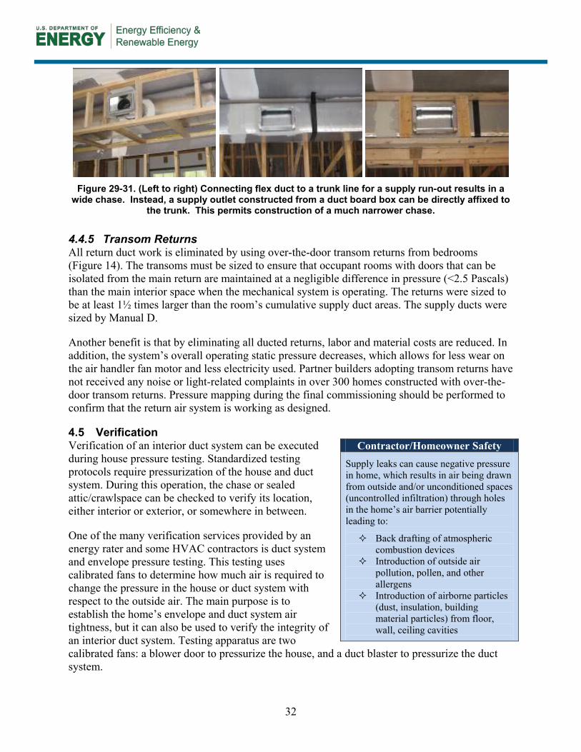
32
Figure 29-31. (Left to right) Connecting flex duct to a trunk line for a supply run-out results in a
wide chase. Instead, a supply outlet constructed from a duct board box can be directly affixed to the trunk. This permits construction of a much narrower chase.
4.4.5 Transom Returns All return duct work is eliminated by using over-the-door transom returns from bedrooms (Figure 14). The transoms must be sized to ensure that occupant rooms with doors that can be isolated from the main return are maintained at a negligible difference in pressure (<2.5 Pascals) than the main interior space when the mechanical system is operating. The returns were sized to be at least 1½ times larger than the room’s cumulative supply duct areas. The supply ducts were sized by Manual D.
Another benefit is that by eliminating all ducted returns, labor and material costs are reduced. In addition, the system’s overall operating static pressure decreases, which allows for less wear on the air handler fan motor and less electricity used. Partner builders adopting transom returns have not received any noise or light-related complaints in over 300 homes constructed with over-the-door transom returns. Pressure mapping during the final commissioning should be performed to confirm that the return air system is working as designed.
4.5 Verification Verification of an interior duct system can be executed during house pressure testing. Standardized testing protocols require pressurization of the house and duct system. During this operation, the chase or sealed attic/crawlspace can be checked to verify its location, either interior or exterior, or somewhere in between.
One of the many verification services provided by an energy rater and some HVAC contractors is duct system and envelope pressure testing. This testing uses calibrated fans to determine how much air is required to change the pressure in the house or duct system with respect to the outside air. The main purpose is to establish the home’s envelope and duct system air tightness, but it can also be used to verify the integrity of an interior duct system. Testing apparatus are two calibrated fans: a blower door to pressurize the house, and a duct blaster to pressurize the duct system.
Contractor/Homeowner Safety
Supply leaks can cause negative pressure in home, which results in air being drawn from outside and/or unconditioned spaces (uncontrolled infiltration) through holes in the home’s air barrier potentially leading to:
Back drafting of atmospheric combustion devices
Introduction of outside air pollution, pollen, and other allergens
Introduction of airborne particles (dust, insulation, building material particles) from floor, wall, ceiling cavities

33
4.5.1 Blower Door Testing Typical blower door testing involves depressurizing the house to a standard pressure with respect to the outside, usually 50 Pascals. When the house is subjected to this depressurization, the pressure in the area with the duct work (foamed attic/crawlspace or chase) can be checked with respect to the house. If there is no pressure difference between the house and chase, the duct area is truly interior. In other words, it is completely inside the pressure boundary of the house. Depending on the pressure size, a determination can be made regarding the integrity of the interior duct system.
4.5.2 Duct Blaster Testing Two tests can be performed with the duct blaster, one that measures the leakage of the entire duct system - both into the interior and exterior of the house, and a second test that measures the duct leakage to the exterior of the building only. The results of the second test, leakage to the outside, are important regardless of duct style; leakage to the outside is energy lost as well as the cause of pressure differences described earlier that can lead to other building science problems related to moisture management, comfort, and indoor air quality.
The original idea for designing interior duct systems was to eliminate duct leakage to the outside. If the crawlspace/attic or chase is completely sealed from the outside, there can be no duct leakage to the outside. Obviously, leakage results here indicate that the duct system is connected to the outside in some fashion, indicating a breakdown in the air barrier in the chase or sealed attic/crawlspace.
4.5.3 Room to Main Body Pressure Balancing
Adequate return air pathways from closable rooms to the air handler must be provided, regardless of duct system style. While operating the HVAC system’s air handler, fan pressure mapping of the various closable rooms in the house with respect to the main body of the house should be performed. If any pressures between rooms and the main body of the house exceed 2.5 Pascals, remedial action should be taken to reduce the pressure to less than 2.5 Pascals.
Critical Take-Aways
The 2009 International Energy Conservation Code (IECC) recognizes sealed crawlspaces (402.2.9) and attics (402.2.2), but not all municipalities have adopted this (or any) energy code.
Exposed foam should meet NFPA 2009 12.5.5.3 requirements for fire-resistance, combustibility, and smoke release standards (NFPA 286, ANSI/UL 1715 and 1040, and FM4880 are test standards to look for).
The local authority should be consulted to ensure that no code issues arise with a sealed attic or crawlspace. A sealed crawlspace is not a viable option in areas where heavy flooding is a concern.
With information derived from the HVAC designers’ ACCA Manual J and D calculations, the home designer can finalize plans which consider the size requirements and path of the distribution system.

34
References
Building Science Corporation. “Transfer Ducts and Grilles for All Climates,” BSC Information Sheet 604. November 2008. http://www.buildingscience.com/documents/information-sheets/information-sheet-transfer-grilles-and-ducts/files/bscinfo_604_transfer_grilles.pdf Cummings, J., C. Withers. “Energy Savings and Peak Demand Reduction of a SEER 21 Heat Pump vs. a SEER 13 Heat Pump with Attic and Indoor Duct Systems - Phase 1 Report,” Florida Solar Energy Center, Rpt: FSEC-CR-1877-10, Dec. 22, 2010 Hales, D., and D. Baylon. “Moving Ducts into Conditioned Space: Getting to Code in the Pacific Northwest.” ASHRAE Transactions, 116, Part 1. McIlvaine, J., D. Beal, S. Chandra, "Gulf Coast High Performance Affordable Housing Demonstration Project." Florida Solar Energy Center, Rpt: FSEC-CR-1791-09, Feb. 05, 2009 http://fsec.ucf.edu/en/publications/pdf/FSEC-CR-1791-09.pdf Fonorow, K., Chandra, S., Martin, E., McIlvaine, J., "Energy and Resource Efficient Communities through Systems Engineering: Building America Case Studies in Gainesville, FL." Proceedings of the 2006 Summer Study on Energy Efficiency in Buildings, American Council for an Energy Efficient Economy, Asilomar, CA., August 2006. http://www.baihp.org/pubs/aceee_fonorow/index.pdf Beal, D., D. Chasar, "Measured Crawlspace Conditions in a HUD-code Home." Florida Solar Energy Center, Rpt: FSEC-PF-418-06, Jul. 24, 2006 http://securedb.fsec.ucf.edu/pub/pub_show_detail?v_pub_id=4263 Lubliner, M., Kerr, R., Gordon, A., and C. Murray. “Moving Ducts Inside: Big Builders, Scientists Find Common Ground.” Proceedings ACEEE 2008. http://www.energy.wsu.edu/documents/AHT_ACEEE%20Ducts%20inside%5B1%5D.pdf Moyer, N., Stroer, D., Hoak, D., McIlvaine, J., and Chandra, S., "Research Results from A Few Alternate Methods of Interior Duct Systems in Factory Built Housing Located In the Hot Humid Climate", Sixteenth Symposium on Improving Building Systems in Hot and Humid Climates, December 15-17, 2008, Dallas, TX. http://www.fsec.ucf.edu/en/publications/pdf/FSEC-PF-444-08.pdf

35
Acknowledgments
The previous work was sponsored by the U.S. Department of Energy (DOE), Office of Energy Efficiency and Renewable Energy, and the Building America Program under cooperative agreement number DE-FC26-06NT42767.and DOE, National Energy Technology Laboratory (NETL), Cooperative Agreement DE-FC26-99FT40642. The support and encouragement of Mr. George James, Mr. Terry Logee, Mr. Ed Pollock, Mr. Esher Kweller and Mr. William Haslebacher is gratefully acknowledged. This support does not constitute DOE endorsement of the views expressed in this paper.
The authors acknowledge the leadership and support of Dr. Subrato Chandra, the project manager for this research conducted under the Building America Industrialized Housing Project. In addition, the authors appreciate the cooperation and support of our builder and developer partners, especially Tommy Williams Homes, Bentwood Custom Homes in Dallas TX, Durham County Habitat for Humanity, NC, and Broward County Habitat for Humanity, FL, in performing this work. We appreciate the editorial assistance from Ms. Danielle Daniel of FSEC and Ms Andy Fonorow of Florida H.E.R.O.

DOE/GO-102011-3421 ▪ November 2011
Printed with a renewable-source ink on paper containing at least 50% wastepaper, including 10% post-consumer waste.