Mean-Value Internal Combustion Engine Model: Real-Time ...
12
Mean-Value Internal Combustion Engine Model: Real-Time Execution in NI Veristand TM Introduction The development of high-fidelity predictive models of vehicle engines is a major preoccupation of powertrain engineers. By developing “virtual” prototypes of their engine designs, automotive manufacturers can obtain tremendous insight into the behavior of the engine, particularly for controller design and development, to maximize performance while complying with governmental and ecological con- straints. Doing this before investing in the prototyping stages has been proven to save significant time and costs during the product development process. In a previous article, “Mean-Value Internal Combustion Engine Model with MapleSim™”, we described the development of a high-fidelity model of an internal combustion engine based on the underlying equations describing the behavior of the different components. The “mean-value” approach essentially ignores the cyclic details of the engine, such as crank rotation, piston motion, gas compression/expansion and ignition, and provides the overall power/torque/ speed output in response to the mass of air/fuel mixture flowing into the engine. This approach is particularly favored by powertrain control developers because the models deal only with the properties of the system the engineers are interested in (in this case, engine torque and speed), and the models are faster to simulate. Now that we have the model, the next step is test the model in a real-time simulation environment. MapleSim supports real-time modeling toolchains from both The MathWorks™ and National Instruments™. This article will demonstrate the process of preparing and deploying the MapleSim engine model to a National Instruments real-time platform using the new real-time testing software, NI VeriStand™. NI VeriStand is a ready- to-use software environment for con- figuring real-time testing applications, including hardware-in-the-loop (HIL) test systems. This process illustrates how MapleSim provides a very intuitive environment for developing models. These models are then used in real-time simulations, resulting in a development cycle that takes a fraction of the time and cost of any other modeling approach. High-Performance Physical Modeling and Simulation
Transcript of Mean-Value Internal Combustion Engine Model: Real-Time ...

Mean-Value Internal Combustion Engine Model: Real-Time Execution in NI VeristandTM
IntroductionThe development of high-fidelity predictive models of vehicle engines is a major preoccupation of powertrain engineers. By developing “virtual” prototypes of their engine designs, automotive manufacturers can obtain tremendous insight into the behavior of the engine, particularly for controller design and development, to maximize performance while complying with governmental and ecological con-straints. Doing this before investing in the prototyping stages has been proven to save significant time and costs during the product development process.
In a previous article, “Mean-Value Internal Combustion Engine Model with MapleSim™”, we described the development of a high-fidelity model of an internal combustion engine based on the underlying equations describing the
behavior of the different components. The “mean-value” approach essentially ignores the cyclic details of the engine, such as crank rotation, piston motion, gas compression/expansion and ignition, and provides the overall power/torque/speed output in response to the mass of air/fuel mixture flowing into the engine. This approach is particularly favored by powertrain control developers because the models deal only with the properties of the system the engineers are interested in (in this case, engine torque and speed), and the models are faster to simulate.
Now that we have the model, the next step is test the model in a real-time simulation environment. MapleSim supports real-time modeling toolchains from both The MathWorks™ and National Instruments™.
This article will demonstrate the process of preparing and deploying the MapleSim engine model to a National Instruments real-time platform using the new real-time testing software, NI VeriStand™. NI VeriStand is a ready-to-use software environment for con-figuring real-time testing applications, including hardware-in-the-loop (HIL) test systems. This process illustrates how MapleSim provides a very intuitive environment for developing models. These models are then used in real-time simulations, resulting in a development cycle that takes a fraction of the time and cost of any other modeling approach.
High-Performance Physical Modeling and Simulation

Model Preparation The mean-value engine model, shown in Figure 1, was developed using published equations from several industry-stan-dard texts (see the References section), implemented as custom components in MapleSim. It demonstrates the use of signal-flow (or causal) and topological (or acausal) modeling techniques in combination.
The engine model is composed of three main subsystems: the throttle, the intake manifold, and engine power genera-tion from the fuel combustion. Load-ing on the engine shaft is provided by
a model of a dynamometer, acausally connected to the engine drive shaft. The engine speed is determined by a simple controller that regulates the angle of the throttle valve, which in turn controls the air/fuel mass flow through the throttle, the manifold and into the engine.
To prepare the model for code gen-eration and real-time implementation, three steps must be performed:
1) Identify which parts of the model will be exported and gather them into a single subsystem in MapleSim;
2) Define which properties will be in-puts to and outputs from the subsystem; and
3) Define the subsystem parameters, identifying those that will be hard-coded and those that the user will be able to edit in NI VeriStand.
Mean-Value IC Engine Model
Figure 1: Mean-value engine model in MapleSim
Figure 2: Definition of exported subsystem, “CompleteEngine”
1. Create a Subsystem of the Model Components to be ExportedTo define which parts of the model to export, you need to select the required components and gather them into a subsystem component. In this case, the throttle, manifold, engine, and dynamometer (load) subsystems were selected and combined into a subsystem called “CompleteEngine.”
Mean-Value Internal Combustion Engine Model: Real-Time Execution in NI VeriStand™
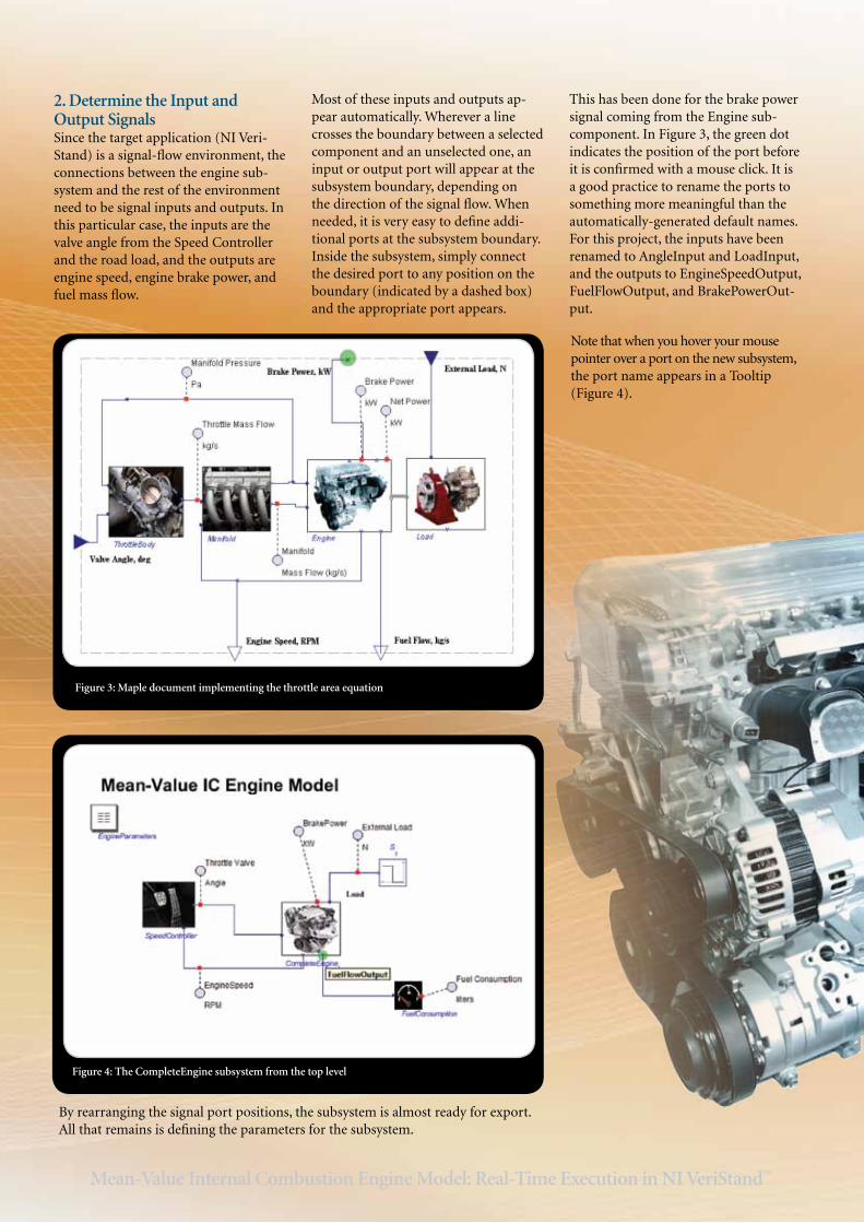
Figure 3: Maple document implementing the throttle area equation
2. Determine the Input and Output SignalsSince the target application (NI Veri-Stand) is a signal-flow environment, the connections between the engine sub-system and the rest of the environment need to be signal inputs and outputs. In this particular case, the inputs are the valve angle from the Speed Controller and the road load, and the outputs are engine speed, engine brake power, and fuel mass flow.
Most of these inputs and outputs ap-pear automatically. Wherever a line crosses the boundary between a selected component and an unselected one, an input or output port will appear at the subsystem boundary, depending on the direction of the signal flow. When needed, it is very easy to define addi-tional ports at the subsystem boundary. Inside the subsystem, simply connect the desired port to any position on the boundary (indicated by a dashed box) and the appropriate port appears.
This has been done for the brake power signal coming from the Engine sub-component. In Figure 3, the green dot indicates the position of the port before it is confirmed with a mouse click. It is a good practice to rename the ports to something more meaningful than the automatically-generated default names. For this project, the inputs have been renamed to AngleInput and LoadInput, and the outputs to EngineSpeedOutput, FuelFlowOutput, and BrakePowerOut-put.
Note that when you hover your mouse pointer over a port on the new subsystem, the port name appears in a Tooltip (Figure 4).
Figure 4: The CompleteEngine subsystem from the top level
By rearranging the signal port positions, the subsystem is almost ready for export. All that remains is defining the parameters for the subsystem.
Mean-Value Internal Combustion Engine Model: Real-Time Execution in NI VeriStand™

3. Define the System ParametersBefore the export process, all the pa-rameters used by the CompleteEngine subsystem must be defined within the subsystem, so they are properly exported and available from NI VeriStand. These parameters will be divided into two groups: those whose values can be modified from within NI VeriStand, and those whose values should be defined as constants in the generated code.
In MapleSim, parameter definitions are scoped. Parameter values defined at one level of the model hierarchy are inher-ited by all its subsystems, unless they are explicitly overridden at a lower level. This means you can define the param-eter values at the top level and these will be used throughout the model hierarchy. You can then override a parameter value for use in a particular subsystem, or even
set new and different values for the same parameter in different subsystems. Man-aging these parameters and their differ-ent values is done through parameter blocks. In this case, in order to ensure all values needed by the Complete Engine model are properly exported, all param-eters need to be explicitly defined at the level of the CompleteEngine subsystem. This is easily achieved by copying the Engine Parameters block at the top level and pasting it into the CompleteEngine subsystem.
The next step is to define which param-eters should be modifiable by the user from within NI VeriStand. For the pur-pose of this project, throttle diameter, stroke, bore, number of cylinders and the fuel internal heat value were made available as user-editable parameters. During the export process, all other parameters are hard-coded as constants.
To make these values user-editable from within NI VeriStand, they must be declared as local parameters to the CompleteEngine subsystem. This is done using the Parameter Editor, which is opened by clicking the Parameter Editor button. Because these param-eters will be receiving their values from elsewhere, the default value is set to the parameter’s own name (see Figure 5 and Figure 6). Before the export process, the effect is that the local parameter, Dt (for example), will take on the value of the global Dt, which is defined at the top level. After the export process, Dt will be given its value based on the NI VeriStand settings, using the MapleSim global value as the default.
Figure 5: Opening the Parameter Editor and entering the local parameters
Finally, a little cleanup. The parameters which have just been declared to be local are now declared twice at the level of the CompleteEngine subsystem – once in the parameter block, and once in the local parameter list. While parameters can be defined with different values at different places in the model hierarchy, they cannot appear more than once at the same level. Therefore, these names must be removed from the parameter block.
Figure 6: User-defined local parameters for the CompleteEngine subsystem
Mean-Value Internal Combustion Engine Model: Real-Time Execution in NI VeriStand™
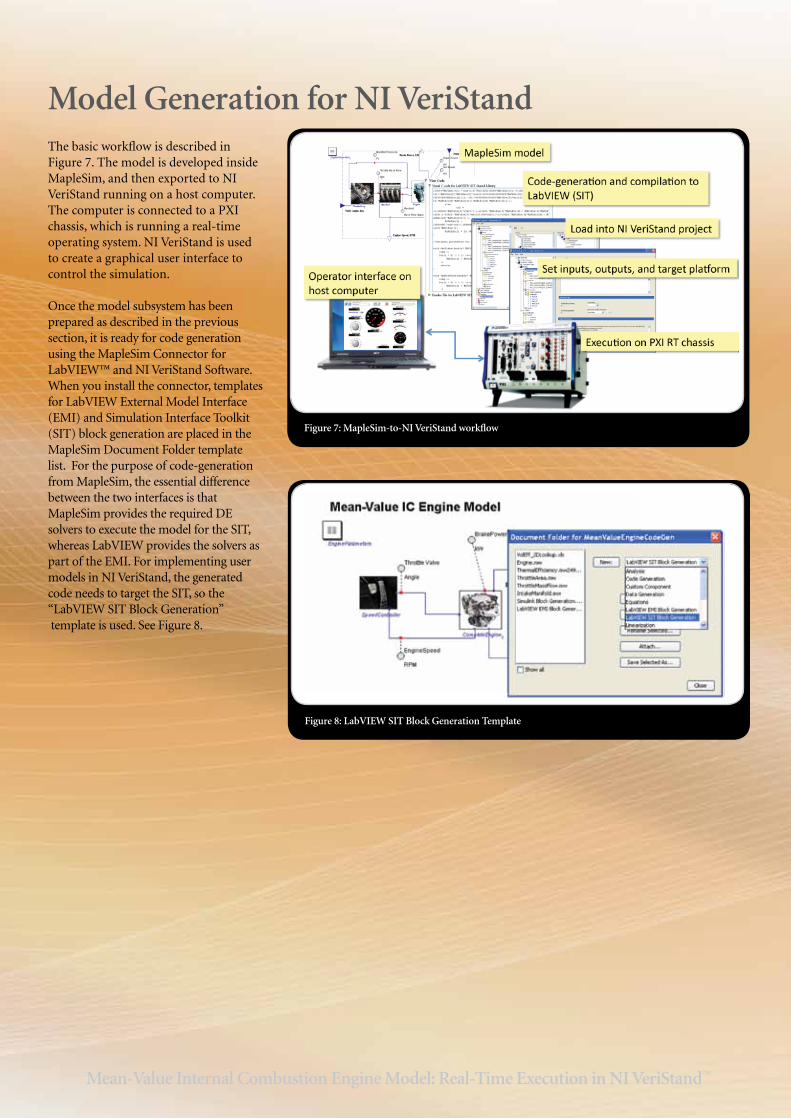
Model Generation for NI VeriStandThe basic workflow is described in Figure 7. The model is developed inside MapleSim, and then exported to NI VeriStand running on a host computer. The computer is connected to a PXI chassis, which is running a real-time operating system. NI VeriStand is used to create a graphical user interface to control the simulation.
Once the model subsystem has been prepared as described in the previous section, it is ready for code generation using the MapleSim Connector for LabVIEW™ and NI VeriStand Software. When you install the connector, templates for LabVIEW External Model Interface (EMI) and Simulation Interface Toolkit (SIT) block generation are placed in the MapleSim Document Folder template list. For the purpose of code-generation from MapleSim, the essential difference between the two interfaces is that MapleSim provides the required DE solvers to execute the model for the SIT, whereas LabVIEW provides the solvers as part of the EMI. For implementing user models in NI VeriStand, the generated code needs to target the SIT, so the “LabVIEW SIT Block Generation” template is used. See Figure 8.
Figure 7: MapleSim-to-NI VeriStand workflow
Figure 8: LabVIEW SIT Block Generation Template
Mean-Value Internal Combustion Engine Model: Real-Time Execution in NI VeriStand™
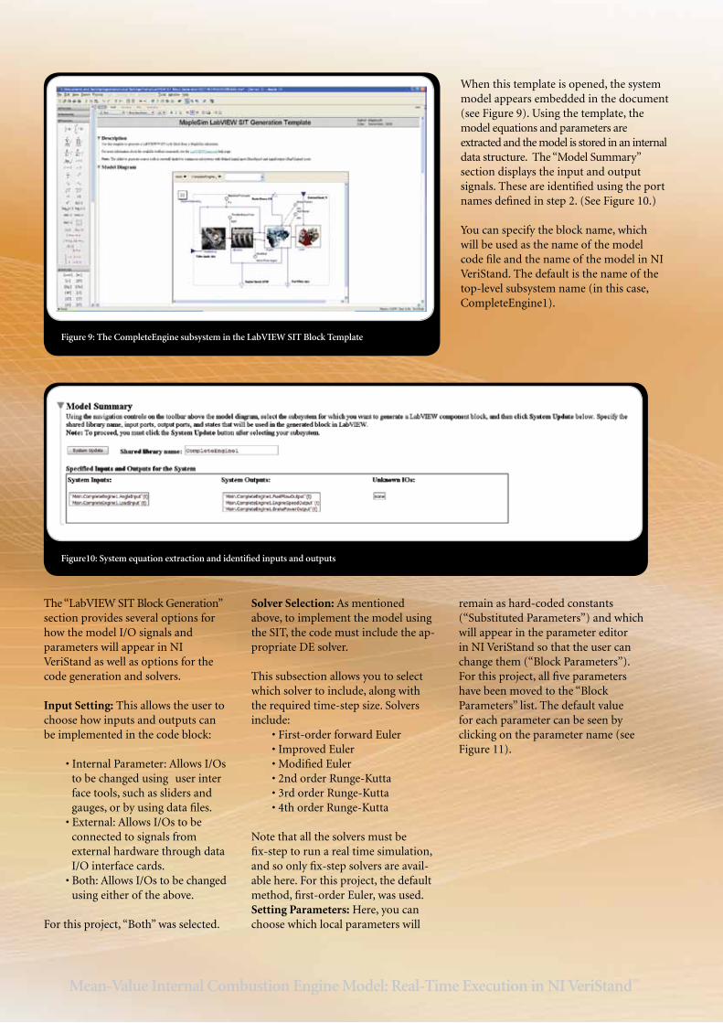
When this template is opened, the system model appears embedded in the document (see Figure 9). Using the template, the model equations and parameters are extracted and the model is stored in an internal data structure. The “Model Summary” section displays the input and output signals. These are identified using the port names defined in step 2. (See Figure 10.)
You can specify the block name, which will be used as the name of the model code file and the name of the model in NI VeriStand. The default is the name of the top-level subsystem name (in this case, CompleteEngine1).
Figure 9: The CompleteEngine subsystem in the LabVIEW SIT Block Template
Figure10: System equation extraction and identified inputs and outputs
The “LabVIEW SIT Block Generation” section provides several options for how the model I/O signals and parameters will appear in NI VeriStand as well as options for the code generation and solvers.
Input Setting: This allows the user to choose how inputs and outputs can be implemented in the code block:
•InternalParameter:AllowsI/Os to be changed using user inter face tools, such as sliders and gauges, or by using data files. •External:AllowsI/Ostobe connected to signals from external hardware through data I/O interface cards. •Both:AllowsI/Ostobechanged using either of the above.
For this project, “Both” was selected.
Solver Selection: As mentioned above, to implement the model using the SIT, the code must include the ap-propriate DE solver.
This subsection allows you to select which solver to include, along with the required time-step size. Solvers include: •First-orderforwardEuler •ImprovedEuler •ModifiedEuler •2ndorderRunge-Kutta •3rdorderRunge-Kutta •4thorderRunge-Kutta
Note that all the solvers must be fix-step to run a real time simulation, and so only fix-step solvers are avail-able here. For this project, the default method, first-order Euler, was used.Setting Parameters: Here, you can choose which local parameters will
remain as hard-coded constants (“Substituted Parameters”) and which will appear in the parameter editor in NI VeriStand so that the user can change them (“Block Parameters”). For this project, all five parameters have been moved to the “Block Parameters” list. The default value for each parameter can be seen by clicking on the parameter name (see Figure 11).
Mean-Value Internal Combustion Engine Model: Real-Time Execution in NI VeriStand™
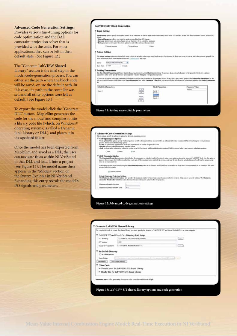
Advanced Code Generation Settings: Provides various fine-tuning options for code optimization and the DAE constraint projection solver that is provided with the code. For most applications, they can be left in their default state. (See Figure 12.) The “Generate LabVIEW Shared Library” section is the final step in the model code-generation process. You can either set the path where the block code will be saved, or use the default path. In this case, the path to the compiler was set, and all other options were left as default. (See Figure 13.) To export the model, click the “Generate DLL” button. MapleSim generates the code for the model and compiles it into a library code file (which, on Windows® operating systems, is called a Dynamic Link Library or DLL), and places it in the specified folder.
Once the model has been exported from MapleSim and saved as a DLL, the user can navigate from within NI VeriStand to that DLL and load it into a project (see Figure 14). The model name then appears in the “Models” section of the System Explorer in NI VeriStand. Expanding this entry reveals the model’s I/O signals and parameters.
Figure 11: Setting user-editable parameters
Figure 12: Advanced code generation settings
Figure 13: LabVIEW SIT shared library options and code generation
Mean-Value Internal Combustion Engine Model: Real-Time Execution in NI VeriStand™
NI VeriStand provides a configuration panel for assigning the execution of the model or model subsystems on any ap-propriate processor connected to the host system via a standard ethernet network. For this project, the complete model including the controller was assigned to a PXIe-8108 real-time controller, with no external I/O signals.
NI VeriStand also provides tools for managing the system I/Os, test proce-dures and data logging through a series of configuration panels. These were used to create a real-time test, running the engine model on the real-time platform, and interfaced with a UI panel on the host computer. In addition to the user interface, the NI VeriStand “Calculated Channel” panel was used to compute the fuel consumed by integrating the fuel mass flow and dividing by the fuel density (Figure 15). This value is displayed in the user interface for the model.
For the user interface, two knob controls are provided to allow the user to manu-ally set the desired engine speed and the
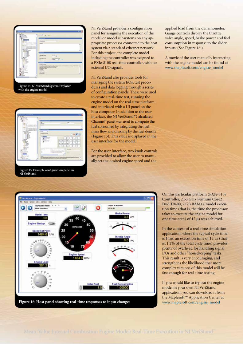
applied load from the dynamometer. Gauge controls display the throttle valve angle, speed, brake power and fuel consumption in response to the slider inputs. (See Figure 16.)
A movie of the user manually interacting with the engine model can be found at www.maplesoft.com/engine_model
On this particular platform (PXIe-8108 Controller, 2.53 GHz Pentium Core2 Duo T9400, 2 GB RAM) a model execu-tion time (that is, the time the processor takes to execute the engine model for one time-step) of 12 μs was achieved.
In the context of a real-time simulation application, where the typical cycle time is 1 ms, an execution time of 12 μs (that is, 1.2% of the total cycle time) provides plenty of overhead for handling signal I/Os and other “housekeeping” tasks. This result is very encouraging, and strengthens the likelihood that more complex versions of this model will be fast enough for real-time testing.
If you would like to try out the engine model in your own NI VeriStand application, you can download it from the Maplesoft™ Application Center at www.maplesoft.com/engine_modelFigure 16: Host panel showing real-time responses to input changes
Figure 14: NI VeriStand System Explorer with the engine model
Figure 15: Example configuration panel in NI VeriStand
Mean-Value Internal Combustion Engine Model: Real-Time Execution in NI VeriStand™

Further WorkThe engine model described in this article was phase one of an ongoing project to produce a realistic, parameterized mean-value model for a range of internal com-bustion engines. Based on feedback from industrial experts, there is a growing list of enhancements that will be made to the model as the project progresses. These include variation of air/fuel ratio (currently assumed constant), effects of ignition and variable valve timing (VVT), as well as the addition of components such as turbo-chargers and catalytic converters.
The next phase of the engine model will include transmission and drivetrain models so that the model can be used with published driving cycles; this will allow the model to be fully validated against other engine models and real engine test data. The real-time implementation will be further developed to include signal I/O and a real Engine Control Unit (ECU), connected to the model via an appropriate communications interface, such as CANbus. This work will be done in NI Veri-Stand as well as other systems.
ConclusionThis project demonstrates the process of preparing a mean-value engine model and then converting it to C code for implementation in a real-time simulation platform using NI VeriStand. The project illustrates the ease and speed with which this process can be carried out: from preparation to real-time implementation, the process took less than half a day by an engineer with moderate knowledge of MapleSim and NI VeriStand. While the current model still requires further details which will add to the model complexity, the performance results are very encour-aging. Even if the enhanced model increased the execution speed ten-fold, the results would still be well within the typical time step limit. Even a significantly more complex engine model developed in MapleSim would be easily transferable into NI VeriStand for real-time simulation.
MapleSim provides a very easy-to-use environment for developing models and generating C code from the model equations that is fully optimized for real-time execution in NI VeriStand. The result is a model development process that takes a fraction of the time and cost of any other modeling approach.
AcknowledgementsThis project is based on the work of Mohammadreza Saeedi, at the University of Waterloo, supervised by Dr. Roydon Fraser and Dr. John McPhee. Maplesoft also owes a debt of gratitude to Joseph Lomonaco at Harley-Davidson for invaluable industrial guidance during the development of this model.
References
Maplesoft: Mean-value Internal Combustion Engine Model with MapleSim, www.maplesoft.com/engine_model
Cook,J.A.,Powell,B.,K.,DiscreteSimplifiedExternal Linearization and Analytical Com-parison of IC Engine Families, Proceedings of the American Control Conference, 1987.
Crossley, P. R., Cook, J. A., A Nonlinear Engine Model for Drive Train System Development. Proceedings of IEEE International Confer-ence., Control’91, 2:921–925, Conference publication332,Edinburgh,UK,(1991).
Dobner, D. J., A Mathematical Engine Model for Development of Dynamic Engine Control, SAE 800054.
Dawson, J. A., An Experimental and Compu-tational Study of Internal Combustion Engine Modeling for Controls Oriented Research, Ph. D. dissertation, Ohio State University, 1998.
Gillespie, T. D., Fundamentals of Vehicle Dynamics, SAE International., 1992
Guzzella, L., Onder, C. H., Introduction to Modeling and Control of Internal Combus-tion Engine Systems, Springer, 2004
Hendricks, E., Chevalier, A., Jensen, M., So-renson, S. C., Modeling of the Intake Manifold Filling Dynamics, SAE 960037
Hendricks, E., Sorenson, S. C., Mean Value Modeling of Spark Ignition Engines, SAE 900616
Hendricks, E, Vesterholm, T., The Analysis of Mean Value SI Engine Models, SAE 920682.
Heywood, J. B., Internal Combustion Engine Fundamentals, McGraw Hill, 1988.
Moskwa, J. J., Automotive Engine Modeling for Real-Time Control Using MATLAB®/Simulink®, SAE 950417.
Moskwa, J. J., Automotive Engine Modeling for Real-Time Control, Ph.D. dissertation, Massachusetts Institute of Technology, 1988.
Yuen, W.W., A Mathematical Engine Model Including the Effect of Engine Emissions, SAE 840036.

Notes:

Notes:

www.maplesoft.com | [email protected] Toll-free: (US & Canada) 1-800-267-6583 | Direct:1-519-747-2373
© Maplesoft, a division of Waterloo Maple Inc., 2011. Maplesoft, Maple, and MapleSim are trademarks of Waterloo Maple Inc. LabVIEW, National Instruments, and NI VeriStand are trademarks of National Instruments. MATLAB, Simulink, and The MathWorks are trademarks or registered trademarks of The MathWorks, Inc.