MDT Materials Manual Section 300 Hot Mix Pavement 300 SECTION HOT MIX PAVEMENT Test Date of Method...
70
1 of 2 Rev. 12/31/17 CURRENT DATE OF REVISION MT 300 SECTION HOT MIX PAVEMENT Test Date of Method Publication No. Title Pages or Revision MT 301 Vacant MT 302 Sampling and Testing Bituminous Materials ................................................. 2 pp Jul 2014 MT 303 Sampling Bituminous Paving Mixtures .......................................................... 3 pp Jul 2014 MT 304 Moisture Test on Plant Mix Bituminous Surfacing Aggregates ..................... 2 pp Jul 2014 MT 305 Volume Swell of Bituminous Mixtures ........................................................... 6 pp May 2009 MT 306 Vacant MT 307 Vacant MT 308 Vacant MT 309 Eliminated (Use AASHTO R 47 Reducing Samples of Hot Mix Asphalt to Testing Size) MT 310 Determining the Macro-Texture of a Pavement Surface ............................... 6 pp Dec 2017 MT 311 Vacant MT 312 Eliminated (Use AASHTO T 329 Moisture Content of Asphalt Mixtures by Oven Method) MT 313 Vacant MT 314 Eliminated (Use AASHTO T 166 Bulk Specific Gravity (Gmb) of Compacted Asphalt Mixtures Using Saturated Surface-Dry Specimens) MT 315 Vacant MT 316 Method of Sampling Recycled Pavement and Field Control of Recycle Paving .............................................................................................. 5 pp Jun 2004 MT 317 Vacant MT 318 Vacant MT 319 Determining the Asphalt Binder Content of Plant Mix Surfacing (PMS) by the Ignition Method ........................................................................................ 6 pp Sep 2017 MT 320 Mechanical Analysis of Aggregate Recovered from Ignition Oven Burn ....... 1 pp Jun 2017 MT 321 Determining Theoretical Maximum Specific Gravity of Bituminous Paving Mixtures - "Rice Gravity" .................................................................... 4 pp Jun 2017 MT 322 Method of Determining the Percent of Adhesion of Bituminous Materials to Aggregate .................................................................................................. 2 pp Oct 2004 MT 323 Vacant MT 324 Vacant MT 325 Vacant (ELIMINATED) MT 326 Vacant MT 327 Vacant
Transcript of MDT Materials Manual Section 300 Hot Mix Pavement 300 SECTION HOT MIX PAVEMENT Test Date of Method...

1 of 2 Rev. 12/31/17
CURRENT DATE OF REVISION
MT 300 SECTION
HOT MIX PAVEMENT
Test Date of Method Publication No. Title Pages or Revision MT 301 Vacant
MT 302 Sampling and Testing Bituminous Materials ................................................. 2 pp Jul 2014
MT 303 Sampling Bituminous Paving Mixtures .......................................................... 3 pp Jul 2014
MT 304 Moisture Test on Plant Mix Bituminous Surfacing Aggregates ..................... 2 pp Jul 2014
MT 305 Volume Swell of Bituminous Mixtures ........................................................... 6 pp May 2009
MT 306 Vacant
MT 307 Vacant
MT 308 Vacant
MT 309 Eliminated (Use AASHTO R 47 Reducing Samples of Hot Mix Asphalt to Testing Size)
MT 310 Determining the Macro-Texture of a Pavement Surface ............................... 6 pp Dec 2017
MT 311 Vacant
MT 312 Eliminated (Use AASHTO T 329 Moisture Content of Asphalt Mixtures by Oven Method)
MT 313 Vacant
MT 314 Eliminated (Use AASHTO T 166 Bulk Specific Gravity (Gmb) of Compacted Asphalt Mixtures Using Saturated Surface-Dry Specimens)
MT 315 Vacant
MT 316 Method of Sampling Recycled Pavement and Field Control of Recycle Paving .............................................................................................. 5 pp Jun 2004
MT 317 Vacant
MT 318 Vacant
MT 319 Determining the Asphalt Binder Content of Plant Mix Surfacing (PMS) by the Ignition Method ........................................................................................ 6 pp Sep 2017
MT 320 Mechanical Analysis of Aggregate Recovered from Ignition Oven Burn ....... 1 pp Jun 2017
MT 321 Determining Theoretical Maximum Specific Gravity of Bituminous Paving Mixtures - "Rice Gravity" .................................................................... 4 pp Jun 2017
MT 322 Method of Determining the Percent of Adhesion of Bituminous Materials to Aggregate .................................................................................................. 2 pp Oct 2004
MT 323 Vacant
MT 324 Vacant
MT 325 Vacant (ELIMINATED)
MT 326 Vacant
MT 327 Vacant

2 of 2 Rev. 12/31/17
CURRENT DATE OF REVISION
MT 300 SECTION
HOT MIX PAVEMENT
Test Date of Method Publication No. Title Pages or Revision MT 328 Establishing Field Target Density for Plant Mix Surfacing Density Control ... 1 pp Jul 2014
MT 329 Procedure for Evaluating Plant Mix Surfacing Failures………………………. 5 pp Jun 2004
MT 330 Vacant
MT 331 Sampling and Evaluating Stripping Pavements ............................................ 7 pp Jul 2014
MT 332 Gyratory Compaction of Bituminous Mixtures. .............................................. 2 pp Jun 2017
MT 333 Method of Test for the Torsional Recovery of Latex Modified Asphalt Emulsion Residue .......................................................................................... 3 pp Jun 2004
MT 334 Method of Test for Hamburg Wheel-Track Testing of Compacted Bituminous Mixtures ...................................................................................... 4 pp Dec 2017
MT 335 Linear Kneading Compaction of Bituminous Mixtures ................................... 2 pp Jul 2014
MT 336 Vacant
MT 337 Vacant (ELIMINATED)
MT 338 Eliminated (Use ASTM D6390 Determination of Draindown Characteristics in Uncompacted Asphalt Mixtures)

MT 302-14 (07/29/14)
1 of 2
METHODS OF SAMPLING AND TESTING
MT 302-14
SAMPLING AND TESTING BITUMINOUS MATERIAL
(Montana Method)
1 Scope 1.1 This method covers the procedure for sampling and testing bituminous materials, submitting
samples, retaining samples, precautions to be used during sampling, designating who is to take the sample and the recording of information pertinent to the acceptance of bituminous materials.
2 Referenced Documents
AASHTO R 66 Sampling Asphalt Materials ASTM D140 Standard Practice for Sampling Bituminous Materials MT Materials Manual MT 601 Material Sampling, Testing and Acceptance Guide MT 610 Numbering Subgrade Material, Surfacing Material, Bituminous Treated Material, and
Liquid Asphalt
3 Inspection 3.1 The Department will witness the taking of any or all acceptance samples by the Contractor or
designated personnel. 4 Sampling Procedure 4.1 Importance of proper sampling - Sampling is equally as important as testing. Take every
precaution to obtain samples that show the true nature and condition of the materials they represent. Test results are valuable only when the tests are performed on representative samples. Take samples in accordance with the following procedures, so there will be no question as to validity. This is very important in case of a test failure, which may be the basis for rejection of the material.
4.2 Refer to MT 601 for sample size and container type. Use containers furnished by the Department. Do not use second-hand containers, any containers washed or rinsed with solvents, or any containers provided by the contractor. (Note 1)
Note 1 – Use metal containers for cut-back asphalt and asphalt cement. Use plastic containers for asphalt emulsions only.
4.2.1 Per 402 Specification, all truck tanks, trailer tanks, or other conveyances containing bituminous materials must be equipped with a sampling valve not less than ⅜-inch or more than ¾-inch in diameter. These valves may be installed either through the tank’s bulkhead at centerline or on the discharge line between the truck unloading pipe and the hose. Sample the contents of railroad tank cars and truck transports, not equipped with a sampling valve, from the pressure side of the unloading pump.
4.2.2 Discharge one gallon or sufficient volume of material to clear the sampling device prior to taking the samples. This step is important to ensure a representative and uniform sample is taken.
4.2.3 Take the duplicate samples consecutively with a minimum lapse of time from the same tank or trailer.

MT 302-14 (07/29/14)
2 of 2
Note 2 – Sample all emulsion shipments, regardless of the size of the shipment, within a reasonable time as to not compromise the sample. If emulsion sample has been diluted, note this on the sample record. Protect the emulsions samples from freezing. Re-sample when the material is stored without agitation for three or more days before use.
4.2.4 Leave the screw caps loose until the contents cool so the contraction of the asphalt will not collapse the containers. Remove any spillage on the outside of the container with a clean, dry cloth, cotton waste or paper towels. Do not use solvents (diesel fuel, gasoline, etc.) for this purpose.
Note 3 – For other sampling methods, refer to AASHTO R 66 and ASTM D140. 5 Submitting, Reporting and Testing of Samples 5.1 Submitting 5.1.1 After samples are taken, immediately forward to the Materials Bureau for testing. 5.2 Reporting 5.2.1 Create a SiteManager Sample Record to submit samples. 5.2.2 Refer to MT 610 for numbering the bituminous material samples. 5.3 Testing 5.3.1 The Materials Bureau will perform tests for all specification requirements on samples selected at
random for each project. 5.3.2 The Materials Bureau will immediately notify the Project Manager, who in turn will notify the Prime
Contractor, when the result of a series of tests is not within the specification limits. 5.3.3 In the event of a failure, refer to applicable Specification. 6 Certification of Shipments 6.1 Ensure suppliers of bituminous materials furnish the Project Manager or their representative, one
copy of the original bill of lading or invoice and a Certificate of Compliance. Ensure this documentation accompanies each tank car, truck-trailer tank, or other individual conveyance of bituminous materials shipped, or hauled to the project. This certificate, signed by a supplier’s responsible representative, attests to the fact that the bituminous material complies with Department specifications for the type and grade of material represented and the conveyance was inspected and found to be free of contaminating material.
6.2 The Certificate of Compliance is the basis for tentative acceptance and use of the material. Do
not allow the shipment to be tentatively accepted or incorporated in the work without the receipt of the certification. It may be included on the bill of lading or invoice or it may be a separate document attached to the bill of lading. The Project Manager will retain the certificate and bill of lading in the project files and digital files for record purposes.

MT 303-14 (07/29/14)
1 of 3
METHODS OF SAMPLING AND TESTING
MT 303-14
SAMPLING BITUMINOUS PAVING MIXTURES
(Modified AASHTO T 168)
1 Scope 1.1 These methods cover sampling of bituminous paving mixtures at points of manufacturer, storage,
delivery, or in place. 2 Referenced Documents
AASHTO R 47 Reducing Samples of Hot Mix Asphalt (HMA) to Testing Size T 168 Sampling Bituminous Paving Mixtures ASTM D979 Sampling Bituminous Paving Mixtures MT Materials Manual MT 601 Materials Sampling, Testing and Acceptance Guide Alberta Transportation ATT Test Procedures ATT 37 Sampling, Mixes
3 Inspection 3.1 Inspect the material to determine discernible variations. Ensure the contractor provides
equipment needed for safe and appropriate inspection and sampling. 4 Sampling Procedure 4.1 Importance of proper sampling – Sampling is equally as important as testing. Take every
precaution to obtain samples that show the true nature and condition of the materials they represent. Test results are valuable only when the tests are performed on representative samples. Take samples in accordance with the following procedures, so there will be no question as to validity. This is very important in case of a test failure, which may be the basis for rejection of the material.
4.2 Sampling from Truck Transports – Select the units to be sampled from the production of materials delivered. Obtain a minimum of three approximately equal increments as shown in Figure 1 and combine to form a field sample. Obtain the sample by collecting the increments with a scoop or shovel. Avoid sampling the extreme top surface.
Figure 1. Sampling from Truck Transports

MT 303-14 (07/29/14)
2 of 3
4.3 Sampling from a Paver Auger – Obtain samples from the end of the auger using a square head
shovel. Place the shovel in front of the auger extension, with the blade flat upon the surface to be paved over. Allow the front face of the auger stream to cover the shovel, and remove the shovel before the auger reaches the shovel by lifting it upward as vertically as possible. Obtain sample from a minimum of three equal increments of material.
4.4 Sampling from a Windrow – Obtain a representative sample from the windrow of one transport
unit. Combine a minimum of three approximately equal increments as shown in Figure 2.
1. Use the shovel to flatten a sufficient length of the windrow, discarding the material to either side.
2. Dig into the windrow's top at three or more equally distributed points along its flattened
portion. Do not include material from the subgrade or base. The sample is the total mix from three or more holes.
Figure 2. Sampling from a Windrow
4.5 Sampling from Bituminous Cold Mix or Recycled Asphalt Pavement (RAP) Stockpiles – Cold
mixes that are in a stockpile for some time may develop a crust on the surface of the pile. Remove this crust to a depth of 4 inches, over an area of one square yard, to expose the un-weathered mix as shown in Figure 3. Stir the exposed stockpile and obtain three approximately equal samples selected at random, and combine to form a field sample.
Figure 3. Sampling from a Stockpile
5 Number and Quantities of Field Samples 5.1 Designate each unit from which a field sample is to be obtained prior to sampling. 5.2 Refer to MT 601 for sample size. The quantities depend on the type and number of tests to which
the material is to be subjected. Obtain sufficient material to provide for the proper execution of standard control and acceptance tests.

MT 303-14 (07/29/14)
3 of 3
6 Securing or Submitting Samples 6.1 Transport samples in containers constructed to minimize heat loss, contamination, or damage to
the sample from mishandling during shipment. 6.2 Record pertinent information in the Quality Assurance Suite (QA Suite) Plant Mix section. 6.3 Using the Hamburg Sampling Guideline, attach identification to each Hamburg sample sent to a
district or headquarter lab. 6.4 Create a SiteManager Sample Record and attach to any plant mix sample sent to a district or
headquarter lab. 6.5 Use tamper resistant container(s) when sample(s) leave Department custody.

MT 304-14 (07/10/14)
1 of 2
METHODS OF SAMPLING AND TESTING
MT 304-14
MOISTURE TEST ON PLANT MIX
BITUMINOUS SURFACING AGGREGATES
(Montana Method)
1 Scope
This test method covers the determination of the moisture content of bituminous surfacing aggregates by various drying methods.
2 Referenced Documents AASHTO Standards M 231 Weighing Devices Used in the Testing of Materials MT Materials Manual
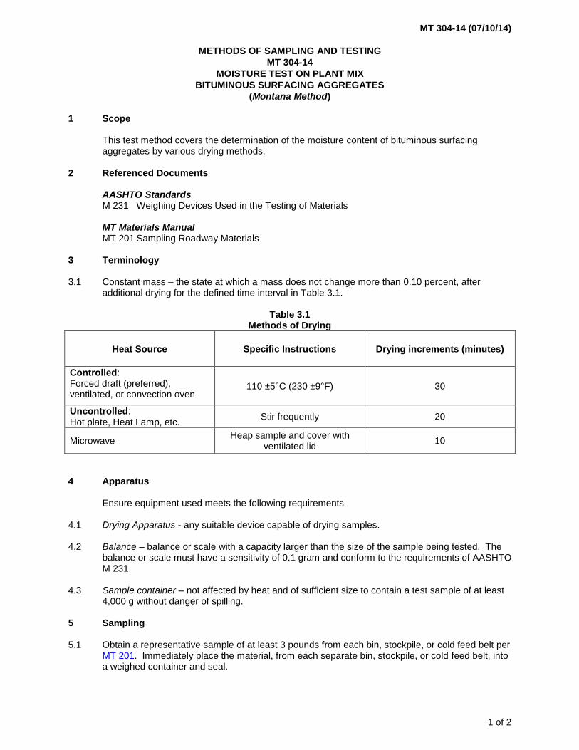
MT 201 Sampling Roadway Materials 3 Terminology 3.1 Constant mass – the state at which a mass does not change more than 0.10 percent, after
additional drying for the defined time interval in Table 3.1.
Table 3.1 Methods of Drying
Heat Source Specific Instructions Drying increments (minutes)
Controlled: Forced draft (preferred), ventilated, or convection oven
110 ±5°C (230 ±9°F) 30
Uncontrolled: Hot plate, Heat Lamp, etc.
Stir frequently 20
Microwave Heap sample and cover with
ventilated lid 10
4 Apparatus
Ensure equipment used meets the following requirements 4.1 Drying Apparatus - any suitable device capable of drying samples. 4.2 Balance – balance or scale with a capacity larger than the size of the sample being tested. The
balance or scale must have a sensitivity of 0.1 gram and conform to the requirements of AASHTO M 231.
4.3 Sample container – not affected by heat and of sufficient size to contain a test sample of at least
4,000 g without danger of spilling. 5 Sampling 5.1 Obtain a representative sample of at least 3 pounds from each bin, stockpile, or cold feed belt per
MT 201. Immediately place the material, from each separate bin, stockpile, or cold feed belt, into a weighed container and seal.

MT 304-14 (07/10/14)
2 of 2
6 Procedure 6.1 After weighing the container with aggregate, transfer the material to drying pans and dry to
constant mass in an approved manner. Stir the sample occasionally to facilitate drying. 6.2 Reweigh sample and container when the sample has been dried to constant mass. Note 1 – Perform moisture testing on mixes showing the following properties:
• Foaming on the surface of the coarse aggregate particles
• Excessive slumping of the mix in the truck
• Condensed water dripping from the truck box
• Bubbles or blisters forming on the surface immediately behind the paver Ordinarily these conditions will not develop if the moisture content is below approximately 2 percent. 7 Calculations 7.1 Compute the moisture content of each sample of the aggregate using the following formula:
𝑀 = (𝑊−𝐷
𝐷−𝐶) × 100
where: M = percent of moisture W = wt. of wet sample and container D = wt. of dry sample and container C = wt. of container 7.2 Compute the composite moisture content of the total aggregate according to the following
example:
Aggregate Size Fraction of Job Mix
Moisture Content, Percent
3/4" to 3/8" 0.20 x 2.00 = 0.40 3/8" to No. 10 0.40 x 1.00 = 0.40 Passing No. 10 0.40 x 0.50 = 0.20
Composite Moisture Content
= 1.00
8 Reporting 8.1 Report the moisture content to the nearest 0.10 percent.
MT 305-09 (05/15/09)
METHODS OF SAMPLING AND TESTING
MT 305-09
METHOD OF TEST FOR VOLUME SWELL OF BITUMINOUS MIXTURES
(MONTANA TEST METHOD) 1 Scope 1.1 This test method provides for the determination of the maximum volume swell of compacted
aggregates, soil, sand, or combination of mixtures passing the 10 Mesh (2.0 mm) sieve and stabilized with bituminous material.
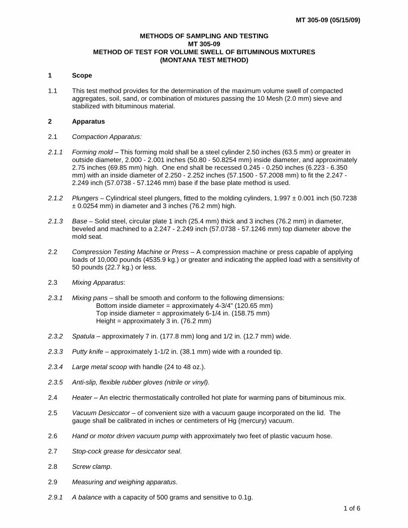
2 Apparatus 2.1 Compaction Apparatus: 2.1.1 Forming mold – This forming mold shall be a steel cylinder 2.50 inches (63.5 mm) or greater in
outside diameter, 2.000 - 2.001 inches (50.80 - 50.8254 mm) inside diameter, and approximately 2.75 inches (69.85 mm) high. One end shall be recessed 0.245 - 0.250 inches (6.223 - 6.350 mm) with an inside diameter of 2.250 - 2.252 inches (57.1500 - 57.2008 mm) to fit the 2.247 - 2.249 inch (57.0738 - 57.1246 mm) base if the base plate method is used.
2.1.2 Plungers – Cylindrical steel plungers, fitted to the molding cylinders, 1.997 ± 0.001 inch (50.7238
± 0.0254 mm) in diameter and 3 inches (76.2 mm) high. 2.1.3 Base – Solid steel, circular plate 1 inch (25.4 mm) thick and 3 inches (76.2 mm) in diameter,
beveled and machined to a 2.247 - 2.249 inch (57.0738 - 57.1246 mm) top diameter above the mold seat.
2.2 Compression Testing Machine or Press – A compression machine or press capable of applying
loads of 10,000 pounds (4535.9 kg.) or greater and indicating the applied load with a sensitivity of 50 pounds (22.7 kg.) or less.
2.3 Mixing Apparatus: 2.3.1 Mixing pans – shall be smooth and conform to the following dimensions:
Bottom inside diameter = approximately 4-3/4" (120.65 mm) Top inside diameter = approximately 6-1/4 in. (158.75 mm) Height = approximately 3 in. (76.2 mm)
2.3.2 Spatula – approximately 7 in. (177.8 mm) long and 1/2 in. (12.7 mm) wide. 2.3.3 Putty knife – approximately 1-1/2 in. (38.1 mm) wide with a rounded tip. 2.3.4 Large metal scoop with handle (24 to 48 oz.). 2.3.5 Anti-slip, flexible rubber gloves (nitrile or vinyl). 2.4 Heater – An electric thermostatically controlled hot plate for warming pans of bituminous mix. 2.5 Vacuum Desiccator – of convenient size with a vacuum gauge incorporated on the lid. The
gauge shall be calibrated in inches or centimeters of Hg (mercury) vacuum. 2.6 Hand or motor driven vacuum pump with approximately two feet of plastic vacuum hose. 2.7 Stop-cock grease for desiccator seal. 2.8 Screw clamp. 2.9 Measuring and weighing apparatus. 2.9.1 A balance with a capacity of 500 grams and sensitive to 0.1g.
1 of 6

MT 305-09 (05/15/09)
2.9.2 A measuring device that is accurately calibrated and equipped to determine heights and
diameters of test specimens to the nearest 0.01 cm. 2.9.3 Mercury Displacement Cup – A glass or plastic cup with flat ground edge of convenient size to
contain test specimens for mercury displacement measurement. 2.9.4 Glass dish approximately 10 x 6 x 2 in. (254 x 152.4 x 50.8 mm) 2.9.5 Porcelain pan approximately 15 x 10 x 2-1/2 in. (381 x 254 x 63.5 mm) 2.10 Drying Oven – A thermostatically controlled drying oven capable of maintaining a temperature of
140± 5°F (60 ± 3°C) 2.11 A 4 mesh (4.75 mm) and a 10 mesh (2.0 mm) sieve. 2.12 Thermometers, beakers, and a 100 ml, glass, graduated cylinder with intervals of 1.0 mm. 2.13 Pulverizing Apparatus – Either a mortar and rubber covered pestle or a mechanical device
consisting of a power-driven rubber covered mallet suitable for breaking up the aggregations of soil particles without reducing the size of the individual grains.
3 Materials 3.1 Distilled water with a pH of approximately 7. (Tap water is satisfactory if it does not interfere
chemically with the test.) 3.2 Bituminous material - 200/300 Pen A.C. 3.2.1 200/300 Pen A.C. should be replaced with new asphalt at the beginning of each construction
season. 3.3 Mercury 3.3.1 Mercury (Hg) is a poison and can be absorbed through the respiratory tract, the intestinal tract or
through unbroken skin. Mercury is a cumulative poison and is a very volatile element. Dangerous levels are readily attained in the air at 77ºF (25ºC). Tests involving the use of Mercury should be performed under conditions of adequate ventilation. A fume hood is recommended for large numbers of samples or where the test is to be carried out frequently over extended periods of time. Protective gloves should be worn under conditions here skin contact with mercury may occur.
3.3.2 This test procedure does not purport to address all of the safety concerns, if any, associated with
its use. It is the responsibility of the user of this test procedure to establish appropriate safety and health practices and determine the applicability of regulatory limitation prior to use.
4 Preparation of Aggregate 4.1 A representative sample of the 10 mesh (2.00 mm) material as described in AASHTO R 58 shall
be prepared. The sample shall be large enough to produce approximately 400 grams of minus 10 mesh (2.00 mm) material at the conclusion of the pulverizing procedure.
2 of 6

MT 305-09 (05/15/09)
5 Volume Swell Procedure
The caliper method will be used to test all volume swell samples. If the caliper method yields a volume swell of 8.0 or greater than a sample will be submitted to either the Helena Materials Lab or the Billings District Lab for testing using the mercury method. The mercury method will only be performed in the Helena Materials Lab or the Billings District Lab. Porous briquettes that may entrap mercury shall be measured with calipers only.
5.1 Volume Swell Procedure – Caliper Method 5.1.1 Warm the 200/300 pen asphalt cement for mixing to approximately 250 ± 15ºF (121 ± 8ºC). 5.1.2 Stabilize the hot plate at 425ºF to 475 ºF (218ºC to 246ºC). 5.1.3 Stir the sample prepared in paragraph 4 with a spatula and transfer a 100 gram sample to the
weighing scoop. Use the spatula to obtain a uniform discharge and to pull material from the bottom of the sample container when transferring the material. If desired, the material may be preheated in an oven 230 ± 9ºF (110 ± 5ºC).
5.1.4 Transfer the 100 gram sample from the weighing scoop to the mixing pan, stir with a putty knife
and shake the material to one side of the mixing pan. 5.1.5 Place the mixing pan and sample on the balance and add 6.5 grams of 200/300 Pen A.C., do not
pour asphalt on material; place the pan back on the hot plate. 5.1.6 When asphalt starts to flow into the sample, start mixing rapidly with a putty knife while shaking
the mixing pan close to the hot plate. Avoid overheating the mix, as evidenced by smoking as-phalt. Mix and shake until a thorough mixture is obtained. See Note 1.
Note 1 – In the case of material having poor adhesion, the larger particles will only be slightly coated. Do
not add more asphalt. Mix and shake until maximum coverage is obtained. 5.1.7 Pour the mixture from the mixing pan into a small scoop. Pour the mixture from the scoop into the
assembled mold using the spatula to assist in obtaining a uniform discharge from the scoop. Insert the top plunger with a twist and a light tamp to seat firmly. Place the mold in the compression machine and at a uniform rate increase the load to a total of 6280 pounds in no less than 15 seconds. Maintain the maximum load for one minute and release. Remove the base plate with a twisting motion and mark the briquette in the mold with a wax crayon, applying light pressure.
5.1.8 After removing the base plate with a twisting motion and marking the briquette, turn the assembly
upside down. Place the sleeve on top of the forming mold and using the jack apply, pressure to the sleeve and top plunger. This will push the briquette and top plunger up into the sleeve. See Note 2. Cool and cure the briquette for three hours at room temperature.
Note 2 – If the briquettes tend to stick to the mold or plungers, preheat mold to 140ºF (60ºC). 5.1.9 Wipe the forming mold, base plate and plungers clean with a suitable solvent and dry with a cloth
before forming each briquette. 5.1.10 Measure and record the height and radius of the cured briquette. To obtain the height of the
specimen, measure and record the height (flats of the specimen) in four locations. Measurements should be taken at 90 degree intervals. Average the four measurements and use the average height for the calculations. To obtain the radius of the specimen, measure and record the diameter of the specimen (sides) in four locations. Measurements should be taken at 45 degree intervals. Average the four measurements and divide by 2 to obtain the average radius. Use the average radius for the calculations. Refer to Paragraph 6.1.2 (calculations) to determine the volume of the cured briquette.
5.1.11 Check the vacuum equipment for leaks before any briquettes are put into the desiccator.
3 of 6

MT 305-09 (05/15/09)
5.1.12 Fill the vacuum desiccator with distilled water and allow to stabilize at room temperature.
Completely submerge the briquette in the distilled water and seal the top. See Note 3. Note 3 – A perforated tray is supplied for a second layer of briquettes. 5.1.13 Subject the briquette to 8 inches (20.3 cm) of mercury vacuum for one hour. The 8 inches of
vacuum will be applied within the desiccator in not less than one minute. The vacuum is maintained for one hour and released gradually to avoid pressure shock to the briquettes.
5.1.14 Keep the briquette completely submerged in the distilled water at room temperature for an
additional 23 hours. If necessary to transfer to another container of distilled water, wait 15 minutes after releasing pressure before effecting transfer.
5.1.15 Remove the briquette, blot the excess water and weigh. Measure and record the height and
radius of the swollen briquette. To obtain the height of the specimen, measure and record the height (flats of the specimen) in four locations. Measurements should be taken at 90 degree intervals. Average the four measurements and use the average height for the calculations. To obtain the radius of the specimen, measure and record the diameter of the specimen (sides) in four locations. Measurements should be taken at 45 degree intervals. Average the four measurements and divide by 2 to obtain the average radius. Use the average radius for the calculations. Refer to Paragraph 6.1.2 (calculations) to determine the volume of the cured briquette and the percent of volume swell. In no event will the briquette be allowed to set for more than ten minutes before measuring is completed. The sides of the briquette will be squeezed for recording condition of the briquette such as hard, firm, soft, soft and cracked, or disintegrated. Refer to paragraph 6.1.1 (calculations) to determine the percent of volume swell. (See Note 4)
Note 4 – The test specimen shall be measured immediately after excess water is blotted off the
specimen. When measuring with calipers, take four measurements on the sides of the specimen and four measurements on the flats of the specimen at 90 degree intervals and record. The average of the recordings will be used for the calculation.
5.2 Volume Swell Procedure – Mercury Method
The Helena Materials Lab and the Billings District Lab are the only labs that will be performing volume swell testing using Mercury. A designated set of testing apparatus will be used to test using mercury (such as a Vacuum Desiccator designated for mercury method samples). The mercury method briquettes will be stored in a labeled container with a lid. The desiccator disposal water will also be stored in a labeled container with a lid. The waste products will be stored near the mercury method equipment and when a container of approximately five gallons is collected, Environmental Services will be contacted for disposal.
5.2.1 Warm the 200/300 Pen Asphalt Cement for mixing to approximately 250 ± 15ºF (121± 8ºC). 5.2.2 Stabilize the hot plate at 425 to 475ºF (218 to 246ºC). 5.2.3 Stir the sample prepared in paragraph 4 with a spatula and transfer a 100 gram sample to the
weighing scoop. Use the spatula to obtain a uniform discharge and to pull material from the bottom of the sample container when transferring the material. If desired, the material may be preheated in an oven 230± 9ºF (110± 5ºC).
5.2.4 Transfer the 100 gram sample from the weighing scoop to the mixing pan, stir with a putty knife
and shake the material to one side of the mixing pan. 5.2.5 Place the mixing pan and sample on the balance and add 6.5 grams of 200/300 Pen A.C., do not
pour asphalt on material; place the pan back on the hot plate.
4 of 6

MT 305-09 (05/15/09)
5.2.6 When asphalt starts to flow into the sample, start mixing rapidly with a putty knife while shaking
the mixing pan close to the hot plate. Avoid overheating the mix, as evidenced by smoking as-phalt. Mix and shake until a thorough mixture is obtained. See Note 1.
5.2.7 Pour the mixture from the mixing pan into a small scoop. Pour the mixture from the scoop into
the assembled mold using the spatula to assist in obtaining a uniform discharge from the scoop. Insert the top plunger with a twist and a light tamp to seat firmly. Place the mold in the compression machine and at a uniform rate increase the load to a total of 6280 pounds in no less than 15 seconds. Maintain the maximum load for one minute and release. Remove the base plate with a twisting motion and mark the briquette in the mold with a wax crayon, applying light pressure.
5.2.8 After removing the base plate with a twisting motion and marking the briquette, turn the assembly
upside down. Place the sleeve on top of the forming mold and using the jack apply, pressure to the sleeve and top plunger. This will push the briquette and top plunger up into the sleeve. See Note 2. Cool and cure the briquette for three hours at room temperature.
5.2.9 Wipe the forming mold, base plate and plungers clean with a suitable solvent and dry with a cloth
before forming each briquette. 5.2.10 Weigh the cup filled with mercury and record the weight (W1). Place the cured briquette in the
cup and allow the mercury to displace by pressing the plastic plate flatly, squarely and firmly down on the specimens top surface until the plate is seated on the top rim on the cup and the excess mercury is fully displaced. Remove the cured briquette. Weigh and record the weight of the mercury and the cup minus the weight of the mercury lost due to immersion of the cured briquette (W2). Wear Rubber exam gloves at all times when while testing with mercury.
5.2.11 Check the vacuum equipment for leaks before any briquettes are put into the desiccator. 5.2.12 Fill the vacuum desiccator with distilled water and allow to stabilize at room temperature.
Completely submerge the briquette in the distilled water and seal the top. See Note 3. 5.2.13 Subject the briquette to 8 inches (20.3 cm) of mercury vacuum for one hour. The 8 inches of
vacuum will be applied within the desiccator in not less than 1 minute. The vacuum is maintained for one hour and released gradually to avoid pressure shock to the briquettes.
5.2.14 Keep the briquette completely submerged in the distilled water at room temperature for an
additional 23 hours. If necessary to transfer to another container of distilled water, wait 15 minutes after releasing pressure before transfer.
5.2.15 Remove the briquette and blot the excess water. Place the swollen briquette in the mercury cup
and allow the briquette to displace the mercury by pressing the plastic plate flatly, squarely and firmly down on the specimen’s top surface until the plate is seated on the top rim on the cup and the excess mercury is fully displaced. Weigh and record the weight of the mercury and the cup minus the weight of the mercury lost due to immersion of the swollen briquette (W3). In no event will the briquette be allowed to set for more than ten minutes before weighing is completed. The sides of the briquette will be squeezed for recording condition of the briquette such as hard, firm, soft, soft and cracked, or disintegrated. Refer to paragraph 6.1.2 (calculations) to determine the percent of volume swell. See Note 5.
Note 5 – The test specimen shall be weighed immediately after excess water is blotted off the specimen.
If the specimen is allowed to set for any amount of time, the specimen will dry out and shrink giving erroneous swell results.
5 of 6

MT 305-09 (05/15/09)
6 Calculation 6.1 The volume swell, expressed as a percentage can be calculated by either of the two following
methods. 6.1.1 Percent Volume Swell by Caliper Method V = πr2
h where: V = volume of specimen π = 3.1416 r = radius of specimen h = height of specimen and
100
112 xV
VVS −=
where: S = volume swell, percent V1 = volume of specimen before immersion, by caliper V2 = volume of specimen after immersion 6.1.2 Percent Volume Swell by Mercury Method
100
2132 xWW
WWS−−=
where: S = volume swell, percent W1 = weight of cup filled with mercury W2 = weight of mercury and cup minus mercury lost because of immersion of cured briquette W3 = weight of mercury and cup minus mercury lost because of immersion of swollen briquette 7 Report 7.1 The report shall consist of the following: 7.1.1 Percent of Volume Swell, 7.1.2 Condition of specimen.
6 of 6

MT 310-17 (12/31/17)
1 of 6
METHODS OF SAMPLING AND TESTING
MT 310-17
METHOD OF DETERMINING THE MACRO-TEXTURE OF A PAVEMENT SURFACE
(Modified ASTM E965)
1 Scope
1.1 This method describes the procedures for determining the average macro-texture depth of micro-
milled concrete surfaces and micro-milled and cold-milled plant mix surfaces.
1.2 This standard does not purport to address all the safety concerns associated with its use. It is the
responsibility of the user of this procedure to establish appropriate safety and health practices
and to determine the applicability of regulatory limitations prior to use.
2 Reference Documents
AASHTO
M 247 Glass Beads Used in Traffic Paints
ASTM
E965 Measuring Pavement Macrotexture Depth Using a Volumetric Technique
MT Materials Manual
MT 606 Procedure for Selecting Sampling locations by random sampling technique
METHOD A – COLD-MILLED PLANT MIX SURFACES
3 Apparatus
3.1 Filler – Type 1 glass beads in accordance with AASHTO M 247.
3.2 Spreader – A flat, stiff, hard disk made from methyl methacrylate (Plexiglas) with a thickness of
0.5 ± 0.1 inch, diameter of 8 ± 2 inch and a round handle affixed in the center
3.3 Graduate – A conical or cylindrical shape graduate, 250 ml capacity
3.4 Brushes – A stiff wire brush and a soft bristle brush
3.5 Container – A small sample container with a secure and easily removable cover, at least 200 ml
capacity
3.6 Screen – A shield to protect the test area location from air turbulence created from wind or traffic.
4 Test Material Preparation
4.1 Prepare one sample container for each test area location.
4.1.1 Fill the graduate with 200 ± 2 ml of filler.
4.1.2 Gently tap the side of the graduate to level the surface of the filler.
4.1.3 Place the measured volume of filler in the container.
4.1.4 Label the container with type and quantity of filler.

MT 310-17 (12/31/17)
2 of 6
5 Procedure
5.1 Test Area
5.1.1 Randomly select a test area location(s) on the milled pavement surface in accordance with
MT 606.
5.1.2 Inspect the test area location and ensure it is a dry, homogeneous site, free of unique or localized
features such as cracks, joints, stripping and patching.
5.1.3 If localized features are present, move up-station at the same transverse offset until a suitable
site is found.
5.1.4 Gently clean an area of about 1 foot by 1 foot for the test area location using the stiff wire brush to
remove any residue, debris or loosely bonded material. Be careful not to dislodge bonded
material. After using the stiff wire brush, gently brush the test area location with the soft bristle
brush to remove any remaining debris.
5.1.5 Place the screen on the milled pavement surface to protect the test area location from air
turbulence.
5.2 Test Measurement
5.2.1 Hold the container with filler no more than 4 inches above the pavement at the test area location.
5.2.2 Pour the measured volume of filler from the container onto the milled pavement surface in a
conical pile.
5.2.3 Place the spreader lightly on top of the conical pile of filler being careful not to compact the filler.
5.2.4 Move the spreader in a slow, circular motion to disperse the filler in a circular area and to create a
defined crest around the perimeter.
5.2.5 Continue spreading the filler until it is well dispersed and the spreader rides on top of the high
points of the milled pavement surface.
5.2.6 Measure and record the diameter of the circular area four times, at intervals of 45º and to the
nearest 0.1 inch, as shown in Figure 1.
5.2.7 Measure the diameter of the circular area from the top (crest) of the slope on one side, through
the center, and to the top (crest) of the slope on the other side of the circular area.
Figure 1: Typical Measuring Pattern

MT 310-17 (12/31/17)
3 of 6
5.2.8 Calculate the average diameter of the circular area covered by the filler (Equation 9.1).
5.2.9 Determine the macro-texture thickness of the milled pavement surface by using the cross
reference table in Section 9.3 below.
5.3 Remove the filler material from the location using the soft bristle brush and repeat Subsection 5.2
two more times.
METHOD B – MICRO-MILLED CONCRETE AND PLANT MIX SURFACES
6 Apparatus
6.1 Filler – Type 1 glass beads in accordance with AASHTO M 247
6.2 Spreader – A flat, stiff hard disk with a thickness of 1.0 ± 0.5 inch, diameter of 4 ± 2 inch
6.3 Graduate – A conical or cylindrical shape graduate, 250 ml capacity
6.4 Brushes – A stiff wire brush and a soft bristle brush
6.5 Container – A small sample container with a secure and easily removable cover, at least 50 ml
capacity
6.6 Screen – A shield used to protect the test area from air turbulence created from wind or traffic
7 Test Material Preparation
7.1 Prepare one sample container for each test area location.
7.1.1 Fill the graduate with 25 ± 2 ml of filler.
7.1.2 Gently tap the side of the graduate to level the surface of the filler.
7.1.3 Place the measured volume of filler in the container.
7.1.4 Label the container with type and quantity of filler.
8 Procedure
8.1 Test Area
8.1.1 Randomly determine a test area location on the milled pavement surface in accordance with
MT 606.
8.1.2 Gently clean an area of about 1 foot by 1 foot for the test area location using the stiff wire brush to
remove any, residue, debris or loosely bonded material. Be careful not to dislodge bonded
material. After using the stiff wire brush, gently brush the test area location with the soft bristle
brush to remove any remaining debris.
8.1.3 Place the screen on the milled pavement surface to protect the test area location from air
turbulence.

MT 310-17 (12/31/17)
4 of 6
8.2 Test Measurement
8.2.1 Hold the container with filler no more than 4 inches above the pavement at the test area location.
8.2.2 Pour the measured volume of filler from the container onto the milled pavement surface into a
conical pile.
8.2.3 Place the spreader lightly on top of the conical pile of filler being careful not to compact the filler.
8.2.4 Move the spreader in a slow, circular motion to disperse the filler in a circular area and to create a
defined crest around the perimeter.
8.2.5 Continue spreading the filler until it is well dispersed and the spreader rides on top of the high
points of the pavement surface.
8.2.6 Measure and record the diameter of the circular area four times, at intervals of 45º and to the
nearest 0.1 inch, as shown in Figure 1.
8.2.7 Calculate the average diameter of the circular area covered by the filler (Equation 9.1).
8.2.8 Determine the macro-texture thickness of the milled pavement surface by using the cross
reference table in Section 9.4 below.
8.3 Repeat Subsection 8.2 two more times.
8.4 Remove the filler material from the locations and properly dispose of the material.
9 Calculations
9.1 For each test area location, perform the following calculations.
9.1.1 Calculate the average diameter of the circular area covered by the filler.
𝐷𝑎 = (𝐷1 + 𝐷2 + 𝐷3 + 𝐷4)
4
Where:
Da = Average diameter of the filler area, inches
D1, D2, D3, D4 = Diameters of the filler area, inches
9.1.2 Calculate the area of the circle covered by the filler in square inches (in2).
𝐴 = 𝜋𝐷𝑎2
4
9.1.3 Calculate the volume of filler in cubic inches (in3).
𝑉(𝑖𝑛3) = 𝑉(𝑚𝑙)
16.387 𝑚𝑙/𝑖𝑛3
9.1.4 Calculate Macro-texture Depth (inches):
𝐷𝑒𝑝𝑡ℎ =𝑉(𝑖𝑛3)
𝐴(𝑖𝑛2)

MT 310-17 (12/31/17)
5 of 6
9.1.5 Example:
Da = 8.0 inches
Area = π Da2/4 = π 8.02/4 = 50.265 in2
Volume of filler = 25 ml
Convert ml to cubic inches = 25/16.387 = 1.525 in3
Depth = V(in3)/A(in2) = 1.525 in3/50.265 in2 = 0.030 in.
9.2 Calculate the Average Texture Depth (ATD)
9.2.1 Add the three (3) individual macro-texture depth results and divide by three.
9.2.2 Report the ATD to the nearest 0.001 inches.
9.3 Macro-Texture Thickness Based on 200 ml of Filler and Average Diameter
Average
Diameter
(inches)
Macrotexture
Thickness
(inches)
Average
Diameter
(inches)
Macrotexture
Thickness
(inches)
Average
Diameter
(inches)
Macrotexture
Thickness
(inches) 7.1 0.308 8.8 0.201 10.5 0.141
7.2 0.300 8.9 0.196 10.6 0.138
7.3 0.292 9.0 0.192 10.7 0.136
7.4 0.284 9.1 0.188 10.8 0.133
7.5 0.276 9.2 0.184 10.9 0.131
7.6 0.269 9.3 0.180 11.0 0.128
7.7 0.262 9.4 0.176 11.1 0.126
7.8 0.255 9.5 0.172 11.2 0.124
7.9 0.249 9.6 0.169 11.3 0.122
8.0 0.243 9.7 0.165 11.4 0.120
8.1 0.237 9.8 0.162 11.5 0.117
8.2 0.231 9.9 0.159 11.6 0.115
8.3 0.226 10.0 0.155 11.7 0.113
8.4 0.220 10.1 0.152 11.8 0.112
8.5 0.215 10.2 0.149 11.9 0.110
8.6 0.210 10.3 0.146 12.0 0.108
8.7 0.205 10.4 0.144 12.1 0.106
MT 310-17 (12/31/17)
6 of 6
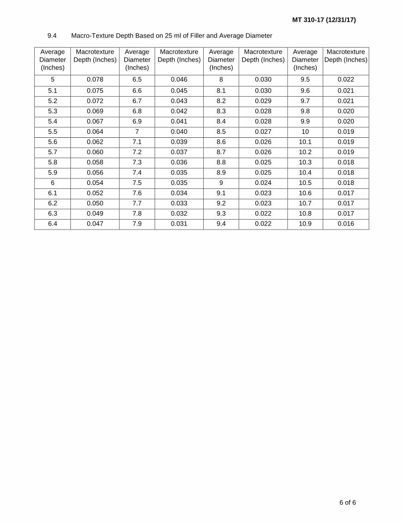
9.4 Macro-Texture Depth Based on 25 ml of Filler and Average Diameter
Average
Diameter
(Inches)
Macrotexture
Depth (Inches)
Average
Diameter
(Inches)
Macrotexture
Depth (Inches)
Average
Diameter
(Inches)
Macrotexture
Depth (Inches)
Average
Diameter
(Inches)
Macrotexture
Depth (Inches)
5 0.078 6.5 0.046 8 0.030 9.5 0.022
5.1 0.075 6.6 0.045 8.1 0.030 9.6 0.021
5.2 0.072 6.7 0.043 8.2 0.029 9.7 0.021
5.3 0.069 6.8 0.042 8.3 0.028 9.8 0.020
5.4 0.067 6.9 0.041 8.4 0.028 9.9 0.020
5.5 0.064 7 0.040 8.5 0.027 10 0.019
5.6 0.062 7.1 0.039 8.6 0.026 10.1 0.019
5.7 0.060 7.2 0.037 8.7 0.026 10.2 0.019
5.8 0.058 7.3 0.036 8.8 0.025 10.3 0.018
5.9 0.056 7.4 0.035 8.9 0.025 10.4 0.018
6 0.054 7.5 0.035 9 0.024 10.5 0.018
6.1 0.052 7.6 0.034 9.1 0.023 10.6 0.017
6.2 0.050 7.7 0.033 9.2 0.023 10.7 0.017
6.3 0.049 7.8 0.032 9.3 0.022 10.8 0.017
6.4 0.047 7.9 0.031 9.4 0.022 10.9 0.016

MT 316-04 (06/01/04)
1 of 5
METHOD OF SAMPLING AND TESTING
MT 316-04
METHOD OF SAMPLING RECYCLED PAVEMENT
AND FIELD CONTROL OF RECYCLE PAVING 1 General 1.1 This method is divided into four sections which are as follows: 1.2 Section A: Sampling pavement for Cold Recycling 1.3 Section B: Field Control of Cold Recycle Paving 1.4 Section C: Sampling Pavement for Hot Recycling 1.5 Section D: Field Control of Hot Recycle Paving
Each section of this method is to be used specifically for its respective purpose related to recycle paving.
SECTION A 2 Sampling Pavement for Cold Recycling 2.1 Scope 2.2 This section describes the procedure for sampling roadways for cold mix recycling. The first
portion describes sampling procedures for design information to determine if recycling is possible. The second portion describes sampling procedures for mix design purposes.
3 Procedure 3.1 Preliminary Sampling for Proposed Recycled Pavement 3.1.1 The project should be divided into at least three areas from which milled or cored samples are
obtained. A minimum of three representative sample locations should be visually selected in each area. Samples weighing approximately sixty pounds and representative of the lifts to be recycled should be obtained from each location. If maintenance patches or other intermittent treatments occur within the area, the locations that samples were taken should be recorded and the samples properly labeled. The proposed depth for recycling the pavement should be recorded.
3.1.2 Sampling a Cold Recycled Pavement for Mix Design: Milled Sampling 3.1.2.1 The project should be divided into at least three areas from which samples are obtained. A
minimum of three locations should be used for each area of sampling. Submit approximately one hundred pounds of milled plant mix from each location. Three core samples should be taken to correspond with each milled area. The core samples should be placed into sealed containers at the job site so that in-place moisture contents may be determined.
3.1.3 Submitting Samples 3.1.3.1 Samples from different locations are to be kept separate and submitted to the Materials Bureau
for testing. Pertinent information such as locations at which samples were taken and depth to which milling was performed should be submitted with the samples.

MT 316-04 (06/01/04)
2 of 5
SECTION B 4 Field Control of Cold Recycle Paving 4.1 Scope 4.1.1 This section describes the procedure for field control of cold recycle paving. The test procedure
utilizes standard 50 blow Marshall specimens. The Marshall specimens will be fabricated at the job site and then transported to the Materials bureau for compression testing.
4.1.2 Material should be secured from either the feed hopper of the laydown machine or the windrow,
depending on the paving operation. Enough material (at least 25 lbs.) should be obtained for both the molding of briquettes and moisture determination.
5 Procedure 5.1 Determination of Moisture Content 5.1.1 For moisture determination, a representative sample of 2000 grams shall be weighed and placed
in a 140°F oven. 5.1.2 The sample shall be weighed at intervals with weight losses recorded until a stabilized condition
is achieved. A moisture loss of less than 1.0 gram in one hour should be considered a stabilized condition. Moisture content may be determined by:
% 100%
5.2 Briquette Fabrication 5.2.1 Apparatus 5.2.1.1 Scoops 5.2.1.2 Thermometer, - 50° to 150°F 5.2.1.3 Balance – 2 kg. Capacity for weighing batch samples and briquettes 5.2.1.4 Mixing spoons 5.2.1.5 Spatulas 5.2.1.6 Standard Marshall compaction pedestal – with molds and compaction hammer 5.2.1.7 Extrusion jack 5.2.1.8 Gloves and marking crayons 5.2.1.9 Pans for holding and warming specimens 5.2.1.10 Oven – capable of maintaining 140°F ±5°F 6 Preparation of Test Specimens 6.1 Prepare three specimens for each test. 6.2 Thoroughly clean molds and hammer face. Place paper disk in bottom of molds. Warm molds and
hammer to remove chill.

MT 316-04 (06/01/04)
3 of 5
6.3 Weigh out individual briquette samples. It is recommended that a trial briquette, approximately 1140 grams, be molded initially to determine height. Weight of material should then be adjusted to produce 2-1/2” ±0.05” specimens.
6.4 Warm individual specimens in 140°F oven for two hours. Note: This process has been found to
develop a density of mix equal to the roller compaction on the roadway. 6.5 Mold briquettes using standard Marshall procedures (i.e., 50 blows applied to each face).
6.6 Curing specimens in molds for up to 24 hours before extruding may be necessary if distortion occurs at an earlier extrusion time. Molds should be placed on their sides to permit equal ventilation of both ends (remove paper disks).
6.7 Carefully extrude specimens from molds. 6.8 If, when extruded, briquettes are sufficiently strong to enable handling, proceed to weigh in air,
weigh in water and weigh saturated surface dry. 6.9 If, when extruded, briquettes are too tender to handle, curing will be required until they can be
handled. The bulk specific gravities may then be determined. Bulk specific gravity is calculated as follows:
6.9 Once bulk specific gravities have been determined, carefully transport the specimens to the
Materials Lab for compression testing. 6.10 Report the specific gravities that were measured and the location represented by the samples.
The samples must be protectively wrapped for shipping and they must be numbered sequentially to maintain control of their origin and history.
7 Utilization of Final Record Samples 7.1 The final record pavement core samples taken in accordance with MT 602 are designated for
research. As soon as possible, these should be sent to the Materials Bureau, accompanied by Form No. 31. The location and sample number are to be entered on the form and the wrapped cores are to be sequentially numbered.
SECTION C 8 Sampling Pavement for Hot Mix recycling 8.1 Scope 8.1.2 This section describes the procedure for sampling roadways for hot mix recycling. The first
portion describes sampling procedures for design information to determine if recycling is possible. The second portion describes sampling procedures for mix design purposes.
9 Procedure 9.1 Preliminary Sampling for Proposed Recycled Pavement:

MT 316-04 (06/01/04)
4 of 5
9.1.2 The project should be divided into at least three areas from which milled or cored samples are obtained. A minimum of three representative sample locations should be visually selected in each area. Samples weighing approximately sixty pounds and representative of the lifts to be recycled should be obtained from each location. If maintenance patches or other intermittent treatments occur within the area, the locations that samples were taken from should be recorded and the samples properly labeled. The proposed depth for recycling the pavement should be recorded.
To complete assessment of a potentially recyclable pavement, submit information about sources of aggregate used on the original project. In addition, send a minimum of 350 pounds of material to the Materials Bureau from a source which may be used as a virgin aggregate in the recycle mix.
10 Sampling a Hot Recycled Pavement for Mix Design 10.1 Milled Sampling: 10.1.1 The project should be divided into at least three areas from which samples are obtained. A
minimum of three locations should be used for each area of sampling. Submit approximately one hundred pounds of milled plant mix from each location. Three core samples should be taken to correspond with each milled area.
11 Stockpile Sampling 11.1 Stockpiles of crushed reclaimed plant mix shall be sampled in accordance with MT 201,
paragraph 10. Note – Stockpile sampling requires particular care to avoid segregation. Samples should be taken from a
near vertical face and should be secured by reducing the sample to 300-pounds by the quartering method or with a sample splitter. Due to the time required t extract and analyze the reclaimed plant mix, samples should be submitted as soon as one-third of the reclaimed mat stockpile has been produced.
11.2 To complete the mix design, 350 pounds of aggregate from the stockpiles of virgin aggregate,
along with the appropriate forms, are required. The samples and documentation may be submitted when, in the judgment of the Project Manager, they are representative of the material to be incorporated into the recycled plant mix.
SECTION D 12 Field Control of Hot Recycle Paving 12.1 Scope 12.1.2 This section describes the procedure for field control of hot recycle paving. 13 Procedure 13.1 The crushed reclaimed mate shall be sampled in accordance with MT 201, paragraph 11:
“Production sample shall be taken not less than every four hours. The sample shall be sieved and the percentage of oversize recorded. One sample of approximately 15 pounds shall be taken and submitted to the Materials Bureau every three days.”
13.2 The aggregate incorporated into the mix shall be subject to all of the controls of a normal plant
mix operation. The output of the plant will be subjected t field control Marshall testing with the same frequency as a conventional mix.
13.3 Monitors of established production of recycled plant mix shall be taken the first three days and the
first day of every week thereafter or until otherwise informed by the Materials Bureau.

MT 316-04 (06/01/04)
5 of 5
13.4 The samples shall be placed in a new double paper bag with completed form No 98 inserted between the sacks to keep it clean. The bag should be securely tied and marked as to sample number, stationing, lane and lift. This same information shall be placed on each Daily Plant Mix Report. Several of these paper bags can be packed into a sample sack for transmittal to the laboratory. Care should be taken to see that no movement is possible, or broken bags and mixed samples will result.
14 Utilization of Final Record Samples 14.1 The final record pavement core samples taken in accordance with MT 602 are designated for
research. As soon as possible, these should be sent to the Materials Bureau, accompanied by Form No. 31. The location and sample number are to be entered on the form and the wrapped cores are to be sequentially numbered.

MT 319-17 (09/30/17)
1 of 6
METHODS OF SAMPLING AND TESTING
MT 319-17
DETERMINING THE ASPHALT BINDER CONTENT
OF PLANT MIX SURFACING (PMS) BY THE IGNITION METHOD
(Modified AASHTO T 308) 1 Scope 1.1 This test method covers the determination of asphalt binder content of Plant Mix Surfacing (PMS)
mixtures by ignition at temperatures that reach the flashpoint of the binder in a furnace. The means of specimen heating may be the convection method or the direct infrared (IR) irradiation method.
1.2 The values in metric units are to be regarded as the standard. 1.3 This standard may involve hazardous materials, operations, and equipment. This standard does
not purport to address all of the safety problems associated with its use. It is the responsibility of the user of this standard to consult and establish appropriate safety and health practices and determine the applicability of regulatory limitations prior to use.
2 Referenced Documents
AASHTO M 231 Weighing Devices Used in the Testing of Materials R 47 Reducing Samples of Hot Mix Asphalt (HMA) to Testing Size T 308 Determining the Asphalt Binder Content of Hot Mix Asphalt (HMA) by the Ignition Method T 329 Moisture Content of Hot Mix Asphalt (HMA)Asphalt Mixtures by Oven Method MT Materials Manual MT 202 Sieve Analysis of Fine and Coarse Aggregates MT 303 Sampling Bituminous Paving Mixtures MT 320 Mechanical Analysis of Aggregate Recovered from Ignition Oven Burn
3 Summary of Test Method 3.1 The asphalt binder in the paving mixture is ignited using the furnace equipment applicable to the
particular method. The asphalt binder content is calculated as the difference between the initial mass of the PMS and the mass of the residual aggregate. The asphalt content is expressed as mass percent of moisture-free mixture. This method may be affected by the type of aggregate in the mixture. Accordingly, to optimize accuracy, establish correction factors for asphalt binder and aggregate by testing a set of correction factor specimens for each type of PMS.
4 Significance and Use 4.1 This method can be used for quantitative determinations of asphalt binder content and gradation
in PMS mixtures and pavement specimens for quality control, specification acceptance, and mixture evaluation studies. This method does not require the use of solvents. Use aggregate obtained by this test method for gradation analysis according to MT 320.
5 Apparatus
Ensure equipment used meets the following requirements: 5.1 Ignition furnace – A forced air ignition furnace that heats the specimen by either convection
method or direct IR irradiation method. Use a convection-type furnace capable of maintaining a temperature at 578°C (1072°F). Use a furnace containing an internal balance thermally isolated from the furnace chamber and accurate to 0.1 g. The balance must be capable of weighing a 3500 gram specimen in addition to the specimen baskets. A data collection system is included so that the weight can be automatically determined and displayed during the test. The furnace has a built in computer program to calculate change in mass of the specimen and provide for the input of a correction factor. The furnace chamber and basket dimensions must be adequate to

MT 319-17 (09/30/17)
2 of 6
accommodate a specimen size of up to 3500 grams. The furnace provides an audible alarm and indicator light when the specimen mass loss does not exceed 0.01 percent of the total specimen mass for three consecutive minutes. The furnace door is equipped so that the door cannot be opened during the ignition test. The furnace must be vented into a hood or to the outside. The furnace is equipped with a fan capable of pulling the air through the furnace to expedite the test and to reduce the escape of smoke into the laboratory.
5.2 Specimen basket(s) – of appropriate size that allows the specimens to be thinly spread and
allows air to flow through and around the specimen particles. Ensure sets with 2 or more baskets are nested. Completely enclose the specimen with screen mesh, perforated stainless steel plate, or other suitable material.
Note 1 – Screen mesh or other suitable material with maximum and minimum opening of 2.36 mm (No. 8)
and 600 microns (No. 30), respectively, has been found to perform well. 5.3 Catch Pan – of sufficient size to hold the specimen basket(s) so that aggregate particles and
melting asphalt binder falling through the screen mesh are caught. 5.4 Oven – capable of maintaining mix design compaction temperature. 5.5 Balance – of sufficient capacity and conforming to the requirements of AASHTO M 231, Class
G2, for weighing specimen in basket(s). 5.6 Safety Equipment – face shield, high temperature gloves, a heat resistant surface capable of
withstanding 650°C (1202°F) and a protective cage capable of surrounding the specimen baskets during the cooling period.
5.7 Miscellaneous Equipment – a pan larger than the specimen basket(s) for transferring specimen
after ignition; spatulas, bowls, wire brushes, and other manufacturer’s equipment. 6 Sampling 6.1 Obtain samples of freshly produced PMS in accordance with MT 303. 6.2 Obtain the test specimen by splitting a sample taken in accordance with AASHTO R 47. 6.3 If the mixture is not sufficiently soft to separate with a spatula or trowel, place it in a large flat pan
or glass dish in an oven (conventional or microwave). Heat the specimen to separate. Excessive heat may cause asphalt drain down or oxidation to occur, altering the results.
6.4 The size of the test specimen is governed by the nominal-maximum aggregate size of the PMS
and must conform to the mass requirement shown in Table 1. Ensure the specimen is no more than 400 grams greater than the minimum recommended specimen mass.
Note 2 – Large specimens of fine mixes tend to result in incomplete ignition of asphalt.
Table 1—Mass Requirements
Nominal Max Agg Size, mm Sieve Size
Min Mass of Specimen,
g
4.75 No. 4 1200 9.5 ⅜ in. 1200 12.5 ½ in. 2000 19.0 ¾ in. 2000 25.0 1 in. 3000 37.5 1½ in. 4000
MT 319-17 (09/30/17)
3 of 6
7 Test Procedure 7.1 Test Initiation: 7.1.1 For the convection-type furnace, preheat the ignition furnace to 538°C (1000°F) or as determined
in ANNEX A4.1. Manually record the furnace temperature (set point) prior to the initiation of the test if the furnace does not record automatically.
7.1.2 For the direct IR irradiation-type furnace, preheat furnace to 420°C (788°F) or manufacturer’s
recommendation. Use the same burn profile as used during the correction factor determination. 7.2 Determine the moisture content of the specimen according to AASHTO T 329 at the beginning
and middle of each production day and as needed. 7.3 Apply the correction factor for the specific mix to be tested as determined in ANNEX A1 in the
ignition furnace. 7.4 Weigh and record the mass of the specimen basket(s) and catch pan (with guards in place) to the
nearest 0.1 gram. 7.5 Prepare the specimen as described in Section 6. Place the specimen basket(s) in the catch pan.
Evenly distribute the specimen in the specimen basket(s), taking care to keep the material away from the edges of the basket. Use a spatula or trowel to level the specimen.
7.6 Weigh and record the total mass of the specimen, basket(s), catch pan, and basket guards.
Calculate and record the initial mass of the specimen (total mass minus the mass of the specimen basket assembly).
7.7 Input the initial mass of the specimen to 0.1 gram for direct IR irradiation-type furnace or 1 gram
for convection-type furnace into the ignition furnace controller. Verify that the correct mass has been entered.
7.8 Open the chamber door and place the specimen basket assembly in the furnace, carefully
positioning the specimen basket assembly so it is not in contact with the furnace walls. Close the chamber door, and verify that the specimen mass (including the basket assembly) displayed on the furnace scale equals the total mass recorded in Section 7.6 within ± 5 grams. (Note 4). An indication that the specimen basket assembly is contacting the furnace wall is a difference greater than 5 g or failure of the furnace scale to stabilize.
Initiate the test by pressing the start/stop button. This operation will lock the specimen chamber and start the combustion blower.
Note 3 – The furnace temperature will drop below the set point when the door is opened, but will recover
with the door closed and when ignition occurs. Specimen ignition typically increases the temperature well above the set point, depending on specimen size and asphalt binder content.
Note 4 – The weights obtained from external weighing take precedence over those obtained from the
internal balance. 7.9 Allow the test to continue until the stable light and audible alarm indicate the test is complete (the
change in mass does not exceed 0.01 percent for three consecutive minutes). Press the start/stop button. This will unlock the specimen chamber door.
7.10 Open the chamber door, remove the specimen basket assembly, allow specimen to cool to room
temperature and weigh. During cooling, ensure specimen basket assembly is protected from contaminates.

MT 319-17 (09/30/17)
4 of 6
7.11 Calculate the corrected asphalt binder content (percent) from the external weighing according to the following equation:
MCCfX
Mi
MfMiPb
100,%
Where: Pb = the measured (corrected) asphalt binder content, percent Mi = the total mass of the PMS specimen prior to ignition, g Mf = the total mass of aggregate remaining after the ignition, g Cf = the correction factor, percent by mass of PMS specimen MC = the moisture content of the PMS
8 Extraction of Residual Aggregate for Gradation 8.1 Cool the contents of the specimen baskets to room temperature prior to performing the gradation
analysis. Empty the contents of the baskets into a flat pan, being careful to capture all the material. Use a small wire sieve brush to ensure that any residual fines are removed from the baskets and catch pan.
8.2 Weigh the specimen and perform the gradation analysis according to MT 320. 9 Report 9.1 Report the corrected asphalt binder content to the nearest 0.01%, correction factor,
temperature compensation factor (if applicable), total percent loss, specimen mass and moisture content (if determined).

MT 319-17 (09/30/17)
5 of 6
ANNEX A1 Correction Factors A1.1 Asphalt binder content results may be affected by the type of aggregate in the mixture and the
ignition furnace. Accordingly, to optimize accuracy, establish a correction factor by testing a set of correction factor specimens for each type of PMS. Perform this procedure before any acceptance testing is completed. Repeat the process for determining a correction factor each time there is a new or transferred PMS design. Determine a unique correction factor for each ignition furnace in the location where testing is to be performed.
A1.2 Asphalt binder correction factor – Certain aggregate types may result in unusually high correction
factors (greater than 1.0 percent). Such mixes must be corrected and tested at a lower temperature, as described below. Determine a unique asphalt binder correction factor for each ignition furnace in the location where testing will be performed.
A1.3 Aggregate correction factor – Due to potential aggregate breakdown during the ignition process,
determine a unique aggregate correction factor for each ignition furnace in the location where testing will be performed when the following conditions occur: aggregates that have a proven history of excessive breakdown; or aggregates are from an unknown source.
A2 Correction Factor Procedure A2.1 According to the requirements of Section 6, prepare a minimum of four correction specimens at
the job mix formula design asphalt content and gradation using only virgin material in a buttered bowl. Sample aggregate used for the correction factor specimens from stockpiled material produced and designated for use on the candidate project. An additional “blank” (aggregate only) specimen is provided for aggregate gradation comparison according to MT 320. The washed gradation must fall within the mix design tolerances.
A2.2 Place the freshly mixed specimens directly in the specimen baskets assembly. If allowed to cool,
heat the specimens in a conventional oven to compaction temperature. Do not preheat the specimen baskets assembly.
A2.3 Test the specimens in accordance with Sections 7 and 8. A2.4 After burning the appropriate number of calibration specimens, determine the measured asphalt
binder contents for each specimen by calculation or from the printed tickets. A2.5 If the difference between the measured asphalt binder contents of the 2 specimens exceeds 0.15
percent, repeat the 2 tests and, from the 4 tests, discard the high and low results. Determine the correction factor from the 2 remaining results. Calculate the difference between the actual and measured asphalt binder contents for each specimen. The correction factor is the average of the differences expressed in percent by weight of the asphalt mixture.
A3 Correction Factor Ignition Oven Temperature Adjustment A3.1 For the convection-type furnace, if the correction factor exceeds 1.0 percent, lower the test
temperature to 482 ± 5°C (900 ± 8°F) and repeat test. Use the correction factor obtained at 482°C (900 ± 8°F) even if it exceeds 1.0 percent.
A3.2 For the direct irradiation-type furnace, use Option 2 burn profile for most materials. Option 1 is
designed for very soft aggregate (such as dolomites) that typically require a large aggregate correction factor (greater than 1%). Option 2 is designed for specimens that may not burn completely using the DEFAULT burn profile and is appropriate for most of Montana aggregates.

MT 319-17 (09/30/17)
6 of 6
A4 Procedure Temperature A4.1 For the convection-type furnace, the temperature for testing PMS specimens in Section 7.1.1 is
the same temperature selected for testing mixture correction specimens. A4.2 For the direct IR irradiation-type furnace, the burn profile for testing PMS specimens in Section
7.1.2 is the same burn profile selected for testing mixture correction specimens. A5 Aggregate Correction Factor A5.1 Perform a gradation analysis on the residual aggregate in accordance with MT 320. Utilize the
results to develop an aggregate correction factor. Calculate and report to the nearest 0.1 percent. A5.2 From the gradation results, subtract the percent passing for each sieve for each specimen from
the percent passing each sieve of the “blank” specimen gradation results from Section A2.1. A5.3 Determine the average difference for the 2 values. If the difference for a single sieve exceeds the
allowable difference for that sieve as listed in Table A1, apply aggregate gradation correction factors (equal to the resultant average differences) for all sieves, to all acceptance gradation test results determined by MT 320, prior to final rounding and reporting. If the 0.075-mm (No. 200) sieve is the only sieve outside the limits in Table A1, apply the aggregate correction factor to only the 0.075-mm (No. 200) sieve.
Table A1 – Permitted Sieving Difference
Sieve Size Allowable Difference
Sizes larger or equal to 2.36 mm (No. 8) ±5.0%
Sizes larger than 0.075 mm (No. 200) and smaller than 2.36 mm (No. 8)
±3.0%
Sizes 0.075 mm (No. 200) and smaller ±0.5%
A6 Burn Oven Worksheet

MT 320-17 (06/30/17)
1 of 1
METHODS OF SAMPLING AND TESTING
MT 320-17
MECHANICAL ANALYSIS OF AGGREGATE RECOVERED FROM IGNITION OVEN BURN
(Modified AASHTO T 30)
MT 320 is identical to AASHTO T 30 except for the following stipulations: 1. Replace Table 1 with the following:
Table 1 – Maximum Allowable Mass of Material Retained on a Sieve
Screen Size
8-inch (203 mm)
Diameter Screen
12-inch (304.8 mm)
Diameter Screen
Maximum
Grams
Maximum
Pounds
Maximum
Grams
Maximum
Pounds
1 ¼-inch (31.75 mm) 3821.9 8.4
1-inch (25.0 mm) 3057.5 6.7
¾-inch (19.0 mm) 2598.9 5.7
⅝-inch (16.0 mm) 2293.2 5.1
½-inch (12.5 mm) 1987.4 4.4
⅜-inch (9.5 mm) 223.0 2.7
No. 4 (4.75 mm) 318 0.7
No. 8 (2.36 mm) 194 0.4 436.5 0.9
No. 10 (2.00 mm) 194 0.4 436.5 0.9
No. 16 (1.18 mm) 194 0.4 436.5 0.9
No. 30 (0.600 mm) 194 0.4 436.5 0.9
No. 40 (0.425 mm) 194 0.4 436.5 0.9
No. 50 (0.300 mm) 194 0.4 436.5 0.9
No. 80 (0.180 mm) 194 0.4 436.5 0.9
No. 100 (0.150 mm) 194 0.4 436.5 0.9
No. 200 (0.075 mm) 194 0.4 436.5 0.9
Note – If the sample is overloading screens, split or quarter the sample in accordance with MT 607,
Procedure for Reducing Field Samples of Aggregate to Testing Size. Grade each part of the sample
separately and combine the weights to obtain a representative gradation. Use the following table to
determine if screens are overloaded.


MT 321-17 (06/30/17)
1 of 4
METHOD OF SAMPLING AND TESTING
MT 321-17
DETERMINING THEORETICAL MAXIMUM SPECIFIC GRAVITY
OF BITUMINOUS PAVING MIXTURES - "RICE GRAVITY"
(MODIFIED AASHTO T 209)
1 Scope 1.1 This test method covers the determination of theoretical maximum specific gravity (commonly
referred to as Rice Gravity) of un-compacted bituminous paving mixtures. 2 Referenced Documents
AASHTO T 209 Theoretical Maximum Specific Gravity and Density of Hot Mix Asphalt (HMA) MT Materials Manual MT 303 Sampling Bituminous Paving Mixtures MT 309 Splitting Samples of Plant Mix Surfacing to Testing Size MT 325 Determining Moisture Content of Bituminous Mixtures or Aggregate Using Microwave
Ovens 3 Terminology 3.1 Residual pressure (as employed by this test method) – the pressure in a vacuum vessel when
vacuum is applied. 3.2 Specific gravity (as determined by this test method) – the ratio of a given mass of material at 77°F
(25°C) to the mass of an equal volume of water at the same temperature. 4 Significance and Use 4.1 The theoretical maximum specific gravities of bituminous paving mixtures are basic properties
whose values are influenced by the composition of the mixtures and types and amounts of aggregates and asphalt materials.
4.2 These properties are used to calculate percent air voids in compacted bituminous paving
mixtures. 4.3 These properties provide target values for the compaction of bituminous paving mixtures. 4.4 These properties are essential when calculating the amount of asphalt binder absorbed by the
internal porosity of the individual aggregate particles in bituminous paving mixtures. 5 Apparatus Ensure equipment used meets the following requirements: 5.1 Balance – Capacity of 16,000 g sensitive to 0.1 g, to allow the maximum specific gravity of the
un-compacted mix to be calculated to the nearest thousandth (0.001 g). 5.2 Container – 4000 mL volumetric flask. Ensure the flask, with a proper cover (see Note 1), is
sufficiently strong to withstand a partial vacuum. Confirm the top surfaces of all containers are smooth and substantially plane.
Note 1 – MDT uses a glass capillary stopper.

MT 321-17 (06/30/17)
2 of 4
5.3 Vacuum System 5.3.1 Vacuum Pump – Motor driven vacuum pump, capable of maintaining at least 25 mm of Hg of
vacuum. The pump is used for removing air from the flask through the vacuum. 5.3.2 Vacuum Apparatus - rubber stopper with a hose connection to connect the volumetric flask to
vacuum pump. 5.3.3 Vacuum Measurement Device – Residual pressure manometer or vacuum gauge connected
directly to the vacuum vessel and capable of measuring residual pressure down to 25 mm of Hg or less.
5.4 Water Bath – Water bath capable of maintaining constant temperature of 77 ± 1ºF (25 ± 0.6ºC) to
fill the 4000 mL flask. 5.5 Thermometer – Liquid-in-glass thermometer accurate to 0.5°C (1°F). 6 Sampling 6.1 Obtain field samples in accordance with MT 303. Split field samples in accordance with MT 309. 6.2 Meet the sample size requirements in Table 1.
Table 1 – Minimum Sample Sizes
Nominal Maximum Aggregate Size Minimum Sample Size
1" (25 mm) 2500 g (5.50 lb)
3/4" (19 mm) 2000 g (4.40 lb)
1/2" (12.5 mm) 1500 g (3.30 lb)
3/8" (9.5 mm) 1000 g (2.20 lb)
No. 4 (4.75 mm) 500 g (1.10 lb)
7 Standardization of Flasks 7.1 At the beginning of PMS production, the volumetric flask and glass capillary stopper are
standardized to accurately determine the mass of water at 77 ± 1ºF (25 ± 0.6ºC) in the flask. 7.1.1 Fill the flask with water. Gently place the stopper in the flask ensuring proper seating. Ensure all
air has been removed from the flask. Remove flask from water bath. Carefully towel dry the outside of the flask and stopper area. Weigh the flask with stopper and record the mass. Designate this mass as E1, E2, or E3.
7.1.2 Remove the stopper and decant a portion of the water back into the bath. Repeat Section 7.2 two
(2) more times. 7.1.3 Record the average of the flask standardization masses (See section 9.1). Designate this
average mass as E. 7.2 Check standardization daily when testing and re-standardize as needed or when there is a
change in tester, equipment, or when adding additional water for the day’s testing. Keep the equipment clean and free from any accumulation that would change the mass if the volume standardization is to remain constant. Do not subject glass vessels to vacuum if they are scratched or damaged.
8 Procedure 8.1 Obtain a sample size in accordance with section 6.2, Table 1.

MT 321-17 (06/30/17)
3 of 4
8.2 Separate the particles of the sample, taking care not to fracture the mineral particles so that the fine aggregate portion is not larger than ¼ inch.
8.3 The sample may be heated at mix design compaction temperature if necessary to facilitate the
breakup of the sample. 8.4 Cool the sample to approximately 77ºF. 8.5 Remove flask from water bath containing enough water at 77ºF to cover the sample by
approximately 1 inch, towel dry the outside of the flask, and place on the scale. Record the mass of the flask and water, then tare the scale.
8.6 Add the sample to the tared flask ensuring both the sample and the flask are at
77 ± 2ºF (25 ± 0.6ºC). Weigh to the nearest 0.1g. Designate the mass of the sample as D. 8.7 Wet the mouth of the flask and seat the vacuum apparatus on the flask, to ensure a proper seal
between the flask and the vacuum apparatus. Turn on the vacuum pump to remove entrapped air by subjecting the contents to a partial vacuum of 27.5 ± 2.5 Hg mm gauge pressure for 15 ± 2 minutes (See Note 2). Agitate the container and contents either continuously by mechanical device or manually by vigorous shaking at intervals of about 2 minutes.
Note 2 – The time the sample is under vacuum does not begin until the proper gauge pressure has been
reached. 8.8 Turn off the vacuum pump, slowly open the release valve to allow the pressure to normalize, then
remove the vacuum apparatus. 8.9 Fill the flask with water from the water bath (77 ± 2ºF). Gently place the stopper in the flask
ensuring proper seating and taking care not to introduce air into the sample. Place the flask and contents in the water bath and bring the contents to a temperature of 77 ± 2ºF within 10 ± 1 min after completing the vacuum procedure. Check the temperature of the contents with the thermometer.
8.10 Remove flask from water bath. Carefully towel dry the outside of the flask and stopper area.
Determine the mass of the flask filled with contents. Designate the mass of flask with water and sample as C.
9 Calculations 9.1 Calculate the average of the flask standardization masses as follows:
𝐸 = (𝐸1 + 𝐸2 + 𝐸3
3)
Where: E = averaged mass of standardized flask, designated as mass of flask E1 = 1st flask standardization mass E2 = 2nd flask standardization mass E3 = 3rd flask standardization mass 9.2 Calculate the mass of the sample (dry mass) and mass of standardized flask:
𝐹 = 𝐷 + 𝐸 Where: F = mass of the sample (dry mass) and mass of standardized flask D = mass of the sample (dry mass) E = mass of flask

MT 321-17 (06/30/17)
4 of 4
9.3 Calculate the volume of the sample as follows:
𝐺 = 𝐹 − 𝐶
Where: G = Volume of sample F = mass of sample (dry mass) and flask (equation 9.2)
C = mass of the standardized flask with contents (water and saturated sample after vacuum procedure)
9.4 Calculate the “Rice Gravity” of the sample as follows:
𝑅 = 𝐷
𝐺
Where: R = Gmm = theoretical maximum specific gravity of the mixture, “Rice Gravity” D = mass of the sample (dry mass) G = volume of sample (equation 9.3)
10 Report 10.1 Report the theoretical maximum specific gravity of the mixture (Rice Gravity) to the nearest
thousandth (0.001).

MT 322-04 (10/19/04)
1 of 2
METHODS OF SAMPLING AND TESTING
MT 322-04
METHOD OF DETERMINING THE PERCENT OF ADHESION
OF BITUMINOUS MATERIALS TO AGGREGATE
(Montana Method)
1 Scope
1.1 This test is intended to evaluate the resistance of a bituminized mixture to its bituminous film
removal by water. 2 Apparatus
2.1 Drying oven - capable of maintaining a temperature of 248º F (120º C).
2.2 Electric hot plate
2.3 Various mixing pans
2.4 Putty knife
2.5 Balance - with a capacity of 500 grams
2.6 ¼" wire screen
2.7 ½ gallon can
2.8 Water
2.9 “Red Devil" or equal paint shaker
3 Preparation of Sample
3.1 The proposed aggregate is mixed with bituminous materials, which may be Asphalt Cement or
Liquid Asphalt, or Emulsified Asphalt. The preparation of the sample, depending upon the type of bituminous materials, is as follows:
3.2 Asphalt Cement or Liquid Asphalt
3.2.1 Approximately 150 grams of plus ¼" aggregate and a sufficient quantity of the appropriate
bituminous material are heated in separate containers in an oven at 248 ºF (120 ºC). 3.2.2 After heating, the aggregate is mixed on a hot plate with just enough bituminous material to
thoroughly coat the aggregate surfaces. Avoid overheating the mix, as evidenced by smoking asphalt. A metal pan and putty knife are used to accomplish the mixing. The mixture is oven cured at 250 ºF (121 ºC) for one hour, then stirred and left to cool at room temperature.
3.3 Emulsified Asphalt
3.3.1 The test procedure varies somewhat at the preliminary stage when an emulsified asphalt is used.
Add a sufficient quantity of the appropriate emulsion to approximately 150 grams of dry, cool, plus ¼" aggregate and stir until the sample is completely covered. Excess emulsion is drained off on an elevated 4 Mesh wire screen. The mixture is oven cured at 250 ºF (121 ºC) for a period of one hour. If CRS-2 is used, the aggregate must be pre-wetted.

MT 322-04 (10/19/04)
2 of 2
4 Procedure
4.1 After the aggregate-bituminous mixture has cooled or cured for the prescribed time, it is removed
from the mixing pan or draining screen with a putty knife. Note – In order to facilitate removal, the mixture may be removed from the mixing pan or draining screen
after the receptacle has been heated on a hot plate for approximately three seconds. 4.2 The mixture is then immersed in a half-gallon can containing one quart of water at 49 to 73 ºF (15
to 25 ºC) for twenty-four hours. 4.3 At the end of the soaking period, the mixture is shaken in a "Red Devil" or other approved paint
shaker for five minutes, after which it is carefully washed to remove any loose bituminous material, and placed on a doubled layer of paper toweling. The sample is spread evenly over an area approximately five inches in diameter so that the paper is not visible through the sample.
5 Evaluation
5.1 Evaluation of adhesion is made only after the aggregate is thoroughly dry. A visual estimate of
the proportion of the surfaces remaining coated with bituminous material is made and the results expressed as percent adhesion.
MT 328-14 (07/29/14)
1 of 1
METHODS OF SAMPLING AND TESTING
MT 328-14
ESTABLISHING FIELD TARGET DENSITY
FOR PLANT MIX SURFACING DENSITY CONTROL 1 Scope 1.1 This test method is the procedure for establishing the field target density for compaction control of
bituminous mixtures. 2 Referenced Documents MT Materials Manual
MT 321 Determining Theoretical Maximum Specific Gravity and Density of Bituminous Paving Mixtures – “Rice Gravity”
3 Procedure 3.1 Determine the maximum specific gravity of un-compacted bituminous paving mixtures in
accordance with MT 321. 3.2 When two (2) maximum specific gravities of field samples have been determined using MT 321,
average the results. Use the average for the field target Rice Gravity density. This target is effective retroactive to the start of plant mix production on the project.
Maintain documentation of the Theoretical Maximum Specific Gravity and Density of Bituminous Paving Mixtures (MT 321) to determine the target density and all changes during the contract.
3.3 When four (4) field Rice Gravities are completed, average the four (4) test values. If a change of
0.5 pound per cubic foot (8.0 kg per cubic meter) or greater is calculated change, to the new average Rice Gravity. This change is effective at the time the last sample was obtained.
Notify applicable Department personnel (e.g. Project Manager, Lab Supervisor, Lead Inspector) immediately of effective change with day, time and tonnage of the change.
3.4 As each additional field Rice Gravity is completed, add the results to the sum of the previous
three (3) gravities and compute an average. If a change of 0.5 pound per cubic foot (8.0 kg per cubic meter) or greater is calculated from the last field target density, change to the new average Rice Gravity. This change is effective at the time the last sample was obtained.


MT 329-04 (06/01/04)
METHODS OF SAMPLING AND TESTING
MT 329-04
PROCEDURE FOR EVALUATING
PLANT MIX SURFACING FAILURES 1 Scope 1.1 This method covers the step-by step procedure for evaluating a plant mix surfacing failure. The
procedure calls for reviewing the types of plant mix failures and method for rating the distressed areas.
1.2 After determining the type and extent of the failure, further investigational requirements will
include reviewing plant mix production records, visual analysis, deflection analysis, sampling analysis of plant mix, base and subgrade materials and surfacing design analysis. Based upon all the information and data gathered through this procedure, the causes, potential solutions and recommendations to correct the plant mix surfacing failures can be determined.
2 Visual Analysis 2.1 The first step in investigating a pavement failure is to perform a complete and comprehensive
visual analysis of the entire project emphasizing the distressed areas in question. 2.2 Determine the approximate milepost and/or stationing and length of each of the distressed areas.
The following is a list of pavement distress types and a rating system to be used for the distress.
PAVEMENT FAILURE RATING SYSTEM RATING
FAILURE TYPE Rutting
Light Moderate Severe
Rut Depth Rate of Rutting Lateral Movement Of Rut (Humping)
0-1/2” 0-1/8”/yr. None Visible
1/2 – 3/4” 1/8 – 3/8”/yr.
3/4” & Greater 3/8”/yr.& Greater Visible Bulge
Cracking Longitudinal Cracks In wheel paths (Load Associated)
Alligator or Block Cracking Tight
Alligator or Block Cracking Edges spaced – pieces loose or missing
*Stripping Some asphalt material stripped
**Cores **Cores
Ravelling Fines removed from surface.
1st layer coarse aggregate removed
Pavement removed through one or more lifts.
*Any stripping should be noted. **If the investigation requires plant mix cores, advanced stages of stripping will be determined at that time. Note – If dual wheel ruts exist, they should be noted. Measurements should always be taken in both
wheelpaths with a stringline stretched from centerline to the shoulder to obtain the measurements.
3 Report of Visual Analysis 3.1 A summary of the visual analysis should be written immediately after the investigation.
1 of 5

MT 329-04 (06/01/04)
3.2 The report should include date, reviewer, project termini, and detailed information concerning each distressed area. This information should include but not be limited to approximate milepost or station, length, width, relationship to centerline, lane and type of distress. Also, photographs of the typical distress on the project should be included. In addition to recording the types of pavement distress referenced above, record any other problems that are visible (drainage, terrain, frost problems, dips or swells, etc.). Based upon this visual analysis, the course of action and investigational requirements can be determined.
3.3 Copies of the report shall be sent to the District Engineer and the Materials Bureau Chief. 4 Deflection Analysis 4.1 After the visual analysis report has been evaluated, the second step of this procedure will
normally require Road Rater testing. The decision to have a Road Rate analysis will be determined based upon the visual analysis. When the decision has been made to use the Road Rater, the following are the steps that will be followed.
4.2 The Road Rater shall be used to determine the in-place strengths of each layer. An elastic
modulus for each layer will be determined from the roadway deflections. 4.2.1 Deflection tests will be taken at 200-800 foot intervals throughout problem areas to determine the
extent of the distress. In addition, the remainder of the project will be tested using the normal testing intervals (six tests per mile).
4.2.2 The deflection analysis will be reviewed for elastic modulus of each layer to determine the nature
and extent of the problem. The required design overlay thickness analysis will then be performed. 5 Investigation Requirements 5.1 Determine the investigational requirements depending on the type and extent of the plant mix
failure. The following is a list of the distress types and requirements for each:
Distress Type *Investigation Required
Cracking – Alligator (1)-(7)
Rutting & Shoving (1)-(7)
Stripping – Underlying Courses (1)-(7)
Ravelling – Surface (1),(3),(4)
Segregation (1),(3),(4)
6 Investigational Requirements 6.1 Physical Data (information already obtained)
Location Weather Extent of Failure Photos
6.2 Deflection Analysis (information already obtained)
Road Rater testing – evaluate good and bad areas of the project.
2 of 5

MT 329-04 (06/01/04)
6.3 Production Records (a review of construction reports) Note – When reviewing the reports listed below, look for any abnormalities. Example: The production records generated during construction should be reviewed to determine if any problems during construction can be related to the pavement failure. For example there may have been some density problems in the same area of the failure, late paving, etc.
Mix Design Plant Reports Marshall Tests Aggregate Tests Compaction Tests Monitor Samples Project Diaries
6.4 Core Samples – Plant mix core samples shall be obtained and tested as follows: Note – Lifts will be identified and tested separately.
Tests Thickness Density Rice Gravity A.C. Content Gradation HP-GPC Abson Extraction – AC Penetration Petrographic – Geology Other tests to be determined by the Materials Bureau at the time of testing.
7 Sampling In-Place Material
R Value Liquid Limit and Plastic Index Moisture Gradation Proctor
8 Traffic Data
Present ADL Accumulative ADL
9 Structural Properties
Gravel Equivalency – Surfacing Design 10 Samples and Testing Required 10.1 Samples shall be taken so that the following tests and procedures can be run to evaluate the
problem areas. The samples will be submitted to the Materials Bureau for testing unless otherwise specified.
3 of 5

MT 329-04 (06/01/04)
10.2 Plant Mix Surfacing Core Samples 10.2.1 Samples shall be taken of each plant mix layer with at least five 4” cores from a bad area, a
shoulder next to bad area, and good area. (See Figure 1 for sampling diagram.) If more than five distressed areas exist on a project, the minimum number of sample locations will be three if all distressed areas appear to be visually identical. If material or geological conditions change between distressed areas, each various condition shall be sampled. If the lifts are still intact they shall be separated using a coring saw if required. Each lift of plant mix shall be evaluated for:
Rice Gravity Density Thickness – Each core should be measured Extracted Gradation (MT 202) Extracted Percent Asphalt (AASHTO T 164) Abson Extraction – Asphalt Penetration HP-GPC Petrographic-Analysis
Figure 1. Sampling Diagram
PASSING LANE (X) (X) (X) (X) (X) DRIVING LANE FAILURE X X X X X SHOULDER * * * * * (X) – Samples from good area X – Samples within area of visible failure * - Samples within same paver pass but not visibly failed 10.3 Base and Subgrade 10.3.1 When obtaining samples of the base and subgrade materials, a minimum 3-by-3-foot area of
plant mix shall be taken in the wheel path at each location. This should allow for adequate testing and sampling of each lift of material.
10.3.2 In-place densities and moisture shall be obtained for each lift using a nuclear gauge. 10.3.3 In-place moisture samples shall be taken of each lift and immediately placed in a sealable plastic
sack. The sample size shall be a minimum of 1 lb. (450 grams). These samples shall then be oven dried to obtain a moisture content.
10.3.4 A minimum of two “R” value samples shall be taken from both the base and subgrade for a given
problem area. In addition, one sample per mile shall be taken for the remainder of the project. The sample size will be determined in accordance with MT 207.
10.3.5 Samples and size of each lift shall be taken immediately and placed in a sealable plastic bag for
soils classification (AASHTO M 145), plastic index (AASHTO T 90) and liquid limit (AASHTO T 89) in accordance with referenced procedures.
10.3.6 Samples of the base and subgrade shall be taken for a proctor test to establish the optimum
moisture and density. The sample size shall be determined in accordance with MT 230.
4 of 5

MT 329-04 (06/01/04)
11 Traffic Data 11.1 Traffic data will be requested from the Planning and Statistics Bureau by the Materials Bureau.
This data will be used by the Road Rater and Surfacing Design Sections to determine if any structural deficiencies exist. If the traffic section in the Planning Bureau feels traffic data may not reflect the true 18 Kip axle loads, a site specific investigation should be conducted by them.
12 Structural Analysis - Surfacing Design 12.1 The surfacing Design personnel will check the design of the problem area based on the new “R”
Values and the condition of the pavement structure in place. 13 Report 13.1 A summary of the sample tests and other investigational requirements will be submitted upon
completion of all testing of all testing and analysis.
5 of 5

MT 331-14 (07/29/14)
1 of 7
METHODS OF SAMPLING AND TESTING
MT 331-14
SAMPLING AND EVALUATING
STRIPPING PAVEMENTS
(Montana Method)
1 Scope 1.1 This test method describes the procedure for sampling cores. Cores are used to evaluate
existing structure, materials, pavement condition, lift thicknesses, and potential milling depth. 2 Sampling Procedure 2.1 4-Lane Roadway
Take a minimum of one (1) core per ½ mile of roadway in each direction. Alternate cores between the outside wheel path of the driving lane and the outside wheel path of passing lane. Pavement displaying a high extent or severity of cracking or raveling, rutting greater than 1/3 inch, and excessive patches, may require modification to the sampling frequency and location. If available, record the Global Positioning System (GPS) coordinates of core.
2.2 2-Lane Roadway
A minimum of one (1) core per ½ mile of roadway, taken in the outside wheel path and in alternating lanes. Pavement displaying a high extent or severity of cracking or raveling, rutting greater than 1/3 inch, and excessive patches, may require modification to the sampling frequency and location. If available, record the GPS coordinates of core.
Example: 3 Sample Containment 3.1 Bag the cores with the bagging system provided by the Department’s Helena Materials Bureau. If
possible, bag the core in the orientation it was extracted (directly from drill barrel). Keep field notes describing the appearance, location, and total depth of the core. Take pictures to accompany field notes. If a portion or portions of the core are rubble, describe the thickness of the rubble section and where the rubble portion was within the core. Submit the sample for stripping evaluation. Also describe the roadway condition and any other information that would be helpful in evaluating the cores and the in-place pavement.
4 Sample Identification and Submitting of Samples 4.1 Mark core with specimen number using a marker or grease pencil. Each core sample bag must
contain a tag including the Sample Record ID number and specimen number. Ensure the Sample Record contains the Sample ID number, specimen number, uniform project number (UPN), and project name if available, location (route number, station, mile post, lane, offset, and GPS), total depth drilled and total length of the core when bagged. Submit the cores to the Materials Bureau for evaluation. Include observations and comments in the Sample Record Remarks.
½-mile

MT 331-14 (07/29/14)
2 of 7
5 Evaluation of Cores 5.1 Evaluate the total core for stripping using the "control photographs" in Annex A. Split cores by
indirect tensile loading in a press and record maximum pressure needed to yield the core. Evaluate each lift or distinct layer of plant mix for stripping using the Core Rating Scale (Section 5.2).
5.2 Core Rating Scale
Core Rating Description
4 (good core) Face shiny, black, all aggregate particles coated
3 (moisture damaged) Loss of sheen, dull appearance, some smaller aggregate is uncoated
2 (stripping) In addition to moisture damage some large aggregate is not coated
1 (severely stripped) Most of the aggregate is so clean the colors of the rock are easily seen
0 (no core) Asphalt is mostly gone from all sizes of aggregate. The core has disintegrated.
6 Reporting Results 6.1 At the completion of the evaluation, test results consisting of the extent of stripping, and other test
information are entered into SiteManager by the Materials Bureau. Each lift or layer is evaluated for stripping in the report.
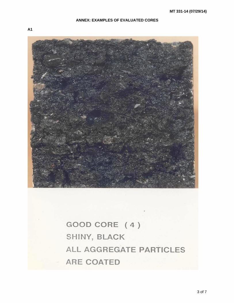
MT 331-14 (07/29/14)
3 of 7
ANNEX: EXAMPLES OF EVALUATED CORES
A1
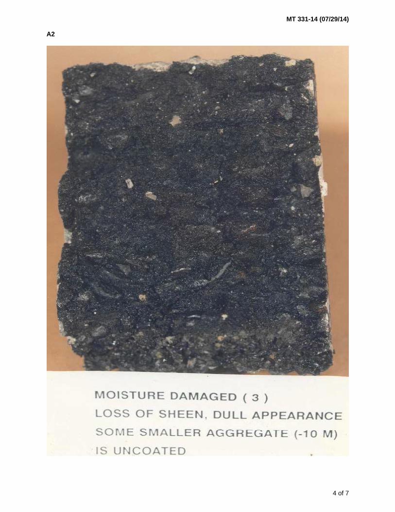
MT 331-14 (07/29/14)
4 of 7
A2
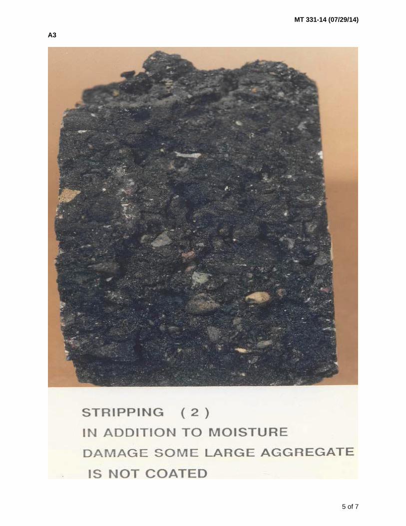
MT 331-14 (07/29/14)
5 of 7
A3
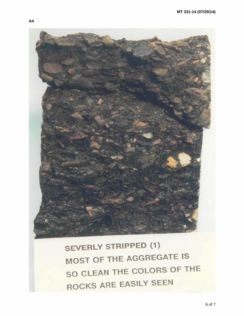
MT 331-14 (07/29/14)
6 of 7
A4
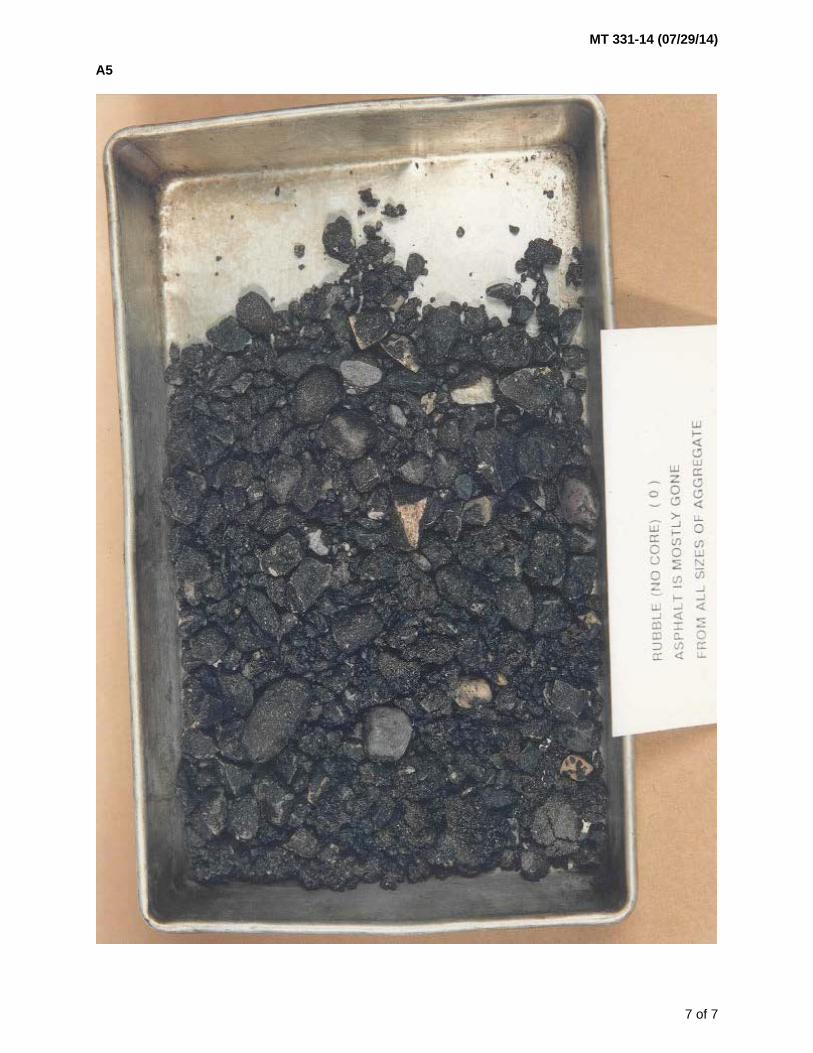
MT 331-14 (07/29/14)
7 of 7
A5


MT 332-17 (06/30/17)
1 of 2
METHOD OF SAMPLING AND TESTING
MT 332-17
GYRATORY COMPACTION OF BITUMINOUS MIXTURES
(Modified AASHTO T 312)
MT 332 is identical to AASHTO T 312 except for the following additions: 1. Section 11 – Include the following calculations. % Air Voids (Va)
𝑉𝑎 = 100 × (𝐺𝑚𝑚 − 𝐺𝑚𝑏
𝐺𝑚𝑚
)
Where: Gmm = Maximum specific gravity of paving mixture (Rice) Gmb = Bulk specific gravity of compacted mixture Record and round to the nearest 0.1% Voids in the Mineral Aggregate (VMA)
𝑉𝑀𝐴 = 100 - (𝐺𝑚𝑏(100 − 𝑃𝑠)
𝐺𝑠𝑏
)
Where: Gmb = Bulk specific gravity of compacted mixture Ps = Aggregate content, percent by total mass of mixture Gsb = Bulk specific gravity of aggregate Record and round to the nearest 0.1% Voids Filled with Asphalt (VFA)
𝑉𝐹𝐴 = 100 × (𝑉𝑀𝐴 − 𝑉𝑎
𝑉𝑀𝐴)
Record and round to the nearest 0.1% Dust/Asphalt Ratio
𝐷𝐴 = (𝑃200 − 1
𝑃𝑏
)
Where: DA = Dust to Asphalt Ratio, P200 = Aggregate content passing the 0.075mm sieve, the percent by mass of aggregate (MT
320) Pb = Asphalt Content, percent by total mass of mixture (MT 319) Record and round to the nearest 0.1%
Note – The Dust/Asphalt ratio is used during mix design and field production.

MT 332-17 (06/30/17)
2 of 2
Dust Proportion
𝐷𝑃 = (𝑃200 − 1
𝑃𝑏𝑒
)
Where: DP = Dust Proportion, P200 = Aggregate content passing the 0.075mm sieve, the percent by mass of aggregate
(MT 320) Pbe = Effective asphalt content, percent by total mass of mixture
Note – The Dust Proportion is used during mix design.
Effective Asphalt Content
𝑃𝑏𝑒= - (𝑃𝑠×𝐺𝑏) × (𝐺𝑠𝑒 − 𝐺𝑠𝑏
𝐺𝑠𝑒×𝐺𝑠𝑏
) + 𝑃𝑏
Where: Pbe = Effective asphalt content, percent by total mass of mixture Ps = Aggregate content, percent by total mass of mixture Gb = Specific gravity of asphalt Gse = Effective specific gravity of aggregate Gsb = Bulk specific gravity of aggregate Pb = Asphalt Content, percent by total mass of mixture Record and round to the nearest 0.1%.

MT 333-04 (06/01/04)
1 of 3
METHODS OF SAMPLING AND TESTING
MT 333-04
METHOD OF TEST FOR THE TORSIONAL RECOVERY OF
LATEX MODIFIED ASPHALT EMULSION RESIDUE
1 Scope 1.1 This test method provides an indication of the amount of elasticity that has been imparted to
asphalt by the addition of latex. The asphalt used in this test has been recovered from an emulsion.
2 Apparatus 2.1 Sample container – A flat-bottomed, cylindrical, seamless tin 55mm (2.17 inch) in diameter and
35 mm (1.38 inch) in depth. The container is commonly known as a 3-ounce ointment tin. 2.2 Disc and spider assembly – This assembly is shown in Figure 1. The disc is made of aluminum.
The spider assembly, bolt, and pointer are made of steel. 2.3 Wrench – A 9/16 inch open-end or box wrench. 2.4 Timer – A stopwatch, clock, or other timing device graduated in divisions of one second or less. 2.5 Scale – A paper scale, graduated in millimeters, at least 180 mm in length. 3 Procedure 3.1 Place the spider assembly on the container and adjust it so that it is centered, using the small
nuts on the arms of the spider to maintain the adjustment. Adjust the depth of the disc in the container so that the top of the disc will not be below the surface of the asphalt. Remove the spider assembly from the container. Construct two, centered spider assemblies and containers per test.
3.2 Obtain a latex modified asphalt residue sample by following the procedure outlined in
AASHTO T 59, Residue By Evaporation, sections 21 – 27. 3.3 Transfer a sufficient quantity of the hot residue into the sample container to fill it to within ½ to ¼
inch from the top of the container. Immediately place the previously centered spider assembly on the container and adjust the depth of the disc to bring the top of the disc level with the surface of the asphalt.
3.4 Place the two test assemblies in a 138°C (280°F) oven for ten minutes to allow air bubbles to
escape and the break the surface tension around the disc. Remove the assembly from the oven and allow cooling to room temperature for two hours.
3.5 Tape a paper scale around the container and mark the location of the pointer. Make another mark
180° form the pointer (halfway around the container). 3.6 Holding the container and spider assembly rigidly, place the wrench on the bolt head and turn the
bolt to the 180° reference mark and release immediately. The rotation should be done at a steady rate and be accomplished in approximately 5 seconds. Start the stopwatch when the bolt is released. Mark the location of the pointer on the scale when 30 seconds have elapsed, and again when 30 minutes have elapsed. Repeat the procedure with the second test assembly.

MT 333-04 (06/01/04)
2 of 3
4 Calculation and Report 4.1 The percent of recovery following deformation is calculated as follows:
2
∗ 100
Where: A = The arc on the container, measured in millimeters, between the mark made after 30 seconds
has elapsed, and the mark made after 30 minutes has elapsed. B = The circumference of the can, measured in millimeters.
4.2 Report the percent recovery as an average of the two tests.

MT 333-04 (06/01/04)
3 of 3


MT 334-17 (12/31/17)
1 of 4
METHOD OF SAMPLING AND TESTING
MT 334-17
HAMBURG WHEEL-TRACK TESTING
OF COMPACTED BITUMINOUS MIXTURES
(Modified AASHTO T 324) 1 Scope 1.1 This test method describes a procedure for testing the rutting and moisture-susceptibility of plant
mix surfacing (PMS) specimens in the Hamburg Wheel-Track Testing Device. 1.2 The method describes the testing of submerged, compacted PMS in a reciprocating rolling-wheel
device. This test provides information about the rate of permanent deformation from a moving, concentrated load. This procedure utilizes laboratory- or field laboratory-compacted specimens, field saw-cut slabs, or field cores.
1.3 The test method is used to determine the premature failure susceptibility of PMS due to
weakness in the aggregate structure, inadequate binder stiffness, or moisture damage. This test method measures the rut depth and number of passes to failure.
1.4 The specimens are submerged in temperature-controlled water during loading to evaluate the
potential for moisture damage effects. 2 Reference Documents
AASHTO T 166 Bulk Specific Gravity (Gmb) of Asphalt Mixtures Using Saturated Surface-Dry Specimens T 324 Hamburg Wheel-Track Testing of Compacted Asphalt Mixtures MT Materials Manual MT 303 Sampling Bituminous Paving Mixtures MT 321 Determining Theoretical Maximum Specific Gravity of Bituminous Paving Mixtures –
“Rice Gravity” MT 332 Gyratory Compaction of Bituminous Mixtures MT 335 Linear Kneading Compaction of Bituminous Mixtures Manufacturer’s Operation Manual For equipment used
3 Terminology 3.1 Specimen
Any of the following are considered specimens under this test method. 3.1.1 Laboratory-compacted slab 3.1.2 Two (2) paired laboratory-compacted gyratory pucks 3.1.3 Two (2) paired field laboratory-compacted gyratory pucks 3.1.4 Field core, 10” core or two (2) paired 6” cores 3.1.5 Field saw-cut slab 3.2 Mix Design Verification Test
A Mix Design Verification test will consist of evaluating two specimens with the Hamburg Wheel-Tracking Device and averaging the results.

MT 334-17 (12/31/17)
2 of 4
3.3 Field Production Verification Test
A Field Production Verification test will consist of the evaluation of one specimen with the Hamburg Wheel-Tracking Device.
4 Summary of Method 4.1 A laboratory- or field laboratory-compacted specimen of PMS, a core(s) taken from compacted
pavement, or a saw-cut slab specimen is repetitively loaded using a reciprocating steel wheel. The specimen is submerged in a temperature-controlled water bath at a temperature specified for the binder being used. The deformation of the specimen, caused by the wheel loading, is measured.
4.2 The impression is plotted as a function of the number of wheel passes. An abrupt increase in the
rate of deformation coincides with stripping of the asphalt binder from the aggregate in the PMS specimen.
5 Apparatus
Ensure equipment used meets the following requirements: 5.1 Hamburg Wheel-Track Testing Device – Electrically powered device capable of moving a steel
wheel with a diameter of 203.2 ± 2.0 mm (8 ± 0.08 in.) and width of 47 mm (1.85 in) over a test specimen. The load applied by the wheel is 705 ± 4.5 N (158 ± 1.0 lb.). The wheel load is maintained at ± 5% for the duration of the test excluding the cycles that are interrupted by stopping the process. The wheel reciprocates over the specimen, with the position varying sinusoidally over time. The wheel makes 52 ± 2 passes across the specimen per minute.
5.2 Temperature Control System – Water bath capable of controlling the temperature within ± 2.0ºC
over a range of 25 to 70ºC (77 to 158oF). This bath should have a mechanical circulating system to stabilize the water temperature.
5.3 Impression Measurement System – Linear Variable Differential Transducer (LVDT) device
capable of measuring the depth of the impression of the wheel within 0.5 mm, over a range of at least 0 to 20 mm. The system is mounted to measure the depth of the impression at several points, including the midpoint, in the wheel’s path on the specimen. The impression is measured at least every 400 passes of the wheel without stopping the wheel.
5.4 Wheel Pass Counter – Device that counts each wheel pass over the specimen. The signal from
this counter is coupled to the wheel impression measurement, allowing for the depth to be correlated with the number of wheel passes.
5.5 Slab Specimen Mounting System – A tray that is mounted to the machine so that movement of
the specimen is restricted to less than 0.5 mm (0.02 in.) during testing. Plaster of paris may be used to rigidly mount specimen in tray. The system supports the specimen, allowing for free circulation of water in the bath on all sides of the specimen and tray.
5.6 Cylindrical Specimen Mounting System – An assembly consisting of two high-density
polyethylene (HDPE) molds or plaster of paris to hold the gyratory pucks or cores, placed in a tray that is mounted to the machine so that movement of the specimen is restricted to less than 0.5 mm (0.02 in.) during testing. The system supports the specimen, allowing for free circulation of water in the bath on all sides of the specimen and tray.
5.7 Balance – Balance with a minimum capacity of 15,000 grams, accurate to 0.1 g. 5.8 Oven – Thermostatically-controlled forced draft or convection oven. 5.9 Mixing apparatus – Bowls, spoon, spatula, etc. 5.10 Diamond Bladed Saw – Capable of cutting PMS.

MT 334-17 (12/31/17)
3 of 4
6 Specimen Preparation 6.1 Number of Specimens – Produce at least two (2) specimens for a Mix Design Verification test and
one (1) specimen for a Field Production Verification test. 6.2 Laboratory Produced Mix – Before mixing bituminous mixtures for testing, “butter” all of the pans
and implements. Heat materials to the mixing temperature range in a forced draft or convection oven. Do not overheat the material.
6.3 Laboratory-Compacted Slabs – Prepare PMS and compact into slabs in accordance with MT 335.
Slab thicknesses should be within a range of 38 to 100 mm. Ensure the slab thickness is at least twice maximum aggregate size. Determine the air void content of the slab.
6.4 Gyratory-Compacted Specimens – Prepare PMS as necessary and compact into gyratory pucks
in accordance with MT 332. Determine the air void content of the gyratory pucks. Mark the compacted face of each gyratory puck and cut to height if necessary by removing the uncompacted face (Note 1). Cut each puck on a chord that is 35 to 45 mm longer than the width of the test wheel and parallel to the vertical axis of the specimen. Mount the two cut pucks so that the chords are together and the wheel rolls on the uncut faces of the pucks (see Note 2). The wheel path should follow the diameter of each half of the specimen through the center of the chords. A tolerance of ± 5 mm offset from the center is allowed.
Note 1 - When using the Pine Brovold Gyratory Compactor (Model AFGB1) the compacted face is the
bottom face as the puck sits in the compactor so the puck must be flipped after extraction in order to mark the compacted face.
Note 2 – Take care when loading the specimen so it is level to the surface of the mold. Trim the specimen
if it is too tall or shim it up if it is too short (support with bedding sand or plaster as needed). 6.5 Determine Air Void Content – Determine the air void content of the compacted slab and gyratory
compacted pucks in accordance with MT 335 and MT 332, respectively. The recommended target air void content is 7.0 ± 1.0 percent for laboratory-compacted slabs and 7.0 ± 0.5 percent for laboratory-compacted gyratory pucks. The air void content of field laboratory specimens will vary.
6.6 Field Cores – One (1) – 10” core or two (2) – 6” cores. Cut field cores with an appropriately sized
diameter bit. Remove the bottom lift(s) of PMS to achieve the desired height between 38 to 100 mm. Cut the core with a diamond saw at the desired point, taking care to orient the cut parallel to the surface being tested.
7 Procedure 7.1 Place specimens in mounting systems. Use plaster of paris to rigidly mount specimens (i.e., 10”
cores) that don’t fit in the HDPE molds or trays. 7.2 Position the frame holding the specimen into the wheel-tracker so that the loading arm of the
wheel is approximately horizontal when it rests on the slab. Ensure that the frame is securely fastened. Confirm that the settings of the machine are the same as those required for the specification. These settings include wheel force, appropriate water temperature based on binder grade (see Table 1), stroke length, speed and any other variables described in the procedure. Enter the number of test passes required by the specification.
Table 1
Binder Grade
Test Temperature
70-28 133°F (56°C)
64-22 and 64-28 122°F (50°C)
58-28 111°F (44°C)

MT 334-17 (12/31/17)
4 of 4
7.3 Lower the wheel onto the slab. Select the “Start” button of the testing device software. When the specimen has been preconditioned in the water at the test temperature, for 45 minutes, the initial passes of the loaded wheel occur; this establishes zero. The wheel-tracking device shuts off when the test completes the specified number of passes, when the test has achieved the maximum impression depth established in the specification, or when the set maximum standard deviation has been reached. The testing device software automatically saves the test data file.
7.4 Photograph the tested specimen before removing specimen mounting tray, if possible; otherwise
photograph the specimen after removing the mounting trays. Remove the specimen mounting tray(s) containing the specimen(s). Remove the specimen from the mounting tray and thoroughly clean the mounting tray(s). Clean the water bath, heating coils, wheels, filter element, spacers, and temperature probe in accordance with manufacturer’s recommendations. If no manufacturer’s recommendation exists, use water and scouring pads. Remove particles that have settled to the bottom of the baths. Lubricate moving parts in accordance with manufacturer’s recommendations. Do not use solvents to clean the water bath.
7.5 Report the Average Final Impression determined by the software as the Hamburg Wheel-
Tracking Device test result. Determine the average impression of each run by averaging the middle seven points from the data given by the software (eliminating the first two data points and the last two data points). A Field Production Verification test consists of a single specimen. A Mix Design Verification test is the average of two or more specimens. If two Mix Design Verification specimens vary by more than 6 mm with one passing test result and one failing test result, prepare two more test specimens and re-run. The reported result will be the average of all four or more individual specimen test results.
8 Report 8.1 Ensure the report of the results contains the following information.
Sample, Compaction, and Run Dates Project Number Project Name Tester/Technician Binder Content Contract Binder Grade SiteManager Sample ID Sample Type (Start-up; Target-set, Out-of-broadband, etc.; Informational Use Only) Rice Gravity Density % Air Voids (include % Air Voids for each gyratory puck used in the specimen) Other Comments Configuration Settings Conditioning Time Velocity Maximum Allowed Passes Maximum Allowed Depth Sample Frequency Data Points Wheel Travel Water Temperature Force Setting Average Final Impression Graph (number of passes on the x-axis and impression depth on the y-axis)
MT 335-14 (07/29/14)
1 of 2
METHOD OF SAMPLING AND TESTING
MT 335-14
LINEAR KNEADING COMPACTION OF
PLANT MIX SURFACING (PMS)
1 Scope 1.1 This test method is used to prepare compacted slabs of PMS for testing with the Hamburg
Wheel-Track Testing Devices. 2 Reference Documents
AASHTO R 47 Reducing Samples of Hot Mix Asphalt (HMA) to Testing Size T 166 Bulk Specific Gravity (Gmb) of Compacted Hot Mix Asphalt (HMA) Using Saturated
Surface-Dry Specimens MT Materials Manual MT 303 Sampling Bituminous Paving Mixtures MT 321 Determining Theoretical Maximum Specific Gravity of Bituminous Paving Mixtures –
“Rice Gravity” MT 332 Gyratory Compaction of Bituminous Mixtures MT 334 Hamburg Wheel-Track Testing of Compacted Bituminous Mixtures Manufacturer’s Operation Manual For equipment used
3 Summary of Method 3.1 A slab of plant mix is compacted by applying pressure to the PMS through a series of rectangular
parallel plates. The sample is placed in an open top steel box with the desired dimensions. Closely fitting steel plates are placed in a vertical row across the plant mix. A steel roller travels back and forth on the row of plates and successively applies pressure to the plant mix through the plates. This compacting motion continues until the height of the specimen of plant mix is reduced to the height calculated to yield the desired voids.
4 Apparatus
Ensure equipment used meets the following requirements: 4.1 Linear Kneading Compactor – Hydraulic powered unit, used to compact bituminous mixtures into
rectangular slabs using vertically aligned steel plates that compress the bituminous mixture into a flat slab of predetermined thickness and density.
4.2 Steel Wear Plate – 10.125” wide, 12.6” long, 0.125” high 4.3 Steel Compacting Plates – 3.6” high 4.4 Steel Compaction Carrier Box – 10.25” wide, 12.625” long, 6” high 4.5 Temperature Control System – Oven which can maintain temperatures (250ºF to 350ºF). 4.6 Shims – Aluminum or steel plates that vary in thickness to achieve desired specimen height. 4.7 Rubber Mallet 4.8 Balance – Balance with a minimum capacity of 15,000 grams, accurate to 0.1 g.

MT 335-14 (07/29/14)
2 of 2
5 Sample 5.1 Field Specimens – The top lift or lifts of PMS are tested. Ensure specimens for testing have a
thickness at least two times the nominal maximum aggregate size. 5.1.1 Slabs –The formula for the volume of a slab is as follows: length x width x thickness. The amount
of material to batch for each slab with 7 ± 1% air voids is determined by multiplying the specimen length x width x thickness in cubic centimeters by the specimen’s maximum specific gravity (Gmm) x 0.93. Mass for sample = 5283 cm3 x 1 gm/cm3 x Gmm x 0.93
5.1.2 Laboratory Produced Mix – Before mixing bituminous mixtures for testing, “butter” all of the pans
and implements. Heat materials to the mixing temperature range in a forced draft or convection oven. Do not overheat the specimens.
6 Procedure 6.1 Preheat wear and compaction plates in an oven to desired compaction temperature. Ensure PMS
is heated to desired compaction temperature. If not, place in the oven to heat to compaction temperature.
6.2 Mix and reduce the sample in accordance with AASHTO R 47 to approximate sample sizes.
Individually weigh enough material for each specimen. 6.3 Place the wear plate in compaction carrier box. 6.4 Load the specimen into compaction carrier box. Place the steel parallel plates vertically on top of
the specimen mixture. To level plates on the specimen, use a rubber mallet if needed. 6.5 Ensure that all safety mechanisms are in place at Linear Kneading Compaction start-up in
accordance with manufacturer’s recommendations. Start the Linear Kneading Compactor. 6.5 Using a hydraulic jack, pressure will be applied automatically or manually to the specimen.
Maintain a constant pressure until specimen reaches desired height. Ensure final compaction is 7 ± 1% air voids.
6.6 Press the stop button to complete the compaction process. Shut off the Linear Kneading
Compactor and disengage safety mechanisms. Remove steel plates and side walls. Remove slab along with the bottom plate and cool to room temperature (to the touch).
6.7 Repeat the procedure for any additional specimens. 7 Calculation 7.1 Using AASHTO T 166 and MT 321, calculate the air void content of the specimen to the nearest
tenth of a percent. % Air Voids (Va)
𝑉𝑎 = 100 × (𝐺𝑚𝑚 − 𝐺𝑚𝑏
𝐺𝑚𝑚)
Where: Gmm = Maximum specific gravity of paving mixture (Rice) Gmb = Bulk specific gravity of compacted mixture Round and record to the nearest 0.1%