MDEK1001 Kit User Manual
42
© Decawave 2017 -MDEK1001-Kit-User-Manual-1.3 MDEK1001 Kit User Manual Module Development & Evaluation Kit for the DWM1001 Version 1.3 This document is subject to change without notice
Transcript of MDEK1001 Kit User Manual

© Decawave 2017 -MDEK1001-Kit-User-Manual-1.3
MDEK1001 Kit User Manual
Module Development & Evaluation Kit for the DWM1001
Version 1.3
This document is subject to change without notice

MDEK1001 Kit User Manual
© Decawave Ltd 2017 MDEK1001 Kit User Manual Version 1.3 Page 2
TABLE OF CONTENTS
1 INTRODUCTION ..................................................................................................................... 8
1.1 OVERVIEW ................................................................................................................................... 8 1.2 THE DWM1000 MODULE AND RTLS .............................................................................................. 8 1.3 MAIN FEATURES OF THE MDEK1001 .............................................................................................. 8 1.4 ANALYTICS ................................................................................................................................... 8 1.5 MORE INFORMATION .................................................................................................................... 9
2 KIT CONTENTS ..................................................................................................................... 10
2.1 SUPPLIED IN THE MDEK1001 BOX ................................................................................................ 10 2.2 ITEMS NOT INCLUDED .................................................................................................................. 11 2.3 AVAILABLE FROM THE DECAWAVE WEBSITE .................................................................................... 12
3 THE DWM1001-DEV DEVELOPMENT BOARD ........................................................................ 13
3.1 THE DWM1001-DEV DEVELOPMENT BOARD LEDS ........................................................................ 13
4 SYSTEM SETUP & PREPARATION .......................................................................................... 15
4.1 PREPARE THE ANCHORS ............................................................................................................... 15 4.2 PREPARE THE TAGS...................................................................................................................... 15 4.3 PREPARE THE ANDROID TABLET ..................................................................................................... 15
5 SYSTEM CONFIGURATION EXAMPLES ................................................................................... 16
5.1 1 ANCHOR + 1 TAG ..................................................................................................................... 16 5.2 4 ANCHORS + 8 TAGS .................................................................................................................. 17 5.3 11 ANCHORS + 1 TAG ................................................................................................................. 18 5.4 4 ANCHORS + 7 TAGS + 1 LISTENER ............................................................................................... 19 5.5 8 ANCHORS + 2 TAGS + 2 GATEWAYS ............................................................................................. 20
6 DRTLS MANAGER USAGE GUIDE .......................................................................................... 21
6.1 OPEN THE ANDROID APPLICATION ................................................................................................. 21 6.2 START DEVICE DISCOVERY ............................................................................................................ 22 6.3 CREATE A NETWORK .................................................................................................................... 24 6.4 NETWORK DEVICE CONFIGURATION ............................................................................................... 25
6.4.1 ‘Networks & Devices page’ .............................................................................................. 25 6.4.2 Remove a Device from a Network ................................................................................... 26 6.4.3 Device ‘Details’ page ....................................................................................................... 27 6.4.4 Tip: Label your Devices .................................................................................................... 28 6.4.5 Position the Anchors ........................................................................................................ 29
6.5 SHOW LOCATION ........................................................................................................................ 30 6.6 SIDE MENU OPTIONS................................................................................................................... 33
6.6.1 Position Log ..................................................................................................................... 33 6.6.2 Settings ............................................................................................................................ 34
7 LOGGING DATA VIA THE USB PORT ...................................................................................... 36
7.1 INSTRUCTIONS ............................................................................................................................ 36 7.2 EXAMPLE OUTPUT ....................................................................................................................... 37 7.3 OTHER COMMANDS .................................................................................................................... 37
8 REFERENCES ........................................................................................................................ 40
8.1 LISTING ..................................................................................................................................... 40

MDEK1001 Kit User Manual
© Decawave Ltd 2017 MDEK1001 Kit User Manual Version 1.3 Page 3
9 DOCUMENT HISTORY .......................................................................................................... 41
9.1 REVISION HISTORY ...................................................................................................................... 41
10 FURTHER INFORMATION .................................................................................................. 42
LIST OF TABLES
TABLE 1: KIT CONTENTS ............................................................................................................................. 10 TABLE 2: ALSO, REQUIRED OR USEFUL, NOT PROVIDED IN THE BOX ..................................................................... 11 TABLE 3: AVAILABLE ON THE DECAWAVE WEBSITE .......................................................................................... 12 TABLE 4: TABLE OF REFERENCES .................................................................................................................. 40 TABLE 5: DOCUMENT HISTORY .................................................................................................................... 41
LIST OF FIGURES
FIGURE 1: FRONT VIEW OF THE DWM1001-DEV MODULE DEVELOPMENT BOARD ............................................ 13 FIGURE 2: FRONT VIEW OF THE DWM1001-DEV MODULE DEVELOPMENT BOARD ............................................ 13 FIGURE 3: POSITIONING OF ANCHORS AND TAGS ............................................................................................ 15 FIGURE 4: SYSTEM CONFIGURATION OPTION: 1 ANCHOR, 1 TAG ...................................................................... 16 FIGURE 5: SYSTEM CONFIGURATION OPTION: 4 ANCHORS, 8 TAGS ................................................................... 17 FIGURE 6: SYSTEM CONFIGURATION OPTION: 4 ANCHORS, 8 TAGS & PC LOGGING ............................................. 17 FIGURE 7: SYSTEM CONFIGURATION OPTION: 11 ANCHORS, 1 TAG ................................................................... 18 FIGURE 8: SYSTEM CONFIGURATION OPTION: 4 ANCHORS, 7 TAGS, 1 LISTENER .................................................. 19 FIGURE 9: DEPLOYMENT OF GATEWAY WITH MDEK1001: 8 ANCHORS, 2 TAGS, 2 GATEWAYS ............................... 20 FIGURE 10: DECAWAVE DRTLS MANAGER HOME SCREEN .............................................................................. 21 FIGURE 11: DEVICE DISCOVERY SCREEN ........................................................................................................ 22 FIGURE 12: DEVICE DISCOVERY SCREEN – SELECT MULTIPLE DEVICES ................................................................ 23 FIGURE 13: NAME NETWORK SCREEN .......................................................................................................... 24 FIGURE 14: NETWORKS& DEVICES LIST ......................................................................................................... 25 FIGURE 15: NETWORK DETAILS SCREEN ........................................................................................................ 25 FIGURE 16: NETWORK DETAILS SCREEN: DEVICE INFORMATION ........................................................................ 25 FIGURE 17: NETWORK DETAILS SCREEN: EXPANDED DEVICE PARAMETERS ......................................................... 26 FIGURE 18: DEVICE DETAILS SCREEN – ANCHOR & TAG ................................................................................... 27 FIGURE 19: AUTO-POSITIONING SCREEN ....................................................................................................... 29 FIGURE 20: AUTO-POSITIONING: ANCHOR POSITIONING RULES ....................................................................... 30 FIGURE 21: GRID SCREEN – ANCHOR PLACEMENT & TAG TRACKING ................................................................. 31 FIGURE 22: GRID SCREEN – ANCHOR SELECTION ............................................................................................ 31 FIGURE 23: DECAWAVE DRTLS MANAGER SIDE MENU SCREEN ....................................................................... 33 FIGURE 24: DECAWAVE DRTLS MANAGER POSITION LOG ............................................................................... 34 FIGURE 25: DECAWAVE DRTLS MANAGER SETTINGS SCREEN .......................................................................... 35
MDEK1001 Kit User Manual
© Decawave Ltd 2017 MDEK1001 Kit User Manual Version 1.3 Page 4
DOCUMENT INFORMATION
Disclaimer
Decawave reserves the right to change product specifications without notice. As far as possible changes to functionality and specifications will be issued in product specific errata sheets or in new versions of this document. Customers are advised to check with Decawave for the most recent updates on this product.
Copyright © 2017 Decawave Ltd.
LIFE SUPPORT POLICY
Decawave products are not authorized for use in safety-critical applications (such as life support) where a failure of the Decawave product would reasonably be expected to cause severe personal injury or death. Decawave customers using or selling Decawave products in such a manner do so entirely at their own risk and agree to fully indemnify Decawave and its representatives against any damages arising out of the use of Decawave products in such safety-critical applications.
Caution! ESD sensitive device. Precaution should be used when handling the device in order to prevent permanent damage.
REGULATORY APPROVALS
This MDEK1001 evaluation kit based on Decawave’s DW1000 IC & DWM1001 module is intended solely for use by competent engineering personnel for the purposes of evaluating the use of Decawave’s DW1000 IC & DWM1001 module in wireless location and communications systems.
The MDEK1001, as supplied from Decawave, has not been certified for use in any particular geographic region by any regulatory body governing radio emissions in such regions.
The MDEK1001 is supplied under the following conditions: -
• The distribution and sale of the MDEK1001 is intended solely for use in future development of devices which may be subject to regulations or other authority governing radio emission.
• This MDEK1001 may not be resold by users for any purpose.
• The MDEK1001 as supplied by Decawave may not be incorporated directly into user devices or products unless such products undergo the appropriate certification.
• Operation of the MDEK1001 in the development of future devices is at the discretion of the user and the user bears all responsibility for any compliance with regulations laid down by the authority governing radio emissions in the user’s jurisdiction.
All products developed by the user incorporating the DW1000 or DWM1001 must be approved by the relevant authority governing radio emissions in a jurisdiction prior to the marketing or sale of such products in that jurisdiction. User bears all responsibility for obtaining such approval.
If the user has obtained the MDEK1001 for any purpose other than those listed above the user should return the MDEK1001 to the supplier immediately.
FCC NOTICE: This kit is designed to allow (i) product developers to evaluate electronic components, circuitry, or software associated with the kit to determine whether to incorporate such items in a finished product and (ii) software developers to write software applications for use with the end product. This kit is not a finished product and when assembled may not be resold or otherwise marketed unless all required FCC equipment authorizations are first obtained. Operation is subject to the conditions that this device not cause harmful interference to licensed radio stations and that this device accept harmful interference. Unless the assembled kit is designed to operate under Part 15, Part 18 or Part 95 of the FCC Rules, the operator of the kit must operate under the authority of an FCC license holder or must secure an experimental authorization under Part 5 of the FCC Rules.

MDEK1001 Kit User Manual
© Decawave Ltd 2017 MDEK1001 Kit User Manual Version 1.3 Page 5
DISCLAIMER
(1) This Disclaimer applies to the software provided by Decawave Ltd. (“Decawave”) in
support of its DWM1001 module product (“Module”) all as set out at clause 3 herein
(“Decawave Software”).
(2) Decawave Software is provided in two ways as follows: -
(a) pre-loaded onto the Module at time of manufacture by Decawave (“Firmware”);
(b) supplied separately by Decawave (“Software Bundle”).
(3) Decawave Software consists of the following components (a) to (d) inclusive:
(a) The Decawave Positioning and Networking Stack (“PANS”), available as a
library accompanied by source code that allows a level of user customisation.
The PANS software is pre-installed and runs on the Module as supplied, and
enables mobile “tags”, fixed “anchors” and “gateways” that together deliver the
DWM1001 Two-Way-Ranging Real Time Location System (“DRTLS”)
Network.
(b) The Decawave DRTLS Manager which is an Android™ application for
configuration of DRTLS nodes (nodes based on the Module) over Bluetooth™.
(c) The Decawave DRTLS Gateway Application which supplies a gateway
function (on a Raspberry Pi ®) routing DRTLS location and sensor data traffic
onto an IP based network (e.g. LAN), and consists of the following components:
• DRTLS Gateway Linux Kernel Module
• DRTLS Gateway Daemon
• DRTLS Gateway Proxy
• DRTLS Gateway MQTT Broker
• DRTLS Gateway Web Manager
(d) Example Host API functions, also designed to run on a Raspberry Pi, which
show how to drive the Module from an external host microprocessor.
(4) The following third party components are used by Decawave Software and are
incorporated in the Firmware or included in the Software Bundle as the case may be: -
(a) The PANS software incorporates the Nordic SoftDevice S132-SD-v3 version
3.0.0 (production) which is included in the Firmware and is also included in the
Software Bundle;
(b) The PANS software uses the eCos RTOS which is included in the Software
Bundle. The eCos RTOS is provided under the terms of an open source licence
which may be found at: http://ecos.sourceware.org/license-overview.html;
(c) The PANS software uses an open source CRC-32 function from FreeBSD which
is included in the Software Bundle. This CRC-32 function is provided under the
terms of the BSD licence which may be found at:
https://github.com/freebsd/freebsd/blob/386ddae58459341ec56760470780581
4a2128a57/COPYRIGHT;
MDEK1001 Kit User Manual
© Decawave Ltd 2017 MDEK1001 Kit User Manual Version 1.3 Page 6
(d) The Decawave DRTLS Manager application uses open source software which
is provided as source code in the Software Bundle. This open source software
is provided under the terms of the Apache Licence v2.0 which may be found at
http://www.apache.org/licenses/LICENSE-2.0;
(e) The Decawave DRTLS Gateway Application uses the following third party
components: -
(i) The Linux Kernel which is provided as source code in the Software
Bundle. The Linux Kernel is provided under the terms of the GPLv2
licence which may be found at: https://www.gnu.org/licenses/old-
licenses/gpl-2.0.en.html and as such the DWM1001 driver component
of the DRTLS Gateway Application is provided under the same license
terms;
(ii) The three.js JavaScript library, the downloadable version of which is
available here https://threejs.org/, is provided under the terms of the MIT
Licence which may be found at https://opensource.org/licenses/MIT.
Items (a), (b), (c), (d) and (e) in this section 4 are collectively referred to as the “Third
Party Software”
(5) Decawave Software incorporates source code licensed to Decawave by Leaps s.r.o., a
supplier to Decawave, which is included in the Firmware and the Software Bundle in
binary and/or source code forms as the case may be, under the terms of a license
agreement entered into between Decawave and Leaps s.r.o.
(6) Decawave hereby grants you a free, non-exclusive, non-transferable, worldwide license
without the right to sub-license to design, make, have made, market, sell, have sold or
otherwise dispose of products incorporating Decawave Software, to modify Decawave
Software or incorporate Decawave Software in other software and to design, make,
have made, market, sell, have sold or otherwise dispose of products incorporating such
modified or incorporated software PROVIDED ALWAYS that the use by you of Third
Party Software as supplied by Decawave is subject to the terms and conditions of the
respective license agreements as set out at clause 4 herein AND PROVIDED ALWAYS
that Decawave Software is used only in systems and products based on Decawave
semiconductor products. NO OTHER LICENSE, EXPRESS OR IMPLIED, BY
ESTOPPEL OR OTHERWISE TO ANY OTHER DECAWAVE INTELLECTUAL
PROPERTY RIGHT, AND NO LICENSE TO ANY THIRD PARTY TECHNOLOGY
OR INTELLECTUAL PROPERTY RIGHT, IS GRANTED HEREIN, including but
not limited to any patent right, copyright, mask work right, or other intellectual property
right relating to any combination, machine, or process in which Decawave
semiconductor products or Decawave Software are used.
(7) Downloading, accepting delivery of or using Decawave Software indicates your
agreement to the terms of (i) the license grated at clause 6 herein, (ii) the terms of this
Disclaimer and (iii) the terms attaching to the Third Party Software. If you do not agree
with all of these terms do not download, accept delivery of or use Decawave Software.
(8) Decawave Software is solely intended to assist you in developing systems that
incorporate Decawave semiconductor products. You understand and agree that you
remain responsible for using your independent analysis, evaluation and judgment in
MDEK1001 Kit User Manual
© Decawave Ltd 2017 MDEK1001 Kit User Manual Version 1.3 Page 7
designing your systems and products. THE DECISION TO USE DECAWAVE
SOFTWARE IN WHOLE OR IN PART IN YOUR SYSTEMS AND PRODUCTS
RESTS ENTIRELY WITH YOU AND DECAWAVE ACCEPTS NO LIABILTY
WHATSOEVER FOR SUCH DECISION.
(9) DECAWAVE SOFTWARE IS PROVIDED "AS IS". DECAWAVE MAKES NO
WARRANTIES OR REPRESENTATIONS WITH REGARD TO DECAWAVE
SOFTWARE OR USE OF DECAWAVE SOFTWARE, EXPRESS, IMPLIED OR
STATUTORY, INCLUDING ACCURACY OR COMPLETENESS. DECAWAVE
DISCLAIMS ANY WARRANTY OF TITLE AND ANY IMPLIED WARRANTIES
OF MERCHANTABILITY, FITNESS FOR A PARTICULAR PURPOSE AND NON-
INFRINGEMENT OF ANY THIRD PARTY INTELLECTUAL PROPERTY
RIGHTS WITH REGARD TO DECAWAVE SOFTWARE OR THE USE THEREOF.
(10) DECAWAVE SHALL NOT BE LIABLE FOR AND SHALL NOT DEFEND OR
INDEMNIFY YOU AGAINST ANY THIRD PARTY INFRINGEMENT CLAIM
THAT RELATES TO OR IS BASED ON DECAWAVE SOFTWARE OR THE USE
OF DECAWAVE SOFTWARE. IN NO EVENT SHALL DECAWAVE BE LIABLE
FOR ANY ACTUAL, SPECIAL, INCIDENTAL, CONSEQUENTIAL OR
INDIRECT DAMAGES, HOWEVER CAUSED, INCLUDING WITHOUT
LIMITATION TO THE GENERALITY OF THE FOREGOING, LOSS OF
ANTICIPATED PROFITS, GOODWILL, REPUTATION, BUSINESS RECEIPTS
OR CONTRACTS, COSTS OF PROCUREMENT OF SUBSTITUTE GOODS OR
SERVICES; LOSS OF USE, DATA, OR PROFITS; OR BUSINESS
INTERRUPTION), LOSSES OR EXPENSES RESULTING FROM THIRD PARTY
CLAIMS. THESE LIMITATIONS WILL APPLY REGARDLESS OF THE FORM
OF ACTION, WHETHER UNDER STATUTE, IN CONTRACT OR TORT
INCLUDING NEGLIGENCE OR ANY OTHER FORM OF ACTION AND
WHETHER OR NOT DECAWAVE HAS BEEN ADVISED OF THE POSSIBILITY
OF SUCH DAMAGES, ARISING IN ANY WAY OUT OF DECAWAVE
SOFTWARE OR THE USE OF DECAWAVE SOFTWARE.
(11) You acknowledge and agree that you are solely responsible for compliance with all
legal, regulatory and safety-related requirements concerning your products, and any use
of Decawave Software in your applications, notwithstanding any applications-related
information or support that may be provided by Decawave.
(12) Decawave reserves the right to make corrections, enhancements, improvements and
other changes to its software, including Decawave Software, at any time.
Mailing address: Decawave Ltd.,
Adelaide Chambers,
Peter Street,
Dublin D08 T6YA
IRELAND.
Copyright (c) 15 November 2017 by Decawave Limited. All rights reserved. All trademarks
are the property of their respective owners

MDEK1001 Kit User Manual
© Decawave Ltd 2017 MDEK1001 Kit User Manual Version 1.3 Page 8
1 INTRODUCTION
1.1 Overview
The MDEK1001 is a development and evaluation kit that allows the user to evaluate the Decawave’s DWM1001 module. MDEK1001 stands for Module Development & Evaluation Kit for the Decawave DWM1001.
1.2 The DWM1000 module and RTLS
The DWM1001 is a module product natively supporting the Positioning and Networking Stack (PANS) firmware. The DWM1001 used with PANS allows system developers to quickly implement an RTLS to suit their particular end application, or add RTLS capability to an existing system. The module may be configured to behave as an “anchor” one of the fixed nodes in the system or a “tag” one of the mobile located nodes in the system. The module configuration may be achieved either via Bluetooth using the companion application (Decawave DRTLS Manager) or via an SPI or UART connection from an external host. The module incorporates Decawave’s DW1000 UWB transceiver which the module’s on-board firmware drives to implement the network of anchor nodes and perform the two-way ranging exchanges with the tag nodes enabling each tag to compute its own location. The module also incorporates the Nordic Semiconductor NRF52832 IC providing the Bluetooth connectivity used for configuration and the microprocessor that runs the firmware which drives the DW1000 and provides the RTLS enabling functionality. A more complete description of this may be found in DWM1001 System Overview. The module is typically mounted on a PCB, such as the DWM1001-DEV product. The MDEK1001 enables system developers evaluate the product and/or begin their system development before embarking on their own designs.
1.3 Main Features of the MDEK1001
• Out-of-the-box wireless Real-Time Location System (RTLS), including anchors and tags (and gateway support) without designing any hardware or writing a single line of code
• Quick and easy installation and setup
• 12 RTLS units (DWM1001-DEV) configurable as anchors or tags • Configure and control the module via APIs via UART/SPI/Bluetooth
• Modify the module firmware to customise your application • Configuration & location application for tablets/smartphones (Android 6.0 or 7.0) • Configuration & location web client through network gateway
1.4 Analytics
Note: The Android application (Decawave DRTLS Manager) reports application crash diagnostics back to Decawave (and design partner) in order to improve future versions.

MDEK1001 Kit User Manual
© Decawave Ltd 2017 MDEK1001 Kit User Manual Version 1.3 Page 9
1.5 More Information
More information about the MDEK1001, the DWM1001-DEV Development Board, the DWM1001 module, PANS and the DW1000 IC can be found on the Decawave website.

MDEK1001 Kit User Manual
© Decawave Ltd 2017 MDEK1001 Kit User Manual Version 1.3 Page 10
2 KIT CONTENTS
2.1 Supplied in the MDEK1001 Box
The following items are included in the box.
Table 1: Kit Contents
Description Quantity Image RTLS units - Containing DWM1001-DEV
Development Boards
12
1.0 m USB Cable 1
Adhesive Pads
8
Right-Angled USB Connectors 4
Colored Stickers 8
Quick Start Guide 1

MDEK1001 Kit User Manual
© Decawave Ltd 2017 MDEK1001 Kit User Manual Version 1.3 Page 11
2.2 Items Not Included
Other items, not included in the box are listed below.
Table 2: Also, required or useful, not provided in the box
Description Quantity Image Notes
Android Tablet or Smartphone
(to run the configuration/location application)
1
OS should be Android 6.x or 7.x
Required
Raspberry PI 3, Model B and 2*13 pins tall stacking header
1
Required for gateway functionalities
PC
(Windows 7 or 10) 1
For visualisation of web client
Tripods
(to mount the anchors) 4+
Useful
Options for Powering RTLS Units
Note: for long duration tests it is recommended to power anchors from mains or larger power banks rather than low capacity batteries
USB Battery
OR
3.7V RCR123a or 16340 rechargeable battery.
Note: overcharge protection not necessary.
https://www.amazon.com/Eagletac-
16340-RCR123A-Protected-Rechargeable/dp/B00YAVB7U2
Connect mobile battery to board via mating battery connector:
JST: A02SR02SR30K51B
https://www.digikey.com/products/en?keywords=455-3009-ND
OR

MDEK1001 Kit User Manual
© Decawave Ltd 2017 MDEK1001 Kit User Manual Version 1.3 Page 12
Description Quantity Image Notes
Power Adaptor to USB
or
PC to USB
(USB micro type B)
2.3 Available from the Decawave Website
Table 3: Available on the Decawave Website
Description Details
Decawave DRTLS Manager: tablet/smartphone application
Android application file (.apk) for configuration & location (Note: configuration and logging of locations can also be done on a PC terminal) Available from google play store
Gateway software suite (raspberry pi image)
Available
Links To Battery connectors Raspberry PI Raspberry PI connectors
Documentation
MDEK1001: Module Development & Evaluation Kit for the Decawave DWM1001
MDEK1001 System User Manual
MDEK1001 Quick Start Guide
DWM1001-DEV: DWM1001 Module Development Board
DWM1001-DEV Product Brief
DWM1001-DEV Hardware Datasheet
DWM1001: Module DWM1001 Product Brief
DWM1001 Hardware Datasheet
DWM1001 System Overview
DWM1001 Firmware User Guide
DWM1001 API Guide
DWM1001 Quick Gateway Deployment Guide
DW1000: IC DW1000 Datasheet
DW1000 User Manual

MDEK1001 Kit User Manual
© Decawave Ltd 2017 MDEK1001 Kit User Manual Version 1.3 Page 13
3 THE DWM1001-DEV DEVELOPMENT BOARD
The image below shows the key features of a DWM1001-DEV development board:
• Decawave DWM1001 module soldered in place
• Li-Po/Li-ion battery charging circuit (Battery charger not mounted on boards shipped after
November 2021)
• Connectors: o Battery connector for Li-Ion or Li-Po rechargeable batteries, or non-
rechargeable batteries o USB connector for power, flashing and debug o Raspberry PI header pinout for expansion and host interface control
Figure 1: Front View of the DWM1001-DEV Module Development Board
3.1 The DWM1001-DEV Development Board LEDs
Figure 2: Front View of the DWM1001-DEV Module Development Board
1 Battery Charger not mounted on boards shipped after ovember 0 1

MDEK1001 Kit User Manual
© Decawave Ltd 2017 MDEK1001 Kit User Manual Version 1.3 Page 14
NOTE: Details of the functions of these LEDs are given in the DWM1001-DEV Datasheet. D9, D12, D11 and D10 LED functionalities are valid when using PANS firmware only.

MDEK1001 Kit User Manual
© Decawave Ltd 2017 MDEK1001 Kit User Manual Version 1.3 Page 15
4 SYSTEM SETUP & PREPARATION
4.1 Prepare the Anchors
• Select some of the RTLS units as anchors – 3 is the minimum for RTLS but at least 4 is recommended for accuracy
• Mount the anchors on the wall or on tripods (as shown in the figure below) o Mounting them high will give better performance (due to Line-of-Sight)
• Power the anchors using USB batteries or USB power supplies
Figure 3: Positioning of Anchors and Tags
4.2 Prepare the Tags
• Select the remaining RTLS units as tags - at least 1 is required
• Battery Power o Open the plastic enclosure of each unit o Insert the rechargeable battery (purchased separately) o Close the plastic enclosure
• USB Power Supply o Power the tags using USB power supply or USB battery
4.3 Prepare the Android Tablet
• Download the latest Android .apk file for the “RTLS System Manager” application from the Decawave website or from the google play store
• Install the file on your Android device by tapping the APK file in the Downloads section

MDEK1001 Kit User Manual
© Decawave Ltd 2017 MDEK1001 Kit User Manual Version 1.3 Page 16
5 SYSTEM CONFIGURATION EXAMPLES
5.1 1 Anchor + 1 Tag
This configuration can be used for a simple proximity demonstration:
• Configure 1 RTLS unit as an initiator anchor by using the tablet (section 6) or PC (section 7)
• Configure 1 RTLS unit as a tag by using the tablet (section 6) or PC (section 7)
• The PC can capture the ranges between the 2 devices into a log-file using a terminal
Figure 4: System Configuration Option: 1 Anchor, 1 Tag

MDEK1001 Kit User Manual
© Decawave Ltd 2017 MDEK1001 Kit User Manual Version 1.3 Page 17
5.2 4 Anchors + 8 Tags
This configuration is the minimum recommended anchor configuration for an RTLS system:
• Configure 4 RTLS units as anchors
• Configure 8 RTLS units as tags
• The tablet shows the tablet positions of up to 2 tags
Figure 5: System Configuration Option: 4 Anchors, 8 Tags
• The number of open Bluetooth connections to the tablet will be limited to 3
• All RTLS units in this demonstration system must be in Bluetooth range of the tablet
• A tag can also be connected to a PC as shown in Figure 6
Figure 6: System Configuration Option: 4 Anchors, 8 Tags & PC logging
MDEK1001 Kit User Manual
© Decawave Ltd 2017 MDEK1001 Kit User Manual Version 1.3 Page 18
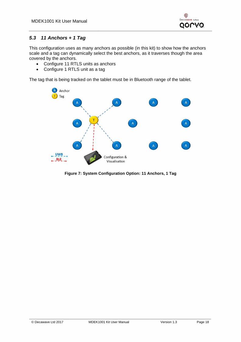
5.3 11 Anchors + 1 Tag
This configuration uses as many anchors as possible (in this kit) to show how the anchors scale and a tag can dynamically select the best anchors, as it traverses though the area covered by the anchors.
• Configure 11 RTLS units as anchors
• Configure 1 RTLS unit as a tag The tag that is being tracked on the tablet must be in Bluetooth range of the tablet.
Figure 7: System Configuration Option: 11 Anchors, 1 Tag

MDEK1001 Kit User Manual
© Decawave Ltd 2017 MDEK1001 Kit User Manual Version 1.3 Page 19
5.4 4 Anchors + 7 Tags + 1 Listener
By configuring one of the devices as a listener device, the data can be captured to a PC directly.
• Set one of the RTLS units (anchor) into PASSIVE mode. In this mode the UWB is enabled but it is not participating in the network
• Connect a PC to this RTLS unit via a USB cable
• On the PC open a shell terminal
• To report the position of all tags that the listener can hear o Type the command “les” (location-engine-show: ASCII format)
▪ or type: “lec” (location-engine-show: csv format) – o Save data from terminal to log file
• In this mode, only position is printed (not individual ranges) The tag that is being tracked on the tablet must be in Bluetooth range of the tablet.
Figure 8: System Configuration Option: 4 Anchors, 7 Tags, 1 Listener

MDEK1001 Kit User Manual
© Decawave Ltd 2017 MDEK1001 Kit User Manual Version 1.3 Page 20
5.5 8 Anchors + 2 Tags + 2 gateways
In order to deploy a network with a gateway, a Raspberry Pi 3 model B is required. Adding a gateway to a PANS network enables the following features:
• Network visualization and monitoring though a web-application
• Access to location and configuration data through an MQTT broker
• Downlink/Uplink IoT data from/to gateway to/from network nodes
Figure 9: Deployment of gateway with MDEK1001: 8 anchors, 2 tags, 2 gateways
For detailed information regarding the deployment of gateway within a PANS network, refer to the DWM1001_Gateway_Quick_Deployment_Guide [8].

MDEK1001 Kit User Manual
© Decawave Ltd 2017 MDEK1001 Kit User Manual Version 1.3 Page 21
6 DRTLS MANAGER USAGE GUIDE
Follow the steps below to get the DWM1001 Two-Way-Ranging Real Time Location System (DRTLS) up-and-running.
6.1 Open the Android Application
• Open the Decawave DRTLS Manager
• If no networks have been previously saved the application will open on the home screen
• If a network was previously saved the application will open on the last viewed network screen
• The home screen will show: o “Decawave DRTLS Manager” o Application version o Button to “Start Device Discovery” o Button to go to the “Instructions” page
Figure 10: Decawave DRTLS Manager Home Screen

MDEK1001 Kit User Manual
© Decawave Ltd 2017 MDEK1001 Kit User Manual Version 1.3 Page 22
6.2 Start Device Discovery
• Tap “Start Device Discovery”
• The application will automatically discover all devices that are in range and powered on
Figure 11: Device Discovery Screen
• Devices will be grouped into o ‘ ETWORKS’ o ‘U ASSIG ED DEVICES’ o ‘U ASSIG ED ETWORKS’
• The following information is shown under each device: o Device Type (Anchor or Tag) o Device Name in the form DW1234 o Network o Bluetooth address o Device ID
• The user can select a specific device by tapping an individual device o The user will get the option to create a New Network name
• Alternatively, to select multiple devices: o Tap-and-hold a single device
o The checkmark symbol will be shown on the left of that device o Other devices can be tapped and added to the selection o Once selected, the button “ASSIGN” in the upper right-hand corner can be
tapped to add these devices to a new (or existing) network

MDEK1001 Kit User Manual
© Decawave Ltd 2017 MDEK1001 Kit User Manual Version 1.3 Page 23
Figure 12: Device Discovery Screen – Select Multiple Devices

MDEK1001 Kit User Manual
© Decawave Ltd 2017 MDEK1001 Kit User Manual Version 1.3 Page 24
6.3 Create a Network
• Name the Network e.g. “Network 1” and
• Tap ‘Save’
Figure 13: Name Network Screen
• The new network will appear in the ‘ ETWORKS’ group and the devices will move from the ‘U ASSIG ED DEVICES’ into that network

MDEK1001 Kit User Manual
© Decawave Ltd 2017 MDEK1001 Kit User Manual Version 1.3 Page 25
Figure 14: Networks& Devices List
6.4 Network Device Configuration
6.4.1 ‘Networks & Devices page’
• Tap a network to see the list of devices in that network
Figure 15: Network Details Screen
Each device in the list shows information about that device.
Figure 16: Network Details Screen: Device Information
• Device Type: A symbol to the left indicates the device type: o Filled circle: Tag. Each tag uses a different color
o Empty triangle: Anchor
o Filled triangle: Initiator Anchor
• Anchor icons:
o Location icon - jumps to the grid screen and zooms to this anchor

MDEK1001 Kit User Manual
© Decawave Ltd 2017 MDEK1001 Kit User Manual Version 1.3 Page 26
o Bluetooth Signal strength icon
o Edit icon – goes to the ‘Details’ screen for that device
• Tag icons:
o Location icon - jumps to the grid screen and zooms to this tag o Ranging Display icons:
▪ Do not show the device on the grid
▪ Show on grid
▪ Show on grid with ranging lines
o Bluetooth Signal strength icon
o Edit icon – goes to the ‘Details’ screen for that device
• Warning icon:
o If the warning icon appears beside a device it can indicate an issue. It will show up if the module has UWB off or UWB passive or when there are two anchors with the same position.
• Tap a device to see a list of parameters of this device
Figure 17: Network Details Screen: Expanded Device Parameters
6.4.2 Remove a Device from a Network
• To remove a device from a network, swipe the device left-to-right.
• The device will disappear from the list and re-appear in the unassigned devices list on the ‘ etworks & Devices’ screen

MDEK1001 Kit User Manual
© Decawave Ltd 2017 MDEK1001 Kit User Manual Version 1.3 Page 27
6.4.3 Device ‘Details’ page
The user can edit the parameters of this device. Note after changing a parameter, the new
setting needs to be saved by tapping in the upper-right of the screen.
Figure 18: Device Details Screen – Anchor & Tag
The following parameters are displayed:
• Device Name
• ID Device ID
• BLE Device Bluetooth address
• NODE TYPE: Set ode to be either “Anchor” or “Tag”. All devices will have a factory-default of ‘tag’ mode. Once the configuration is changed, and saved, the device will remember the new setting.
• NETWORK: Add the Node to a network (either a previously created network or, if none exists, the option to create a new network will appear)
• UWB: ‘off’, ‘passive’ or ‘active’. o Set to ‘active’ to range in the network. o Set to ‘passive’ if used as a listener.
• If in tag mode: o NORMAL UPDATE RATE: Set the location update rate. The default is 10 Hz
(calculates a location 10 times per second) but can be changed to other rates o STATIONARY UPDATE RATE: Set the location update rate to be used when
the device is stationary (detected by the motion sensor)
• UWB FIRMWARE UPDATE: Allows firmware update to propagate to this device
• LED: Disables/enables the LEDs on the board. May be used by a user to help identify which device is referenced.
• If in anchor mode:

MDEK1001 Kit User Manual
© Decawave Ltd 2017 MDEK1001 Kit User Manual Version 1.3 Page 28
o INITIATOR Configure this anchor as an initiator. At least one of the anchors must be an initiator in the network. The initiator will start and control the network
o POSITION Position: The x,y,z co-ordinate of the anchor in the grid. Will be automatically populated if this device participated in auto-positioning.
▪ X position ▪ Y position ▪ Z position
• If in tag mode: o STATIONARY DETECTION: Enables/disables motion sensor operation. If
disabled, then the stationary update rate will not be available. o RESPONSIVE MODE: o LOCATION ENGINE:
6.4.4 Tip: Label your Devices
• It is often useful to label your devices so they can be easily identified on the Android application
• To do this uncheck the LED parameter and tap ‘SAVE’. This will disable the LEDs on that device, and enable the user to locate it in the room
• The user can place a label on the enclosure of that device with an identifier such that it can be quickly found in the application e.g. the device ID
• When completed, the user can check the LED parameter and tap ‘SAVE’ to enable the LEDs again.

MDEK1001 Kit User Manual
© Decawave Ltd 2017 MDEK1001 Kit User Manual Version 1.3 Page 29
6.4.5 Position the Anchors
6.4.5.1 By using the Auto-Positioning Feature (for up to 4 anchors)
Note 1: The Auto-Positioning function is a quick setup feature to automatically determine the anchor locations. Note that this feature may result in a small error in anchor location, making reported tag locations less accurate. For best results it is recommended that anchor positions are measured to cm accuracy and manually entered (see below) Note 2: Ensure Line-of-Sight between the anchors during these steps
Figure 19: Auto-Positioning Screen
• START On the ‘ etwork Details’ screen, tap the “Auto-Position” button in the upper right pull-down menu (anchors within Bluetooth range appear)
• RE-ORDER Re-order the anchors in the list to match their locations in the room: o Order the anchors anti-clockwise in the room (as shown above) o The 1st anchor in the list is the (0,0) co-ordinate
• MEASURE Tap “Measure” to start the auto-positioning
• PREVIEW Tap ‘PREVIEW’ to check locations before saving
• SET HEIGHTS Enter heights of the anchors by tapping ‘Z-AXIS’
• SAVE Save the anchors setup by tapping ‘SAVE’
• The location of the other anchors are calculated from the initial 3 anchor locations
• Errors will propagate through the anchors so the usage is confined to small-scale systems e.g. up to 4 anchors
• Auto-positioning can only be used on the anchors that are within Bluetooth range of the android device.

MDEK1001 Kit User Manual
© Decawave Ltd 2017 MDEK1001 Kit User Manual Version 1.3 Page 30
Figure 20: Auto-Positioning: Anchor Positioning Rules
6.4.5.2 By Manual Positioning
• In turn, open each anchor’s device configuration screen
• Enter the x, y, z co-ordinates of the anchors
6.5 Show Location
• Ranging starts automatically once devices have been added to the network and the
display option has been tapped (it defaults to off)
• From the Network Details screen, tap the “Grid” option at the top of the screen to see the grid
• Pinch to zoom in or out
• Tags automatically select the optimum 4 anchors for ranging
• A floorplan can be uploaded into the application from the device’s gallery

MDEK1001 Kit User Manual
© Decawave Ltd 2017 MDEK1001 Kit User Manual Version 1.3 Page 31
Figure 21: Grid Screen – Anchor Placement & Tag Tracking
In networks where there are more than 4 anchors, the anchor selection can be viewed on the grid by moving the tag from one position to another.
Figure 22: Grid Screen – Anchor Selection
MDEK1001 Kit User Manual
© Decawave Ltd 2017 MDEK1001 Kit User Manual Version 1.3 Page 32
In the upper-right pulldown menu – there are 2 options:
• Floor plan
• Show grid

MDEK1001 Kit User Manual
© Decawave Ltd 2017 MDEK1001 Kit User Manual Version 1.3 Page 33
6.6 Side Menu Options
Tap the menu icon on the top left of the home screen. This will display the following options:
o A list of previously saved networks o “Networks & Devices” o “Position log” o “Development tools”
o Only visible if enabled in the Settings menu o “Settings”
Figure 23: Decawave DRTLS Manager Side Menu Screen
6.6.1 Position Log
Shows ranges and locations for all devices

MDEK1001 Kit User Manual
© Decawave Ltd 2017 MDEK1001 Kit User Manual Version 1.3 Page 34
Figure 24: Decawave DRTLS Manager Position Log
6.6.2 Settings
The following settings are available
• Units “Imperial” yards or “Metric” metres
• Version Application version
• About General information

MDEK1001 Kit User Manual
© Decawave Ltd 2017 MDEK1001 Kit User Manual Version 1.3 Page 35
Figure 25: Decawave DRTLS Manager Settings Screen

MDEK1001 Kit User Manual
© Decawave Ltd 2017 MDEK1001 Kit User Manual Version 1.3 Page 36
7 LOGGING DATA VIA THE USB PORT
Tag location data can be logged using a USB connection instead of using the Android application. Note also that the PC terminal can be used to configure the anchors and tags – the Android application is not necessarily needed.
7.1 Instructions
1. Setup the anchors and tags network via the Android application (see section 6) 2. Download and install the J-Link software pack from Segger
▪ https://www.segger.com/downloads/jlink/#J-LinkSoftwareAndDocumentationPack
3. Download and install a common PC terminal program e.g. Tera Term ▪ http://download.cnet.com/Tera-Term/3000-2094_4-75766675.html
4. Connect the tag to the PC via USB cable 5. Open the device manager to identify what com port is assigned to the Tag, in this
case COM20
6. Once the com port has been identified open up Tera Term. Select the appropriate COM port as shown, and set the terminal baud rate to 115200. The tag should now be connected.

MDEK1001 Kit User Manual
© Decawave Ltd 2017 MDEK1001 Kit User Manual Version 1.3 Page 37
7. Next press the PC Enter key two times and the prompt below appears:
8. Enter the command ‘nmt’ and press the return key twice which sets the tag into Active mode
9. Enter ‘les’ to display the location estimates of the tag
7.2 Example Output
In the example above, ‘08AF’ is an Anchor ID:
• ‘[0.5,0.5,1.97]’ is the Anchor coordinate for Anchor ‘08AF’ in the form of [x,y,z].
• ‘1.14’ is the estimated range between the Tag and Anchor ‘08AF’
• ‘est[1.05,1.04,1.15,9 ] ‘ is the estimated location of the Tag. In the form of [x,y,z,quality factor]. (The quality factor is a measure of confidence of the accuracy of the location estimate based on the ranges received)
7.3 Other Commands
Once tag is connected to tera term press ‘ ?’ or ‘help’ and then the return key to obtain a list of the executable commands. These commands are listed below. dwm> help Usage: <command> [arg0] [arg1] ... Build-in commands:

MDEK1001 Kit User Manual
© Decawave Ltd 2017 MDEK1001 Kit User Manual Version 1.3 Page 38
** Command group: Base ** ?: this help help: this help quit: quit ** Command group: GPIO ** gc: GPIO clear gg: GPIO get gs: GPIO set gt: GPIO toggle ** Command group: SYS ** f: Show free memory on the heap reset: Reboot the system si: System info ut: Show device uptime frst: Factory reset ** Command group: SENS ** twi: General purpose TWI read aid: Read ACC device ID av: Read ACC values scs: Stationary config set scg: Stationary config get ** Command group: LE ** les: Show meas. and pos. lec: Show meas. and pos. in CSV lep: Show pos. in CSV ** Command group: UWB ** utpg: Get TxPwr utps: Set TxPwr ** Command group: UWBMAC ** nmg: Get node mode nmp: Set UWB mode to passive nmo: Set UWB mode to off nma: Set mode to AN nmi: Set mode to ANI nmt: Set mode to TN nmtl: Set mode to TN-LP nmb: Set mode to BN la: Show AN list lb: Show BN list nis: Set Network ID nls: Set node label udi: Show incoming IoT data uui: Send IoT data stg: Get stats stc: Clear stats

MDEK1001 Kit User Manual
© Decawave Ltd 2017 MDEK1001 Kit User Manual Version 1.3 Page 39
** Command group: API ** tlv: Send TLV frame aurs: Set upd rate aurg: Get upd rate apg: Get pos aps: Set pos acas: Set anchor config acts: Set tag config aks: Set encryption key akc: Clear encryption key ans: Set NVM usr data anc: Clear NVM usr data ang: Get NVM usr data ** Tips ** Press Enter to repeat the last command
MDEK1001 Kit User Manual
© Decawave Ltd 2017 MDEK1001 Kit User Manual Version 1.3 Page 40
8 REFERENCES
8.1 Listing
Reference is made to the following documents in the course of this document:
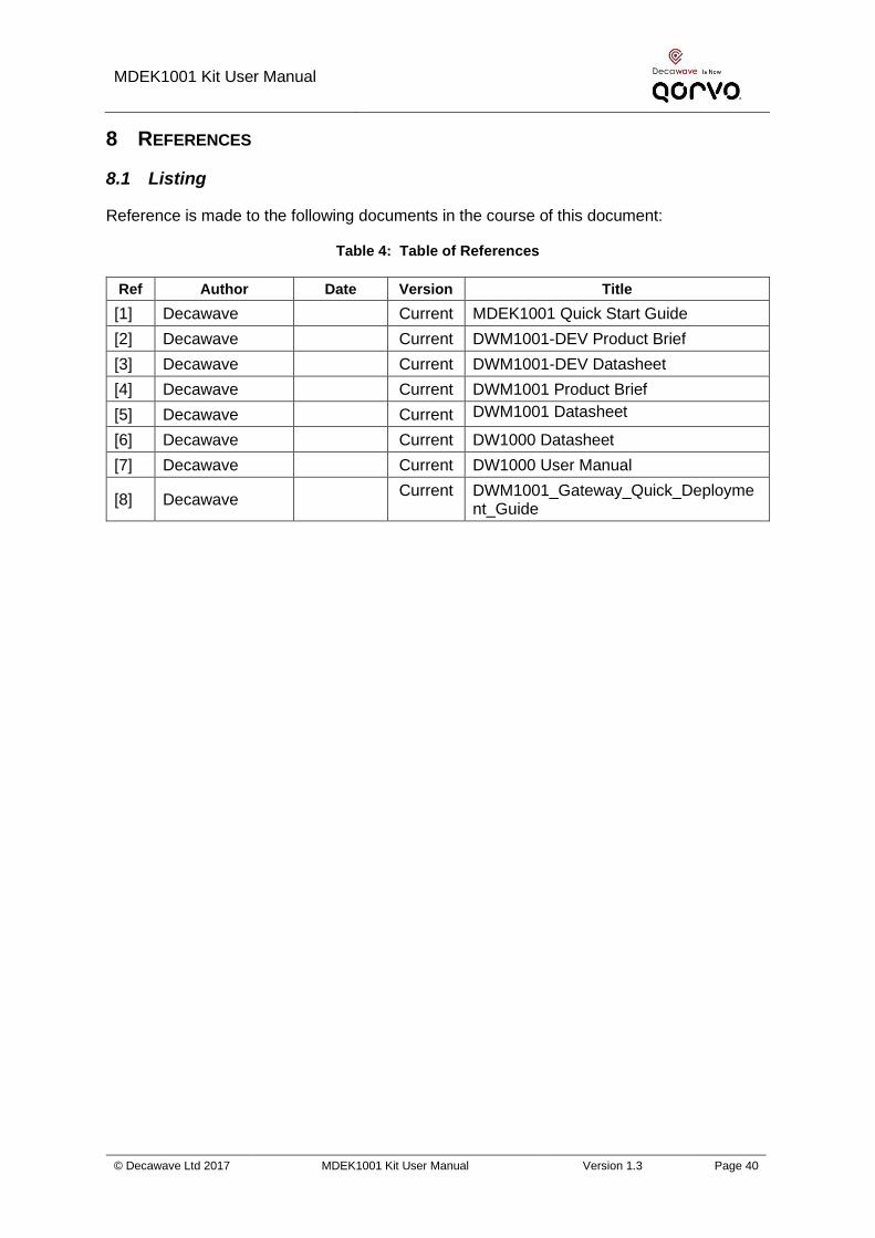
Table 4: Table of References
Ref Author Date Version Title
[1] Decawave Current MDEK1001 Quick Start Guide
[2] Decawave Current DWM1001-DEV Product Brief
[3] Decawave Current DWM1001-DEV Datasheet
[4] Decawave Current DWM1001 Product Brief
[5] Decawave Current DWM1001 Datasheet
[6] Decawave Current DW1000 Datasheet
[7] Decawave Current DW1000 User Manual
[8] Decawave Current DWM1001_Gateway_Quick_Deployme
nt_Guide
MDEK1001 Kit User Manual
© Decawave Ltd 2017 MDEK1001 Kit User Manual Version 1.3 Page 41
9 DOCUMENT HISTORY
9.1 Revision History
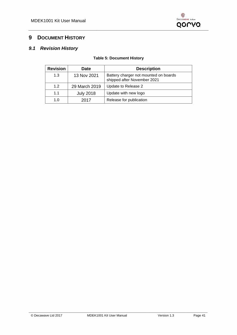
Table 5: Document History
Revision Date Description
1.3 13 Nov 2021 Battery charger not mounted on boards shipped after November 2021
1.2 29 March 2019 Update to Release 2
1.1 July 2018 Update with new logo
1.0 2017 Release for publication

MDEK1001 Kit User Manual
© Decawave Ltd 2017 MDEK1001 Kit User Manual Version 1.3 Page 42
10 FURTHER INFORMATION
Decawave develops semiconductors solutions, software, modules, reference designs - that enable real-time, ultra-accurate, ultra-reliable local area micro-location services. Decawave’s technology enables an entirely new class of easy to implement, highly secure, intelligent location functionality and services for IoT and smart consumer products and applications. For further information on this or any other Decawave product, please refer to our website www.decawave.com.