MD12-1 Type to-100 Bottom Blocks
10
Rev. Date 1/23/00 BULLETIN MD-12-1 1 BULLETIN MD-12-1 Type TO-100 Bottom Blocks & Upper Blocks GENERAL This service bulletin provides the necessary information to inspect, lubricate, repair, and store the Type TO-100 Bottom Blocks and Upper Blocks. Replacement parts information for these block assemblies is provided in a separate parts manual specifically tailored to the applicable machine. Inspection and lubrication are covered under the maintenance topic followed by the repair instructions covered under the repair topic. The information, specifications and illustrations in this publication are based on the information for TO-100 bottom blocks and TO-100 upper blocks at the time that this manual was printed. Continuing improvements and advancement of product design may cause changes to these components which may not be included in this manual. Each publication is periodically reviewed and revised to update and include these changes in later editions. Any questions regarding the information in this document should be directed to Morris Material Handling. MAINTENANCE General The following topics outline the lubrication requirements, inspection procedures, and reeving instructions for the Type TO-100 Bottom Blocks and Upper Blocks. Lubrication NOTICE Failure to lubricate the block assemblies before use will lead to premature wear and possible bearing failure. New bottom blocks and new upper blocks may not be adequately lubricated prior to leaving the factory and must be lubricated prior to use. NOTICE At the time of the printing of the Bulletin, the manufacturers listed in the lubrication specification complied with the requirements of P&H 472. Manufacturers can change lubrication formulation from time to time without advising Morris Material Handling. To prevent any possible conflict obtain current copy of P&H lubrication specification and work with your lubrication supplier to find a product which satisfies the specification. NOTICE There are various types of greases, some of which are not compatible with each other. Thickeners such as clay base, polyurea, or calcium may result in incompatibilities. Always consult your lubricant supplier before changing types or brands of greases to prevent possible problems. GENERAL. There are three separate points which must be lubricated on each bottom block and one lube point on the upper block. They are: the hook latch pivot, the hook thrust bearing, and the sheave bearings. The sheave bearings must be lubricated on the upper block. HOOK LATCH. Lubricate the hook latch pivot point using SAE-30 motor oil at least once a week. Use an oil can to apply oil directly to the hook latch pivot point. SHEAVE BEARINGS. Lubricate the sheave bearings at least once every three months, through the lube fittings provided in the end of the sheave pin, using multipurpose grease conforming to P&H specification No. 472. Pump grease into the sheave pin lube fittings until it can be seen coming out between the sheave and side plates. Figure 1, Multipurpose Grease (MPG), lists a few of the greases which satisfy this lubrication requirement.
-
Upload
jesuscalvillo -
Category
Documents
-
view
7 -
download
1
Transcript of MD12-1 Type to-100 Bottom Blocks

Rev. Date 1/23/00 BULLETIN MD-12-1 1
BULLETIN MD-12-1
Type TO-100 Bottom Blocks & Upper Blocks
GENERAL
This service bulletin provides the necessary informationto inspect, lubricate, repair, and store the Type TO-100Bottom Blocks and Upper Blocks. Replacement partsinformation for these block assemblies is provided in aseparate parts manual specifically tailored to theapplicable machine. Inspection and lubrication arecovered under the maintenance topic followed by therepair instructions covered under the repair topic.
The information, specifications and illustrations in thispublication are based on the information for TO-100bottom blocks and TO-100 upper blocks at the time thatthis manual was printed. Continuing improvements andadvancement of product design may cause changes tothese components which may not be included in thismanual. Each publication is periodically reviewed andrevised to update and include these changes in latereditions. Any questions regarding the information in thisdocument should be directed to Morris MaterialHandling.
MAINTENANCE
General
The fo l low ing top ics ou t l i ne the lub r i ca t ionrequirements, inspection procedures, and reevinginstructions for the Type TO-100 Bottom Blocks andUpper Blocks.
Lubrication
NOTICE
Failure to lubricate the block assemblies beforeuse will lead to premature wear and possiblebearing failure. New bottom blocks and newupper blocks may not be adequately lubricatedprior to leaving the factory and must belubricated prior to use.
NOTICE
At the time of the printing of the Bulletin, themanufacturers l is ted in the lubr icat ionspecification complied with the requirements ofP&H 472 . Manufac tu re rs can changelubrication formulation from time to time withoutadvising Morris Material Handling. To preventany possible conflict obtain current copy of P&Hlubrication specification and work with yourlubrication supplier to find a product whichsatisfies the specification.
NOTICE
There are various types of greases, some ofwhich are not compatible with each other.Thickeners such as clay base, polyurea, orcalcium may result in incompatibilities. Alwaysconsult your lubricant supplier before changingtypes or brands of greases to prevent possibleproblems.
GENERAL. There are three separate points which mustbe lubricated on each bottom block and one lube pointon the upper block. They are: the hook latch pivot, thehook thrust bearing, and the sheave bearings. Thesheave bearings must be lubricated on the upper block.
HOOK LATCH. Lubricate the hook latch pivot pointusing SAE-30 motor oil at least once a week. Use an oilcan to apply oil directly to the hook latch pivot point.
SHEAVE BEARINGS. Lubricate the sheave bearings atleast once every three months, through the lube fittingsprovided in the end of the sheave pin, us ingmultipurpose grease conforming to P&H specificationNo. 472. Pump grease into the sheave pin lube fittingsuntil it can be seen coming out between the sheave andside plates. Figure 1, Multipurpose Grease (MPG), listsa few of the greases which satisfy this lubricationrequirement.

Revised 1/23/00
2 Type TO-100 Bottom Blocks & Upper Blocks
P&HSPEC. NO.
AMBIENT RANGE
MILITARY SPEC. NO.
EQUIVALENTLUBRICANTS
MANUFACTURERS
472A(NLGI #0 EP)
*Below - 10˚F(-12˚C)
Not Available Conolith EP #0 Continental Oil Company
Lidok EP #9 Exxon Company
Amolith Grease] No. 0 EP Amoco Oil Company
Mobilux EP #0 Mobil Oil Company
Alvania EPRO Shell Oil Company
Prestige 740 EP Sun Company
Multifak EP #0 Texaco, Incorporated
Unoba EP NLGI #0 Union Oil Company of Calif.
Dura-Lith Grease EP #0 Chevron U.S.A., Inc.
Kendall L-406 Kendall Refining Co.
472B(NLGI #1 EP)
*-20 to +40˚F(-29 to 4˚C)
Not Available Litholine H EP 1 Arco Petroleum Products Co.
Conolith EP #1 Continental Oil Company
Rolubricant 1or Lidok EP #1 Exxon Company (A)
Mobilux EP #1 Mobil Oil Corporation
Alvania EP #1 Shell Oil Company
Prestige 741 EP Sun Company
Multifak EP #1 Texaco, Incorporated
Amolith Grease #1 EP Amoco Oil Company
Unoba EP NLGI #1 Union Oil Company of Calif.
Dura-Lith Grease EP #1 Chevron U.S.A., Inc.
Gulf Crown Grease EP-1 Gulf Oil Company
Kendall L-416 Kendall Refining Co.
Philube EP-1 Phillips Petroleum Co.
472(NLGI #2 EP)
*+20 to 125˚F(-6 to 52˚C)
Not Available Litholine H EP 2 Arco Petroleum Products Co.
Conolith EP #2 Continental Oil Company
Rolubricant 2 or Lidok #2 Exxon Company (A)
Mobilux EP #2 Mobil Oil Company
Alvania EP #2 Shell Oil Company
Prestige 742 EP Sun Company
Multifax EP #2 Texaco, Incorporated
Amolith Grease #2 EP Amoco Oil Company
Unoba EP NLGI #2 Union Oil Company of Calif.
Dura-Lith Grease EP #2 Chevron Oil Company
Gulf Crown Grease EP-2 Gulf Oil Company
Kendall L-426 Kendall Refining Co.
Philube EP-2 Phillips Petroleum Co.
*Pumpability tests also required when used in centralized lubrication systems. Consult manufacturer of system.(A) Rolubricant for steel mill applications.
IIssue No. 9, 8-82P115A
Figure 1. Multipurpose Grease (MPG)

Morris Material Handling
BULLETIN MD-12-1 3
HOOK THUST BEARING. Repack the hook thrustbear ing at least once every six months usingmultipurpose grease conforming to P&H specificationNo. 472. Figure 1, Multipurpose Grease (MPG), lists afew of the greases which satisfy this lubricationrequirement.
Inspection
GENERAL. Use the following procedures to inspect the components of the bottom block and upper block. Addi-tional specific inspection procedures are outlined as part of the cleaning and inspection topic found under the maintenance topic.
Regular, periodic inspection is essential to continuedsafe operation of the bottom block and upper block.Careful inspection on a regular basis will revealpotentiality hazardous conditions while still in the earlystages, allowing corrective action to be taken before thecondition becomes hazardous.
Any deficiency revealed through periodic inspectionshal l be repor ted to an appointed person. Adetermination must be made as to whether a deficiencyconstitutes a safety hazard before resuming use of thebottom block or upper block.
HOOKS. During the inspection of the bottom block, in-spect the hook and replace it if any of the following con-ditions exist:
! DANGERWARNING
An excessively bent, twisted, worn, orsprung hook can fail to support the load,causing the load to fall. This can result inserious personal injury or death. Withoutexception, an excessively bent, twisted,worn or sprung hook must be replaced. Anexcessive throat opening, severely bentand/or sprung hook, indicates that the hookhas been abused or overloaded. In this caseall load bearing components of the entirehoist unit must be checked on a daily basisuntil there is assurance that no damage hasoccurred to these components.
1. Deformation.
2. Chemical damage (if the hook is exposed tocorrosive chemicals or atmosphere).
3. A throat opening in excess of 15% of normal.
4. A twist of more than 10% from the plane of anunbent hook.
5. Wear in excess of 10% of the original dimension atthe load carrying point.
6. Proper fit of the hook latch. If the latch snaps pastthe tip of the hook, the hook is sprung, and must bereplaced.
7. Check the hook to verify that it is properly securedin the bottom block. Also check the hook latch fordamage or restricted movement.
8. Inspect the hook for cracks.
SHEAVES. During the inspection of the bottom block orupper block, inspect the sheaves for the followingconditions:
1. Check the sheave grooves using a sheave gauge.Check that the sheave has not worn beyond thelimits allowed by the sheave gauge.
2. Make sure that the sheave is properly sized to thewire rope. Never use a larger sheave with a smallerwire rope, and vise verse.
3. Replace sheaves which the wire rope has worn intothe surface of the sheave. This condition greatlyaccelerates the wear of the wire rope.
Reeving
No specific reeving instructions are provided in thispublication due to the variety of bottom blocks andupper blocks which are covered. Reeving diagramswhich apply to th is bot tom block/upper blockcombination are provided in the applicable replacementparts manual for this machine.
Use the following instructions as a guideline whenreeving this bottom block:
1. Refer to the correct reeving diagram for this bottomblock as shown in the replacement parts manual forthis machine.
2. Refer to the appropriate repair procedure anddisassemble the bottom block and upper block, orremove the sheave guards depending on the type ofblock, allowing access to the individual sheaves.
3. Remove the sheave pin and remove the sheaves.
4. Start at one end of the bottom block, loop the wirerope around each sheave. As the rope is passedaround the sheave, install the sheave and secure itin the block using the sheave pin. Do not slide thesheave pin the all the way through the sheaveframe, but instead push it in just enough to holdeach sheave in place. Repeat this procedure foreach remaining sheave.
Revised 1/23/00
4 Type TO-100 Bottom Blocks & Upper Blocks
5. After the wire rope has been passed around all ofthe sheaves and the sheaves have been installedinto the bottom block and upper block, secure thesheave pin using the keeper plate and screws.
6. Check the reeving to ensure that it is correct inrelation to the applicable reeving diagram.
NOTICE
Correct reeving diagrams are located in theapplicable replacement parts manuals for thismachine.
7. Lubricate the sheaves as described under the topic,Lubrication, Sheave Bearings.
BOTTOM BLOCK REPAIR
General
The following procedure describes the disassembly,cleaning, inspection and repair, and assembly of theType TO-100 bottom block. The following procedure iswritten on the basis that the bottom block is beingcompletely disassembled, cleaned, and assembled. Ifonly partial disassembly is required, perform only thedisassembly steps required to accomplish the neededrepairs.
Disassembly
Use the following procedure to disassemble the bottomblock (see Figure 2, Type TO-100 Bottom Block)
1. Lower the bottom block onto saw horses orblocking.
2. Unreeve the wire rope as necessary to permit theneeded repair.
! DANGERWARNING
Inadvertent operation of the crane duringservice or maintenance can result in injuryor death of personnel. Shut down theoperation of the crane, open, lockout andtag the operator’s controls and the powerdisconnect switch prior to working on thebottom block or upper block.
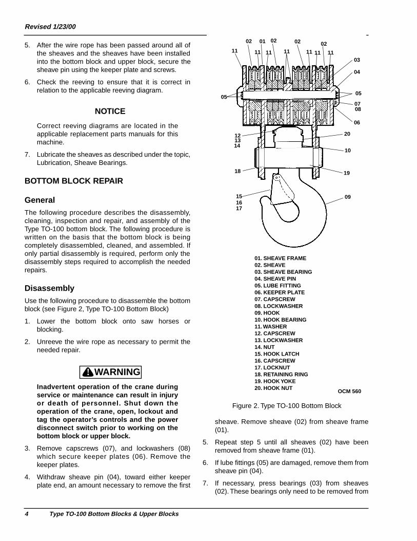
3. Remove capscrews (07), and lockwashers (08)which secure keeper plates (06). Remove thekeeper plates.
4. Withdraw sheave pin (04), toward either keeperplate end, an amount necessary to remove the first
sheave. Remove sheave (02) from sheave frame(01).
5. Repeat step 5 until all sheaves (02) have beenremoved from sheave frame (01).
6. If lube fittings (05) are damaged, remove them fromsheave pin (04).
7. If necessary, press bearings (03) from sheaves(02). These bearings only need to be removed from
0102 02 02 02
03
04
05
06
0708
09
10
11 11 11 11 11 11 11
121314
151617
18 19
20
05
01. SHEAVE FRAME02. SHEAVE03. SHEAVE BEARING04. SHEAVE PIN05. LUBE FITTING06. KEEPER PLATE07. CAPSCREW08. LOCKWASHER09. HOOK10. HOOK BEARING11. WASHER12. CAPSCREW13. LOCKWASHER14. NUT15. HOOK LATCH16. CAPSCREW17. LOCKNUT18. RETAINING RING19. HOOK YOKE20. HOOK NUT OCM 560
Figure 2. Type TO-100 Bottom Block

Morris Material Handling
BULLETIN MD-12-1 5
the sheaves if they are to be replaced. Refer to theinspection procedure to determine if bearingsshould be replaced.
8. Support hook (09) using blocking.
9. Remove lock nut (14), lockwasher (13), andcapscrew (12) which secure hook nut (20).
10. Remove hook nut (20) from hook (09).
11. Lower hook (09) from sheave frame (01) leavingbearing (10) in its bearing recess.
12. Remove bearing (10) from sheave frame (01).
13. If hook latch (15) is damaged, remove capscrew(16) and lock nut (17) which secure it to hook (09),and remove the hook latch.
Cleaning and Inspection
GENERAL. Regular, periodic inspection is essential to the continued safe operation of the bottom block. Care-ful inspection on a regular basis will reveal potentially hazardous conditions while still in the early stages, al-lowing corrective action to be taken before the condition becomes hazardous.
Any deficiency revealed through periodic inspectionmust be repor ted to an appointed person. Adetermination must be made as to whether a deficiencyconstitutes a safety hazard before resuming use of thebottom block.
CLEANING. Clean all of the bottom block parts using solvent.
! DANGERWARNING
Use appropriate eye protection whenworking with compressed air to prevent eyeinjury.
Dry each part using low pressure compressed air (15psimaximum). Never use hot alkaline solutions on bearingsor other finished parts as the alkali will damage thefinished surfaces.
INSPECTION. Use the following procedure to inspect the components of the bottom block.
1. Inspect all bearings for wear, binding, play, distortedraces, roller wear or damage. If necessary, repackall bearings with clean lubricant before installingthem into the sheaves.
2. Smooth out ridges which may be evident on thesheave pin. Be particularly careful of those areas onwhich the bearings ride.
3. Inspect all threaded items, and replace those itemswhich have damaged threads.
4. Inspect the hook as described under the topic,Inspection, Hooks.
5. Inspect the sheaves as described under the topic,Inspection, Sheaves.
6. Inspect all remaining parts for evidence of wear ordamage. Replace or repair any part which is inquestionable condition. The cost of the part is oftenminor in comparison with the cost of redoing the jobshould the part fail.
Assembly
Use the following procedure to assemble the bottomblock (see Figure 2, Type TO-100 Bottom Block).
1. If necessary, assemble a new hook latch (15) tohook (09) using capscrew (16) and lock nut (17).Securely tighten the capscrews and nuts.
2. If bearings (03) had been removed from sheaves(02), press the bearings into the sheaves.
3. Support sheave frame (01) on blocking such thatthe sheave opening is facing up.
4. Position bearing (10) into the sheave frame bearingrecess.
5. Raise hook (09) into sheave frame (01) from thebottom. Make sure that bearing (10) remainsseated squarely in the bearing recess.
6. Thread hook nut (20) onto hook (09). Tighten thehook nut until the play between the thrust bearingand the hook nut has been removed.
7. Either tighten or loosen the hook nut as necessaryto align the holes in the hook nut with the drilled holein the hook.
8. Install capscrew (12), lockwasher (13), and lock nut(14) securing hook nut (20) to hook (09).
9. Insert sheave pin (04) into either keeper plate sideof sheave frame (01). Do not push it past the innerface of the sheave frame side plate.
10. Install a sheave (02) into the sheave frame, andalign the bearing bore with sheave pin (04).
11. Slide sheave pin (04) through the sheave andbearing an amount sufficient to secure the sheave.

Revised 1/23/00
6 Type TO-100 Bottom Blocks & Upper Blocks
12. Repeat the preceding steps until all sheaves (02)have been installed.
13. Push sheave pin (04) into the sheave frame until thekeeper plate slots are aligned with the faces of thesheave frame.
14. Install keeper plates (06).
15. Secure the keeper plates using capscrews (07),and lockwashers (08). Securely t ighten thecapscrews.
16. If lube fitting (05) is damaged, remove it fromsheave pin (04), and replace it with a new fitting.
17. Lubricate the bottom block sheaves as describedunder the topic, Lubrication, Sheave Bearings.
18. Reeve the bottom block as described under thetopic, Reeving.
19. Test for proper operation before placing back intoservice.
UPPER BLOCK REPAIR
General
The following procedures describe the disassembly,cleaning, inspection and repair, and assembly of theTO-100 upper block. The following procedure is writtenon the basis that the upper block is being completelydisassembled, cleaned, and assembled.
Disassembly
Use the following procedure to disassemble the upperblock (see Figure 3, Type TO-100 Upper Block).
1. Lower the bottom block onto saw horses orblocking.
2. Unreeve the wire rope as necessary to permit theneeded repair.
! DANGERWARNING
Working on or near an overhead crane whilein operation is hazardous, and can result inthe injury or death of personnel. Shut downthe operation of the crane, open, lockoutand tag the operator’s controls and thepower disconnect switch prior to workingon the bottom block or upper block.
3. Remove capscrews (04), and lockwashers (05)which secure keeper plate (03). Remove the keeperplate.
4. Withdraw sheave pin (07), toward the keeper plateend, an amount necessary to remove the firstsheave. Remove sheave (01) from sheave frame(08).
5. Repeat step 5 until all sheaves (01) have beenremoved from sheave frame (08).
01
02
03
0405
0606
07
08
01. SHEAVE02. SHEAVE BEARING03. KEEPER PLATE04. CAPSCREW05. LOCKWASHER06. LUBE FITTING07. SHEAVE PIN08. SHEAVE FRAME
OCM 561
Figure 3. Type TO-100 Upper Block
Morris Material Handling
BULLETIN MD-12-1 7
6. If lube fittings (06) are damaged, remove them fromsheave pin (07).
7. If necessary, press bearings (02) from sheaves(01). These bearings only need to be removed fromthe sheaves if they are to be replaced. Refer to theinspection procedure to determine if bearingsshould be replaced.
Cleaning, Inspection, and Repair
GENERAL. Regular, periodic inspection is essential to the continued safe operation of an upper block. Careful inspection on a regular basis will reveal potentially haz-ardous conditions while still in the early stages, allowing corrective action to be taken before the condition be-comes hazardous.
Any deficiency revealed through periodic inspectionmust be repor ted to an appointed person. Adetermination must be made as to whether a deficiencyconstitutes a safety hazard before resuming use of theupper block.
CLEANING. Clean the upper block components usingsolvent.
! DANGERWARNING
Use appropriate eye protection whenworking with compressed air to preventpossible eye injury.
Dry each part using low pressure compressed air (15psimaximum).
Never use hot alkaline solutions onbearings or other finished parts as the alkali willdamage the finished surfaces.
INSPECTION. Use the following procedure to inspect the components of the upper block.
1. Inspect all bearings for wear, binding, play, distortedraces, roller wear or damage. If necessary, repackall bearings with clean lubricant before installingthem into the sheaves.
2. Smooth out ridges which may be evident on thesheave and saddle pin. Be particularly careful ofthose areas on which the bearings ride.
3. Inspect all threaded items, and replace those itemswhich have damaged threads.
4. Check the sheave grooves using a sheave gauge.Check that the sheave has not worn beyond thelimits allowed by the sheave gauge.
5. Make sure that the sheave is properly sized to thewire rope. Never use a larger sheave with a smallerwire rope, and vise verse.
6. Replace sheaves which the wire rope has worn intothe surface of the sheave. This condition greatlyaccelerates the wear of the wire rope.
7. Inspect all remaining parts for evidence of wear ordamage. Replace or repair any part which is inquestionable condition. The cost of the part is oftenminor in comparison with the cost of redoing the jobshould the part fail.
Assembly
Use the following procedure to assemble the upperblock (see Figure 3, Type TO-100 Upper Block).
1. If bearings (02) had been removed from sheaves(01), press the bearings into the sheaves.
2. Insert sheave pin (07) into the keeper plate side ofsheave frame (08). Do not push it past the innerface of the sheave frame side plate.
3. Install a sheave (01) into the sheave frame, andalign the bearing bore with sheave pin (07).
4. Slide sheave pin (07) through the sheave andbearing an amount sufficient to secure the sheave.
5. Repeat the preceding steps until all sheaves (01)have been installed.
6. Push sheave pin (07) into the sheave frame until thekeeper plate slot is aligned with the face of thesheave frame.
7. Install keeper plate (03).
8. Secure the keeper plate using capscrews (04), andlockwashers (05). Securely tighten the capscrews.
9. If lube fittings (06) are damaged, remove them fromsheave pin (07), and replace with a new fittings.
10. Lubricate the upper block as described under thetopic, Lubrication.
11. Test for proper operation before placing back intoservice.
WIRE ROPE REPLACEMENT
The following instructions describe the method whichHarnischfeger has developed to replace the hoistcables on an overhead crane. This procedure applies towire rope reeving patterns of four or more parts of line.The procedure requires the use of three sets of steelsaw horses, one reel of new wire rope, one empty reel

Revised 1/23/00
8 Type TO-100 Bottom Blocks & Upper Blocks
on which to take up the old wire rope, one wire ropechanging reel, one wire rope splice, and four persons.
1. Place a jumper across the contacts of the gearedlimit switch, disabling the switch functions.
2. Lower the bottom block onto a set of steel sawhorses, supporting it in a vertical position.
3. Slip the reel of new wire rope over the hub of a wirerope changing reel. The wire rope changing reelshould be of the style which has a removable topflange or ring. Support the wire rope changing reelon a set of saw horses so as to permit free rotation.
! DANGERWARNING
Wire rope will fall to the floor when it isdetached from the hoist drum, and canresult in injury or death. Attach a hand lineto the end of the hoist wire rope beforedetaching the wire rope from the hoist drum.
4. The second person, on the crane, is to detach theleft hand wire rope end from the hoist drum andlower it to the third person on the floor by means ofa hand line. Do not allow the wire rope to freely fallto the floor.
5. The person on the floor is to splice (or weld) the endof the old wire rope to the end of the new wire ropeusing an appropriate splice.
6. The person on the crane is to attach a second handline to the right hand end of the wire rope. Thisperson is then to pass the hand line around thedrum one full revolution and pass it down to thefourth person on the floor.
7. While the fourth person on the floor is keeping thesecond hand line taut, the person on the craneshould remove the clamp from the right hand wirerope end.
8. Keeping the second hand line taut, the craneoperator should operate the hoist drive slowly in theraise direction pulling the new wire rope through allof the sheaves. Continue this operation until theright hand end of the old wire rope reaches the floorplus an amount required to connect the wire ropeend to the take up reel.
NOTICE
Connect the old wire rope to the take up reel sothat it winds up from the bottom side of the reel.Also, make sure that the wire rope is started atthe side of the reel, not in the middle.
9. With the take up reel supported in the same manneras the wire rope changing reel, continue to operatethe hoist drive in the raise direction until all of the oldwire rope has been removed from the drum and thenew wire rope has started (two full wraps) onto thehoist drum.
NOTICE
While the new wire rope is being guided into thebottom block sheaves by the first person, thefourth person should be rotating the take upreel to wind up the old wire rope as it comes offthe hoist drum.
10. Second person: secure the end of the new wirerope to the hoist drum using the cable clamps.
! DANGERWARNING
Wire rope will fall to the floor when it isdetached from the hoist drum, and canresult in injury or death. Attach a hand lineto the end of the hoist wire rope beforedetaching the wire rope from the hoist drum.
11. After the end of the new wire rope has beenproperly secured to the hoist drum, separate thesplice from and lower the end of the old wire rope tothe floor by means of a hand line. Do not allow theend of the wire rope to freely fall to the floor.Continue to wind up the remainder of the old cableand secure it to the take up reel.
12. Disconnect the end of the new wire rope from thechanging reel and secure a hand line to it. The handline should be fed down from the second person onboard the crane.
NOTICE
Fourth person: climb onto the crane to assistthe second person.
13. Pass the hand line around the hoist drum two fullrevolutions. Working together, the second personand the fourth person must work the end of the newwire rope up to and around the hoist drum. Do thisby lifting up on the hoist wire rope while the otherperson takes up the slack on the hand line.
NOTICE
Make sure that the hoist wire rope has been fedaround the hoist drum in the proper direction.

Morris Material Handling
BULLETIN MD-12-1 9
14. Once the end of the wire rope has been fed aroundthe hoist drum twice, secure the wire rope end tothe drum using cable clamps. If necessary, secureseizings to the ends of the wire rope to prevent thestrands from unwrapping.
! DANGERWARNING
Wire rope can cut hands and fingers. Wearheavy leather gloves when performing thefollowing step.
15. Once both ends of the new wire rope have beenproperly secured to the hoist drum, operate thehoist in the raise direction and manually guide thewire ropes into the drum grooves until the slack hasbeen removed from the vertical lines. Each wirerope should be guided separately by a singleperson.
16. Disconnect the jumpers which were installed on thegeared limit switch.
NOTICE
Gradually load a new set of wire ropes to allowthem to properly seat into the sheave grooves.Do not lift a capacity load until the wire rope has
been properly loaded. Failure to properly load anew wire rope will cause wire rope damage dueto shock loading.
17. Once the slack has been taken up, raise the bottomblock from the saw horses.
18. Check the adjustment of the upper geared limitswitch following the installation of new wire rope.Make changes in switch adjustments as necessary.
19. Test for proper operation before placing back intoservice.
STORAGE
The bottom block and upper block may be stored in acool dry location. Before placing the bottom block orupper block into storage, lubricate the sheave bearingsand hook bearing as described under the topic,Lubrication. Cover the bottom block with heavy plasticor waterproof paper to prevent moisture, dust or othercontaminants from settling on the bottom block.

Revised 1/23/00
10 Type TO-100 Bottom Blocks & Upper Blocks
© 1999 Morris Material HandlingMHE Publications
Oak Creek, WI 53154

![pp.ipd.kit.edu · Elementary blocks A statement consists of a set of elementary blocks blocks : Stmt → P(Blocks) blocks([x := a]!)={[x := a]!} blocks([skip]!)={[skip]!} blocks(S1;S2](https://static.fdocuments.net/doc/165x107/5e812e885fca162f91121c3f/ppipdkitedu-elementary-blocks-a-statement-consists-of-a-set-of-elementary-blocks.jpg)