MD-5999 and below
27
Installation · Operation · Maintenance Master Disposers Somat Company 165 Independence Ct. Lancaster, PA 17601 800-237-5100 · 717-397-5100 · FAX 717-299-4131 www.masterdisposers.com
Transcript of MD-5999 and below

Installation · Operation · Maintenance
Master Disposers Somat Company 165 Independence Ct. Lancaster, PA 17601 800-237-5100 · 717-397-5100 · FAX 717-299-4131 www.masterdisposers.com
Will Saylor
Typewritten Text
MANUAL FOR UNITS WITH SERIAL NUMBERS MD-5999 AND BELOW
ORDERING INSTRUCTIONSContact a Factory-authorized Parts Distributor for all parts orders or contact us directly for the name and phonenumber of the parts distributor nearest you:
Website: www.masterdisposers.com Call Toll Free: 800-237-6628 x173
FAX: 717-299-4131
Page 2 Red Goat Disposers 08/09

OPERATING & PREVENTIVE MAINTENANCE Master Disposers
INSTRUCTIONS FOR MINIMUM-MAINTENANCE DISPOSER OPERATION, ALL ASSIGNED
OPERATORS SHOULD READ, AND CAREFULLY FOLLOW INSTRUCTIONS
1 START THE MACHINE BEFORE FEEDING ANY WASTE, SO MOTOR AND WATER ARE RUNNING. DO NOT LOAD CHAMBER BEFOREHAND.
2 FEED DISPOSER EVENLY BY GRAVITY. DO NOT PACK WASTE IN CHAMBER AS DISINTEGRATION REQUIRES MIXING WITH WATER.
3 AFTER EACH FEEDING, MOTOR AND WATER MUST RUN AT LEAST 2 MIN- UTES TO ASSURE FLUSHING OF MACHINE AND DRAINLINE.
IF CONTROL HAS A TIMER, FLUSHING IS AUTOMATIC. MACHINE RUNS A 2 MINUTE CYCLE ONCE SHUT-DOWN IS INITIATED. IF WASTE IS ADDED DURING THE FLUSHING CYCLE, RE-START THE DISPOSER TO ASSURE A FULL 2 MINUTE FLUSH PERIOD. 4 CAUTION! CONTROL THE MACHINE WITH THE START-STOP ONLY! ANY DIS-
CONNECT SWITCH INCLUDED IN THE CONTROL SYSTEM IS FOR EMER- GENCY OR SHUT-DOWN USE, AND THE DISCONNECT HANDLE MUST NOT BE USED FOR OPERATION OF THE DISPOSER.
5 TO HELP PREVENT DRAINLINE PROBLEMS, DO NOT INTENTIONALLY FEED RAW GREASE, OR ANY NON-FOOD WASTE SUCH AS: METAL/CLOTH/WOOD/ PLASTIC/ OR POLY-COATED MILK CARTONS.
A PERIODIC CLEAN-OUT OF FOREIGN OBJECTS IS ADVISABLE. WITH MOT- OR DEAD, AND DISCONNECT “OFF”, REMOVE RESIDUE. MIX FIBROUS WASTE (BANANA SKIN/CELERY ETC.) WITH OTHER FOOD- WASTE. CORN HUSK MUST NOT BE FED TO ANY DISPOSER, AS DRAINLINE STOPPAGE WILL ALMOST CERTAINLY RESULT. 6 IF A MASTER DISPOSER SHOULD LOCK, WITH A SOLID OBJECT JAMMING THE
ROTOR, THROW THE DISCONNECT. THEN APPLY A LARGE WRENCH TO SHAFT- EXTENSION FLATS BELOW THE MOTOR, AND DE-JAM THE MACHINE BY RE VOLVING THE MOTOR SHAFT.
AFTER FREEING ROTR/TURNTABLE, REMOVE OBJECT WHICH CAUSED JAM. 7 IF THERMAL OVERLOAD HAS TRIPPED BY LOCKED MOTOR, OR FOR ANY
REASON, MOTOR MUST COOL 5 MINUTES BEFORE RE-SETTING. IF MOTOR OVERHEATS WITH ROTOR FREE, SERVICE IS NEEDED. REPEATED RE-SETTING CAN DAMAGE BOTH HEATERS AND MOTOR. 8 RECURRENT DRAIN STOPPAGE, AFTER LONG TROUBLE-FREE USE, MAY INDI- CATE INADEQUATE DISINTEGRATION OF DISCHARGED WASTE, RESULTING FROM NORMAL WEAR OF PARTS. A WIDENED GAP BETWEEN ROTOR AND SIZ- ING RING MAY REQUIRE SERVICE.
800-237-6628 ext. 173 — www.masterdisposers.com717-397-5100 — FAX #717-299-4131165 Independence Court, Lancaster, PA 17601SOMAT COMPANY
Master Disposers

HEAVY DUTY FOODWASTE DISPOSERSMaster Disposers
INSTALLATION PROCEDURES FOR ALL SERIES MASTER DISPOSERS
SERIES B, C & D INSTALLATION
A number of operational problems, uncalled for, yet perhaps common with all waste disposers, may be easily avoided by carefully following Data Sheet diagrams and Installation Procedures listed below. If the selected disposer has been correctly sized and powered for the waste-area involved, potential troubles can be eliminated by following MASTER’S CHECK LISTS for Plumbing and Electrical Contractors.
PLUMBING CONTRACTORS INSTALLATION CHECK LIST 1 WATER SUPPLY — All Series of MASTER DISPOSERS should have a cold water supply line, with minimum 25 pounds flow pressure.
The water, required for operation of the disposer, entering the body both above and below the Rotor/Turntable, must be cold water only. If hot water from some other source, must drain through the disposer, cold water should be added.
2 TOP WATER — As illustrated on the Installation Data Sheets, adequate “Automatic Water”, actuated by the Solenoid Valve, must enter the body/chamber, ahead of, and along with the food waste. A 10 GPM “Top Water” Flow Control is furnished with MASTER Series B Models. An 8 GPM “Top Water” Flow Control is provided with the Series C Model. Double-end Trough installations require two “T op Wa-ter” flow controls. Smaller, Series D hanging units need only one 3 GPM Top Water control. When installing flow controls, follo w directional arrows on control.
3 BOTTOM WATER — This slurry-thinning water inlet, using the 3 GPM Control furnished with Series B & C models, is located beneath the Rotor/Turntable. It is vitally important for trouble-free operation. This added water assures free-movement of the waste particles and water, out through the discharge outlet, and on through the trap and the entire drain line.
4 DRAINLINE — The disposer’s branch drain, of the size shown on the Data Sheet diagram, should be as short as possible, with a mini-mum of angle-bends. Traps, elbows and tees, should be of a long-sweeping type. Drain-slope should be quarter inch per foot mini mum.
5 CLEAR DRAIN — Before placing any Commercial food waste disposer in use, the drain line should be thoroughly rodded and cleared. This applies to new as well as to old construction.
6 GREASE TRAP — CAUTION! Never install any disposer with the slurry discharging into a grease trap!
ELECTRICAL CONTRACTORS INSTALLATION CHECK LIST 1 VOLTAGE/PHASE/HORSEPOWER — Before starting installation of Disposer and Control, make certain that electrical characteristics
correspond; on the MOTOR, and the CONTROL.
2 MOTOR CONTROLS — CAUTION!!! THERE IS NO OVERLOAD PROTECTION IN MOTORS ON SERIES B & C. To avoid motor damage and to have safe/dependable motor-overload protection, Master Disposers, without resets in motor, use full starters (not contac-tors) with thermal overloads for full load Amperes, as indicated on each motor name plate. Switch should be 3 pole design, have a marked off position and should be mounted in sight of the disposer or sink opening for the disposer. Failure to follow above instructi ons could re-sult in a risk of possible fire, electric shock, or injury to persons. ALL MASTER prefabricated control systems, have protection against both under voltage and motor overload. Short circuit protection supplied by contractor.
3 TIME DELAY — Auto Reversing Prefabricated Controls all include time delay. The Auto Off timer initiates the shut down sequence. Auto off is not enabled when controls ship from factory. The Clean Out timer is set by default at the recommended 2 minute cycle whi ch keeps water flowing, and motor running at idle to clean out waste chamber and the drain line. The Positive Flush timer controls the water flow for flushing the system after the motor stops. Positive flush is not enabled from the factory. Please reference instructions in control panel.
4 FUSES — Any fuses used in conjunction with disposers, must be dual-element, delayed action type.
5 ROTATION — ALL MASTER DISPOSERS are reversible, so start-up rotation may be disregarded by installer. With auto reversing con-trols, the motor must be off for about 30 seconds for direction to be reversed.
800-237-6628 ext. 173 — www.masterdisposers.com717-397-5100 — FAX #717-299-4131165 Independence Court, Lancaster, PA 17601SOMAT COMPANY
Master Disposers

APPLICATION: Dishwashing areas and all food prep areas of large restaurants and institutional kitchens.
SPECIFICATIONS: Chamber Mounting Control &Disposer to be a Master Disposer Model B(HP) - Style - Assm. - Voltage10 5/8" Diameter Rotor/Turntable with exclusive adjustable 45° angle and 6 integral impact breakers con-structed of hardened ductile steel alloy for long life use. Matching 45° Sizing Ring with 24 grind teeth con-structed of hardened ductile steel alloy. Exclusive 8 ¼" throat opening to allow for faster feeding. Flexibleneoprene collar to eliminate vibration and increase ease of installation. Versatile low body or offset grindchambers with force feed directional deflectors. Bolt on grind chamber allows replacement of all wearingparts without disturbing plumbing and electrical connections. Bolt on discharge flange for easy removal.Adjustable legs to level disposer and meet drain stub. Bolt on “Continuous Duty” motor for easy removal.Exclusive shaft extension with ¾" wrench flats to externally de-jam foreign matter without special tools. Heavycast alloy construction providing an extra long life disposer.
MOUNTING ASSEMBLIES: "L" LOW CHAMBER "O" OFFSET"SK" 8¼" Sink Adaptor (STANDARD) CHAMBER
"BC" 12" or 18" Bowl Cone
(All assemblies include; water inlet,
AUT
EXAMPLE OF DATA SEQUENCE FOR SPECIFICATION AND ORDERINGB
Horsepower Mounting Assembly Group
L = Low Body SK = Sink Adaptor
( (( )) )
HEAVY DUTY FOODWASTE DISPOSERS
("MS-1","MS-2", and "RMS-2" NOTAVAILABLE FOR "B" SERIES.)
CONTROL GROUP:
5 - L - SK - RAC2 230/60/3
OMATIC REVERSING CONTROL CENTERS:
Series Control Group as specified (Must advise Electrical Characteristics)
Chamber BC = Bowl Cone
Auto Rev
Auto Off Feature
Timed Water AfterunTimed Motor Afterun
Auto RevTimed Water AfterunTimed Motor AfterunAuto Off FeatureLighted Push ButtonsLine Disconnect Handle
RAC1 RAC2
MCMagnetic Contactor w/ Overload Protection
O = Offset
ADAPTORS: Available for replacing any make disposer
AVAILABLE IN 3, 5, 7.5, 10 HP
vacuum breaker, flow controls, solenoid valve, and silver saver)
SERIES B 10-5/8" ROTORMaster Disposers

SERIES "B" INSTALLATION DATA AND DIMENSIONS
TYPICAL INSTALLATION8¼" SINK ADAPTOR ‘SK’MOTOR DATA
HP PH Voltage Amps.3 3 208-230/460 10.5/5.255 3 208-230/460 17.0/8.57½ 3 208-230/460 22.0/11.010 3 208-230/460 26.0/13.0
DISPOSER PLUMBINGINLET: ¾" cold water supply at 20lbs. minimum flow pressure.OUTLET: 2" female std. thread pipecoupling. Connect directly to drain,not thru grease trap.DRAIN: Min. slope ¼" per foot.Use recessed thread fitting w/pipeends reamed/burr-free. Use shorthorizontal line w/ elbows and teesat minimum, using only long-sweeptype. Connected to 3" branch linerunning into stack.IMPORTANT: Rod and clean drainbefore using disposer, even in anew installation.
DIMENSIONS
NOTE:ALL ELECTRICAL AND PLUMBINGCONNECTIONS SHOULD BEMADE ACCORDING TO LOCALAND AREA CODES.
SUGGESTED DRAINLINE CONNECTION
2" WASTE LINE
CLEAN-OUT
P-TRAP
DISPOSERFLANGE
All dimensions are for “L” Low ChamberFor “O” Offset Chamber, consult factory.
8¼" SINK ADAPTOR ‘SK’ 18" BOWL / CONE ‘BC’
CUTOUT 9¼"
CUTOUT 19"
22" MIN.
10"STD. 8½"
TO CENTER
TO CENTER
9"
29½" MIN.
7½"
10"STD. 8½"
TO CENTER
9"TO CENTER
EXTRA LENGTH NEOPRENECONNECTION SLEEVE. MAYBE CUT FOR CORRECT FIT.
OUTLET MAY FACEANY DIRECTION ASBASE ROTATES 360°
CUTOUT 9¼"
22" MIN.
10"STD. 8½"
TO CENTER
9"
TO CENTER
UNION
½" FLOWCONTROL
¾" SOLENOID
¾" VACUUMBREAKER
CONTROLSAS SPECIFIED
Continuous Duty-Dual Voltageand Dual Direction-1750 RPM-60CY Motors. Full service factor-inaccordance with NEMA & NECelectrical codes. Bearings per-manently lubricated.
¾" FLOWCONTROL(BUSHED ½")
2" NPT
SHADED SUPPLIED BY OTHERS
800-237-6628 ext. 173 — www.masterdisposers.com717-397-5100 — FAX #717-299-4131
Master Disposers
165 Independence Court, Lancaster, PA 17601SOMAT COMPANY
AUT
EXAMPLE OF DATA SEQUENCE FOR SPECIFICATION AND ORDERINGC
Series Control Group as specified (Must advise Electrical Characteristics)Horsepower Mounting Assembly GroupChamber BC = Bowl ConeL = Low Body SK = Sink Adaptor
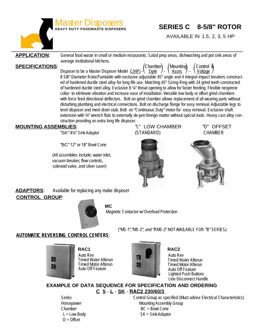
APPLICATION: General food waste in small or medium restaurants. Salad prep areas, dishwashing and pot sink areas ofaverage institutional kitchens.
SPECIFICATIONS: Chamber Mounting Control &Disposer to be a Master Disposer Model C(HP) - Style - Assm. - Voltage8 5/8" Diameter Rotor/Turntable with exclusive adjustable 45° angle and 4 integral impact breakers construct-ed of hardened ductile steel alloy for long life use. Matching 45° Sizing Ring with 24 grind teeth constructedof hardened ductile steel alloy. Exclusive 8 ¼" throat opening to allow for faster feeding. Flexible neoprenecollar to eliminate vibration and increase ease of installation. Versatile low body or offset grind chamberswith force feed directional deflectors. Bolt on grind chamber allows replacement of all wearing parts withoutdisturbing plumbing and electrical connections. Bolt on discharge flange for easy removal. Adjustable legs tolevel disposer and meet drain stub. Bolt on “Continuous Duty” motor for easy removal. Exclusive shaftextension with ¾" wrench flats to externally de-jam foreign matter without special tools. Heavy cast alloy con-struction providing an extra long life disposer.
MOUNTING ASSEMBLIES: "L" LOW CHAMBER "O" OFFSET"SK" 8¼" Sink Adaptor (STANDARD) CHAMBER
"BC" 12" or 18" Bowl Cone
(All assemblies include; water inlet,
( (( )) )
CONTROL GROUP:
RAC1 RAC2Auto RevTimed Water AfterunTimed Motor AfterunAuto Off Feature
Auto Rev
Timed Motor AfterunTimed Water Afterun
Auto Off FeatureLighted Push ButtonsLine Disconnect Handle
O = Offset
MCMagnetic Contactor w/ Overload Protection
HEAVY DUTY FOODWASTE DISPOSERS SERIES C 8-5/8" ROTOR
("MS-1","MS-2", and "RMS-2" NOTAVAILABLE FOR "B" SERIES.)OMATIC REVERSING CONTROL CENTERS:
ADAPTORS: Available for replacing any make disposer
vacuum breaker, flow controls, solenoid valve, and silver saver)
5 - L - SK - RAC2 230/60/3
Master DisposersAVAILABLE IN 1.5, 2, 3, 5 HP

SERIES "C" INSTALLATION DATA AND DIMENSIONS
TYPICAL INSTALLATION8¼" SINK ADAPTOR ‘SK’
MOTOR DATA
HP PH Voltage Amps.
1½ 1 115/230 18.0/9.01½ 3 208-230/460 6.4/3.22 3 208-230/460 7.0/3.53 3 208-230/460 10.5/5.255 3 208-230/460 17.0/8.57½ 3 208-230/460 22.0/11.010 3 208-230/460 26.0/13.0
DISPOSER PLUMBINGINLET: ¾" cold water supply at 20lbs. minimum flow pressure.OUTLET: 2" female std. thread pipecoupling. Connect directly to drain,not thru grease trap.DRAIN: Min. slope ¼" per foot.Use recessed thread fitting w/pipeends reamed/burr-free. Use shorthorizontal line w/ elbows and teesat minimum, using only long-sweeptype. Connected to 3" branch linerunning into stack.IMPORTANT: Rod and clean drainbefore using disposer, even in anew installation.
DIMENSIONS
NOTE:ALL ELECTRICAL AND PLUMBINGCONNECTIONS SHOULD BEMADE ACCORDING TO LOCALAND AREA CODES.
SUGGESTED DRAINLINE CONNECTION
2" WASTE LINE
CLEAN-OUT
P-TRAP
DISPOSERFLANGE
All dimensions are for “L” Low ChamberFor “O” Offset Chamber, consult factory.
8¼" SINK ADAPTOR ‘SK’ 18" BOWL / CONE ‘BC’
CUTOUT 9¼"
CUTOUT 19 "
22" MIN.
10"STD. 8½"
TO CENTER
TO CENTER
9"
29½" MIN.
7½"
10"STD. 8½"
TO CENTER
9"TO CENTER
EXTRA LENGTH NEOPRENECONNECTION SLEEVE. MAYBE CUT FOR CORRECT FIT.
OUTLET MAY FACEANY DIRECTION ASBASE ROTATES 360°
CUTOUT 9¼ "
22" MIN.
10"STD. 8½"
TO CENTER
9"
TO CENTER
UNION
½" FLOWCONTROL
¾" SOLENOID
¾" VACUUMBREAKER
CONTROLSAS SPECIFIED
Continuous Duty-Dual Voltageand Dual Direction-1750 RPM-60CY Motors. Full service factor-inaccordance with NEMA & NECelectrical codes. Bearings per-manently lubricated.
¾" FLOWCONTROL(BUSHED ½")
2" NPT
SHADED SUPPLIED BY OTHERS
Master DisposersSOMAT COMPANY165 Independence Court, Lancaster, PA 17601717-397-5100 — FAX #717-299-4131800-237-6628 ext. 173 — www.masterdisposers.com

APPLICATION: Salad prep areas and areas of small volume and light waste.
SPECIFICATIONS: Chamber Mounting Control &Disposer to be a Master Disposer Model D(HP) - Style - Assm. - Voltage6" Diameter Rotor/Turntable with 2 integral impact breakers constructed of hardened ductile steel alloy forlong life use. Matching Sizing Ring with 20 grind teeth constructed of hardened ductile steel alloy. 4 3/4"throat opening. Low body chamber with force feed directional deflectors. Bolt on grind chamber for ease ofremoving disposer during servicing. Cast in discharge flange. Water inlet in waste chamber wall. Bolt on"Continuous Duty" motor for easy removal. Exclusive shaft extension with 1/2" wrench flats to externally de-jam foreign matter without special tools. Heavy cast alloy construction providing an extra long life disposer.
MOUNTING ASSEMBLIES: "L" LOW CHAMBER
"SK" 8¼" Sink Adaptor
"BC" 12" or 18" Bowl Cone
AUTOMATIC REVERSING PREFABRICATED CONTROL CENTERS:
EXAMPLE OF DATA SEQUENCE FOR SPECIFICATION AND ORDERINGD
Series Control Group as specified (Must advise Electrical Characteristics)Horsepower Mounting Assembly GroupChamber BC = Bowl ConeL = Low Body STD. SK = Sink Adaptor
( (( )) )
CONTROL GROUP:
HEAVY DUTY FOODWASTE DISPOSERSSERIES D 6" ROTOR
"SK" 4¾" Sink Adaptor (ST ANDARD)INCLUDES: Vacuum Breaker, Flow Control, Stopper, and Solenoid Valve
INCLUDES: Vacuum Breaker, Flow Control, Silver Saver, and Solenoid Valve
INCLUDES: Vacuum Breaker, Flow Control, Silver Saver, Water Inlet, and Solenoid Valve
MS SERIES
(Non-Reversing)
MC SERIESManual On/Off Switch Magnetic Starter
(Non-Reversing)
ADAPTORS: Available for replacing any make disposer
RMS SERIESDrum Switch
(Manual-Reversing)
RAC1 RAC2Auto RevTimed Water AfterunTimed Motor AfterunAuto Off Feature
Auto RevTimed Water AfterunTimed Motor AfterunAuto Off FeatureLighted Push ButtonsLine Disconnect Handle
AVAILABLE IN 1, 2 HP
1 - L - SK - RAC2 230/60/3
Master Disposers

SERIES "D" INSTALLATION DATA AND DIMENSIONS
TYPICAL INSTALLATION4¾" SINK ADAPTOR ‘SK’
MOTOR DATA
HP PH Voltage Amps.
1 1 115/230 13.2/6.61 3 208-230/460 4.2/2.12 1 115/230 19.0/9.52 3 208-230/460 6.0/3.0
DISPOSER PLUMBING"
lbs. minimum flow pressure.OUTLET: 1½" female std. threadpipe coupling. Connect directly todrain, not thru grease trap.DRAIN: Min. slope ¼" per foot.Use recessed thread fitting w/pipeends reamed/burr-free. Use shorthorizontal line w/ elbows and teesat minimum, using only long-sweeptype. Connected to 2" branch linerunning into stack.IMPORTANT: Rod and clean drainbefore using disposer, even in anew installation.
DIMENSIONS
NOTE:ALL ELECTRICALAND PLUMBINGCONNECTIONS SHOULD BEMADE ACCORDING TO LOCALAND AREA CODES.
SUGGESTED DRAINLINE CONNECTION
1½" WASTE LINE
CLEAN-OUT
P-TRAP
DISPOSERFLANGE
8¼" SINK ADAPTOR ‘SK’ 12" BOWL / CONE ‘BC’
CUTOUT 9¼ "CUTOUT 13 "
8"
SeeDimension Chart
13¼"
SeeDimension Chart
3½" TO 4" STANDARDSINK OPENING
8" UNION
½" SOLENOID
STARTER As specified
Continuous Duty-Dual Voltage DualDirection and overload protection inmotor 1750 RPM-60 CY Motors. Fullservice factor-in accordance withNEMA & NEC electrical codes.Bearings permanently lubricated.
½" FLOWCONTROL
SeeDimension Chart
18" CONE AVAILABLE-ORDER "BC18"-CUTOUT 19"-Dimension from topof cone to C/L of dis-charge is 15"
DIMENSIONS3 PHASE
H.P. Heights
1 9.75"
2 10.5"1 PHASE
H.P. Height
1 9.75"
2 12.0"BOTTOM OF SHAFT
EXTENSION TO CENTERLINEOF DISCHARGE
7½"7½"
1½" NPT
SHADED SUPPLIED BY OTHERS
Master DisposersSOMAT COMPANY165 Independence Court, Lancaster, PA 17601717-397-5100 — FAX #717-299-4131800-237-6628 ext. 173 — www.masterdisposers.com
½" VACUUM BREAKER
INLET: ¾ cold water supply at 20

RAC1 & RAC2SERIES
AUTOMATIC REVERSINGMAGNETIC CONTROLS
■ APPLICATION: Provides automatic reversing of motor (themotor runs in the opposite direction each time it is started) whichdoubles the life of the shattering mechanism.
■ DESIGN AND CONSTRUCTION: High strength compressionmolded glass fiber reinforced polyester, NEMA4X (watertight,corrosion resistant) enclosure. Reversing magnetic contactors withbuilt-in automatic reset overload relays to protect against lowvoltage, overloads and phase failure. Clearly marked terminalstrip for easy connection of incoming power, solenoid valve andremote switch.
■ DESIGN FEATURES: Encapsulated solid state control circuitboard with self-diagnostic circuitry and indicator lights. Frontmounted, heavy duty Start and Stop pushbuttons. RAC2 Seriesfeatures illuminated pushbuttons to indicate mode of operation,built-in clean out cycle (2 minute time delay for flushing ofdisposer and waste lines) and disconnect switch with heavy dutyfront mounted “pistol grip” handle with provision for lockout. Anti-plug relay to prevent motor reversing while running or coasting.
■ The Eco-Mizer™ Electricity and Water Saver conserves waterand electricity usage by limiting disposer run time to a presetinterval. Specify 5 to 15 minutes.
■ WARRANTY: One full year from date of purchase by end user oreighteen months from date of shipment from factory, coveringdefects in material or workmanship; parts and labor included.
PRODUCT INFORMATION:
OPTIONS:■ PF: Positive flush.■ RS: Remote Start/Stop switch.■ EM: The Eco-Mizer™ Electricity and Water Saver.
RAC2
RAC1
SOMAT COMPANY165 Independence Court, Lancaster, PA 17601
Master Disposers
717-397-5100 — FAX #717-299-4131800-237-6628 ext. 173 — www.masterdisposers.com
√ - used for "D" series only * - Indicate voltage by addind L or H to the end of model number.
RAC1-10* RAC2-10* 10 208/230 460 3RAC1-7* RAC2-7* 7.5 208/230 460 3
√ RAC1-2* √ RAC2-2*√ RAC1-1* √ RAC2-1*
1 115 230 1√ RAC1-0* √ RAC2-0*
RAC1 Series RAC2 Series Range L H PH
Voltages*
RAC 1RAC 2MODELS
Consultant/Contractors Approval
Model No. Model No. H.P.
1 & 2 208/230 460 3RAC1-1.5* RAC2-1.5* 1.5 & 2 208/230 460 3
RAC1-5* RAC2-5* 3 to 5 208/230 460 3RAC1-2.5* RAC2-2.5* 1.5 115 230 1
2 115 230 1
HEAVY DUTY FOODWASTE DISPOSERSMaster Disposers

MODELS RAC1 & RAC2AUTOMATIC REVERSING MAGNETIC CONTROLS
■ BID SPECIFICATIONS: (Example)
Item No. Control Center
Construction: Shall be NEMA4X watertight, corrosion resistant, molded glass fiber reinforced polyester enclosure. Reversingmagnetic contactors with overload relay to protect against low voltage, motor overload and phase failure. Front mountedheavy duty illuminated pushbuttons. Built in front-mounted disconnect switch with heavy duty pistol grip handle with provisionfor lockout. Encapsulated (moisture resistant) solid state low voltage control circuit with self diagnostic indicator lights. Anti-plug relay to prevent motor reversing while running or coasting. Clean out cycle 2 minute time delay. Shall include the Eco-Mizer™ Electricity and Water Saver preset at factory to customer requirements, 5 to 15 minutes, at no additional cost.
Approvals and Warranty: Shall be UL (Underwriters Laboratories, Inc.) listed. Warranty shall cover parts, labor andmileage on all components for one year.
■ OPTIONS:
Additional Cost
■ SHIPPING DIMENSIONS AND WEIGHTS:WIDTH DEPTH HEIGHT WEIGHT VOLUME
MODEL NO. in. mm in. mm in. mm lbs. kg cu. ft. cu. mRAC1 12 305 14 356 11 279 25 11 1.1 .03RAC2 12 305 14 356 11 279 28 13 1.1 .03
MODEL RS: REMOTE START/STOP SWITCHAllows control panel to be located a distance awaywhile Start/Stop switch can be mounted neardisposer. NEMA4X enclosure.
MODEL PF: POSITIVE FLUSHLeaves water running for flushingof waste chamber and drainline for two minutes after motor stops.
■ DIMENSIONS: ■ TYPICAL INSTALLATION:
33⁄8”
53⁄4”
FRONT VIEW
43⁄8”
SIDE VIEW BACK VIEW
23⁄4”
5⁄16”
13⁄16”
41⁄8”
135⁄16”
115⁄16” 71⁄2” (RAC2 SERIES ONLY)
123⁄4”
5⁄16” DIA. (4)MOUNTING
HOLESRIGHT SIDE VIEWFRONT VIEW
HINGE THIS SIDE63⁄8”
8”
BOTTOM VIEW
OPTIONAL REMOTE START/STOPSWITCH (SEE BELOW)
COLDWATERSUPPLY
POWERSUPPLY
SOMAT COMPANY165 Independence Court, Lancaster, PA 17601
RAC2-5L
Master Disposers is not responsible for any typographical errors. Due to continued product improvement specifications are subject to change without prior notice.
Master Disposers
717-397-5100 — FAX #717-299-4131800-237-6628 ext. 173 — www.masterdisposers.com
Control Center shall be Master Disposer model

SOMAT COMPANY165 Independence Court, Lancaster, PA 17601
MODEL MC
MCSERIES
MAGNETIC STARTER(NON-REVERSING)
■ APPLICATION: Provides magnetic contactor control of motor forlonger switch life.
■ DESIGN AND CONSTRUCTION: High strength compression moldedNEMA4X (watertight, corrosion resistant) enclosure. Magneticcontactor with built-in automatic reset overload relay to protectagainst low voltage, overloads and phase failure. Clearly markedterminal strip for easy connection of incoming power, solenoid valveand remote switch.
■ WARRANTY: One full year from date of purchase by end user oreighteen months from date of shipment from factory, covering defectsin material or workmanship; parts and labor included.
PRODUCT INFORMATION:
Model No. H.P. Voltage Phase
MC-1L
MC-1H
MC-5L
MC-5H
Canadian StandardsAssociation Listed
ITEM NO.__________________
LISTED
1 to 2 115 1
1 to 2 230 1
For all Master Disposers series.
HEAVY DUTY FOODWASTE DISPOSERS
Master Disposers
717-397-5100 — FAX #717-299-4131800-237-6628 ext. 173 — www.masterdisposers.com
1 to 10 230 3
1 to 10 460 3
Master Disposers

MODEL MCMAGNETIC STARTER (NON-REVERSING)
Canadian StandardsAssociation ListedLISTED
800-237-6628 ext. 173 — www.masterdisposers.com717-397-5100 — FAX #717-299-4131
Master Disposers
165 Independence Court, Lancaster, PA 17601SOMAT COMPANY
Master Disposers is not responsible for any typographical errors. Due to continued product improvement specifications are subject to change without prior notice.

RMSSERIES
MANUAL REVERSINGDRUM SWITCH
■ APPLICATION: Provides manually operated reversing of disposerwhich doubles the life of impact bars and sizing ring. Use whenmagnetic contactor and overload protection are not required.
■ DESIGN AND CONSTRUCTION: NEMA4, watertight paintedenclosure. Durable steel activating lever with positive stops forforward and reverse positions.
■ WARRANTY: One full year from date of purchase by end user oreighteen months from date of shipment from factory, covering defectsin material or workmanship; parts and labor included.
PRODUCT INFORMATION:
Consultant/Contractors Approval
Canadian StandardsAssociation Listed
Model No. Voltage Phase H.P.
115 1
208-230/460 3
ITEM NO.__________________
LISTED
SOMAT COMPANY165 Independence Court, Lancaster, PA 17601
800-237-6628 ext. 173 — www.masterdisposers.com717-397-5100 — FAX #717-299-4131
Master Disposers
For “D” series disposers only.
HEAVY DUTY FOODWASTE DISPOSERSMODEL RMS-2
RMS-2 230 1
1 to 2
1 to 2
1 to 2
Master Disposers
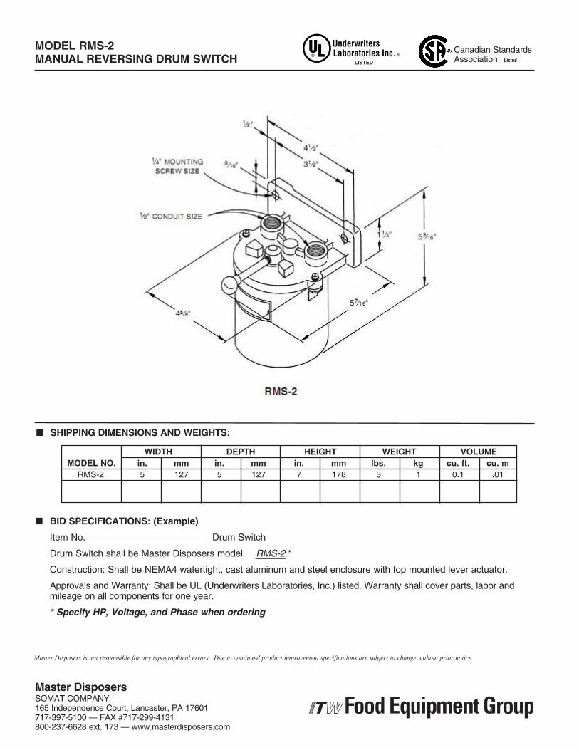
MANUAL REVERSING DRUM SWITCH
■ BID SPECIFICATIONS: (Example)
Item No. Drum Switch
Construction: Shall be NEMA4 watertight, cast aluminum and steel enclosure with top mounted lever actuator.
Approvals and Warranty: Shall be UL (Underwriters Laboratories, Inc.) listed. Warranty shall cover parts, labor andmileage on all components for one year.
* Specify HP, Voltage, and Phase when ordering
■ SHIPPING DIMENSIONS AND WEIGHTS:
WIDTH DEPTH HEIGHT WEIGHT VOLUMEMODEL NO. in. mm in. mm in. mm lbs. kg cu. ft. cu. m
RMS-2 5 127 5 127 7 178 3 1 0.1 .01
Canadian StandardsAssociation ListedLISTED
SOMAT COMPANY165 Independence Court, Lancaster, PA 17601
Drum Switch shall be Master Disposers model
Master Disposers
717-397-5100 — FAX #717-299-4131800-237-6628 ext. 173 — www.masterdisposers.com
Master Disposers is not responsible for any typographical errors. Due to continued product improvement specifications are subject to change without prior notice.
RMS-2.*
MODEL RMS-2

MODELS
MSSERIES
MANUAL ON/OFF SWITCH(NON-REVERSING)
■ APPLICATION: Economical non-reversing On/Off switch for use whenmagnetic contactor and overload protection are not required.
■ DESIGN AND CONSTRUCTION: NEMA4, watertight, cast aluminumhousing and cover. Cast aluminum lever actuator with provision forlockout.
■ WARRANTY: One full year from date of purchase by end user oreighteen months from date of shipment from factory, covering defectsin material or workmanship; parts and labor included.
PRODUCT INFORMATION:
Consultant/Contractors Approval
Model No. H.P. Voltage Phase
MS-1
MS-2
MS-1MS-2
ITEM NO.__________________
LISTED
For "D" series disposers only
1 to 2 208, 230 or 460 3
1 to 2 115 or 230 1
HEAVY DUTY FOODWASTE DISPOSERS
800-237-6628 ext. 173 — www.masterdisposers.com717-397-5100 — FAX #717-299-4131
Master Disposers
165 Independence Court, Lancaster, PA 17601SOMAT COMPANY
Master Disposers

MODELS MS-1 & MS-2MANUAL ON/OFF SWITCH (NON-REVERSING)
■ BID SPECIFICATIONS: (Example)
Item No. Manual Switch
Construction: Shall be NEMA4 watertight, cast aluminum enclosure wtih lever actuator and lock out provisions.
Approvals and Warranty: Shall be UL (Underwriters Laboratories, Inc.) listed. Warranty shall cover parts, labor andmileage on all components for one year.
* Specify HP, Voltage, and Phase when ordering
■ SHIPPING DIMENSIONS AND WEIGHTS:
WIDTH DEPTH HEIGHT WEIGHT VOLUMEMODEL NO. in. mm in. mm in. mm lbs. kg cu. ft. cu. m
MS-1 7 178 7 178 3 76 4 2 .09 .002MS-2 7 178 7 178 3 76 4 2 .09 .002
3/4" [19 mm]
51/4"[133 mm]
3 7/16"[87 mm]
21/8"[54 mm]
3/4" NPT
3"[76 mm]
ø 5/16"[ø 8 mm]
LISTED
MS-2.*Manual Switch shall be model
Master Disposers is not responsible for any typographical errors. Due to continued product improvement specifications are subject to change without prior notice.
800-237-6628 ext. 173 — www.masterdisposers.com717-397-5100 — FAX #717-299-4131
Master Disposers
165 Independence Court, Lancaster, PA 17601SOMAT COMPANY

Item No. Part No.
1 SCREWS/Waste Chamber (6)
2 GASKET/Sizing Ring
3 SIZING RING
4 SCREW/Center Breaker
5 CENTER BREAKER
6 GASKET/Center Breaker
7 ROLL PIN
8 ROTOR TURNTABLE
9 LIP SEAL/Rotor Turntable
10 LIP SEALS/Motor Shaft (2)
11 GASKET/Seal Housing
12 SLINGER/Motor Shaft
13 GASKET/Discharge Flange
14 CLAMPS/Sleeve (2)
15 SLEEVE - Connector
16 WASTE CHAMBER - L.B.
17 SEAL HOUSING
18 SCREWS/Seal Housing (4)
19 KEY
20 DISCHARGE FLANGE
21 SCREWS/Flange (2)
22 SCREWS/Motor (4)
23 LEG (3)
24 BOWL
MOTOR OPTIONS
- 3 HP / 3 PH
- 5 HP / 3 PH
- 7.5 HP / 3 PH
- 10 HP / 3 PH
LOWER MOTOR BEARING
UPPER MOTOR BEARING
SEAL AND GASKET KIT
- INCLUDES ITEMS
2, 6, 9, 10, 11, 20, GREASE
COMPLETE RENEWAL KIT
- INCLUDES ITEMS
1, 2, 3, 4, 5, 6, 7, 8, 9, 10, 11,
12, 13, GREASE
A-4100
D-280
D-1272
A-4200
A-1288
A-1022
A-4201
D-1287N
D-1009
A-1011
A-019
A-016
A-161
A-3000
G-554
G-556
D-1008
A-4202
A-1185
A-159
A-4120
A-2213
09-BC-927
G-247
02-BC-033
02-ABC-053
02-ABC-723
02-ABC-103
B-SGK-NS
B-CRK-NS
Numbers in parenthesis are total required quantities
HEAVY DUTY FOODWASTE DISPOSERS
PARTS BREAKDOWN
CLAMP/Sleeve (1) A-3000
CHAMBER G-299
GASKET/Plate D-158
ADAPTER PLATE D-162
ADAPTER RING D-056
SERIES B 10 5/8" ROTOR
Master Disposers
OFF-SET
with 3/4with 3/4 wrench flats wrench flatsMotor shaft (end-view)
02-BC-40102-BC-402

SERIES “B” PROCEDURE FOR COMPLETE PARTS REPLACEMENT DISASSEMBLY
REMOVE PARTS IN THE FOLLOWING ORDER
STEP ITEM A CLAMPS/Sleeve (two). Only lower clamp may require removal 14 B SCREWS/Waste Chamber (six). 1 C WASTE CHAMBER. 16 D GASKET/Sizing Ring 2 E SIZING RING — Pry upward, uniformly around flange, to 3 avoid cocking. F SCREW/Center Breaker — Hold 3/4” flats on shaft extension 4 Beneath motor, with wrench or vise-grip and remove screw G CENTER BREAKER. Winged Casting with ROLL PIN 5, 7 H GASKET/Center Breaker 6 I KEY — Extra length, extended above shaft, permits gripping 19 J ROTOR TURNTABLE. Grip shaft extension and turn Rotor 8 counterclockwise. L LIP SEAL. Remove for counterbore of Impact Hub (22). 9 M SCREWS/Seal Housing (four). 18 N SEAL HOUSING. Remove with rotating, upward movement. 17 N LIP SEALS/Motor Shaft (two). Remove from counterbore 10 in Seal Housing. O GASKET/Seal Housing. 11 At this disassembly-point, clean, polish, and inspect shaft in seal area. To service motor, remove 4 Screws (22). Mark junction box location to facilitate repositioning . Install new replacement Slinger (12) on motor shaft. Before re-installing motor, thoroughly clean counterbore for motor-flange.
REASSEMBLY REASSEMBLE DISPOSER COMPONENTS IN FOLLOWING ORDER
STEP ITEM A GASKET/Seal Housing. Thoroughly clean surface for 11 gasket seating. B LIP-SEALS/Motor Shaft (two). Pack each seal cavity with 10 waterproof grease. With open sides up, press in greased housing counterbore C SEAL HOUSING. Press on shaft with rotating downward 17 motion, positioning housing well home on gasket. Secure w/ socket head SCREWS/Seal Housing (four) 18 D LIP SEAL. Position in Rotor Turntable counterbore with open 9 side facing out. Fill Rotor Turntable cavity with grease. E ROTOR TURNTABLE. Grip 3/4” wrench-flats on shaft 8 extension beneath the motor, and screw (clockwise) onto the threaded shaft. F SIZING RING — Insert in Bowl (24), applying even pressure 3 around the Ring to avoid cocking. The angular gap between Rotor Turntable and Sizing Ring should be approximately .030”, with Sizing Ring firmly down on Bowl (24). Adjust gap by raising or lowering Rotor. G KEY — After gap is set, align shaft keyway with nearest slot 19 in the Rotor Turntable, and insert key. Original key length must be used, as key extension is needed to grip key in removal. H GASKET/Center Breaker 6 I CENTER BREAKER. Place on gasket. Align Roll Pin with 5, 7 hole in gasket and Rotor Turntable. J SCREW/Center Breaker — Tighten securely, gripping 4 the shaft extension beneath motor. K GASKET/Sizing Ring. Position greased gasket, centered 2 on Sizing Ring. L CHAMBER. Place on Sizing Ring Gasket, with matching 16 screw holes aligned. M SCREWS/Chamber (six) Start all screws. Re-check Ring 1 gasket position. Tighten screws alternately. N CLAMPS/Sleeve (two) Position Sleeve (15) on chamber and 14 secure clamps
Master DisposersSOMAT COMPANY165 Independence Court, Lancaster, PA 17601717-397-5100 — FAX #717-299-4131800-237-6628 ext. 173 — www.masterdisposers.com

Item No. Part No.
1 SCREWS/Waste Chamber (6)
2 GASKET/Sizing Ring
3 SIZING RING
4 SCREW/Center Breaker
5 CENTER BREAKER
6 GASKET/Center Breaker
7 ROLL PIN
8 ROTOR TURNTABLE
9 LIP SEAL/Rotor Turntable
10 LIP SEALS/Motor Shaft (2)
11 GASKET/Seal Housing
12 SLINGER/Motor Shaft
13 GASKET/Discharge Flange
14 CLAMPS/Sleeve (2)
15 SLEEVE - Connector
16 WASTE CHAMBER - L.B.
17 SEAL HOUSING
18 SCREWS/Seal Housing (4)
19 KEY
20 DISCHARGE FLANGE
21 SCREWS/Flange (2)
22 SCREWS/Motor (4)
23 LEG (3)
24 BOWL
MOTOR OPTIONS
- 1.5 HP / 1 PH
- 1.5 HP / 3 PH
- 2 HP / 3 PH
- 3 HP / 3 PH
- 5 HP / 3 PH
LOWER MOTOR BEARING
UPPER MOTOR BEARING
SEAL AND GASKET KIT
- INCLUDES ITEMS
2, 6, 9, 10, 11, 20, GREASE
COMPLETE RENEWAL KIT
- INCLUDES ITEMS
1, 2, 3, 4, 5, 6, 7, 8, 9, 10, 11,
12, 13, GREASE
A-4100
D-316-A
D-1294
A-4200
A-1288
A-1022
A-4201
D-1293N
D-1009
A-1011
A-019
A-016
A-161
A-3000
G-554
G-555
D-1008
A-4202
A-1185
A-159
A-4120
A-2213
09-BC-927
R-154
02-C-121
02-C-123
02-C-023
02-BC-033
02-ABC-053
02-BC-401
02-BC-402
C-SGK-NS
C-CRK-NS
Numbers in parenthesis are total required quantities
SERIES C 8 5/8" ROTORHEAVY DUTY FOODWASTE DISPOSERS
PARTS BREAKDOWN
Master Disposers
CHAMBER G-155
CLAMP/Sleeve (1) A-3000
GASKET/Plate D-158
ADAPTER PLATE D-162
ADAPTER RING D-056OFF-SET
with 3/4with 3/4 wrench flats wrench flatsMotor shaft (end-view)

DISASSEMBLY REMOVE PARTS IN THE FOLLOWING ORDER
STEP ITEM A CLAMPS/Sleeve (two). Only lower clamp may require removal 14 B SCREWS/Waste Chamber (six). 1 C WASTE CHAMBER. 16 D GASKET/Sizing Ring 2 E SIZING RING — Pry upward, uniformly around flange, to 3 avoid cocking. F SCREW/Center Breaker — Hold 3/4” flats on shaft extension 4 Beneath motor, with wrench or vise-grip and remove screw G CENTER BREAKER. Winged Casting with ROLL PIN 5, 7 H GASKET/Center Breaker 6 I KEY — Extra length, extended above shaft, permits gripping 19 J ROTOR TURNTABLE. Grip shaft extension and turn Rotor 8 counterclockwise. L LIP SEAL. Remove for counterbore of Impact Hub (22). 9 M SCREWS/Seal Housing (four). 18 N SEAL HOUSING. Remove with rotating, upward movement. 17 N LIP SEALS/Motor Shaft (two). Remove from counterbore 10 in Seal Housing. O GASKET/Seal Housing. 11 At this disassembly-point, clean, polish, and inspect shaft in seal area. To service motor, remove 4 Screws (22). Mark junction box location to facilitate repositioning . Install new replacement Slinger (12) on motor shaft. Before re-installing motor, thoroughly clean counterbore for motor-flange.
REASSEMBLY REASSEMBLE DISPOSER COMPONENTS IN FOLLOWING ORDER
STEP ITEM A GASKET/Seal Housing. Thoroughly clean surface for 11 gasket seating. B LIP-SEALS/Motor Shaft (two). Pack each seal cavity with 10 waterproof grease. With open sides up, press in greased housing counterbore C SEAL HOUSING. Press on shaft with rotating downward 17 motion, positioning housing well home on gasket. Secure w/ socket head SCREWS/Seal Housing (four) 18 D LIP SEAL. Position in Rotor Turntable counterbore with open 9 side facing out. Fill Rotor Turntable cavity with grease. E ROTOR TURNTABLE . Grip 3/4” wrench-flats on shaft 8 extension beneath the motor, and screw (clockwise) onto the threaded shaft. F SIZING RING — Insert in Bowl (24), applying even pressure 3 around the Ring to avoid cocking. The angular gap between Rotor Turntable and Sizing Ring should be approximately .030”, with Sizing Ring firmly down on Bowl (24). Adjust gap by raising or lowering Rotor. G KEY — After gap is set, align shaft keyway with nearest slot 19 in the Rotor Turntable, and insert key. Original key length must be used, as key extension is needed to grip key in removal. H GASKET/Center Breaker 6 I CENTER BREAKER. Place on gasket. Align Roll Pin with 5, 7 hole in gasket and Rotor Turntable. J SCREW/Center Breaker — Tighten securely, gripping 4 the shaft extension beneath motor. K GASKET/Sizing Ring. Position greased gasket, centered 2 on Sizing Ring. L CHAMBER. Place on Sizing Ring Gasket, with matching 16 screw holes aligned. M SCREWS/Chamber (six) Start all screws. Re-check Ring 1 gasket position. Tighten screws alternately. N CLAMPS/Sleeve (two) Position Sleeve (15) on chamber and 14 secure clamps
Master DisposersSOMAT COMPANY165 Independence Court, Lancaster, PA 17601717-397-5100 — FAX #717-299-4131800-237-6628 ext. 173 — www.masterdisposers.com
SERIES “C” PROCEDURE FOR COMPLETE PARTS REPLACEMENT

1 SCREWS/Waste Chamber (6)
2 GASKET/Sizing Ring
3 SIZING RING
4 SCREW/Center Plate
5 CENTER PLATE
6 GASKET/Center Plate
7 ROTOR TURNTABLE
8 GASKET: MOTOR/BASE
9 LIP SEAL
10 LIP SEALS/Motor Shaft (2)
11 SLINGER/Motor Shaft
12 WASTE CHAMBER
13 PLUG
14 SPLASHGUARD/GASKET
15 SCREWS/Head (4)
16 SET-SCREWS/Sizing Ring(2)
17 KEY
18 SCREWS/Motor (4)
19 BOWL
20 HEAD-Casting
21 CUP-Stainless
22 GASKET-Fiber
23 GASKET-Vinyl
24 STOPPER
MOTOR OPTIONS
- 1 HP / 1 PH
- 1 HP / 3 PH
- 2 HP / 1 PH
- 2 HP / 3 PH
LOWER MOTOR BEARING
UPPER MOTOR BEARING
SEAL AND GASKET KIT
- INCLUDES ITEMS
2, 6, 8, 9, 10, GREASE
COMPLETE RENEWAL KIT
- INCLUDES ITEMS
1, 2, 3, 4, 5, 6, 7, 8, 9, 10,
11, GREASE
A-3300
A-906
A-902
A-3400
A-908
A-907
A-901NS
07-HA-5
A-920
A-911A
A-912
A-903
10-5-27
07-H-18
A-3301
A-3309
A-3310
A-2202A
A-900
A-904
27-H-15
07-H-20
07-H-19
06-H-8
02-D-111
02-D-013
02-D-021
02-D-023
D-SGK-NS
D-CRK-NS
Item No. Part No.
Numbers in parenthesis are total required quantities
PARTS BREAKDOWN SERIES D 6" ROTOR
Master DisposersHEAVY DUTY FOODWASTE DISPOSERS
02-5-400M-6305
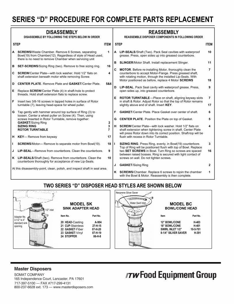
SERIES “D” PROCEDURE FOR COMPLETE PARTS REPLACEMENT DISASSEMBLY
DISASSEMBLE BY FOLLOWING THE STEPS BELOW IN ORDER
STEP ITEM A SCREWS/Waste Chamber. Remove 6 Screws, separating 1 Bowl(19) from Chamber(12). Regardless of style of Head used, there is no need to remove Chamber when servicing unit B SET-SCREWS/Sizing Ring (two). Remove to free sizing ring. 16 C SCREW/Center Plate—with lock washer. Hold 1/2” flats on 4 shaft extension beneath motor while removing Screw. D CENTER PLATE. Remove Plate and GASKET/Center Plate. 5&6 E Replace SCREW/Center Plate (4) in shaft-hole to protect threads. Hold shaft extension flats to replace screw. F Insert two 3/8-16 screws in tapped holes in surface of Rotor turntable (7), leaving head-space for wheel puller. G Tap gently with hammer around top surface of Ring (3) to loosen. Center a wheel puller on Screw (4). Then, using screws Inserted in Rotor Turntable, remove together: GASKET/Sizing Ring 2 SIZING RING 3 ROTOR TURNTABLE 7 H KEY— Remove from keyway 17 I SCREWS/Motor— Remove to separate motor from Bowl(19). 18 J LIP-SEAL—Remove from counterbore. Clean the counterbore. 9 K LIP-SEALS/Shaft (two). Remove from counterbore. Clean the 10 counterbore thoroughly for acceptance of new Lip-Seals. At this disassembly-point, clean, polish, and inspect shaft in seal area.
REASSEMBLY REASSEMBLE DISPOSER COMPONENTS IN FOLLOWING ORDER
STEP ITEM A LIP-SEALS/Shaft (Two). Pack Seal cavities with waterproof 10 grease. Press, open sides up into greased counterbore. B SLINGER/Motor Shaft. Install replacement Slinger. 11 C MOTOR. Before re-installing Motor, thoroughly clean the 7 counterbore to accept Motor-Flange. Press greased shaft, with rotating motion, through the installed Lip-Seals. With Motor positioned as before, replace 4 Motor SCREWS 18 D LIP-SEAL. Pack Seal cavity with waterproof grease. Press, 9 open sides up, into greased counterbore. E ROTOR TURNTABLE —Place on shaft, aligning keyway slots 7 in shaft & Rotor. Adjust Rotor so that the top of Rotor remains slightly above end of shaft. Insert KEY. 17 F GASKET/Center Plate. Place Gasket over center of shaft. 6 G CENTER PLATE . Position the Plate on top of Gasket. 5 H SCREW/Center Plate—with lock washer. Hold 1/2” flats on 4 shaft extension when tightening screw in shaft. Center Plate will press Rotor down into its correct position. Shaft-top will be flush with recess in Rotor Turntable. I SIZING RING. Press Ring, evenly, in Bowl(19) counterbore. 3 Top of Ring will be positioned flush with top of Bowl. Replace two SET SCREWS in Bowl. Turn Ring so screws are spaced 16 between raised bosses. Ring is secured with light contact of screws on wall. Do not tighten screws. J GASKET/Sizing Ring 2 K SCREWS/Chamber. Replace 6 screws to rejoin the chamber 1 with the Bowl & Motor. Reassembly is then complete.
TWO SERIES “D” DISPOSER HEAD STYLES ARE SHOWN BELOW
Adapter fits 3-1/2” to 4” standard sink opening.
1/2” inlet
MODEL SK SINK ADAPTER HEAD
Item No. Part No. 20 HEAD-Casting A-904 21 CUP-Stainless 27-H-15 22 GASKET-Fiber 07-H-20 23 GASKET-Vinyl 07-H-19 24 STOPPER 06-H-8
Water Swirl Inlet
Neoprene Silver Saver
MODEL BC BOWL/CONE HEAD
Item Part No. 12” BOWL/CONE H-403 18” BOWL/CONE H-401 SWIRL INLET 1/2” 10-5-701 8-1/4” SILVER SAVER H-391
800-237-6628 ext. 173 — www.masterdisposers.com717-397-5100 — FAX #717-299-4131165 Independence Court, Lancaster, PA 17601SOMAT COMPANY
Master Disposers

1 2 3 4 5 6 7 8 9
10
11 12
03-5-988 03-5-987 03-5-1023 03-5-1025 03-5-1042 03-5-1034 08-6-258 03-5-1000 03-HAB-940 03-HAB-995 03-HAB-911 03-HAB-912 08-6-250 03-HAB-906 03-BC-907 03-C-909
Pushbutton Assy: Red (N.C.) Pushbutton Assy: Black (N.O.) Legend Plate: “STOP” Legend Plate: “RUN” Enclosure: Non-Metallic, RAC1 & 2 Control Module Screw: Php HD, 8-32 x 1 Wiring Harness: RAC1 Fuse: 2.5 Amp Transformer: 24V/115, 230V 50VA Transformer: 24V/208, 230, 460V 50VA Transformer: 24V/380V 50VA Screw: Php HD, 8-32 x 1/2 Contactor: Rev, 10A, 24V, 50/60HZ (Use w/ 0H, 1.5L, 1.5H, 2L, 2H & 5H) Contactor: Rev, 17.5A, 24V, 50/60HZ (Use w/ 0L, 1H, 2.5H, 5L, 7H & 10H) Contactor: Rev, 32A, 24V, 50/60HZ (Use w/ 1L, 2.5L, 7L & 10L)
13 14 15 16 17
18 19
08-5-949 03-5-983 03-5-1067 03-5-1097 03-5-1002 03-5-1001 03-5-1085 08-6-251 03-5-1124 03-5-1125 03-5-1126 03-5-1127
Screw, Php HD, 10-32 x 1/2 Back Plate: RAC1 & 2 Track: Contactor Mounting Grounding Lug Terminal Strip: 9 Position Terminal Strip: 6 Position Terminal Strip: 13 Position Screw, Php HD, 8-32 x 3/4 Overload Relay: 3-12 Amp (Use with 1.5L, 1.5H & 5H) Overload Relay: 11-16 Amp (Use with 2.5H, 5L, 7H & 10H) Overload Relay: 18-25 Amp (Use with 2.5L & 7L) Overload Relay: 22-32 Amp (Use with 10L)
RAC1 REPLACEMENT PARTS LIST
KEY PART NO. NAME: DESCRIPTION KEY PART NO. NAME: DESCRIPTION
SPECIFY HP, VOLTAGE, PHASE, MODEL AND SERIAL NUMBER WHEN ORDERING CONTACTORS AND OVERLOAD RELAYS.

1 2 3 4 5 6 7 8 9
10 11
12 13 14 15 16
03-5-1036 03-5-1037 03-5-1023 03-5-1025 03-5-1049 03-5-1042 03-5-1034 08-6-258 03-5-999 03-HAB-940 03-HAB-995 03-HAB-911 03-HAB-912 08-6-250 03-5-1120 08-6-251 03-5-1041 03-HAB-906 03-BC-907 03-C-909
Pushbutton Assy: Lighted, Red Pushbutton Assy: Lighted, Amber Legend Plate: “STOP” Legend Plate: “RUN” Handle: Disconnect Switch (w/Shaft) Enclosure: Non Metallic, RAC1 & 2 Control Module Screw: Php HD, 8-32 x 1 Wiring Harness: RAC2 Fuse: 2.5 Amp Transformer: 24V/115, 230V 50VA Transformer: 24V/208, 230, 460V 50VA Transformer: 24V/380V 50VA Screw: Php HD, 8-32 x 1/2 Shaft: Disconnect Switch, RAC2 Screw, Php HD, 8-32 x 3/4 Disconnect Switch: 40 Amp, RAC2 Contactor: Rev, 10A, 24V, 50/60HZ (Use w/ 0H, 1.5L, 1.5H, 2L, 2H & 5H) Contactor: Rev, 17.5A, 24V, 50/60HZ (Use w/ 0L, 1H, 2.5H, 5L, 7H & 10H) Contactor: Rev, 32A, 24V, 50/60HZ (Use w/ 1L, 2.5L, 7L & 10L)
17 18 19 20 21
22
08-5-949 03-5-983 03-5-1067 03-5-1097 03-5-1002 03-5-1001 03-5-1085 03-5-1124 03-5-1125 03-5-1126 03-5-1127
Screw, Php HD, 10-32 x 1/2 Back Plate: RAC1 & 2 Track: Contactor Mounting Grounding Lug Terminal Strip: 9 Position Terminal Strip: 6 Position Terminal Strip: 13 Position Overload Relay: 3-12 Amp (Use with 1.5L, 1.5H & 5H) Overload Relay: 11-16 Amp (Use with 2.5H, 5L, 7H & 10H) Overload Relay: 18-25 Amp (Use with 2.5L & 7L) Overload Relay: 22-32 Amp (Use with 10L
RAC2 REPLACEMENT PARTS LIST
KEY PART NO. NAME: DESCRIPTION KEY PART NO. NAME: DESCRIPTION
SPECIFY HP, VOLTAGE, PHASE, MODEL AND SERIAL NUMBER WHEN ORDERING CONTACTORS AND OVERLOAD RELAYS
1. NATURE OF DOCUMENT. This document constitutes the acceptance of the Master Disposers Division of Somat Company (“Seller”) to sell the products specified on the reverse side (the “Products”) on the terms and conditions contained herein, however, acceptance is made expressly conditional on the Buyer’s agreement to all of the terms and conditions contained herein. Seller’s acceptance of a purchase order from the Buyer shall not constitute acceptance of any of the terms and conditions thereon which differ from these terms, except as the Seller may otherwise specify in writing.2. TERMINATION AND CANCELLATION. Seller shall have the right to terminate and cancel the contract for sale of the Products at any time Seller determines that Buyer’s credit is not satisfactory. Any such termination or cancellation shall be effective upon notification (orally or in writing) to Buyer and shall be without liability to the Seller. Under no circumstances shall Buyer have the right to terminate the contract or cancel its order to purchase the Products, without written authorization by the Seller. All cancelled orders and returned goods will be subject to a minimum of 25% cancellation and/or restocking charge. Custom or modified units cannot be returned. 3. PRICES. Unless otherwise indicated, prices are F.O.B. Lancaster, PA and do not include any sales, use, excise or similar taxes or duties now or hereafter imposed. Errors or omissions in prices are subject to correction.4. PAYMENT. Unless otherwise indicated, payment terms are net cash 30 days from date of shipment. In the event that the Buyer fails to make payment on time, Buyer shall be liable to Seller for the lesser of (a) 1.5% per month on the remaining balance or (b) the highest monthly interest rate which may lawfully be charged to Buyer. Buyer shall be liable for all expenses (including reasonable attorneys’ fees) incurred by Seller in collecting or attempting to collect any amounts due to Seller under the contract.
6. INSPECTION. If, upon receipt of the Products by Buyer at the destination, the same shall appear not to conform to the order, Buyer shall within seven (7) days after receipt thereof, notify Seller of such condition and afford Seller a reasonable opportunity to inspect the Products and make the appropriate adjustments, repair or replacement. The remedies afforded under Section 7 below shall be exclusive for any defects discovered in the Products and which could have been discovered upon inspection. If the Seller is not so notified, the Buyer waives any recourse for those defects, and all warranty obligations of Seller regarding such obvious defects or deficiencies shall terminate.7. LIMITED WARRANTIES AND REMEDIES. Seller warrants that, at the time of shipment, the Products will be free from defects in material and workmanship for a period of one year from the date of purchase by the initial user. Written notice of a claim under this warranty must be received by Seller before the expiration of such period in order for warranty coverage to
If notice of a claim is timely made, Seller will repair or replace the Product or part which is defective (at Seller’s sole option) either at the user’s facility or at Seller’s plant, as Seller shall decide. If Seller decides that a Product or part should be returned to its plant, the Buyer or user shall have the following obligations: (a) removal of any parts to be returned; (b) identification of all parts with tags stating the model number and serial number of the Products on which the part is used; (c) shipment of Products and/or parts, transportation prepaid, to Seller’s plant;
This Warranty shall not apply to the extent that Products or parts have been used other than in conformance with operating or maintenance instructions, subjected to misuse or abuse, damaged by accident, act of God, abnormal use or stress or any other matter unrelated to Seller and beyond its reasonable control or altered or modified by third parties. THIS WARRANTY IS EXCLUSIVE AND IS IN LIEU OF ALL OTHER WARRANTIES, EXPRESS OR IMPLIED, INCLUDING THE IMPLIED WARRANTIES OF MERCHANTABILITY AND FITNESS FOR PURPOSE. IN NO EVENT SHALL THE COMPANY BE LIABLE FOR LOSS OF USE, REVENUE OR PROFIT OR FOR ANY OTHER INCIDENTAL, SPECIAL OR CONSEQUENTIAL DAMAGE INVOLVING THE PRODUCTS.8. LIMITATION OF LIABILITY. The liability of Seller arising out of the manufacture, sale, delivery, repair, or use of any of the Products shall not, in any event, exceed the cost of correcting defects or making replacement as required in the Limited Warranty and, upon the expiration of the Limited Warranty, all liability of Seller to Buyer shall terminate. 9. DELAYS. Neither party shall be liable for any delay or failure to perform any obligation to the other if such delay or failure shall be caused by an event or contingency beyond its reasonable control, irrespective of the nature thereof, however, the delaying party shall endeavor to correct such delay as soon as reasonably practicable. 10. MODIFICATION; ASSIGNMENT; APPLICABLE LAW; ENTIRE AGREEMENT. No modification of the terms and conditions specified in the contract shall be binding upon Seller unless agreed to by Seller in writing. The contract shall not be assigned by Buyer, nor may any of the duties of Buyer there under be delegated, without the written consent of Seller. Any such assignment or delegation without such consent shall be void. The contract shall be governed by, and construed in accordance with, the laws of the State of Pennsylvania. The provisions of the contract shall constitute the entire agreement of the parties with respect to the sale of the Products by Seller to Buyer and shall supersede all prior discussion and writings between the parties. 11. BINDING EFFECT OF CONTRACT. The contract shall be binding upon, and shall inure to the benefit of, the parties hereto and their respective successors and assigns. 12. RETURNS. No returns will be accepted without the prior approval of the Seller. A Return Authorization Number must be given by Seller prior to Products being shipped, freight prepaid, by Buyer. Any damage in transit to Products being returned is Buyer’s responsibility. All accepted returns are subject to a 25% or $25.00 minimum restocking charge. Returns that have been approved by Seller must be received within thirty (30) days after approval. Returns will not be considered after ninety (90) days from date of original notice.
Buyer’s use, misuse, misapplication, failure to inspect, maintain or repair the Products which are the subject of this agreement.14. MINIMUM ORDER. $75.00 net.
TERMS OF SALE
WARRANTY
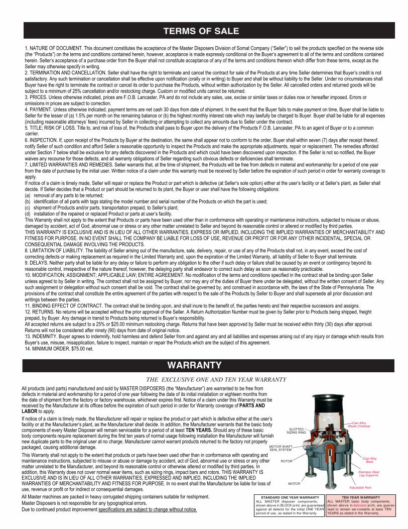
THE EXCLUSIVE ONE AND TEN YEAR WARRANTY
SLOTTEDSIZING RING
MOTOR SHAFTSEAL SYSTEM
MOTOR
Cast AlloyWaste Chamber
Cast AlloyBase
Stainless SteelLeg Supports
Adjustable Feet
STANDARD ONE YEAR WARRANTY
shown above in BLOCK print, are guaranteedagainst all defects for the initial ONE YEARperiod of use, as stated in the Warranty.
shown above in italicized pr int, are guaran-
YEARS as stated in the Warranty.
ALL MASTER basic body components, TEN YEAR WARRANTY
ROTOR
5. TITLE; RISK OF LOSS. Title to, and risk of loss of, the Products shall pass to Buyer upon the delivery of the Products F.O.B. Lancaster, PA to an agent of Buyer or to a common carrier.
apply.
13. INDEMNITY. Buyer agrees to indemnify, hold harmless and defend Seller from and against any and all liabilities and expenses arising out of any injury or damage which results from
Due to continued product improvement specifications are subject to change without notice.
use, revenue or profit or for indirect or consequential damages.WARRANTIES OF MERCHANTABILITY AND FITNESS FOR PURPOSE. In no event shall the Manufacturer be liable for loss of EXCLUSIVE AND IS IN LIEU OF ALL OTHER WARRANTIES, EXPRESSED AND IMPLIED, INCLUDING THE IMPLIED addition, this Warranty does not cover normal wear items, such as sizing rings, impact bars and rotors. THIS WARRANTY IS matter unrelated to the Manufacturer, and beyond its reasonable control or otherwise altered or modified by third parties. In maintenance instructions, subjected to misuse or abuse or damage by accident, act of God, abnormal use or stress or any otherThis Warranty shall not apply to the extent that products or parts have been used other than in conformance with operating and packaged, causing additional damage.new duplicate parts to the original user at no charge. Manufacturer cannot warrant products returned to the factory not properly body components require replacement during the first ten years of normal usage following installation the Manufacturer will furnish
TEN YEARS. Should any of these basic facility or at the Manufacturer’s plant, as the Manufacturer shall decide. In addition, the Manufacturer warrants that the basic body If notice of a claim is timely made, the Manufacturer will repair or replace the product or part which is defective either at the user’s
to apply.LABOR PARTS AND received by the Manufacturer at its offices before the expiration of such period in order for Warranty coverage of
the date of shipment from the factory or factory warehouse, whichever expires first. Notice of a claim under this Warranty must be defects in material and workmanship for a period of one year following the date of its initial installation or eighteen months from
ALL MASTER disposer components,
All products (and parts) manufactured and sold by MASTER DISPOSERS (the “Manufacturer”) are warranted to be free from
All Master machines are packed in heavy corrugated shipping containers suitable for reshipment.Master Disposers is not responsible for any typographical errors.
components of every Master Disposer will remain serviceable for a period of at least
(d) installation of the repaired or replaced Product or parts at user’s facility.
teed to remain serviceable at least TEN