MCWP 4-11.6 Petroleum and Water Logistics Operations · Doctrinal Publication 4, Logistics, and...
74
MCWP 4-11.6 Petroleum and Water Logistics Operations U.S. Marine Corps DISTRIBUTION STATEMENT A: Approved for public release; distribution is unlimited. PCN: 143 000009 00
Transcript of MCWP 4-11.6 Petroleum and Water Logistics Operations · Doctrinal Publication 4, Logistics, and...
MCWP 4-11.6
Petroleum and Water Logistics Operations
U.S. Marine Corps
DISTRIBUTION STATEMENT A: Approved for public release; distribution is unlimited.
PCN: 143 000009 00
To Our Readers
Changes: Readers of this publication are encouraged to submit suggestions and changes thatwill improve it. Recommendations may be sent directly to Commanding General, MarineCorps Combat Development Command, Doctrine Division (C 42), 3300 Russell Road, Suite318A, Quantico, VA 22134-5021 or by fax to 703-784-2917 (DSN 278-2917) or by E-mail [email protected]. Recommendations should include the following information:
l Location of changePublication number and titleCurrent page numberParagraph number (if applicable)Line numberFigure or table number (if applicable)
l Nature of changeAdd, deleteProposed new text, preferably double-spaced and typewritten
l Justification and/or source of change
Additional copies: A printed copy of this publication may be obtained from Marine CorpsLogistics Base, Albany, GA 31704-5001, by following the instructions in MCBul 5600,Marine Corps Doctrinal Publications Status. An electronic copy may be obtained from theDoctrine Division, MCCDC, world wide web home page which is found at the following uni-versal reference locator: https://www.doctrine.usmc.mil.
Unless otherwise stated, whenever the masculine gender is used, both men and women are included.
DEPARTMENT OF THE NAVYHeadquarters United States Marine Corps
Washington, DC 20380-1775
19 June 2005
FOREWORD
Marine Corps Warfighting Publication (MCWP) 4-11.6, Petroleum and Water LogisticsOperations, provides doctrinal guidance for bulk petroleum and water support of the Marineair-ground task force (MAGTF). This publication is aligned doctrinally with Marine CorpsDoctrinal Publication 4, Logistics, and tactically with MCWP 4-1, Logistics Operations. Itspecifically addresses the techniques and procedures of bulk fuel and water support of theMAGTF in a joint/multinational environment. MCWP 4-11.6 is a follow-on publication ofMCWP 3-17, Engineer Operations.
Water and fuel make up the greatest quantities of supply required by the MAGTF to conductmodern warfare. As petroleum or water requirements rise above individual or small unitneeds, it becomes necessary to handle them in “bulk” form. Bulk handling calls for specialequipment, product handling safeguards, and standing operating procedures. Plant account/permanent facilities are often used at bases, camps, and air stations; however, deployingMAGTFs require special expeditionary systems such as the tactical fuel systems. This publi-cation addresses water and fuel as functional operations. For discussion of water and fuel sup-ply classes, see MCWP 4-11.7, MAGTF Supply Operations.
Mission success depends on planning for the known and expecting the unknown. This is espe-cially true when planning bulk liquids operations. Part I discusses bulk fuel operations andpart II discusses bulk water operations. Commanders and their staffs at all levels must be con-cerned about maintaining water and fuel support through completion of the unit’s mission. Toprovide the most effective use of bulk liquids stocks and equipment, bulk liquids plannersmust be familiar with Marine Corps and Department of Defense bulk liquids assets andresponsibilities. To ensure adequate support, commanders and their staffs should address plan-ning for these two commodities in all operation plans.
This publication provides information on the bulk liquids mission, organization, and conceptas well as guidance for the planning and conduct of bulk fuel and water support operations forcommanders, staffs, subordinate commanders, and personnel in bulk liquid units. Applicablelessons learned have been incorporated in this publication.
This publication supersedes MCWP 4-11.6, Bulk Liquids Operations, of 29 August 1996.
Reviewed and approved this date.
BY DIRECTION OF THE COMMANDANT OF THE MARINE CORPS
J. N. MATTISLieutenant General, U.S. Marine Corps
Deputy Commandant for Combat Development
Publication Control Number: 143 000009 00
DISTRIBUTION STATEMENT A: Approved for public release; distribution is unlimited.
PETROLEUM AND WATER LOGISTICS OPERATIONS
TABLE OF CONTENTS
Part I. Bulk Fuel Operations . . . . . . . . . . . . . . . . . . . . . . . . . . . . . . . . . 1-1
Chapter 1. Fundamentals. . . . . . . . . . . . . . . . . . . . . . . . . . . . . . . . . . . . . . . 1-1Developed Theater . . . . . . . . . . . . . . . . . . . . . . . . . . . . . . . . . . . . . . . . . . . . 1-1Undeveloped Theater . . . . . . . . . . . . . . . . . . . . . . . . . . . . . . . . . . . . . . . . . . 1-1Resupply . . . . . . . . . . . . . . . . . . . . . . . . . . . . . . . . . . . . . . . . . . . . . . . . . . . . 1-1Marine Corps Forces . . . . . . . . . . . . . . . . . . . . . . . . . . . . . . . . . . . . . . . . . . 1-1Inland Distribution . . . . . . . . . . . . . . . . . . . . . . . . . . . . . . . . . . . . . . . . . . . . 1-2
Chapter 2. Organization . . . . . . . . . . . . . . . . . . . . . . . . . . . . . . . . . . . . . . . . 2-1Organization and Responsibilities . . . . . . . . . . . . . . . . . . . . . . . . . . . . . . . . 2-1
Defense Energy Support Center . . . . . . . . . . . . . . . . . . . . . . . . . . . . . . 2-1Unified Commands. . . . . . . . . . . . . . . . . . . . . . . . . . . . . . . . . . . . . . . . 2-1Joint Bulk Fuel Support . . . . . . . . . . . . . . . . . . . . . . . . . . . . . . . . . . . . 2-1Joint Task Force . . . . . . . . . . . . . . . . . . . . . . . . . . . . . . . . . . . . . . . . . . 2-2
Military Services . . . . . . . . . . . . . . . . . . . . . . . . . . . . . . . . . . . . . . . . . . . . . 2-2US Army. . . . . . . . . . . . . . . . . . . . . . . . . . . . . . . . . . . . . . . . . . . . . . . . 2-2US Air Force. . . . . . . . . . . . . . . . . . . . . . . . . . . . . . . . . . . . . . . . . . . . . 2-2US Navy . . . . . . . . . . . . . . . . . . . . . . . . . . . . . . . . . . . . . . . . . . . . . . . . 2-3US Marine Corps . . . . . . . . . . . . . . . . . . . . . . . . . . . . . . . . . . . . . . . . . 2-3
Chapter 3. Tactical Fuel Systems . . . . . . . . . . . . . . . . . . . . . . . . . . . . . . . . 3-1Amphibious Assault Fuel System . . . . . . . . . . . . . . . . . . . . . . . . . . . . . . . . 3-1Tactical Airfield Fuel Dispensing System . . . . . . . . . . . . . . . . . . . . . . . . . . 3-3Helicopter Expedient Refueling System . . . . . . . . . . . . . . . . . . . . . . . . . . . 3-3Expedient Refueling System . . . . . . . . . . . . . . . . . . . . . . . . . . . . . . . . . . . . 3-3Six Containers Together . . . . . . . . . . . . . . . . . . . . . . . . . . . . . . . . . . . . . . . . 3-3
Fuel Pump Module . . . . . . . . . . . . . . . . . . . . . . . . . . . . . . . . . . . . . . . . 3-6Fuel Tank Modules. . . . . . . . . . . . . . . . . . . . . . . . . . . . . . . . . . . . . . . . 3-6Accessories . . . . . . . . . . . . . . . . . . . . . . . . . . . . . . . . . . . . . . . . . . . . . . 3-6Cyclic Resupply . . . . . . . . . . . . . . . . . . . . . . . . . . . . . . . . . . . . . . . . . . 3-6
M970 Mobile Refueler . . . . . . . . . . . . . . . . . . . . . . . . . . . . . . . . . . . . . . . . . 3-6Tactical Petroleum Laboratory, Medium . . . . . . . . . . . . . . . . . . . . . . . . . . . 3-6
iv _____________________________________________________________________________________________________ MCWP 4-11.6
USMC Aircraft Bulk Fuel Handling Systems. . . . . . . . . . . . . . . . . . . . . . . . 3-6USMC KC-130R Transport . . . . . . . . . . . . . . . . . . . . . . . . . . . . . . . . . 3-6Tactical Bulk Fuel Distribution System . . . . . . . . . . . . . . . . . . . . . . . . 3-7Aviation Refueling Capability . . . . . . . . . . . . . . . . . . . . . . . . . . . . . . . 3-7
Joint Service Interoperability . . . . . . . . . . . . . . . . . . . . . . . . . . . . . . . . . . . . 3-7US Navy Ship-to-Shore Systems . . . . . . . . . . . . . . . . . . . . . . . . . . . . . 3-7US Army Petroleum System . . . . . . . . . . . . . . . . . . . . . . . . . . . . . . . . . 3-8US Air Force Air-based Petroleum System . . . . . . . . . . . . . . . . . . . . . 3-8
Chapter 4. Bulk Fuel Planning . . . . . . . . . . . . . . . . . . . . . . . . . . . . . . . . . . . 4-1Planning Requirements . . . . . . . . . . . . . . . . . . . . . . . . . . . . . . . . . . . . . . . . . 4-1
Requirements . . . . . . . . . . . . . . . . . . . . . . . . . . . . . . . . . . . . . . . . . . . . 4-1Sourcing and Procurement . . . . . . . . . . . . . . . . . . . . . . . . . . . . . . . . . . 4-1Transportation . . . . . . . . . . . . . . . . . . . . . . . . . . . . . . . . . . . . . . . . . . . . 4-1Storage . . . . . . . . . . . . . . . . . . . . . . . . . . . . . . . . . . . . . . . . . . . . . . . . . 4-1Distribution . . . . . . . . . . . . . . . . . . . . . . . . . . . . . . . . . . . . . . . . . . . . . . 4-1Equipment . . . . . . . . . . . . . . . . . . . . . . . . . . . . . . . . . . . . . . . . . . . . . . . 4-2
Planning Considerations . . . . . . . . . . . . . . . . . . . . . . . . . . . . . . . . . . . . . . . . 4-2Planning for Joint Bulk Fuel Operations. . . . . . . . . . . . . . . . . . . . . . . . . . . . 4-2
Army Petroleum Group. . . . . . . . . . . . . . . . . . . . . . . . . . . . . . . . . . . . . 4-2Compatibility . . . . . . . . . . . . . . . . . . . . . . . . . . . . . . . . . . . . . . . . . . . . 4-2
Marine Corps Bulk Fuel Planning . . . . . . . . . . . . . . . . . . . . . . . . . . . . . . . . 4-2Determine Requirements. . . . . . . . . . . . . . . . . . . . . . . . . . . . . . . . . . . . 4-3Sourcing and Procurement . . . . . . . . . . . . . . . . . . . . . . . . . . . . . . . . . . 4-4Transportation . . . . . . . . . . . . . . . . . . . . . . . . . . . . . . . . . . . . . . . . . . . . 4-4Storage . . . . . . . . . . . . . . . . . . . . . . . . . . . . . . . . . . . . . . . . . . . . . . . . . 4-4Distribution . . . . . . . . . . . . . . . . . . . . . . . . . . . . . . . . . . . . . . . . . . . . . . 4-4
War Reserve Requirements and Stocks . . . . . . . . . . . . . . . . . . . . . . . . . . . . 4-4Petroleum War Reserve Requirement. . . . . . . . . . . . . . . . . . . . . . . . . . 4-4Petroleum War Reserve Stocks. . . . . . . . . . . . . . . . . . . . . . . . . . . . . . . 4-4MEF Petroleum War Reserve Requirement . . . . . . . . . . . . . . . . . . . . . 4-5
Chapter 5. Bulk Fuel Theater Operations . . . . . . . . . . . . . . . . . . . . . . . . . . 5-1Developed Theater . . . . . . . . . . . . . . . . . . . . . . . . . . . . . . . . . . . . . . . . . . . . 5-1
Pipeline System. . . . . . . . . . . . . . . . . . . . . . . . . . . . . . . . . . . . . . . . . . . 5-1Theater Stockage Objectives. . . . . . . . . . . . . . . . . . . . . . . . . . . . . . . . . 5-1
Undeveloped Theater . . . . . . . . . . . . . . . . . . . . . . . . . . . . . . . . . . . . . . . . . . 5-1Minimum Bulk Fuel Stockage Objective . . . . . . . . . . . . . . . . . . . . . . . 5-2Tactical Hose Line . . . . . . . . . . . . . . . . . . . . . . . . . . . . . . . . . . . . . . . . 5-2Air Lines of Communications. . . . . . . . . . . . . . . . . . . . . . . . . . . . . . . . 5-2
Phases of Bulk Fuel Operations . . . . . . . . . . . . . . . . . . . . . . . . . . . . . . . . . . 5-2Development . . . . . . . . . . . . . . . . . . . . . . . . . . . . . . . . . . . . . . . . . . . . . 5-3Lodgment . . . . . . . . . . . . . . . . . . . . . . . . . . . . . . . . . . . . . . . . . . . . . . . 5-3Build-up . . . . . . . . . . . . . . . . . . . . . . . . . . . . . . . . . . . . . . . . . . . . . . . . 5-3
Bulk Fuel Operations Within the MAGTF . . . . . . . . . . . . . . . . . . . . . . . . . . 5-3Command Element . . . . . . . . . . . . . . . . . . . . . . . . . . . . . . . . . . . . . . . . 5-3
Petroleum and Water Logistics Operations _____________________________________________________________________ v
Combat Service Support Element. . . . . . . . . . . . . . . . . . . . . . . . . . . . . 5-4Aviation Combat Element . . . . . . . . . . . . . . . . . . . . . . . . . . . . . . . . . . 5-4Ground Combat Element . . . . . . . . . . . . . . . . . . . . . . . . . . . . . . . . . . . 5-4
Bulk Fuel Support for the MAGTF . . . . . . . . . . . . . . . . . . . . . . . . . . . . . . . 5-5Resupply . . . . . . . . . . . . . . . . . . . . . . . . . . . . . . . . . . . . . . . . . . . . . . . . 5-5Storage . . . . . . . . . . . . . . . . . . . . . . . . . . . . . . . . . . . . . . . . . . . . . . . . . 5-5
Maritime Prepositioning Ships . . . . . . . . . . . . . . . . . . . . . . . . . . . . . . . . . . . 5-5Fuel Offload . . . . . . . . . . . . . . . . . . . . . . . . . . . . . . . . . . . . . . . . . . . . . 5-5Unloading Fuel Systems . . . . . . . . . . . . . . . . . . . . . . . . . . . . . . . . . . . . 5-6
Bulk Fuel Reports . . . . . . . . . . . . . . . . . . . . . . . . . . . . . . . . . . . . . . . . . . . . . 5-7
Chapter 6. Bulk Fuel Inventory Management. . . . . . . . . . . . . . . . . . . . . . . 6-1References. . . . . . . . . . . . . . . . . . . . . . . . . . . . . . . . . . . . . . . . . . . . . . . . . . . 6-1Procedures . . . . . . . . . . . . . . . . . . . . . . . . . . . . . . . . . . . . . . . . . . . . . . . . . . 6-1Fuel Accountability . . . . . . . . . . . . . . . . . . . . . . . . . . . . . . . . . . . . . . . . . . . 6-2Reports . . . . . . . . . . . . . . . . . . . . . . . . . . . . . . . . . . . . . . . . . . . . . . . . . . . . . 6-2
Chapter 7. Bulk Fuel Quality Surveillance Program . . . . . . . . . . . . . . . . . 7-1Personnel . . . . . . . . . . . . . . . . . . . . . . . . . . . . . . . . . . . . . . . . . . . . . . . . . . . 7-1Specifications . . . . . . . . . . . . . . . . . . . . . . . . . . . . . . . . . . . . . . . . . . . . . . . . 7-1Testing Kits and Methods. . . . . . . . . . . . . . . . . . . . . . . . . . . . . . . . . . . . . . . 7-3
Tactical Petroleum Laboratory, Medium . . . . . . . . . . . . . . . . . . . . . . . 7-3Aviation Fuel Contamination Test Kit . . . . . . . . . . . . . . . . . . . . . . . . . 7-3B2 Test Kit . . . . . . . . . . . . . . . . . . . . . . . . . . . . . . . . . . . . . . . . . . . . . . 7-3Flashpoint Test Kit . . . . . . . . . . . . . . . . . . . . . . . . . . . . . . . . . . . . . . . . 7-3Combined Contaminated Fuel Detector Kit . . . . . . . . . . . . . . . . . . . . . 7-3Correlation Testing . . . . . . . . . . . . . . . . . . . . . . . . . . . . . . . . . . . . . . . . 7-3Daily/Weekly Testing. . . . . . . . . . . . . . . . . . . . . . . . . . . . . . . . . . . . . . 7-3
Deterioration Limits . . . . . . . . . . . . . . . . . . . . . . . . . . . . . . . . . . . . . . . . . . . 7-4Testing Properties . . . . . . . . . . . . . . . . . . . . . . . . . . . . . . . . . . . . . . . . . . . . . 7-4
Knock Values . . . . . . . . . . . . . . . . . . . . . . . . . . . . . . . . . . . . . . . . . . . . 7-4Cetane Number . . . . . . . . . . . . . . . . . . . . . . . . . . . . . . . . . . . . . . . . . . . 7-4Color . . . . . . . . . . . . . . . . . . . . . . . . . . . . . . . . . . . . . . . . . . . . . . . . . . . 7-4Corrosion . . . . . . . . . . . . . . . . . . . . . . . . . . . . . . . . . . . . . . . . . . . . . . . 7-4Existent Gum . . . . . . . . . . . . . . . . . . . . . . . . . . . . . . . . . . . . . . . . . . . . 7-4Potential Gum . . . . . . . . . . . . . . . . . . . . . . . . . . . . . . . . . . . . . . . . . . . . 7-5Flashpoint . . . . . . . . . . . . . . . . . . . . . . . . . . . . . . . . . . . . . . . . . . . . . . . 7-5Cloud and Pour Points . . . . . . . . . . . . . . . . . . . . . . . . . . . . . . . . . . . . . 7-5Distillation . . . . . . . . . . . . . . . . . . . . . . . . . . . . . . . . . . . . . . . . . . . . . . 7-5Viscosity . . . . . . . . . . . . . . . . . . . . . . . . . . . . . . . . . . . . . . . . . . . . . . . . 7-5Reid Vapor Pressure . . . . . . . . . . . . . . . . . . . . . . . . . . . . . . . . . . . . . . . 7-6Carbon Residue. . . . . . . . . . . . . . . . . . . . . . . . . . . . . . . . . . . . . . . . . . . 7-6Bottom Sediment and Water. . . . . . . . . . . . . . . . . . . . . . . . . . . . . . . . . 7-6Ash . . . . . . . . . . . . . . . . . . . . . . . . . . . . . . . . . . . . . . . . . . . . . . . . . . . . 7-7Foam Stability. . . . . . . . . . . . . . . . . . . . . . . . . . . . . . . . . . . . . . . . . . . . 7-7Gravity . . . . . . . . . . . . . . . . . . . . . . . . . . . . . . . . . . . . . . . . . . . . . . . . . 7-7
vi _____________________________________________________________________________________________________ MCWP 4-11.6
Water Reaction . . . . . . . . . . . . . . . . . . . . . . . . . . . . . . . . . . . . . . . . . . . 7-7Fuel System Icing Inhibitor Test. . . . . . . . . . . . . . . . . . . . . . . . . . . . . . 7-7Water Separometer Index Modified . . . . . . . . . . . . . . . . . . . . . . . . . . . 7-7Particulate Contaminant . . . . . . . . . . . . . . . . . . . . . . . . . . . . . . . . . . . . 7-7Undissolved Water . . . . . . . . . . . . . . . . . . . . . . . . . . . . . . . . . . . . . . . . 7-8
Reclamation . . . . . . . . . . . . . . . . . . . . . . . . . . . . . . . . . . . . . . . . . . . . . . . . . 7-8
Part II. Bulk Water Operations . . . . . . . . . . . . . . . . . . . . . . . . . . . . . . . . 8-1
Chapter 8. Fundamentals . . . . . . . . . . . . . . . . . . . . . . . . . . . . . . . . . . . . . . . 8-1Improvements to Water Support . . . . . . . . . . . . . . . . . . . . . . . . . . . . . . . . . . 8-1Concept of Bulk Water Operations . . . . . . . . . . . . . . . . . . . . . . . . . . . . . . . . 8-1
Bulk Water Support Responsibility . . . . . . . . . . . . . . . . . . . . . . . . . . . 8-1Deployments . . . . . . . . . . . . . . . . . . . . . . . . . . . . . . . . . . . . . . . . . . . . . 8-1Production and Storage . . . . . . . . . . . . . . . . . . . . . . . . . . . . . . . . . . . . . 8-1Distribution . . . . . . . . . . . . . . . . . . . . . . . . . . . . . . . . . . . . . . . . . . . . . . 8-2
Chapter 9. Water Equipment . . . . . . . . . . . . . . . . . . . . . . . . . . . . . . . . . . . . 9-1Water Equipment End Items . . . . . . . . . . . . . . . . . . . . . . . . . . . . . . . . . . . . . 9-1
Shower Unit . . . . . . . . . . . . . . . . . . . . . . . . . . . . . . . . . . . . . . . . . . . . . 9-1Field Laundry Unit . . . . . . . . . . . . . . . . . . . . . . . . . . . . . . . . . . . . . . . . 9-1Reverse Osmosis Water Purification Unit . . . . . . . . . . . . . . . . . . . . . . 9-1Tactical Water Purification System . . . . . . . . . . . . . . . . . . . . . . . . . . . 9-1Medium Freshwater Purification Unit . . . . . . . . . . . . . . . . . . . . . . . . . 9-2Water Quality Analysis Set-Purification. . . . . . . . . . . . . . . . . . . . . . . . 9-2M149 Water Trailer . . . . . . . . . . . . . . . . . . . . . . . . . . . . . . . . . . . . . . . 9-2SIXCON Water Pump Module . . . . . . . . . . . . . . . . . . . . . . . . . . . . . . . 9-2SIXCON Water Storage Module . . . . . . . . . . . . . . . . . . . . . . . . . . . . . 9-2
Family of Water Supply Support Equipment . . . . . . . . . . . . . . . . . . . . . . . . 9-2500-Gallon Collapsible Potable Water Drum . . . . . . . . . . . . . . . . . . . . 9-33,000-Gallon Collapsible Fabric Water Tank . . . . . . . . . . . . . . . . . . . . 9-320,000-Gallon Collapsible Water Tank . . . . . . . . . . . . . . . . . . . . . . . . 9-350,000-Gallon Collapsible Water Tank . . . . . . . . . . . . . . . . . . . . . . . . 9-3Forward Area Water Point Supply System . . . . . . . . . . . . . . . . . . . . . . 9-3Hypochlorination Unit, Purification . . . . . . . . . . . . . . . . . . . . . . . . . . . 9-3350-GPM Water Pump . . . . . . . . . . . . . . . . . . . . . . . . . . . . . . . . . . . . . 9-3125-GPM Pump Set . . . . . . . . . . . . . . . . . . . . . . . . . . . . . . . . . . . . . . . 9-4Tank Farm Interconnection Set, Dual Tank . . . . . . . . . . . . . . . . . . . . . 9-4Tank Farm Interconnection Set, Bag Filler. . . . . . . . . . . . . . . . . . . . . . 9-4Tank Farm Interconnection Set, 4-inch Hose . . . . . . . . . . . . . . . . . . . . 9-4Tank Farm Interconnection Set, 2-inch Hose . . . . . . . . . . . . . . . . . . . . 9-4Tank Farm Interconnection Set, 4-inch Discharge Hose . . . . . . . . . . . 9-4Tank Farm Interconnection Set, Hose Nozzle . . . . . . . . . . . . . . . . . . . 9-4Tank Farm Interconnection Set, Accessory Kit . . . . . . . . . . . . . . . . . . 9-4Tank Farm Interconnection Set, 350-GPM Pump . . . . . . . . . . . . . . . . 9-4
Petroleum and Water Logistics Operations ___________________________________________________________________ vii
Tank Farm Interconnection Set, 125-GPM Pump . . . . . . . . . . . . . . . . 9-4Tactical Water Distribution System, Pump Station . . . . . . . . . . . . . . . 9-5Tactical Water Distribution System, Storage Assembly . . . . . . . . . . . 9-5Tactical Water Distribution System, Distribution Point Assembly . . . 9-5Tactical Water Distribution System, 600-GPM Pumping Assembly . . 9-5Tactical Water Distribution System, 5-Mile Segment Assembly. . . . . 9-5
Chapter 10. Water Support Planning . . . . . . . . . . . . . . . . . . . . . . . . . . . . . 10-1Planning Guidance . . . . . . . . . . . . . . . . . . . . . . . . . . . . . . . . . . . . . . . . . . . . 10-1Water Requirements . . . . . . . . . . . . . . . . . . . . . . . . . . . . . . . . . . . . . . . . . . . 10-1Consumption Requirements . . . . . . . . . . . . . . . . . . . . . . . . . . . . . . . . . . . . . 10-1
Region. . . . . . . . . . . . . . . . . . . . . . . . . . . . . . . . . . . . . . . . . . . . . . . . . . 10-2Requirements Determination . . . . . . . . . . . . . . . . . . . . . . . . . . . . . . . . 10-2
Chapter 11. Water Support Operations . . . . . . . . . . . . . . . . . . . . . . . . . . . 11-1MAGTF Water Support Phases . . . . . . . . . . . . . . . . . . . . . . . . . . . . . . . . . . 11-1
Water Purification. . . . . . . . . . . . . . . . . . . . . . . . . . . . . . . . . . . . . . . . . 11-1Water Storage . . . . . . . . . . . . . . . . . . . . . . . . . . . . . . . . . . . . . . . . . . . . 11-1Water Distribution . . . . . . . . . . . . . . . . . . . . . . . . . . . . . . . . . . . . . . . . 11-1
MAGTF Water Support Responsibilities . . . . . . . . . . . . . . . . . . . . . . . . . . . 11-1MAGTF Command Element . . . . . . . . . . . . . . . . . . . . . . . . . . . . . . . . 11-2Other MAGTF Elements . . . . . . . . . . . . . . . . . . . . . . . . . . . . . . . . . . . 11-2
Host Nation Considerations . . . . . . . . . . . . . . . . . . . . . . . . . . . . . . . . . . . . . 11-2Water . . . . . . . . . . . . . . . . . . . . . . . . . . . . . . . . . . . . . . . . . . . . . . . . . . 11-2Refugees . . . . . . . . . . . . . . . . . . . . . . . . . . . . . . . . . . . . . . . . . . . . . . . . 11-2Enemy Prisoners of War. . . . . . . . . . . . . . . . . . . . . . . . . . . . . . . . . . . . 11-2Labor Force Personnel . . . . . . . . . . . . . . . . . . . . . . . . . . . . . . . . . . . . . 11-3
Regional Considerations. . . . . . . . . . . . . . . . . . . . . . . . . . . . . . . . . . . . . . . . 11-3Arid Environment . . . . . . . . . . . . . . . . . . . . . . . . . . . . . . . . . . . . . . . . . 11-3Nonarid Environment . . . . . . . . . . . . . . . . . . . . . . . . . . . . . . . . . . . . . . 11-3
AppendicesA Petroleum, Oils, and Lubricants Appendix
to the Logistics Annex. . . . . . . . . . . . . . . . . . . . . . . . . . . . . . . . . . . . A-1B Petroleum Allocation Defense Message System . . . . . . . . . . . . . . . . B-1C Bulk Petroleum Contingency Report Message
Text Format Report . . . . . . . . . . . . . . . . . . . . . . . . . . . . . . . . . . . . . . C-1D Glossary . . . . . . . . . . . . . . . . . . . . . . . . . . . . . . . . . . . . . . . . . . . . . . . D-1E References . . . . . . . . . . . . . . . . . . . . . . . . . . . . . . . . . . . . . . . . . . . . . . E-1
Tables2-1. MARFOR and MAGTF Responsibilities . . . . . . . . . . . . . . . . . . . . . . . 2-43-1. I/II MEF Bulk Fuel Equipment. . . . . . . . . . . . . . . . . . . . . . . . . . . . . . . 3-73-2. Aircraft Fuel Delivery Capability . . . . . . . . . . . . . . . . . . . . . . . . . . . . . 3-84-1. MAGTF Notional Fuel Requirements (Gallons) . . . . . . . . . . . . . . . . . 4-3
viii ____________________________________________________________________________________________________ MCWP 4-11.6
5-1. MAGTF Storage Capability (Gallons) . . . . . . . . . . . . . . . . . . . . . . . . . 5-67-1. Aviation Fuel Specifications . . . . . . . . . . . . . . . . . . . . . . . . . . . . . . . . 7-27-2. Ground Fuel Specifications . . . . . . . . . . . . . . . . . . . . . . . . . . . . . . . . . 7-210-1. Water Requirements for Temperate Zones . . . . . . . . . . . . . . . . . . . . . 10-310-2. Water Requirements for Tropical Zones . . . . . . . . . . . . . . . . . . . . . . . 10-310-3. Water Requirements for Arctic Zones . . . . . . . . . . . . . . . . . . . . . . . . . 10-410-4. Water Requirements for Arid Zones . . . . . . . . . . . . . . . . . . . . . . . . . . 10-4
Figures3-1. Amphibious Assault Fuel System . . . . . . . . . . . . . . . . . . . . . . . . . . . . 3-23-2. Tactical Airfield Fuel Dispensing System . . . . . . . . . . . . . . . . . . . . . . 3-43-3. Helicopter Expedient Refueling System . . . . . . . . . . . . . . . . . . . . . . . 3-54-1. MAGTF Notional Fuel Requirements (Gallons) . . . . . . . . . . . . . . . . . 4-35-1. MAGTF Storage Capability (Gallons). . . . . . . . . . . . . . . . . . . . . . . . . 5-6
PART I. BULK FUEL OPERATIONS
CHAPTER 1. FUNDAMENTALS
Bulk fuel support is a joint venture. While bulk fuelmanagement for joint operations is the ultimateresponsibility of the joint force commander (JFC),each Service is responsible for support of its forcesand any other missions assigned by the JFC. Theactual procedures used to provide bulk petroleumsupport to the Services will depend on conditions inthe area of operations (AO); for example, a devel-oped theater or an undeveloped theater. Bulk fueloperations should adhere to applicable environmen-tal protection rules and regulations as contained inMarine Corps Order P5090.2A, EnvironmentalCompliance and Protection Manual. In the absenceof local regulations, guidance contained in Depart-ment of Defense (DOD) Publication 4715.5G,Overseas Environmental Baseline Guidance Docu-ment, should be referenced.
Developed Theater
A mature or developed theater will usually havehost nation (HN) infrastructure assets availablesuch as pipelines, storage facilities, and railwaysthat will help support the bulk petroleumdistribution system. Airbases, tactical airfields, andService bed-down sites will be supported by host-nation support (HNS) whenever tactically feasible.HNS will extend as far forward as possible.
Undeveloped Theater
In the undeveloped theater, HN or commercial bulkfuel facilities normally will not be available; there-fore, tactical assets will have to be used. The bulkfuel supply system in the undeveloped theater mayinclude limited tanker mooring systems, floating orsubmerged hose lines, and tactical fuel systems.
Resupply
Bulk fuel resupply is managed in the unified com-mander joint petroleum office (JPO) or subunifiedcommander subarea petroleum office (SAPO). Thecombatant commander JPO coordinates all agree-ments concerning bulk fuel support between com-ponent commands and HNs. For the majority ofplaces that Marine Corps forces (MARFOR) willbe employed, Marines will have to make maxi-mum use of their organic bulk fuel equipment.However, when available, HNS will be used toreceive, store, and provide bulk fuel stocks to themaximum extent possible. HN assets will be usedto augment United States (US) transportation andbulk fuel distribution capabilities. Once resupplylines of communications (LOCs) are established,the JPO will make preparations for resupply fromcontinental United States (CONUS) pushed stocksand/or from theater source stocks (those con-tracted from theater refineries), as coordinated byeither the joint task force (JTF) or the functionalcomponent commander.
Marine Corps Forces
MARFOR can obtain initial petroleum supplysupport from operating stocks carried aboardmaritime prepositioning ships (MPSs), assaultechelon and assault follow-on echelon shipping(including landing force operational reservematerial), and in-theater petroleum war reservestocks (PWRS) stored in selected storage depotsthroughout the theater. Additionally, maximumuse will be made of available HN support bulkfuel supply systems and stocks as negotiated instanding HNS agreements. Due to the lack oftanker offloading facilities in many areas, US
1-2 ____________________________________________________________________________________________________ MCWP 4-11.6
Navy ship to shore (STS) capabilities may haveto be utilized. Employment of the US Navy off-shore petroleum discharge system (OPDS) andamphibious assault bulk fuel system (AABFS) inconjunction with the United States Marine Corps(USMC) amphibious assault fuel system (AAFS)may be required to meet Marine Corps needs.The Marine component commander or Marineexpeditionary force (MEF) and the functionalcomponent commander coordinate the arrange-ments for this employment.
Inland Distribution
Depending upon the situation, inland distribu-tion of bulk fuel will be by pipeline as much as
possible, to include the US Army’s inland petro-leum distribution system (IPDS) pipeline, and byline haul as required. Whenever possible, petro-leum distribution to the airfields will be by tacti-cal hose line from the AAFS to the tacticalairfield fuel dispensing system (TAFDS). Mobilerefuelers will be used if required to transportbulk fuel to the airfields.
Bulk fuel support will be provided on a “push” or“pull” basis, as required, to ensure the capability ofcontinuous operations. The basic operating con-cept is to keep storage tanks full at all times. ForMarine Corps retail bulk fuel operations, bulk fuelwill be pumped/transported from the main AAFStank farm to the combat service support detach-ment (CSSD) tank farms.
CHAPTER 2. ORGANIZATION
On 1 July 1973, the Defense Logistics Agencyassumed centralized management of bulk petro-leum within the DOD. The Defense Energy Sup-port Center (DESC), a component of the DefenseLogistics Agency, was designated the executiveagent of DOD bulk petroleum on 11 August 2004in accordance with DOD Directive (DODD)5101.8, DOD Executive Agent EA (DOD EA) forBulk Petroleum. The combatant commandershave established JPOs to discharge staff petro-leum logistic responsibilities within the theaters.Each military Service is tasked with maintaininga petroleum office to manage bulk petroleumwithin the Services. This chapter discusses theoperational organizations and capabilities ofpetroleum agencies throughout the DOD.
Organization and Responsibilities
Defense Energy Support Center
The DESC is responsible for procurement ofbulk petroleum products and all DOD-relatedenergy services, and maintains the product untilit is delivered to the supported Service. To pro-vide timely and efficient support to the Services,the DESC has established regions of responsi-bility. These regions are located in CONUS, USPacific Command, US European Command, andthe Middle East. These regions provide closecontact and coordination with the Services. InCONUS, DESC personnel order products fromcontractors, distribute products to the Services,and perform contract administration. Overseas,DESC personnel provide product ordering andcontract administration. The missions and gen-eral functions of the DESC regions are outlinedin detail in DOD Publication 4140.25-M, DODManagement of Bulk Petroleum Products, Natu-ral Gas, and Coal, Volumes I-IV; and DODD4140.25, DOD Management Policy for EnergyCommodities and Related Services.
Unified Commands
In unified commands, staff planning and manage-ment for bulk petroleum is performed in the J-4JPO. The JPOs are normally staffed by personnelfrom each department level military Service hav-ing a mission in the theater. The JPO coordinatesthe theater bulk petroleum operations and pro-vides the interface between DESC and Servicetheater bulk petroleum managers. Service theaterbulk petroleum managers provide Service bulkpetroleum requirements to the JPO. The JPO con-solidates the requirements for all the Services andschedules deliveries for the theater. The JPOadvises the theater commander and staff on bulkpetroleum logistic planning and policy matters.When required, the JPO advises the combatantcommander on the allocation of bulk petroleumproducts and facilities.
Bulk petroleum management for the entire theateris the ultimate responsibility of the commander ofthe unified command through the JPO. The uni-fied command may also establish SAPOs at thesubunified command level to provide in-countryor regional staff management functions.
Joint Bulk Fuel Support
During joint operations, bulk fuel managementfor the entire force is the ultimate responsibilityof the JFC. Daily management is accomplishedby the JPO or JTF petroleum staff office, incoordination with the inland distribution man-ager, Service retail managers, DESC, and appli-cable HN activities. The JFC makes the finaldecision on appropriate ways to accomplish bulkfuel storage and distribution to include the mixof Service tactical equipment, DESC contractsupport, and HNS. Services are responsible forproviding retail bulk fuel support to its forces.Retail bulk fuel is fuel that is held primarily fordirect support (DS) to an end-use customer suchas aircraft, vehicles, etc.
2-2 ____________________________________________________________________________________________________ MCWP 4-11.6
Joint Task Force
Bulk petroleum management in operations is sim-ilar to that in unified commands. The JTF com-mander normally establishes a petroleum officewithin the J-4. This office coordinates the JTFbulk petroleum requirements with the unifiedcommander JPO and the JTF components. Addi-tional functions performed by the JTF petroleumoffice are to—
Coordinate petroleum planning and operationswithin the JTF.Coordinate with the JPO for bulk petroleumrequirements that must be obtained from in-country commercial sources.If required, establish a bulk petroleum alloca-tion system within the JTF.
Normally, the JTF petroleum office will rely onthe area unified command JPO for wholesale bulkpetroleum management and support. Personnelfor the JTF petroleum office are normally pro-vided by the Services within the JTF.
Military Services
Each Service is responsible for providing retailbulk petroleum support to its forces. In addi-tion, the Army is charged with the mission ofproviding overland petroleum support to all USland-based forces overseas except Navy oceanterminals. This mission includes providing thenecessary force structure to construct, operate,and maintain overland pipelines in support ofthe wholesale theater bulk fuel mission.
The Navy, in combination with DESC, is responsi-ble for the management of Navy ocean terminalsand for STS petroleum support. In areas without anArmy presence, either the dominant user desig-nated by the joint commander, DESC (by con-tract), or a combination of both will be tasked tooperate a bulk fuel distribution system.
US Army
The US Army staff management for petroleumplanning and operations is in the US Army Petro-leum Center (USAPC), Office of the DeputyChief of Logistics. Daily operational supply ofbulk fuel in the Army is managed by the USAPC.Principal duties of the USAPC include determin-ing and consolidating Army fuel requirements,submitting procurement requests to DESC, andmaintaining liaison with DESC and other militaryServices on operational and policy matters affect-ing bulk fuel operations. At the Army theaterlevel, the theater army material managementcommand is the item manager for bulk fuel. Inaccordance with DOD Publication 4140.25-M,the Army provides overland bulk fuel support toUS land-based forces of all Services. The princi-pal organization carrying out the bulk fuels distri-bution mission in the communications zone(COMMZ) is the petroleum group assigneddirectly to theater Army. The petroleum group isresponsible for the detailed petroleum distribu-tion planning that is the basis for design, con-struction, and operation of the distribution systemfor the theater. The group is responsible for liai-son with HN staffs to include coordination ofallied pipeline and distribution systems. Thepetroleum group and its subordinate units oper-ate the bulk fuel distribution system extendingfrom ports of entry through the COMMZ and asfar into the combat zone as possible.
US Air Force
Staff management responsibility for US AirForce bulk fuel is in the Fuels Policy Branch,Deputy Chief of Staff Logistics and Engineering.Air Force Fuels Division Detachment-29 is thecontrol point for bulk fuel requirements andinventory management. It conducts liaison withDESC and the other Services on operational andpolicy matters affecting bulk fuel operations. Atthe Air Force major command level, the Com-mand Fuels/Supply Officer provides staff and
Petroleum and Water Logistics Operations ___________________________________________________________________ 2-3
command supervision over bulk fuel operations.In-flight refueling operations are not consideredbulk fuel operations and are the responsibility ofthe Air Mobility Command (AMC). Organiza-tions requiring in-flight refueling support shouldcoordinate directly with AMC.
US Navy
Department of the Navy staff management forbulk fuel is in the Navy Energy Office, DeputyChief of Naval Operations, Logistics. The NavalOperational Logistics Support Center (NOLSC)is the control point for bulk fuel requirements andinventory management. NOLSC duties includemaintaining liaison with DESC and the other Ser-vices on operational and policy matters affectingbulk fuel operations. At the Navy major com-mand level, fleet petroleum staff officers providestaff management on bulk fuel matters. In jointoperations, the Navy supports the STS bulk fuelmission. The Navy is responsible for getting bulkfuel to the beach high water mark where the fuelis received by Army or Marine Corps bulk fuelunits. The Navy’s shore fuel expeditionary mis-sion is filled entirely by ten Naval Reserve fuelunits, which are equally distributed on bothcoasts. The units are managed by NOLSC and theexpeditionary support force. Each 22-man unit iscapable of handling multiple missions includingbulk and retail bag farm operations, truck, avia-tion refueling, OPDS, and augmentation of fixedfuel facilities.
US Marine Corps
Headquarters, Marine Corps policy responsibilityfor bulk fuel resides in the Logistics Plans, Poli-cies, and Strategic Mobility Division, DeputyCommandant for Installations and Logistics.NOLSC is also the Marine Corps service controlpoint for bulk fuel. At the major command level,the Marine component commander and/or MEFassistant chief of staff G-4, is responsible for bulkfuel management, planning, operations, and pol-icy. The Marine component commander/MEF G-4
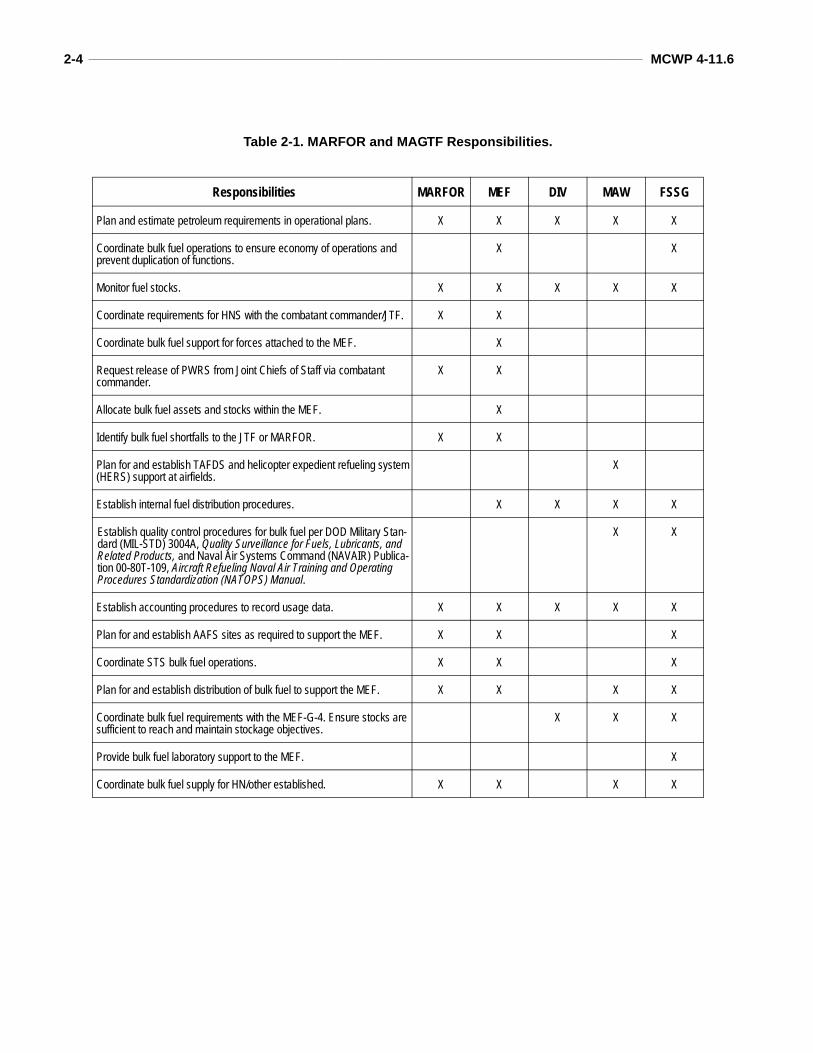
maintains liaison with the unified command JPO,NOLSC, and other military Services on mattersconcerning bulk fuel operations and policy. Seetable 2-1 (on page 2-4) for MARFOR and Marineair-ground task force (MAGTF) responsibilities.
Marine Corps Component Commander/MEFThe Marine Corps component commander isresponsible for wholesale logistic support at theService, theater, combatant commander, and HNlevel. The MEF is responsible for operational andtactical bulk fuel receipt, storage, and distribution.Accordingly, the MEF will work all retail logisticsprovisioning for the major subordinate com-mands. To this end, the MEF command element(CE) is responsible for requirements determina-tion and operations in and forward of the rear com-bat zone; the Marine component commander isresponsible for the COMMZ and supported/sup-porting combatant commander coordination. Allfuel operations in the MEF zone of action oramphibious objective area (AOA) will be coordi-nated by the MEF bulk petroleum officer. Linkageto the in-theater combatant commander JPO,DESC, HN, and other Service components is aMarine component commander responsibility.
Marine Aircraft WingThe Marine aircraft wing (MAW) G-4 is respon-sible for bulk fuel planning and coordination.Within the MAW, fuel support is providedthrough the Mar ine wing suppor t g roup(MWSG). The MWSG is comprised of bothfixed-wing (FW) and rotary-wing (RW) Marinewing support squadrons (MWSSs). Bulk fueloperations in support of the MAW are per-formed by the fuel branch within the MWSS.These units provide refueling support for MAWaircraft and ground equipment. The MWSS fuelbranch is responsible for the receipt, storage,distribution, and quality surveillance of bulkfuel in support of MAW operations. The fuelbranch of an MWSS is capable of providingrefueling support at two separate airfields simul-taneously. The difference between the RW and
2-4 ____________________________________________________________________________________________________ MCWP 4-11.6
Table 2-1. MARFOR and MAGTF Responsibilities.
Responsibilities MARFOR MEF DIV MAW FSSG
Plan and estimate petroleum requirements in operational plans. X X X X X
Coordinate bulk fuel operations to ensure economy of operations and prevent duplication of functions.
X X
Monitor fuel stocks. X X X X X
Coordinate requirements for HNS with the combatant commander/JTF. X X
Coordinate bulk fuel support for forces attached to the MEF. X
Request release of PWRS from Joint Chiefs of Staff via combatant commander.
X X
Allocate bulk fuel assets and stocks within the MEF. X
Identify bulk fuel shortfalls to the JTF or MARFOR. X X
Plan for and establish TAFDS and helicopter expedient refueling system (HERS) support at airfields.
X
Establish internal fuel distribution procedures. X X X X
Establish quality control procedures for bulk fuel per DOD Military Stan-dard (MIL-STD) 3004A, Quality Surveillance for Fuels, Lubricants, and Related Products, and Naval Air Systems Command (NAVAIR) Publica-tion 00-80T-109, Aircraft Refueling Naval Air Training and Operating Procedures Standardization (NATOPS) Manual.
X X
Establish accounting procedures to record usage data. X X X X X
Plan for and establish AAFS sites as required to support the MEF. X X X
Coordinate STS bulk fuel operations. X X X
Plan for and establish distribution of bulk fuel to support the MEF. X X X X
Coordinate bulk fuel requirements with the MEF-G-4. Ensure stocks are sufficient to reach and maintain stockage objectives.
X X X
Provide bulk fuel laboratory support to the MEF. X
Coordinate bulk fuel supply for HN/other established. X X X X
Petroleum and Water Logistics Operations ___________________________________________________________________ 2-5
FW fuel branches is the table of equipment. (Forcurrent quantities, refer to the Logistic Manage-ment Information System.)
Marine DivisionThe Marine division (MARDIV) is a fuel user,not a fuel provider. However, the MARDIV haslimited organic bulk fuel assets to support itsown units.
Force Service Support GroupThe force service support group (FSSG) providesbulk fuel supply support for the sustainment of theMEF. It provides all bulk fuel support that isbeyond the organic capabilities of supported units.Bulk fuel planning and coordination is performedin the FSSG G-3. To conduct bulk fuel operations,
the FSSG uses bulk fuel assets located within theengineer and motor transport organizations.
Engineer Support Battalion. The engineer sup-port battalion (ESB) is responsible for providinggeneral bulk fuel support to the MEF to includereceipt, storage, distribution, and quality surveil-lance. The ESB has one bulk fuel company toprovide this support. When supporting MAGTFairfields, the ESB is responsible for fuel distribu-tion to the airfield. The bulk fuel company of theESB provides coordination and control with theMAW for transfer of bulk fuel to the airfields.
Transportation Support Battalion. The generalsupport (GS) company and DS company in thetransportation support battalion provide the trans-portation and distribution of bulk fuel for the MEF.
CHAPTER 3. TACTICAL FUEL SYSTEMS
Marine Corps bulk fuel equipment has to meeta wide spectrum of requirements from STSoperations to aircraft refueling. To meet theserequirements, the Marine Corps has developed afamily of tactical fuel systems (TFSs). Each sys-tem is designed and configured specifically tosupport a unique mission requirement using sim-ilar components. The ability to alter fundamen-tal system configurations and interchangeabilityof components allows the creation of limitlesscombinations of tailored systems to meet mis-sion requirements.
The Marine Corps family of TFSs was originallydesigned and deployed in the 1950s to replace the55-gallon drum and 5-gallon fuel can as the pri-mary method for MARFOR’s bulk fuel support.The basic design of collapsible fuel tanks, trailer-mounted pumps, fuel hoses and valves, filtrationvessels, and miscellaneous components has pro-vided a solid foundation for the evolution of thefamily of TFSs to meet the ever changing opera-tional and tactical fuel support requirements ofthe MAGTF. Today the family of TFSs providesa wide range of storage tank sizes ranging from500-gallon to 50,000-gallon capacities withreceipt and pumping rates ranging from 125 gal-lons per minute (GPM) to 600 GPM.
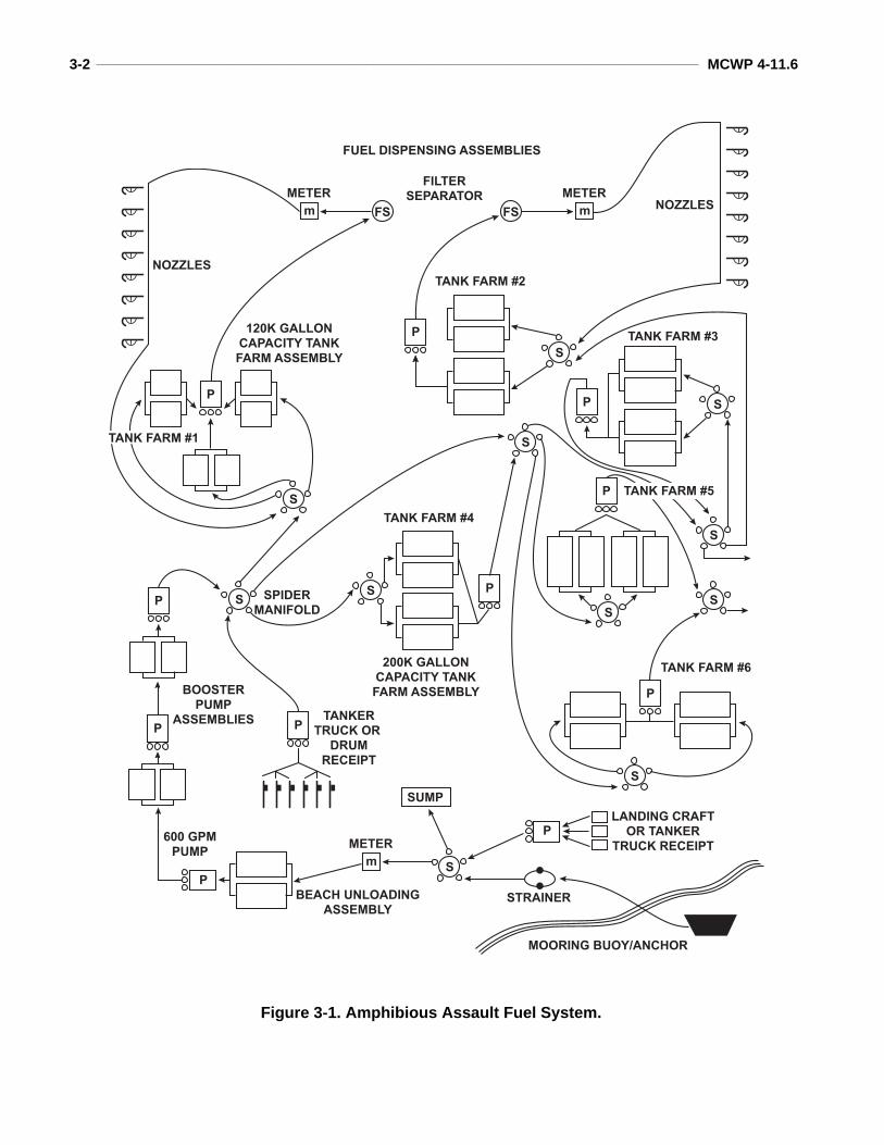
Amphibious Assault Fuel System
The AAFS (USMC table of authorized materielcontrol number [TAMCN] B0685) is the largestTFS. Consisting of many assemblies, the AAFSis used to receive, store, transfer, and dispense alltypes of fuel. The AAFS supplies bulk fuel to allelements of a MAGTF including distribution byhose line to airfields. The system can receive fuel
from offshore vessels, railcars, tank trucks, bulkstorage tanks, pipeline/hose line, and drums. Fuelis stored and can be transferred to another stor-age site or dispensed to individual containers,vehicles, tank trucks, and other fuel systems. Sixassemblies compose the AAFS:
Beach unloading. Receiving.Two booster stations. Two adapting.Two dispensing.Six tank farms.
Each AAFS has one beach unloading assemblyused for receiving fuel during STS operations.Two booster station assemblies in each AAFS areused when the distance between storage sites isgreater than the pumping distance. The AAFSstorage capacity comes from the six tank farms.One receiving assembly in each AAFS providesthe capability to receive fuel from multiplesources. Two dispensing assemblies in eachAAFS provide the capability to dispense fuel.The AAFS has two adapting assemblies to makethe system compatible with commercial and otherServices’ fuel systems. Versatility is an impor-tant part of the AAFS, which can be deployed asa whole or tailored to meet mission requirements.
The AAFS storage capacity is 1.12 million gal-lons made up from its six tank farms. The AAFShas approximately 5 miles of 6-inch assault hoseand uses 600-GPM pumping capabilities. Usingquick-connect, cam-lock fittings, the AAFS canbe assembled without tools and is compatible withthe other Marine Corps TFSs. See figure 3-1 onpage 3-2.
3-2 ____________________________________________________________________________________________________ MCWP 4-11.6
P
P
P
S
S
S
SS
S
S
S
S
P
S
P S
P
P
P
P
P
SUMP
m
METER
FSFS m
METER
m
METERFILTER
SEPARATOR
NOZZLES
NOZZLES
120K GALLON
CAPACITY TANK
FARM ASSEMBLY
200K GALLON
CAPACITY TANK
FARM ASSEMBLY
TANK FARM #2
TANK FARM #3
TANK FARM #4
SPIDER
MANIFOLD
BOOSTER
PUMP
ASSEMBLIES
600 GPM
PUMP
PTANKER
TRUCK OR
DRUM
RECEIPT
BEACH UNLOADING
ASSEMBLY
LANDING CRAFT
OR TANKER
TRUCK RECEIPT
STRAINER
MOORING BUOY/ANCHOR
TANK FARM #6
TANK FARM #1
TANK FARM #5
FUEL DISPENSING ASSEMBLIES
Figure 3-1. Amphibious Assault Fuel System.
Petroleum and Water Logistics Operations ___________________________________________________________________ 3-3
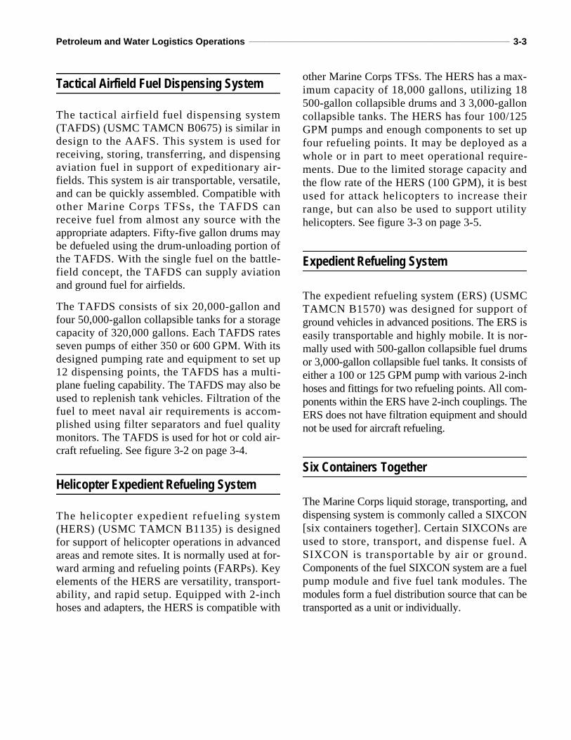
Tactical Airfield Fuel Dispensing System
The tactical airfield fuel dispensing system(TAFDS) (USMC TAMCN B0675) is similar indesign to the AAFS. This system is used forreceiving, storing, transferring, and dispensingaviation fuel in support of expeditionary air-fields. This system is air transportable, versatile,and can be quickly assembled. Compatible withother Marine Corps TFSs, the TAFDS canreceive fuel from almost any source with theappropriate adapters. Fifty-five gallon drums maybe defueled using the drum-unloading portion ofthe TAFDS. With the single fuel on the battle-field concept, the TAFDS can supply aviationand ground fuel for airfields.
The TAFDS consists of six 20,000-gallon andfour 50,000-gallon collapsible tanks for a storagecapacity of 320,000 gallons. Each TAFDS ratesseven pumps of either 350 or 600 GPM. With itsdesigned pumping rate and equipment to set up12 dispensing points, the TAFDS has a multi-plane fueling capability. The TAFDS may also beused to replenish tank vehicles. Filtration of thefuel to meet naval air requirements is accom-plished using filter separators and fuel qualitymonitors. The TAFDS is used for hot or cold air-craft refueling. See figure 3-2 on page 3-4.
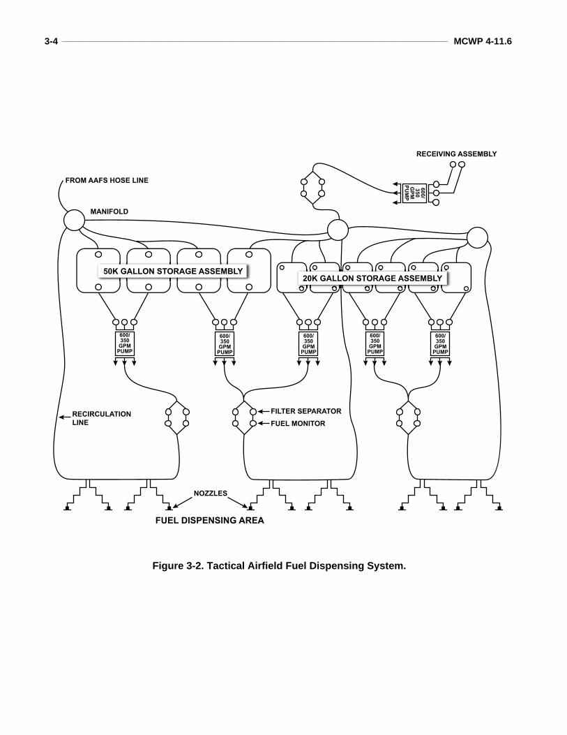
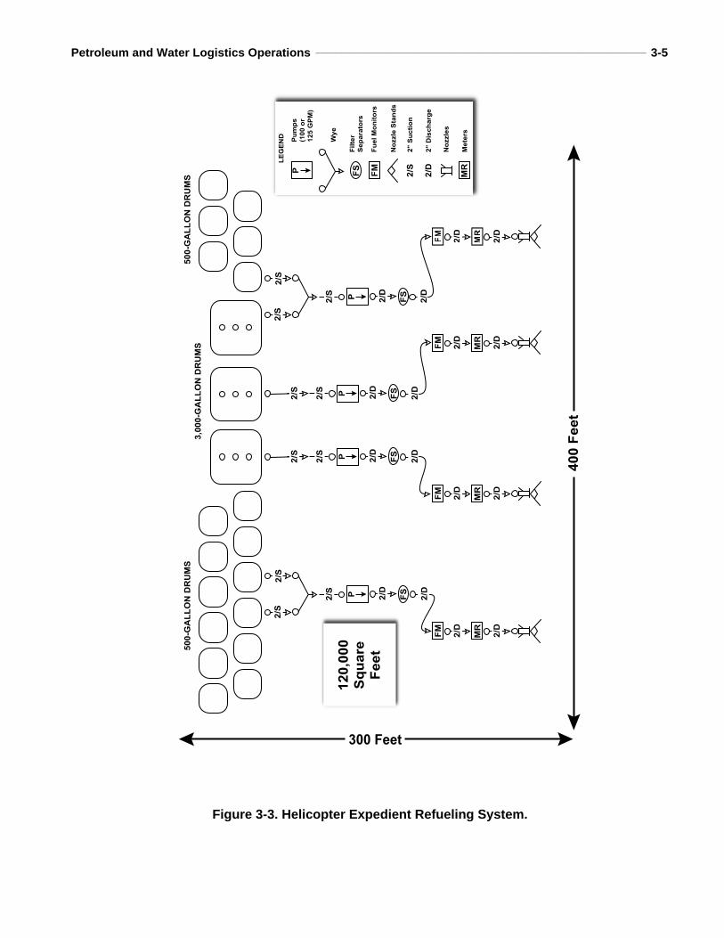
Helicopter Expedient Refueling System
The helicopter expedient refueling system(HERS) (USMC TAMCN B1135) is designedfor support of helicopter operations in advancedareas and remote sites. It is normally used at for-ward arming and refueling points (FARPs). Keyelements of the HERS are versatility, transport-ability, and rapid setup. Equipped with 2-inchhoses and adapters, the HERS is compatible with
other Marine Corps TFSs. The HERS has a max-imum capacity of 18,000 gallons, utilizing 18500-gallon collapsible drums and 3 3,000-galloncollapsible tanks. The HERS has four 100/125GPM pumps and enough components to set upfour refueling points. It may be deployed as awhole or in part to meet operational require-ments. Due to the limited storage capacity andthe flow rate of the HERS (100 GPM), it is bestused for attack helicopters to increase theirrange, but can also be used to support utilityhelicopters. See figure 3-3 on page 3-5.
Expedient Refueling System
The expedient refueling system (ERS) (USMCTAMCN B1570) was designed for support ofground vehicles in advanced positions. The ERS iseasily transportable and highly mobile. It is nor-mally used with 500-gallon collapsible fuel drumsor 3,000-gallon collapsible fuel tanks. It consists ofeither a 100 or 125 GPM pump with various 2-inchhoses and fittings for two refueling points. All com-ponents within the ERS have 2-inch couplings. TheERS does not have filtration equipment and shouldnot be used for aircraft refueling.
Six Containers Together
The Marine Corps liquid storage, transporting, anddispensing system is commonly called a SIXCON[six containers together]. Certain SIXCONs areused to store, transport, and dispense fuel. ASIXCON is transportable by air or ground.Components of the fuel SIXCON system are a fuelpump module and five fuel tank modules. Themodules form a fuel distribution source that can betransported as a unit or individually.
3-4 ____________________________________________________________________________________________________ MCWP 4-11.6
RECEIVING ASSEMBLY
MANIFOLD
RECIRCULATION
LINE
FILTER SEPARATOR
FUEL MONITOR
NOZZLES
FROM AAFS HOSE LINE
20K GALLON STORAGE ASSEMBLY50K GALLON STORAGE ASSEMBLY
FUEL DISPENSING AREA
600/350GPMPUMP
600/350GPMPUMP
600/350GPMPUMP
600/350GPMPUMP
600/350GPMPUMP
600/
350
GPM
PUMP
Figure 3-2. Tactical Airfield Fuel Dispensing System.
Petroleum and Water Logistics Operations ___________________________________________________________________ 3-5
500-GALLONDRUMS
3,000-GALLONDRUMS
500-GALLONDRUMS
FM
MR
2/D
2/D
FM
MR
2/D
2/D
FM
MR
2/D
2/D
FM
MR
2/D
2/D
2/S P FS
2/S
2/D
2/D
P FS
2/S
2/S
2/S
2/D
2/D
2/S P FS
2/S
2/D
2/D
P FS
2/S
2/S
2/S
2/D
2/D
P
MR
2/S
2/D
LEGEND
FM
FS
Pumps
(100or
125GPM)
Wye
Filter
Separators
FuelMonitors
NozzleStands
2"Suction
2"Discharge
Nozzles
Meters
120,000
Square
Feet
300 Feet
400Feet
Figure 3-3. Helicopter Expedient Refueling System.
3-6 ____________________________________________________________________________________________________ MCWP 4-11.6
Fuel Pump Module
The SIXCON fuel pump module (USMCTAMCN B1580) consists of a 125-GPM pump,100-GPM filter separator, 100-GPM fuel qual-ity monitor, meter assembly, and hose reel. Thefuel pump was designed to dispense fuel fromseveral types of fuel tanks, for either defuelingor for filtering aircraft or ground fuels. The rateof transfer for the SIXCON pump module is upto 100 GPM.
Fuel Tank Modules
Each SIXCON fuel tank module (USMCTAMCN B2085) is made of stainless steel andhas a capacity of 900 gallons. It is encased by asteel frame that allows stacking and connecting toform an 8- by 8- by 20-foot International Organi-zation for Standardization (ISO) container. Thefuel tank is equipped with all the hoses and adapt-ers to connect the tanks to the pump unit.
Accessories SIXCON modules are interconnected using spe-cial horizontal and vertical ISO connectors.Fuel is transferred via 2-inch hoses with dry-break couplings. This allows rapid assemblyand disassembly without loss of fuel or damageto the environment.
Cyclic Resupply SIXCON modules are assigned to all elements ofthe MAGTF. These organizations may implementa cyclic resupply procedure where full modulesare exchanged for empty ones. SIXCONs mayalso be assigned to using organizations for mini-mal fuel handling at the operator level.
M970 Mobile Refueler
The M970 5,000-gallon mobile refueler (USMCTAMCN D0215) provides aircraft refueling/defu-eling and over-the-road transportation of bulk
fuel. It is assigned to both the aviation combatelement (ACE) and the combat service supportelement (CSSE). Within the ACE, the M970 isorganic to the MWSS and is used primarily torefuel aircraft. Within the CSSE, the M970 isorganic to the transportation support battalion andis assigned to CSSE motor transport and/or engi-neer detachments. The CSSE uses the M970 totransport bulk fuel between storage sites ordirectly to the customer.
Tactical Petroleum Laboratory, Medium
The tactical petroleum laboratory, medium(TPLM) (USMC TAMCN B0695) provides theessential testing components integrated into anISO container to monitor the critical physical andchemical characteristics of aviation and groundfuels. There are 16 tests that can be conducted inaccordance with the American Society for Testingand Materials (ASTM). JP-4, JP-5, JP-8, diesel,and their commercial grade equivalents can betested for composition and quality against mini-mum standards as specified in DOD MIL-STD3004A. The TPLM can also test captured fuels.
USMC Aircraft Bulk Fuel Handling Systems
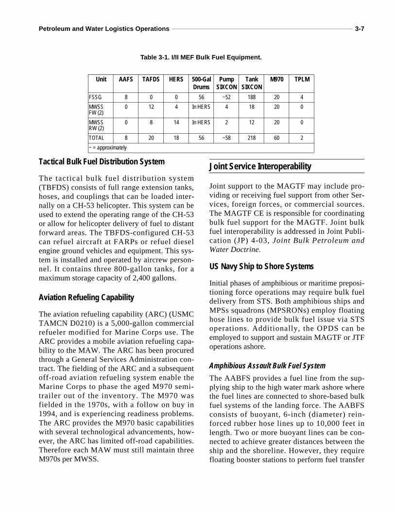
Air-to-air refueling or transfer of bulk aviationfuel can both extend the range of aircraft and pro-vide a means for the MAGTF to “air deliver” jetfuel to forward operating sites. (NOTE: Jet fuelcan also be used as diesel fuel.) Table 3-1 is alisting of I/II MEF bulk fuel equipment.
USMC KC-130R Transport
The primary mission of the KC-130R Transportis air-to-air refueling. It can air-to-air refuel tacti-cal Marine FW aircraft, CH-53 helicopters, andMV-22s. The KC-130R can also land at distantairfields carrying up to 10,000 gallons of jet fuel.
Petroleum and Water Logistics Operations ___________________________________________________________________ 3-7
Tactical Bulk Fuel Distribution System
The tactical bulk fuel distribution system(TBFDS) consists of full range extension tanks,hoses, and couplings that can be loaded inter-nally on a CH-53 helicopter. This system can beused to extend the operating range of the CH-53or allow for helicopter delivery of fuel to distantforward areas. The TBFDS-configured CH-53can refuel aircraft at FARPs or refuel dieselengine ground vehicles and equipment. This sys-tem is installed and operated by aircrew person-nel. It contains three 800-gallon tanks, for amaximum storage capacity of 2,400 gallons.
Aviation Refueling Capability
The aviation refueling capability (ARC) (USMCTAMCN D0210) is a 5,000-gallon commercialrefueler modified for Marine Corps use. TheARC provides a mobile aviation refueling capa-bility to the MAW. The ARC has been procuredthrough a General Services Administration con-tract. The fielding of the ARC and a subsequentoff-road aviation refueling system enable theMarine Corps to phase the aged M970 semi-trailer out of the inventory. The M970 wasfielded in the 1970s, with a follow on buy in1994, and is experiencing readiness problems.The ARC provides the M970 basic capabilitieswith several technological advancements, how-ever, the ARC has limited off-road capabilities.Therefore each MAW must still maintain threeM970s per MWSS.
Joint Service Interoperability
Joint support to the MAGTF may include pro-viding or receiving fuel support from other Ser-vices, foreign forces, or commercial sources.The MAGTF CE is responsible for coordinatingbulk fuel support for the MAGTF. Joint bulkfuel interoperability is addressed in Joint Publi-cation (JP) 4-03, Joint Bulk Petroleum andWater Doctrine.
US Navy Ship to Shore Systems
Initial phases of amphibious or maritime preposi-tioning force operations may require bulk fueldelivery from STS. Both amphibious ships andMPSs squadrons (MPSRONs) employ floatinghose lines to provide bulk fuel issue via STSoperations. Additionally, the OPDS can beemployed to support and sustain MAGTF or JTFoperations ashore.
Amphibious Assault Bulk Fuel SystemThe AABFS provides a fuel line from the sup-plying ship to the high water mark ashore wherethe fuel lines are connected to shore-based bulkfuel systems of the landing force. The AABFSconsists of buoyant, 6-inch (diameter) rein-forced rubber hose lines up to 10,000 feet inlength. Two or more buoyant lines can be con-nected to achieve greater distances between theship and the shoreline. However, they requirefloating booster stations to perform fuel transfer
Table 3-1. I/II MEF Bulk Fuel Equipment.
Unit AAFS TAFDS HERS 500-Gal Drums
PumpSIXCON
TankSIXCON
M970 TPLM
FSSG 8 0 0 56 ~52 188 20 4MWSSFW (2)
0 12 4 In HERS 4 18 20 0
MWSSRW (2)
0 8 14 In HERS 2 12 20 0
TOTAL 8 20 18 56 ~58 218 60 2~ = approximately
3-8 ____________________________________________________________________________________________________ MCWP 4-11.6
when the distance is more than 5,000 feet.Buoyant hose systems are employed to supportthe initial phases of amphibious landings. AnAABFS can be installed in 4 to 6 hours underfavorable surf conditions.
Offshore Petroleum Discharge SystemThe OPDS is designed to discharge petroleumproducts to USMC AAFS, US Army tacticalpetroleum terminals, or US Army IPDS pipe-lines. The OPDS can be installed up to 4 statutemiles offshore and support STS fuel replenish-ment rates of up to 1.2 million gallons per day(based on a 20-hour operating day). If the shipstandoff distance is less than 2 statute miles,dual lines can be used resulting in faster prod-uct transfer.
The OPDS can produce delivery rates of 1,000GPM. The OPDS includes the initial fuel tanker(ship) that provides the initial delivery of fuel (upto 15 million gallons) and the mooring apparatusfor itself and follow-on tankers. The OPDSemploys either a four-point moor or a singleanchor leg mooring with surface buoy to allowthe ship to moor and “weather vane” in the pre-vailing winds in a 360-degree arc.
Military Sealift Command civilian crews installthe system with the assistance of naval supportpersonnel. Besides underwater divers and supportpersonnel from an amphibious construction battal-ion, the system requires side-loadable warping tugs
and/or powered or non-powered causeway sectionsto conduct the installation.
US Army Petroleum System
Theater support may be provided from US Armyfuel sources. Fuel support, which includes inter-face with Marine Corps TFSs, must be plannedand coordinated in advance. The selection of spe-cific systems depends on the projected require-ments. The US Army theater fuel managercoordinates fuel delivery requirements. Whenoperating with the US Air Force, the US Armycan airdrop fuel in quantities up to 10,000 gallonsin support of operating forces. Fuel support equip-ment employed may include US Army tacticalpetroleum terminals, IPDS or line haul vehicles.
US Air Force Air-based Petroleum System
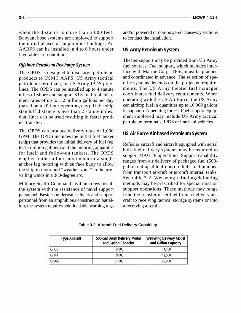
Refueler aircraft and aircraft equipped with aerialbulk fuel delivery systems may be required tosupport MAGTF operations. Support capabilityranges from air delivery of packaged fuel (500-gallon collapsible drums) to bulk fuel pumpedfrom transport aircraft or aircraft internal tanks.See table 3-2. Wet-wing refueling/defuelingmethods may be prescribed for special missionsupport operations. These methods may rangefrom the transfer of jet fuel from a delivery air-craft to receiving tactical storage systems or intoa receiving aircraft.
Table 3-2. Aircraft Fuel Delivery Capability.
Type Aircraft 500-Gal Drum Delivery Modeland Gallon Capacity
Wet-Wing Delivery Model and Gallon Capacity
C-130 5,000 4,400C-141 9,000 12,500C-5A/B 27,000 29,000
CHAPTER 4. BULK FUEL PLANNING
Normally, bulk fuel capabilities are spreadthroughout the MAGTF. This is especially trueof bulk fuel distribution capabilities. But withthe smaller forces of today, there is often a bene-fit to consolidating the bulk fuel assets. Forexample, if a mobile refueler was controlled by acentral organization, it could be used to supportseveral units and would be used to the maxi-mum extent possible. This would not be true ifeach unit had its own mobile refueler. TheMAGTF has also provided central organizationswithin the ACE and the CSSE for its bulk liquidsstorage requirements.
To be effective, the overall bulk fuel effort needsto be planned and coordinated at the MAGTFlevel as early as possible and continue through-out the operation.
Planning Requirements
Planning for bulk fuel support can be a complexand challenging task. Time, space, distances, ter-rain, resources, and the operating environment areall planning factors that have to be considered.There are six major elements of bulk fuel planning:requirements, sourcing and procurement, transpor-tation, storage, distribution, and equipment.
Requirements
Determining bulk fuel requirements is one of themost important planning elements for bulk fuelsupport. Requirements have to be determinedbefore any of the other elements can be effec-tively considered. Requirements will be the mainfactor in deciding equipment, personnel, andstockage objectives.
Sourcing and Procurement
Determining the source and provider of bulk fuelstocks to the MAGTF or MARFOR varies greatlydepending on the situation. Before deploying, theplanner needs to coordinate fuel sources andestablish resupply procedures.
Transportation
Planning for bulk fuel transportation involvesmovement of fuel from the fuel source to theMarine Corps bulk fuel sites. This is usually awholesale function that will be arranged in coor-dination with the JPO, MAGTF fuels officer, andthe theater area support command. Transporta-tion methods include ships, railcars, tank trucks,pipeline, and aircraft.
Storage
Planning for bulk fuel storage requires a consid-eration of requirements, stockage objectives, andthe frequency of resupply. The JFC prescribesbulk fuel supply levels for the theater in day(s) ofsupply (DOS). Marine component and/orMAGTF commanders prescribe supply levels forMarine forces based on requirements and equip-ment availability. When operating in a joint envi-ronment, the Marine Corps planners must planfor the supply levels of all organizations that itmay be supporting.
Distribution
Distribution consists of transporting fuel from thebulk storage site to the using units. Distributioncan also be called the retail end of the transporta-tion system.
4-2 ____________________________________________________________________________________________________ MCWP 4-11.6
Equipment
The bulk fuel equipment required to support themission is based on the other five elements forbulk fuel planning. Planning for bulk fuel equip-ment must include both stationary and mobilebulk fuel equipment.
Planning Considerations
The bulk fuel supply system must be designedaccording the mission, terrain, and climate. Theplanner must consider the following:
Capability of installations and/or unit (to includeHN) to provide the required support.Time to construct an operational bulk fuelsystem.Requirements for bulk fuel storage facilities,offshore unloading facilities, pipeline/hoseline, and distribution points.Availability of bulk fuel units and other unitsneeded to construct, install, operate, and main-tain the bulk fuel system.Terrain, since this impacts both the ability toinstall the bulk fuel system and fuel usagefactors.
Planning for Joint Bulk Fuel Operations
The supported combatant commander and/or theJFC are responsible for the overall planning ofbulk fuel logistical support. The unified or jointcommand plan is the basis for all subordinatebulk fuel support plans. This plan establishesconcepts, objectives, and missions, and allocatesavailable resources. Operation plans submitted tothe joint staff will include a Petroleum, Oils, andLubricants Appendix to the Logistics Annex inthe format prescribed in Chairman of the JointChiefs of Staff Manual 3122.03A, Joint Opera-tion Planning and Execution System (JOPES),
Volume II, Planning Formats and Guidance. Seeappendix A. Once the concept is approved by theJFC, the Service components then prepare theimplementing bulk fuel support plan. Duringoperations, the joint staff and the Service bulkfuel planners revise the basic plans as required tosupport the mission.
Army Petroleum Group
Normally, the Army petroleum group or desig-nated dominant Service is responsible for theaterbulk fuel planning and the theater inland petro-leum distribution plan. This planning is done inconcert with the component Services’ bulk fuelplans. The theater inland petroleum distributionplan is prepared and published as an annex to thetheater logistic support plan.
Compatibility
During joint operations, the compatibilitybetween the Services’ bulk fuel systems is a keyfactor. Compatibility must be addressed duringthe planning cycle with emphasis on the follow-ing interfaces:
STS offload facilities. Land-based distribution systems and mobilerefueling equipment.
Marine Corps Bulk Fuel Planning
The Marine Corps must maintain the ability todeploy rapidly to a variety of environments andtactical situations. Once in place, Marine Corpsforces must be able to operate with a full spec-trum of bulk fuel support. A key factor to suc-cessful bulk fuel planning is early coordinationbetween the fuel planners and the operators. Todevelop an effective fuel plan, the planners musthave a good understanding of the commander’sconcept of operations and the tactical equipmentbeing used.
Petroleum and Water Logistics Operations ___________________________________________________________________ 4-3
Determine Requirements
The first step is to collect fuel requirement datafrom each element of the MAGTF so the plannercan estimate the fuel requirements for Marineforces. While this is not intended to be an exactfigure, it does need to be as accurate as possiblebecause of the large impact fuel requirementshave on other planning elements.
Automated SystemsData provided by automated systems must bevalidated by fuel planners using equipmentdensities and consumption rates.
Time PhasingAn equally important function of bulk fuelrequirements identification is time phasing. Bulkfuel requirements must be time phased to coordi-nate transportation, storage, and distribution.Time-phased requirements begin with a determi-nation of daily requirements in the objective area.This includes daily demand, storage capacity,throughput capability, and time delay from initialrequest until delivery.
Methods of Computing Fuel RequirementsAll MAGTF elements are responsible for estimat-ing their fuel requirements and submitting them tothe fuel planners in a timely manner. Fuel require-ments should be computed at the staff level basedon historical data, equipment density, time, andoperational tempo. Fuel planners need to providespecific guidance to the units on the procedures tobe followed. The guidance should provide data
concerning hours-per-day, gallons per hour (GPH),resupply times, DOS on hand, and operationaltempo. The bulk fuel staff officers will reviewrequirements submissions for accuracy.
Most units in the fuel community have devel-oped automated tools such as spreadsheets toassist in the fuel planning. These tools should beavailable from the MEF bulk liquids sections orthe Marine Corps Detachment, Fort Lee, VA.
Aviation fuel requirements are computed usingaircraft characteristic manuals. This methodtakes into account the operational tempo, sortierates, sortie lengths, and fuel rates for each typeof aircraft. It is also recommended that aviationfuel requirements be computed at the staff levelbased on the aircraft density and the operationaltempo provided from the G-3/S-3. The bulk fuelstaff officers will review requirements submis-sions for accuracy.
Notional MAGTF Bulk Fuel Requirements
Notional fuel requirements are often used duringplanning, especially before an equipment list hasbeen generated or compiled. Notional fuelrequirements are based on established fuel con-sumption rates and hours per day for equipmentin participating units.
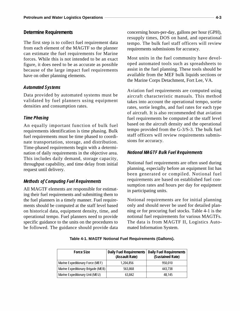
Notional requirements are for initial planningonly and should never be used for detailed plan-ning or for procuring fuel stocks. Table 4-1 is thenotional fuel requirements for various MAGTFs.The data is from MAGTF II, Logistics Auto-mated Information System.
Table 4-1. MAGTF Notional Fuel Requirements (Gallons).
Force Size Daily Fuel Requirements(Assault Rate)
Daily Fuel Requirements(Sustained Rate)
Marine Expeditionary Force (MEF) 1,204,856 950,010Marine Expeditionary Brigade (MEB) 563,868 443,738Marine Expeditionary Unit (MEU) 63,842 48,145
4-4 ____________________________________________________________________________________________________ MCWP 4-11.6
Sourcing and Procurement
Marine planners must be aware of the variousagencies and procedures for procuring bulk fuel.The sources of bulk fuel procurement are as var-ied as the possible missions and objectives thatcould be assigned a MAGTF. After analyzingfuel requirements, the Marine planner turns to thetheater petroleum manager or joint staff to coor-dinate fuel sourcing and transportation.
Transportation
Transportation planning may include commer-cial contracted hauling, railway tankers, ship-p ing , o the r Se rv i ce a s se t s and p ipe l ineavailability. MAGTF planners should look at allavailable transportation assets in the area andplan for adequate tactical transportation assets tobe deployed in a timely manner. These transpor-tation assets are also key elements in determin-ing the fuel support equipment and personnelrequired. If the fuel source is close and transpor-tation is readily available, the planner may nothave to provide as much storage capacity. If theLOCs are long and resupply is not timely, theplanner may have to increase the stockage objec-tive, which means storage equipment will have tobe increased.
Transportation often represents the greatest chal-lenge to the logistical field due to the highdemand for transportation assets.
Storage
The fuel planner must consider storage and distri-bution assets required and personnel to operate andmaintain them. Storage requirements are based onthe anticipated usage by a supported unit and thestockage objective as established by the com-mander. Stock levels to be stored will depend onconsumption rates, resupply methods, transporta-tion assets, and distribution systems. Storage meth-ods, land requirements, and security are the keyfactors in storage planning. It is important that thebulk fuel storage equipment be scheduled for
delivery to the operating area in order to allow forinstallation of the storage systems in time to sup-port the transportation schedule.
Distribution
Distribution is often the most difficult of the bulkfuel missions. Equipment, time-phased require-ments, and distance are the main factors affect-ing distribution. Distribution problems willnormally become more complex the longer theoperation, the greater the consumption rates, andthe farther inland the MAGTF goes. Resupplyconcepts of unit distribution versus supply pointdistribution will also affect the type and amountof resources needed to support bulk fuel distribu-tion to the MAGTF.
War Reserve Requirements and Stocks
Petroleum War Reserve Requirement
To ensure the supply of petroleum products in theinitial phases of a contingency, the unified com-mands and the Services develop requirements tosize petroleum war reserve stocks properly. Thepetroleum war reserve requirement (PWRR) isbased on the need to support specific contin-gency operations until normal LOCs are estab-lished and resupply arrangements are in place.The joint staff develops guidelines, approved bythe Office of the Secretary of Defense, on DOSand appropriate assumptions on secure sources ofresupply. These guidelines are provided to theServices and combatant commanders and serve asthe basis for determining requirements. Usingthese guidelines, the Services develop and applystructured, auditable methods of computingPWRR for each approved theater/command oper-ation plan (OPLAN).
Petroleum War Reserve Stocks PWRS are the on-hand product designated to sat-isfy PWRR. This stockage is in addition to thepeacetime operating stock for each location.
Petroleum and Water Logistics Operations ___________________________________________________________________ 4-5
Commanders of unified commands are autho-rized to release or reallocate PWRS in emer-gency situations. PWRS are usually stored intheater and are monitored by the appropriatecombatant commander JPO/SAPO.
MEF Petroleum War Reserve Requirement
The MEF computes PWRR based on the timeperiod, contingency location, and type of productrequired. The joint staff also establishes preposi-tioning objectives for regions and areas world-wide in the form of combat days of petroleumsupply to be maintained in accordance withDODD 4140.25. These objectives consider suchfactors as wartime tanker sailing times, in theaterdistribution times, attrition factors, and appropri-ate safety levels. As a result, the amount of bulkfuel PWRR (DOS) that the MEF can register var-ies depending on the theater in which the MEF isoperating. The MEF will usually have less than60 DOS of bulk fuel as accompanying supplies orPWRS, and resupply will begin at a date earlierthan D+60.
Consolidated Defense Fuel Support PointsThe DESC consolidates military Service PWRRfor storage at defense fuel support points andassigns maximum and minimum storage levelsin the inventory management plan (IMP). In
consonance with approved stock fund operatingplans and budgets, it is possible that the entireamount of PWRS that the MEF is authorized ina particular theater may not be sourced. If theMARFOR have a bulk fuel shortfall, the Marinecomponent commander will notify the appropri-ate unified commander’s JPO. The documentthat identifies the amount of PWRS allocated tothe MEF is the DESC IMP. The IMP containsthe MEF PWRR by location and identifies thePWRS that are sourced to meet that require-ment. The Marine component G-4 and MEFbulk liquids section maintain current copies ofthe IMP, and it is also available via the classi-fied SECRET Internet Protocol Router Network(SIPRNET).
Prepositioned PWRS
DESC will attempt to preposition PWRS at theterminal location nominated by the military Ser-vice. Where storage or operational conditions arelimited, DESC will locate stocks, at the mostappropriate alternate terminal, following coordi-nation with the unified command and the requir-ing military Service. Malpositioned stocks will becounted against the total PWRR. However, thesestocks may not be counted as DOS available atthe point of planned use during assessment ofOPLANs capability.
CHAPTER 5. BULK FUEL THEATER OPERATIONS
In theater operations, the MAGTF commandermay be part of a developed or undeveloped the-ater. Bulk fuel support concerns and requirementsare addressed according to the development stageof a theater. The three main objectives of bulkfuel support are supplying fuel when needed, dis-tributing fuel where needed, and providing fuelresupply on time. When the MAGTF is involvedin a sustained operation ashore, bulk fuel opera-tions are deployed in three phases: development,lodgment, and build-up.
Developed Theater
In a developed theater, an existing bulk fuel distri-bution system is usually available to help supportMARFOR. The existing system helps offset therequirements for Marine Corps TFSs. A developedtheater usually consists of tanker unloading facili-ties, terminals, pipelines, pump stations, dispensingfacilities, and rail tank car facilities.
Actual procedures for accomplishing the deliv-ery of bulk fuel to the user will vary between the-aters. Civilian personnel or the theater Army willnormally operate these facilities. However,Marine Corps bulk fuel units could be taskedwith operating the facilities, particularly duringthe early phases of operations before the theaterArmy has all its assigned forces.
Pipeline System
In a developed theater, the pipeline system usu-ally extends into the Army corps rear with hoseline extensions into Army corps storage sites andMarine Corps force combat service support(CSS) areas and airfields. When practical, branchlines from the pipeline are used to supply majorusers such as Marine Corps CSSDs and MWSSs.
Military tank trucks and commercial vehicles, ifrequired and available, can supplement the pipe-line/hose line system.
Theater Stockage Objectives
In a developed theater, most of the theater stock-age objectives are usually held in fixed facilitystorage tanks. This reduces the quantity of bulkfuel that the Marine Corps would need to store intactical bulk fuel systems. Theater stockageobjectives will vary between theaters dependingon planned operational contingency anticipatedusage rates. Marine forces stockage objectivesheld in tactical fuel systems will depend onresupply times from theater storage and the dailyfuel requirement.
Undeveloped Theater
Providing fuel support in an undeveloped theaterpresents many problems not faced in a developedarea. TFSs have to be brought into the area andmooring facilities, storage facilities, pipeline,and/or hose lines have to be installed. During theearly stages of an operation, forces have to relyon their organic equipment and personnel. As theoperation progresses, additional equipment andpersonnel are brought in to expand the fuel sys-tem. A TFS capable of supporting the mission isdeveloped in the area when practical. Initial fuelstorage facilities should be expanded when possi-ble so floating storage (tankers or barges) hold-ing reserve fuel for shore units may be released.
Any available commercial or HNS will be consid-ered for use as part of the bulk fuel system. Use ofthese systems and their bulk fuel products shouldbe obtained through DESC contracts, local pur-chase procedures, or through HNS agreements.
5-2 ____________________________________________________________________________________________________ MCWP 4-11.6
Minimum Bulk Fuel Stockage Objective
The minimum bulk fuel stockage objective forthe undeveloped theater is 15 DOS. This includesbulk fuel stored in tactical equipment and off-shore shipping or floating dumps. Fuel is distrib-uted from beach storage by hose line, tankvehicles, helicopters, and any other means avail-able. As the fuel system is developed, it will con-sist of hose lines and collapsible storage tanks.The primary method of receiving bulk fuel in theundeveloped theater will be STS operations usingNavy shipping with the AABFS or the OPDS,tanker vehicles, barges, or any other suitabletransportation asset.
Tactical Hose Line
Large users such as tactical airfields are sup-plied by tactical hose line when possible. Thetactical hose line and/or pipeline will extend asfar forward as possible, usually into the Armycorps rear area, to reduce mobile transportrequirements. Although hose lines are the mostrapid and easily deployed system, a more per-manent system is normally installed if the sys-tem must stay in place for long periods. Whenpossible, the rear area COMMZ, corps support,and force service support areas will be estab-lished. In the early stages, the theater may onlyconsist of a JTF support area, MEF forward areawith CSSDs, or Army division support area, andlater an Army corps support area. The rear areaCOMMZ may never be formed depending onthe duration of the operation.
Air Lines of CommunicationsIn the early stages of an undeveloped theater, thereis often a requirement to support forces with air linesof communications (ALOC). The Air Force AMCprovides this support with C-130, C-141, C-5A, andC-17 aircraft. Requirements for ALOC support arecoordinated through channels established in theOPLANs. If the forces advance using air assets, thennormally the ALOC is required to support them. The
following types of aerial bulk fuel support are avail-able from the AMC.
Packaged Products
The 5-gallon fuel cans and 55-gallon drums maybe internally loaded in cargo aircraft for deliveryto airfields near the units being supported.
Airdrop
When suitable aircraft loading and unloadingareas are not available, fuel may be airdropped ordelivered by low-altitude parachute extractionsystems. A 500-gallon collapsible drum can betransported internally or externally to deliver fuel.
Aerial Bulk Fuel Delivery System
The Air Force and Marine Corps have aircraftspecially equipped with internal collapsible tanksand a pump for deliveries of bulk fuels into areaswhere suitable landing sites are available.
Wet Wing Refueling
The C-130, C-141, C-5A, and C-17 aircraft haveinternal pumps for defueling. Using Marine Corpsor Army ground equipment (hoses and nozzles),these aircraft can deliver aviation fuel into MarineCorps or Army storage containers located at suit-able landing areas. Refer to table 3-2, page 3-8.
Tactical Bulk Fuel Delivery SystemThis system is installed and operated by aircrewpersonnel. It contains three 800-gallon tanks, fora maximum storage capacity of 2,400 gallons. Itcan be used at forward sites to dispense fuel toother aircrafts or ground vehicles.
Phases of Bulk Fuel Operations
During sustained operations ashore (SOA), tacti-cal bulk fuel equipment must be deployed to pro-vide support to the MAGTF. To best support the
Petroleum and Water Logistics Operations ___________________________________________________________________ 5-3
MAGTF, bulk fuel operations should be con-ducted in three phases: development, lodgment,and build-up.
Development
Due to the high consumption and limited bulkfuel capabilities, the development phase is oftenthe most critical phase of bulk fuel operations.The commander and staff need to look closely atthe full range of the vehicles going ashore, thetime-phased resupply available, and the equip-ment available to support the MAGTF during thisphase. The development phase may be initiatedas an airborne, airmobile, amphibious assault, oran uncontested debarkation at a friendly port.
The first units of the MAGTF entering an opera-tional area will probably carry only enough bulkfuel for immediate purposes. Resupply of theseunits must begin rapidly. During initial deploy-ment, fuel will probably be provided in prepack-aged containers (drums and cans), 500-gallontanks, SIXCONs, and mobile refuelers, thendelivered to the AOA by surface or air from off-shore amphibious ships. These items must becontinually recovered and sent back to the sourceto be reused. All bulk fuel resources within theAOA must be considered and exploited duringthis phase.
Lodgment
The lodgment phase involves the establishmentand expansion of bulk fuel transportation, storage,and distribution systems. Shore basing theMAGTF, arrival of assault follow-on echelon, andsustainment operations will increase the demandbeyond the capabilities of those systems deployedduring the development phase. Larger bulk fuelsystems will have to be established ashore to han-dle the requirements of the MAGTF.
Build-up
Once the lodgment phase is established, build-up of the bulk fuel systems can begin. The mis-sion and the commander’s intent as to required
stockage objective on the ground would dictatethe final requirement for the bulk fuel systems.
Bulk Fuel Operations Within the MAGTF
In accordance with Strategy 21, the future MarineCorps forces will be scalable with additionalemphasis on expeditionary capabilities. Theemphasis on these capabilities includes a refine-ment of over-the-horizon amphibious assaultcapabilities, increased flexibility of maritimeprepositioning forces, fast and flexible schemesof maneuver for the ground combat element(GCE), and development of an ACE composedpredominantly of short takeoff and vertical land-ing aircraft.
Expeditionary operations will require compati-ble concepts of bulk fuel support. One conceptthat may not be compatible is the “large foot-print on the beach.” This concept takes time toestablish and it limits flexibility. If bulk fuelsupply operations are to be conducted with onlya minimal build-up ashore, the emphasis shouldbe on proper planning and operational manage-ment. Employing the most compatible concept,along with accurate planning and efficient oper-ations, should ensure that units ashore do notrun out of fuel nor become saddled with excessbulk fuel stocks and equipment.
The MAGTF may require a partial system, com-plete system or multiple fuel systems. Whenusing a partial system, commanders need toensure they have adequate equipment to performthe unit’s bulk fuel mission. For example, if themission only requires one tank farm from anAAFS but also has a requirement or possibilityfor STS operations, the beach unloading assem-bly must also be taken.
Command Element
The CE, in conjunction with the CSSE, plans andcoordinates bulk fuel support for the MAGTF.The CE will coordinate the MAGTF bulk fuel
5-4 ____________________________________________________________________________________________________ MCWP 4-11.6
concept with the theater plan to ensure that theMAGTF is prepared to meet any special bulk fueltasking from the theater commander. Additionaltasks for CE could include such things as coordi-nating area support to other Services.
Normally, the CE will consolidate all theMAGTF fuel requirements and submit them tothe appropriate component headquarters or theJTF. Even though daily bulk fuel management isdone within the other MAGTF elements, the CEshould ensure economy of effort for bulk fuelsupport. The CE is also responsible for setting theMAGTF bulk fuel stockage objective and forallocation of bulk fuel within the MAGTF. Ifrequirements exceed availability, this is usuallydone by a bulk petroleum allocation report. Seeappendix B. The CE will ensure that all bulk fuelreporting requirements established in theOPLANs are met.
Combat Service Support ElementThe CSSE is responsible for bulk fuel supportand daily management of bulk fuel equipmentwith the exception of tactical aviation fuel sys-tems. In order for the CSSE to carry out thisresponsibility, exercises and OPLANs shouldaddress procedures and coordination require-ments for fuel support in detail. The CSSE thenconsolidates the requirements and passes themto the CE for sourcing. Depending on the size ofthe MAGTF and the geographical area, the CEmay task the CSSE with sourcing the consoli-dated requirements with theater agencies.MAGTF elements that receive direct fuel sup-port from the CSSE must coordinate their fueland support requirements (fuel deliveries, stor-age, etc.).
Normally, bulk fuel management is the responsi-bility of CSSE G-3/S-3 and G-4 supply support.
CSSE bulk fuel units can range from a completebulk fuel company(ies) to a small section,depending on the mission.
Aviation Combat Element
The ACE is responsible for bulk fuel support anddaily management of bulk fuel for all tacticalaviation fuel systems at the airfields and FARPs.These responsibilities are performed by the ACEG-4/S-4 or within the airfield operations divi-sion of the MWSS. The ACE provides bulk fuelsupport to all organizations within the bound-aries of the airfield. This includes support toother Services’ aircraft if directed in the theaterbulk fuel plan.
For ground equipment fuel support, the ACE isprimarily equipped to be self-sufficient. Ifground fuel support requirements within theboundaries of an airfield exceed the ACE capa-bilities, the CSSE should provide any additionalsupport requested.
Bulk fuel sourcing and support procedures for theACE airfields vary depending on the situation. Ifthe airfields receive bulk fuel directly from the-ater sources, the CE may task the ACE with coor-dinating its fuel requirements directly with thetheater agency. If the airfield receives fuel sup-port from the CSSE, the ACE will coordinate itsfuel requirements directly with the CSSE.
Ground Combat Element
The GCE is primarily a bulk fuel user, not a pro-vider. However, the GCE does have mobile fuelequipment to provide DS to division units. TheGCE coordinates fuel support requirements withthe CSSE that is providing DS. Normally theGCE will use SIXCONs and mobile refuelers for
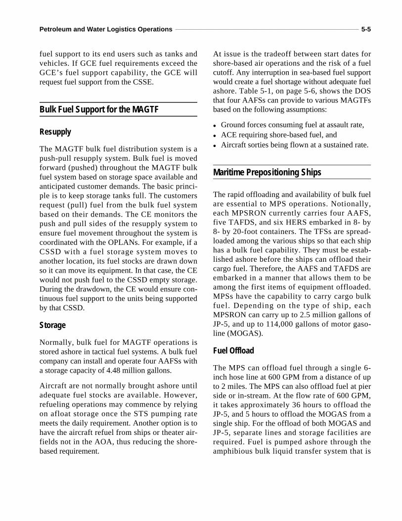
Petroleum and Water Logistics Operations ___________________________________________________________________ 5-5
fuel support to its end users such as tanks andvehicles. If GCE fuel requirements exceed theGCE’s fuel support capability, the GCE willrequest fuel support from the CSSE.
Bulk Fuel Support for the MAGTF
Resupply
The MAGTF bulk fuel distribution system is apush-pull resupply system. Bulk fuel is movedforward (pushed) throughout the MAGTF bulkfuel system based on storage space available andanticipated customer demands. The basic princi-ple is to keep storage tanks full. The customersrequest (pull) fuel from the bulk fuel systembased on their demands. The CE monitors thepush and pull sides of the resupply system toensure fuel movement throughout the system iscoordinated with the OPLANs. For example, if aCSSD with a fuel storage system moves toanother location, its fuel stocks are drawn downso it can move its equipment. In that case, the CEwould not push fuel to the CSSD empty storage.During the drawdown, the CE would ensure con-tinuous fuel support to the units being supportedby that CSSD.
Storage
Normally, bulk fuel for MAGTF operations isstored ashore in tactical fuel systems. A bulk fuelcompany can install and operate four AAFSs witha storage capacity of 4.48 million gallons.
Aircraft are not normally brought ashore untiladequate fuel stocks are available. However,refueling operations may commence by relyingon afloat storage once the STS pumping ratemeets the daily requirement. Another option is tohave the aircraft refuel from ships or theater air-fields not in the AOA, thus reducing the shore-based requirement.
At issue is the tradeoff between start dates forshore-based air operations and the risk of a fuelcutoff. Any interruption in sea-based fuel supportwould create a fuel shortage without adequate fuelashore. Table 5-1, on page 5-6, shows the DOSthat four AAFSs can provide to various MAGTFsbased on the following assumptions:
Ground forces consuming fuel at assault rate, ACE requiring shore-based fuel, and Aircraft sorties being flown at a sustained rate.
Maritime Prepositioning Ships
The rapid offloading and availability of bulk fuelare essential to MPS operations. Notionally,each MPSRON currently carries four AAFS,five TAFDS, and six HERS embarked in 8- by8- by 20-foot containers. The TFSs are spread-loaded among the various ships so that each shiphas a bulk fuel capability. They must be estab-lished ashore before the ships can offload theircargo fuel. Therefore, the AAFS and TAFDS areembarked in a manner that allows them to beamong the first items of equipment offloaded.MPSs have the capability to carry cargo bulkfuel. Depending on the type of ship, eachMPSRON can carry up to 2.5 million gallons ofJP-5, and up to 114,000 gallons of motor gaso-line (MOGAS).
Fuel Offload
The MPS can offload fuel through a single 6-inch hose line at 600 GPM from a distance of upto 2 miles. The MPS can also offload fuel at pierside or in-stream. At the flow rate of 600 GPM,it takes approximately 36 hours to offload theJP-5, and 5 hours to offload the MOGAS from asingle ship. For the offload of both MOGAS andJP-5, separate lines and storage facilities arerequired. Fuel is pumped ashore through theamphibious bulk liquid transfer system that is
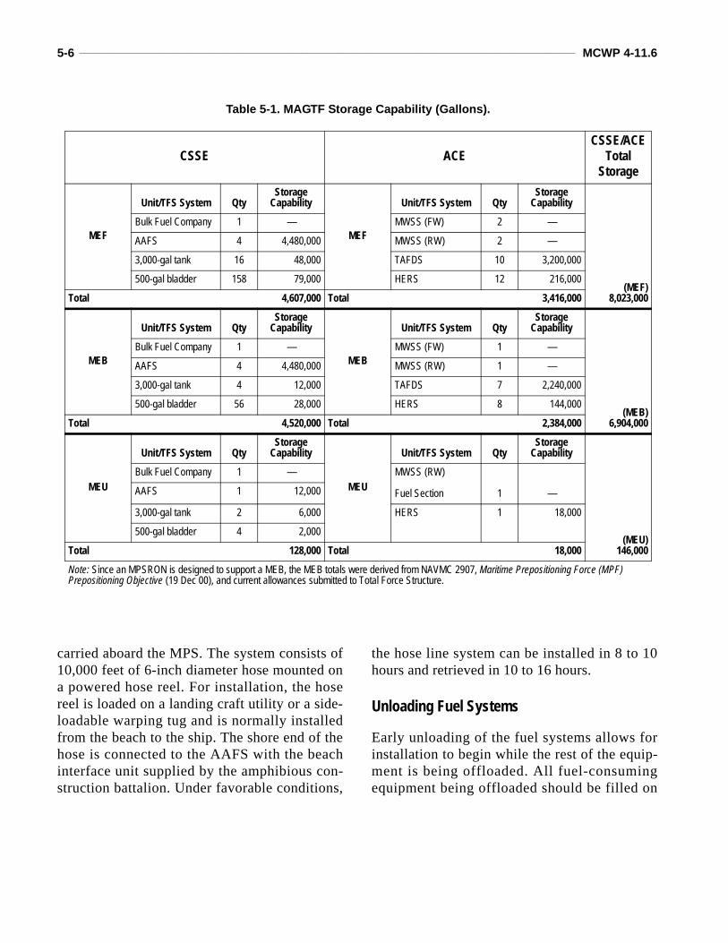
5-6 ____________________________________________________________________________________________________ MCWP 4-11.6
carried aboard the MPS. The system consists of10,000 feet of 6-inch diameter hose mounted ona powered hose reel. For installation, the hosereel is loaded on a landing craft utility or a side-loadable warping tug and is normally installedfrom the beach to the ship. The shore end of thehose is connected to the AAFS with the beachinterface unit supplied by the amphibious con-struction battalion. Under favorable conditions,
the hose line system can be installed in 8 to 10hours and retrieved in 10 to 16 hours.
Unloading Fuel Systems
Early unloading of the fuel systems allows forinstallation to begin while the rest of the equip-ment is being offloaded. All fuel-consumingequipment being offloaded should be filled on
Table 5-1. MAGTF Storage Capability (Gallons).
CSSE ACECSSE/ACE
Total Storage
MEF
Unit/TFS System QtyStorage
Capability
MEF
Unit/TFS System QtyStorage
Capability
(MEF)8,023,000
Bulk Fuel Company 1 — MWSS (FW) 2 —
AAFS 4 4,480,000 MWSS (RW) 2 —
3,000-gal tank 16 48,000 TAFDS 10 3,200,000
500-gal bladder 158 79,000 HERS 12 216,000
Total 4,607,000 Total 3,416,000
MEB
Unit/TFS System QtyStorage
Capability
MEB
Unit/TFS System QtyStorage
Capability
(MEB)6,904,000
Bulk Fuel Company 1 — MWSS (FW) 1 —
AAFS 4 4,480,000 MWSS (RW) 1 —
3,000-gal tank 4 12,000 TAFDS 7 2,240,000
500-gal bladder 56 28,000 HERS 8 144,000
Total 4,520,000 Total 2,384,000
MEU
Unit/TFS System QtyStorage
Capability
MEU
Unit/TFS System QtyStorage
Capability
(MEU)146,000
Bulk Fuel Company 1 — MWSS (RW)
Fuel Section 1 —AAFS 1 12,000
3,000-gal tank 2 6,000 HERS 1 18,000
500-gal bladder 4 2,000
Total 128,000 Total 18,000
Note: Since an MPSRON is designed to support a MEB, the MEB totals were derived from NAVMC 2907, Maritime Prepositioning Force (MPF) Prepositioning Objective (19 Dec 00), and current allowances submitted to Total Force Structure.
Petroleum and Water Logistics Operations ___________________________________________________________________ 5-7
the ships before offload. This will reduce theimmediate need for shore-based fuel support.Mobile refuelers should also be filled before off-loading so they can provide required fuel supportashore. Once the ship has offloaded its cargo, itcan then be positioned to deploy the hose reeland offload its cargo fuel to the AAFS. In thetime it takes to offload the equipment from theship and deploy the hose reel, the AAFS installa-tion should be to the point that it can start receiv-ing fuel . During si te select ion for MPSs,operations planners need to consider terrain
requirements and locations for the bulk fuel sys-tems and the STS fuel transfer.
Bulk Fuel Reports
Bulk fuel reporting requirements and procedureswill vary depending on the exercise and/or opera-tion. Appendices B and C are examples of bulkfuel reports that may be required of the MAGTFin a joint environment. The example in appendixB is from the defense message system.
CHAPTER 6. BULK FUEL INVENTORY MANAGEMENT
The management of fuel inventories involves afull range of actions associated with orders/requi-sitions, receipt, transfer, issue, and storage offuel. Bulk fuel support must be planned so prod-uct quantities are maintained to support plannedoperations. The major objectives of an inventorymanagement program are to—
Ensure all orders, receipts, transfers, issues,losses, gains, and adjustments are properlydocumented.Maintain accountable records on all products.Ensure an audit trail of fuel transactions is per-formed.Maintain control over the physical environ-ment to ensure proper product storage can takeplace with minimal losses.Ensure fuel losses are held to a minimum.
References
The requirements and procedures for the account-ability of petroleum products are in DOD Man-ual 4140.25-M. This reference provides policyand guidance for the accountability of petroleumproducts by Marine Corps activities.
Regardless of the type of fuel equipment beingused, units must maintain accounting proceduresand records as accurately as possible. Thisapplies to tactical situations using mobile refuel-ing equipment and TFSs. Accounting for fuel infixed facilities and commercial mobile equip-ment must be fairly accurate. However, whenbulk fuel units perform a physical inventory forTFSs, the physical inventory becomes more diffi-cult and less accurate due to the use of collapsibletanks and miles of tactical hose that may be
employed. The key to more accurate accountingfor TFSs is for commanders to ensure that localbulk fuel standing operating procedures (SOPs)address unit procedures and requirements for fuelaccountability when using TFSs.
Procedures
DOD fuel is purchased and owned at the whole-sale level by DESC for direct delivery to the cus-tomer. When the Service orders and receives fuelfrom a defense fuel supply point or a DESC con-tract, a “sale” may take place if the fuel is trans-ferred to single-user unit. If the fuel is transferredto a multi-user unit and that unit or site holdsDESC-owned (capitalized) fuel, a “sale” takesplace once the fuel is issued into the individualpiece of equipment or aircraft.
Whether a Service is holding wholesale or retailbulk fuel stocks, certain rules of accounting applyto all Services. All bulk fuel holding activitiesshould maintain a property book or logbookinventory record and a physical inventory record.Property book records are an administrative(checkbook) record of all receipts, transfers, andissues, and provide an estimate of the fuel inven-tory on hand. They are maintained on a dailybasis. Physical inventory is a physical measure-ment of the actual fuel on hand using volume cor-rection to 60 degrees Fahrenheit (F). A physicalinventory is conducted periodically (daily,weekly, monthly) depending on the situation. Ifthe differences between the property bookrecords and the physical inventory exceeds theallowable loss/gain, it must be reported throughthe chain of command.
6-2 ____________________________________________________________________________________________________ MCWP 4-11.6
Fuel Accountability
As with all supplies, the commander considers theaccountability of bulk fuel essential. Commandersare also aware that procedures and requirementsfor bulk fuel accountability will vary depending onthe operation, the type of fuel equipment beingused, and the situation; for example, combat, train-ing exercise or joint operation. To ensure properand sound accounting procedures are being fol-lowed, the commander and staff need to ensurethat accounting procedures are contained inOPLANs and exercise letters of instruction.
However, due to the nature of fuel, certainlosses will occur as a result of evaporation,transportation, storage, and handling. Allowabletolerances have been established for these lossesand gains by the American Petroleum Institute(API) and adopted by the DOD. There are manyvariables involved in accounting procedures.The following procedures are common andapply to all bulk fuel operations:
Access to all bulk fuel stocks must be controlled. The quantity and quality of fuel receipts shouldbe validated prior to off-loading.
The unit of measurement for all fuel receipts is theUS gallon corrected for volume to 60 degrees F.Discrepancies in excess of allowable losses/gains must be documented and reported.Only authorized personnel should make fuelissues.
Reports
Status reports; daily, weekly, monthly fuels issuereports; and monthly bulk fuel accounting sum-maries are used to maintain accountability of bulkfuel receipts, issues, and stocks on hand. Reportcontent should include the following:
Opening and closing balances.Total issues.Total receipts.Physical inventory.Property book inventory.Losses/gains.Other applicable information regarding account-ing or operational capability.
Daily status reports, including the bulk petro-leum contingency report (REPOL), are done perthe local commander’s SOP. See appendix C fora REPOL example.
CHAPTER 7. BULK FUEL QUALITY SURVEILLANCE PROGRAM
Quality surveillance is the process of determin-ing and maintaining the quality of petroleumand related products to ensure these productsare suitable for their intended use. The qualityof petroleum products is controlled at origin bythe DESC. After receipt of the petroleum prod-ucts, each Service is responsible for continuedsurveillance to maintain the quality of petro-leum products.
To meet specifications set by DOD, petroleumproducts undergo quality surveillance from timeof purchase until used. The JPO, responsible tothe JFC, ensures there is a quality surveillanceprogram within the command and monitors andassists Service components in this program. Thetheater Army command is responsible for settingup and maintaining a quality surveillance pro-gram to support theater Army users. Each Servicecomponent is responsible for establishing andmaintaining a quality surveillance program forService-held petroleum stocks.
A vigilant quality surveillance program imple-mented by properly trained personnel is neces-sary to protect the original product quality. Thefuel systems of modern aircraft and ground vehi-cles will not function properly if fuel is contami-nated with dirt, water, other fuel, or any foreignmatter. Actions will be taken to ensure that theproduct conforms to established technical speci-fications. These actions include preventive main-tenance of equipment; mandatory use of filterseparators for aviation fuels (also highly recom-mended for ground fuels); daily recirculation andvisual examination of the product; proper stor-age, handling, and drainage of water bottoms;
and monitoring proper concentrations of addi-tives. The DOD-MIL-STD 3004A and NAVAIR00-80T-109 are the approved references for qual-ity surveillance.
Personnel
The bulk fuel officer (military occupational spe-cialty [MOS] 1390) or the bulk fuel staff non-commissioned officer (MOS 1391) is responsiblefor establishing procedures that will ensure thequality of bulk fuel products that are stored andissued. All fuel handling personnel are responsi-ble for following established procedures andensuring they take the required steps to deliverclean fuel to vehicles and aircraft.
An effective quality surveillance programrequires properly trained personnel. EveryMarine involved in handling petroleum should besuitably trained in quality control. The activityhaving physical possession of a product isresponsible for quality surveillance.
Specifications
Various types of fuel have critical properties andrequirements that must be maintained. Testsdetermine a product’s physical and chemicalproperties. Each petroleum product has a specifi-cation that lists chemical and physical require-ments of the fuel. The specifications listed intables 7-1 and 7-2 on page 7-2 are common gov-ernment-owned fuels in use by the military today.
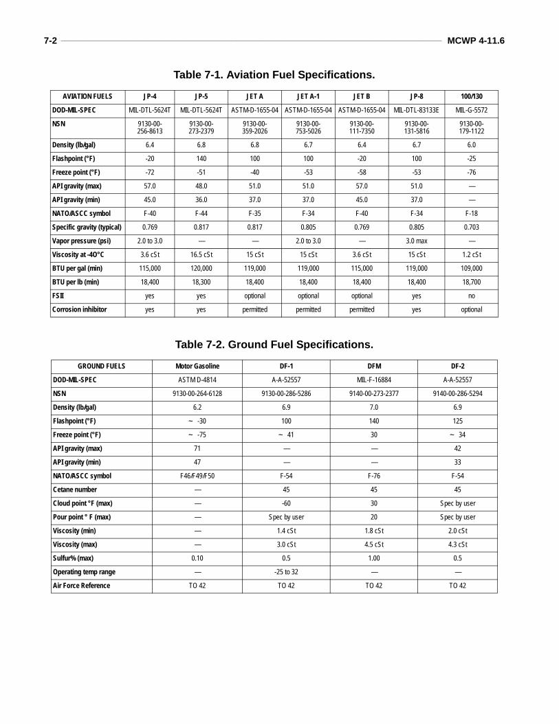
7-2 ____________________________________________________________________________________________________ MCWP 4-11.6
Table 7-1. Aviation Fuel Specifications.
Table 7-2. Ground Fuel Specifications.
AVIATION FUELS JP-4 JP-5 JET A JET A-1 JET B JP-8 100/130
DOD-MIL-SPEC MIL-DTL-5624T MIL-DTL-5624T ASTM-D-1655-04 ASTM-D-1655-04 ASTM-D-1655-04 MIL-DTL-83133E MIL-G-5572
NSN 9130-00-256-8613
9130-00-273-2379
9130-00-359-2026
9130-00-753-5026
9130-00-111-7350
9130-00-131-5816
9130-00-179-1122
Density (lb/gal) 6.4 6.8 6.8 6.7 6.4 6.7 6.0
Flashpoint (°F) -20 140 100 100 -20 100 -25
Freeze point (°F) -72 -51 -40 -53 -58 -53 -76
API gravity (max) 57.0 48.0 51.0 51.0 57.0 51.0 —
API gravity (min) 45.0 36.0 37.0 37.0 45.0 37.0 —
NATO/ASCC symbol F-40 F-44 F-35 F-34 F-40 F-34 F-18
Specific gravity (typical) 0.769 0.817 0.817 0.805 0.769 0.805 0.703
Vapor pressure (psi) 2.0 to 3.0 — — 2.0 to 3.0 — 3.0 max —
Viscosity at -4O°C 3.6 cSt 16.5 cSt 15 cSt 15 cSt 3.6 cSt 15 cSt 1.2 cSt
BTU per gal (min) 115,000 120,000 119,000 119,000 115,000 119,000 109,000
BTU per lb (min) 18,400 18,300 18,400 18,400 18,400 18,400 18,700
FSII yes yes optional optional optional yes no
Corrosion inhibitor yes yes permitted permitted permitted yes optional
GROUND FUELS Motor Gasoline DF-1 DFM DF-2
DOD-MIL-SPEC ASTM D-4814 A-A-52557 MIL-F-16884 A-A-52557
NSN 9130-00-264-6128 9130-00-286-5286 9140-00-273-2377 9140-00-286-5294
Density (lb/gal) 6.2 6.9 7.0 6.9
Flashpoint (°F) ~ -30 100 140 125
Freeze point (°F) ~ -75 ~ 41 30 ~ 34
API gravity (max) 71 — — 42
API gravity (min) 47 — — 33
NATO/ASCC symbol F46/F49/F50 F-54 F-76 F-54
Cetane number — 45 45 45
Cloud point °F (max) — -60 30 Spec by user
Pour point ° F (max) — Spec by user 20 Spec by user
Viscosity (min) — 1.4 cSt 1.8 cSt 2.0 cSt
Viscosity (max) — 3.0 cSt 4.5 cSt 4.3 cSt
Sulfur% (max) 0.10 0.5 1.00 0.5
Operating temp range — -25 to 32 — —
Air Force Reference TO 42 TO 42 TO 42 TO 42
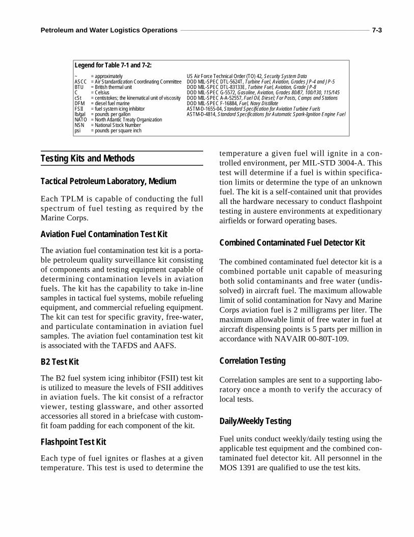
Petroleum and Water Logistics Operations ___________________________________________________________________ 7-3
Testing Kits and Methods
Tactical Petroleum Laboratory, Medium
Each TPLM is capable of conducting the fullspectrum of fuel testing as required by theMarine Corps.
Aviation Fuel Contamination Test Kit
The aviation fuel contamination test kit is a porta-ble petroleum quality surveillance kit consistingof components and testing equipment capable ofdetermining contamination levels in aviationfuels. The kit has the capability to take in-linesamples in tactical fuel systems, mobile refuelingequipment, and commercial refueling equipment.The kit can test for specific gravity, free-water,and particulate contamination in aviation fuelsamples. The aviation fuel contamination test kitis associated with the TAFDS and AAFS.
B2 Test Kit
The B2 fuel system icing inhibitor (FSII) test kitis utilized to measure the levels of FSII additivesin aviation fuels. The kit consist of a refractorviewer, testing glassware, and other assortedaccessories all stored in a briefcase with custom-fit foam padding for each component of the kit.
Flashpoint Test Kit
Each type of fuel ignites or flashes at a giventemperature. This test is used to determine the
temperature a given fuel will ignite in a con-trolled environment, per MIL-STD 3004-A. Thistest will determine if a fuel is within specifica-tion limits or determine the type of an unknownfuel. The kit is a self-contained unit that providesall the hardware necessary to conduct flashpointtesting in austere environments at expeditionaryairfields or forward operating bases.
Combined Contaminated Fuel Detector Kit
The combined contaminated fuel detector kit is acombined portable unit capable of measuringboth solid contaminants and free water (undis-solved) in aircraft fuel. The maximum allowablelimit of solid contamination for Navy and MarineCorps aviation fuel is 2 milligrams per liter. Themaximum allowable limit of free water in fuel ataircraft dispensing points is 5 parts per million inaccordance with NAVAIR 00-80T-109.
Correlation Testing
Correlation samples are sent to a supporting labo-ratory once a month to verify the accuracy oflocal tests.
Daily/Weekly Testing
Fuel units conduct weekly/daily testing using theapplicable test equipment and the combined con-taminated fuel detector kit. All personnel in theMOS 1391 are qualified to use the test kits.
Legend for Table 7-1 and 7-2:~ ASCC BTU C cSt DFMFSII lb/gal NATO NSN psi
= approximately= Air Standardization Coordinating Committee= British thermal unit= Celsius= centistokes; the kinematical unit of viscosity= diesel fuel marine= fuel system icing inhibitor= pounds per gallon= North Atlantic Treaty Organization= National Stock Number= pounds per square inch
US Air Force Technical Order (TO) 42, Security System DataDOD MIL-SPEC DTL-5624T, Turbine Fuel, Aviation, Grades JP-4 and JP-5DOD MIL-SPEC DTL-83133E, Turbine Fuel, Aviation, Grade JP-8DOD MIL-SPEC G-5572, Gasoline, Aviation, Grades 80/87, 100/130, 115/145DOD MIL-SPEC A-A-52557, Fuel Oil, Diesel; For Posts, Camps and StationsDOD MIL-SPEC F-16884, Fuel, Navy DistillateASTM-D-1655-04, Standard Specification for Aviation Turbine FuelsASTM-D-4814, Standard Specifications for Automatic Spark-Ignition Engine Fuel
7-4 ____________________________________________________________________________________________________ MCWP 4-11.6
Deterioration Limits
Bulk fuel deteriorates when subject to long peri-ods of storage. Therefore, it is important that bulkfuel be issued on a first-in, first-out basis or asquality surveillance indicates. Deteriorationoccurs when one or more characteristics of theproduct change to a level outside the specificationlimits. Examples of deterioration are weathering,oxidation, or loss of additives.
Deterioration limits are tolerances established topermit use of products that do not fully meetspecifications. When petroleum products do notmeet the deterioration limits, quality surveillancepersonnel report the facts and circumstances andrecommend alternative use or disposition to thecommanding officer. If appropriate, proposedrecovery measures are also reported.
Testing Properties
Knock Values
Knock values indicate whether a fuel will burnuniformly and evenly in a cylinder without pre-ignition or detonation. The knock values areexpressed as octane numbers for automotivetype engine gasoline and as a combination ofoctane and performance numbers for aviationgasoline. These values are determined by com-paring the knocking tendency of fuel samples tothose of standard test fuels of known knock val-ues in a standard test engine. Fuel of inadequateknock value will reduce the power output of alltypes of engines. If used for more than briefperiods, it could cause overheating of theengine, burned or melted pistons and cylinders,and lubrication failure.
Cetane Number
The ignition quality of a diesel fuel, which isbased on a scale resembling that of an octane
number, is expressed as a cetane number. Thisnumber indicates the length of time (ignition lag)between injection of the fuel and combustion.The cetane number requirement varies with thetype of diesel engine. Large and slow speed unitsin stationary installations do not require dieselfuel with cetane ratings above 40. Smaller, high-speed engines (1,000 rotations per minute ormore) require fuel of a higher cetane number. Inthe absence of test engines, cetane numbers areapproximated from the calculated cetane index.
Color
Color is primarily used as an aid for identifyingfuels such as aviation and automotive gasolinesthat have characteristic colors. Failure of fuel tomeet its color requirement may indicate the possi-bility of contamination or deterioration. Darken-ing of the color of jet fuel may indicate theformation of insoluble gums.
Corrosion
Quantitative and qualitative tests for corrosionindicate whether products are free of corrosion ten-dencies. The quantitative test determines total sul-fur content. This is important, particularly when aproduct is to be burned in lamps, heating appli-ances, or engines. The qualitative test shows if fuelwill corrode the metal parts of fuel systems.
Existent Gum
As the name implies, gum is the sticky, tacky,varnish-like material that is undesirable to have infuel systems. Existent gum is the nonvolatile resi-due present in gasoline or jet fuels after they havebeen tested. The results indicate the quantity ofgum deposit that may occur if the product is usedimmediately but do not indicate the possibility ofgum formation when the product is stored. Whenpresent in excess, gum clogs fuel lines, filter andpump screens, and carburetor jets; causes mani-fold deposits and sticky intake valves; andreduces the knock value of gasoline.
Petroleum and Water Logistics Operations ___________________________________________________________________ 7-5
Potential Gum
Potential gum (sometimes called oxidation stabil-ity) is determined by a test that indicates the pres-ence of gum-forming materials and the relativetendency of gasolines and jet fuels to form gumsafter a specified period of accelerated aging. Thisvalue is used as an indication of the tendency offuels to form gum during extended storage.
Retention of the original properties of a fuel afterprolonged storage is known as the stability of thefuel. When added to fuels, chemical inhibitorsretard gum formation but will not reduce gum thathas already been formed. The effects of the poten-tial gum are similar to those described for existentgum. Gum may be expressed as the “inductionperiod” (sometimes called the breakdown time).This is a measure of the time in minutes that elapseduring the accelerated test until the fuel rapidlyabsorbs oxygen. For aviation gasoline and jet fuel,the potential gum may be expressed as the poten-tial for accelerated gum. This is the gum plus thelead deposits (from lead fuels) measured at the endof a specified accelerated aging (oxidation) period.
Flashpoint
The flashpoint is the lowest temperature at whichvapors rising from a petroleum product (or whenexposed to test flame under specified conditions)ignite momentarily (flash) on application. Theflashpoint of a petroleum product indicates thefire hazard in handling and storing it. It applies tofuel oils, diesel fuels, JP-5, kerosene, and sol-vents. It is not used for JP-4. The flashpoint testalso indicates the combination of a product. Forexample, the presence of very small quantities ofgasoline will make the flashpoint of a diesel fuelconsiderably lower than the minimum operatinglevel. The flashpoint of new lubricating oil isused primarily for identification and classifica-tion. The flashpoint of the oil must be above theoperating temperature of the engine in which it isto be used.
Cloud and Pour Points
The cloud point is the temperature at which waxcrystals (normally held in solution or water) in oilseparate, causing the oil to appear cloudy or hazy.In wick-fed systems, the wax crystals may clogthe wick. Both wax crystals and water may blockfilter passages in fuel systems. The pour point ofoil indicates its behavior at low temperature. Thefact that oil has a specific pour point is no guar-antee that it can be handled or is a satisfactorylubricant at that temperature.
Distillation
The distillation process is used to measure thevolatility of a petroleum product. The lower boil-ing fractions of gasoline indicate the starting abil-ity of a gasoline engine at a given temperatureand the engine’s ability to warm up quickly. Anexcessive amount of highly volatile constituentsin gasoline may cause vapor lock. Conversely, agasoline with an excessive amount of “heavyends” may not completely burn in the combustionchamber. This may cause damage through exces-sive dilution of crankcase oil. Specifications des-ignate minimum and maximum percentages offractions to be evaporated at specified tempera-tures, as well as initial and final boiling points. Agasoline with a high end point and a high percent-age of residues may be contaminated with fueloils or other oils. A fuel oil with a considerablylower initial boiling point flashpoint than normalmay be contaminated with gasoline.
Viscosity
Viscosity is the measure of a liquid’s resistanceto flow. Specified minimum and maximum flowrates are required for all fuel oils and lubricat-ing oils. A fuel oil’s viscosity determines howthe oil will flow to the burners, the extent towhich it would be atomized, and the temperatureat which the oil must be maintained to be atom-ized properly.
7-6 ____________________________________________________________________________________________________ MCWP 4-11.6
Reid Vapor Pressure
The vapor pressure of a fuel, which indicates thetendency to vaporize, is determined by the Reidvapor test. For any given gasoline, vapor pres-sure increases with temperature. Gasolines musthave a certain vapor pressure to ensure adequatestarting and accelerating qualities.
Carbon Residue
The carbon residue test indicates the carboniz-ing properties of lubricating or burner oil. How-ever, carbon residue from lubricating oils is notdirectly related to carbon formation in theengine. This test gives an indication of the typeof carbon formation (loose or flaky or hard andflinty). It is used primarily as an identify-and-control test in conjunction with other specifica-tion tests. After distilling 90 percent of dieselfuel, the carbon remaining in the 10 percent resi-due must be low enough to avoid carbon depos-i ts . High carbon fuels should be checkedcarefully for carbon formation.
Bottom Sediment and Water
Petroleum products may gain sediment and waterduring storage and handling. This can adverselyaffect the performance of the equipment in whichthe products are used.
Aviation Fuels Contamination by bottom sediment and water canoften be detected visually. As a general rule, avi-ation fuel must be clean and bright and contain nofree water. The terms clean and bright do notrefer to the natural color of the fuel; the variousgrades of the fuel have dyes added. Jet fuels arenot dyed and could be any color from water whiteto amber. “Clean” means the absence of anycloud, emulsion, readily visible sediment, orentrained water. “Bright” refers to the shinyappearance of clean dry fuels. Clouds, haze,specks of sediment, or entrained water indicatethat the fuel is unsuitable, pointing to a break-down of fuel handling equipment. Steps should
be taken to find the trouble immediately. NOTE:All the following information is also applicable toautomotive fuels.
Cloudy or Hazy FuelCloudy or hazy fuel usually indicates water, but itmay also indicate excessive amounts of fine sedi-ment or finely dispersed stabilized emulsion. Fuelcontaining either is not acceptable. When cleanand bright fuel cools, a light cloud may formindicating that dissolved water has precipitatedout. A precipitation cloud represents a very slightamount of fresh water. However, even a slightamount of fresh water is not desirable in aviationfuel. Fuel that shows some precipitation may notbe clean and cannot be accepted or used. Filterseparator elements should be replaced and waterand emulsion should be removed from the sourcetank. A filter/separator can be used to remove theprecipitation by recirculation or by draining thefuel upstream.
Sediment in FuelSpecks or granules of sediment indicate particlesin size range greater than 0.8 microns. An appre-ciable number of such particles in a sample indi-cate a failure of the filter/separator, or a dirtysample container. Even with the most efficientfilter/separator and careful fuel handling, an occa-sional visible particle will be noted. The sedimentordinarily noted is an extremely fine powder,rouge, or silt. In a clean sample of fuel, sedimentshould not be visible. If sediment continues to benoted, appropriate surveillance tests and correc-tive measures must be applied to the fuel han-dling systems.
Diesel Fuels and Burner OilsTo avoid fuel pump and injector difficulties, die-sel fuels must be clean and should not containmore than a trace of foreign substances. Exces-sive sediment and rust in burner oils will plug theburner tip, and the fuel will not atomize properly.Water can cause ragged operation and may cor-rode the fuel handling system. The types of
Petroleum and Water Logistics Operations ___________________________________________________________________ 7-7
equipment and burner oils will determine theamount of sediment permissible in the fuel.
Lubricating Oils
Care should be taken to avoid contaminatinglubricating oils with water. Water will hastendecomposition of many oils, wash out additives,cause the oil to emulsify, and lead to engine fail-ure. In used lubricating oils, sediment and watermay have been caused by poor maintenance, fail-ure of screens, or by condensation of combus-tion products.
Ash
Burning off the organic matter and weighing theremaining inorganic matter determine the ash inoil. Straight mineral oils usually contain a smalltrace of ash. Oils containing metallic salts asadditives will have larger amounts of ash.Increased amounts of ash indicate contaminationwith inorganic matter such as sand, dust, and rust.Increased ash in straight mineral oils may indi-cate contamination with additive type oils. Theash in diesel fuels must be very low because anyabrasive substances may damage the internalmetal surfaces of the engines and may formdeposits on working surfaces. Residual fuel oilsshould also have low amounts of ash to preventcorrosion or embrittlement of fireboxes andboiler tubes.
Foam Stability
All oils will foam to some extent when agitated.The foam that is formed in oils that contain addi-tives is often very stable. Instead of breaking upquickly, the foam tends to build up, and oil is lostthrough the breather outlets and other openings inthe engine crankcase. Therefore, additive-typemotor oils are frequently treated with antifoamagents to eliminate potential foam problems. Thefoam test requires agitating the oil until the foamis formed and then noting the time required forthe foam to break up and disappear.
Gravity
Accurate determination of the gravity of petro-leum is necessary for converting measured vol-umes to volumes of the standard temperature of60 degrees F. Gravity is a factor governing thequality of crude oils. However, the gravity of apetroleum product is an uncertain indication of itsquality. Combined with other properties, gravitycan be used to give approximate hydrocarboncomposition and heat of combustion. The gravityscale most used in the US is the API gravity. Achange of gravity may indicate a change of com-position caused by mixing grades of products.
Water Reaction
This test determines the presence of water-misci-ble components in aviation gasolines and turbinefuels, and the effects of these components on thefuel-water interface.
Fuel System Icing Inhibitor Test
This is a quantitative test used to determine theconcentration of the FSII in jet fuel. The FSIIadditive (ethylene glycol monomthyl ether-glyc-erol) prevents ice formation in aircraft fuel sys-tems. Testing is performed by many methods(such as colormetric, seisor refractometer, freez-ing point, and titration). The potassium dichro-matesulfuric acid titremetric procedure is themethod preferred by the Air Force.
Water Separometer Index Modified
The water separometer index modified test mea-sures the ease with which a fuel releases dis-persed or emulsified water. Fuels having a lowwater separometer index modified rating will pre-vent filter/separators from functioning properly.
Particulate Contaminant
Excessive sediment will clog fuel lines and inter-nal fuel filters on aircraft. Sediment may also causewear on metal parts and, when burned, may form
7-8 ____________________________________________________________________________________________________ MCWP 4-11.6
deposits causing premature engine failure. The twotests for particulate contaminant in aviation turbinefuels are the Millipore test and the color compari-son standards test (the Air Force method).
Undissolved Water
Undissolved (free) water in aviation fuels canencourage the growth of microorganisms and sub-sequent corrosion in aircraft tanks. It can also leadto icing of filters in the fuel system. Free water iscontrolled in ground fueling equipment by filter/separators. The Aqua-Glo test is a quick and accu-rate way to determine the amount of free water inliquid petroleum products. The procedure is foundin ASTM D-3240-91 (2001), Standard TestMethod for Undissolved Water in Aviation Tur-bine Fuels. Water in fuel can cause the followingsevere problems:
Corrosion of tanks, equipment, and lines due tothe formation of hydrogen sulfide, an extremelycorrosive compound.Removal of FSII from aviation turbine fuels. Clogging of fuel lines and filters, particularlyat high altitudes. Support of microbiotic growth sometimes foundin water and fuel interface in jet tanks.
Reclamation
Reclamation is the process of restoring or chang-ing the quality of an unsuitable product to meetquality assurance specifications. Fuel can be
reclaimed for use by downgrading, blending,purifying, or removing water. Captured fuelshould be exploited whenever possible to reducethe logistical burden, but only after testing is per-formed by a qualified person. The intended use ofcaptured fuel will dictate the extent of testing.
Fuel that cannot be used for its intended purposemay be used as a lower grade of the same or simi-lar product if it meets that product’s specifications.
The most common causes of off-specificationfuel are contamination and deterioration. Con-tamination occurs when one or more grades ortypes of products are inadvertently mixed, or aproduct contains foreign matter such as dirt, dust,rust, water, or emulsions. Once a product hasbeen identified as being off-specification, the fol-lowing reclamation procedures can be taken:
Downgrading. Approval for an off-specifica-tion or contaminated product for other than itsintended use.Blending. Predetermined quantities of two ormore similar products are mixed to produce apetroleum product or intermediate grade orquality.Purification. The removal of contaminatingagents by filtration or dehydration.Dehydration. The removal of water by a filter-ing or settling process. Water in most lightproducts will settle out if allowed to standundisturbed for 12 to 24 hours.Inhibiting. Adding or restoring additives.Disposal. As per local SOP.
PART II. BULK WATER OPERATIONS
CHAPTER 8. FUNDAMENTALS
Potable water supply has always been a criticalfactor on the battlefield. A lack of water candemoralize and debilitate personnel. Three of thefour major causes of death in the Civil War weredue to contaminated water. With the discovery ofbacteria, scientists began to understand that con-taminated water caused diseases and infectedwounds. A lack of water can also determine theoutcome of a war. In 1915, the British commanderat Gallipoli, Lieutenant General Sir FrederickStopford, and his commander, who were activelyinvolved in the landing at Suvla Bay, believed thatthe shortage of water was the major cause for theirfailure to take the heights before the Turks occu-pied them in force.
Improvements to Water Support
The Marine Corps is constantly seeking toimprove its water support capability to meet theneeds of the Marine Corps and if necessary, theneeds of other Services. Consumption factorshave been developed to assist in planning for ade-quate water support and new equipment has beendeveloped to purify all sources of water, toinclude nuclear, biological, and chemical (NBC)contaminated water. Through the latest technol-ogy, quality, and expedient training, the bulkwater units are better prepared to provide Marinesa most valuable commodity—water.
Concept of Bulk Water Operations
The basic concept of bulk water support is tosource or produce water as close to the user aspossible. This requires proper planning of the
wate r po in t se lec t ion fo r bu lk wa te r , i frequired, and purification, storage, and distri-bution of bulk water.
Bulk Water Support Responsibility
Bulk water support is normally a Service respon-sibility. However, during joint operations, theJFC may assign the responsibility for water sup-port based on the predominant user concept. Thismeans that the greatest volume user in an areawould provide bulk water support above andbeyond the organic Service capabilities to allforces operating in the area. The actual proce-dures used to provide bulk water support to theServices will depend on conditions in the AO.
Deployments
In most deployments, Marine Corps forces willbe capable of partial or complete water self-suffi-ciency using organic water equipment and HN orcommercial support. In geographic regions withadequate surface water resources, the com-mander is likely to establish multiple water pointsin the vicinity of his forces.
Production and Storage
The production of water is the purification ofexisting water sources into potable water. Theextent to which a water point is developeddepends primarily on the time, materials, and thepersonnel available to do the work. Water stor-age should be sufficient to meet the dailydemands and allow water production to continue.Having adequate water storage avoids frequenttime-consuming start-ups and shutdowns of thewater production equipment.
8-2 ____________________________________________________________________________________________________ MCWP 4-11.6
Distribution
In most situations, water distribution is the weaklink of the water support system. Getting waterfrom the production and storage sites to the usercan be equipment and manpower intensive. Water
should be produced as close to the end user aspossible. Marine forces must make efficient useof all available assets in conducting water distri-bution operations. Getting water from the storagesite to the using units can involve utilizing allorganic water distribution assets.
CHAPTER 9. WATER EQUIPMENT
Marine Corps water equipment has to meet awide range of requirements, from providing sup-port for near shore operations to supportinginland operations. To meet these requirements,the Marine Corps has developed various waterequipment end items and the family of water sup-ply support equipment. USMC equipment has thecapability to purify both freshwater and saltwater.However, the Marine Corps does not have anorganic well drilling capability. The MAGTFmust be augmented by elements from the navalconstruction force in order to have this capability.
Water Equipment End Items
Shower Unit
The shower unit (TAMCN B0055) consists of sixseparate, identical, and interchangeable showermodules with interconnecting hoses, electric feedwater and drain pumps, and a drain hose. The unithas a self-contained, oil-fired boiler water heatercapable of providing 120-degree F water at a rateof 20 GPM.
Field Laundry Unit
The bare base laundry facility is a pallet-mounted, self-contained unit consisting of anelectrical panel, washer, extractor, dryer, air com-pressor, water pump, clothes bin, and waterheater. Those components are mounted on twoplatforms, which have 463L pallet locking railassemblies. The M-80 water heater, supplied withthe laundry unit, is a self-contained fuel-firedassembly capable of providing 120-degree Fwater at a rate of 20 GPM. The laundry unit pro-vides the capability to launder fabrics worn by
individual Marines and organizational items witha maximum output of 120 pounds per hour.
Reverse Osmosis Water Purification Unit
The reverse osmosis water purification unit(ROWPU) is an ISO frame-mounted, portablewater purification system capable of purifyingalmost any type of water, to include freshwater,brackish water, and saltwater. The ROWPU iscapable of removing NBC contaminants, miner-als, and biological impurities. The single greatestbenefit of the reverse osmosis process is the abil-ity to desalinate seawater. The ROWPU is pow-ered by a 30-kilowatt generator set and is capableof producing potable water at a rate of 600 GPH.
Tactical Water Purification System
The tactical water purification system (TWPS)will replace the aging 600-GPH ROWPU at a 1:2ratio. The TWPS is a fully contained, skid-mounted water purification system capable ofpurifying, storing, and dispensing water meetingTri-Service Field Water Quality Standards forlong-term consumption. The TWPS is poweredby a 60-kilowatt generator set and is capable ofproducing up to 1,500 GPH of potable water inan expeditionary environment. The TWPS canpurify a broad range of water sources, to includefreshwater, brackish water, and saltwater. It canalso purify water that has been exposed to NBCwarfare agents. The TWPS has five extendedcapabilities modules packaged separately in reus-able boxes:
Cold weather module. Supplemental module. Ocean intake structure system module. NBC water treatment module.NBC survivability module.
9-2 ____________________________________________________________________________________________________ MCWP 4-11.6
Medium Freshwater Purification Unit
The medium freshwater purification unit (LMT3000) is a portable, self-contained water purifica-tion unit for purifying turbid and bacteria pollutedfreshwater. It provides a method of producingpotable water at the rate of 1,500 to 3,000 GPH.The system contains all functional apparatus andsupplies to process approximately 20,000 gallonsof potable water per day once the user has a watersource and storage capability.
Water Quality Analysis Set-Purification
The water quality analysis set-purification(WQAS-P) consists of the equipment necessaryfor testing water quality. It is self-contained in aportable, waterproof suitcase. The WQAS-P isused to test total dissolved solids, oxygen reduc-tion potential, pH, chlorine, conductivity, resis-tivity, turbidity, and temperature. These factorsdetermine if a raw water source is suitable for useand they impact the efficiency of the water purifi-cation equipment. The digital technology usedassigns a numeric value to each item tested sothat different water sources can be compared tosee which is better in terms of water quality. TheWQAS-P may also contain the optional M272chemical agents water testing kit.
M149 Water Trailer
The M149 water trailer can transport 400 gallonsof potable and non-potable water over highwaysand cross-country terrain. The water tank is con-structed of stainless steel with double walls. Twoinches of urethane foam is used as insulationbetween the walls. It is equipped with four dis-pensing faucets and one drain faucet. A manholeis located on the top of the water tank for fillingand cleaning. The trailer is also equipped with abracket at the manhole to allow for heating of thewater with the standard M67 immersion heater.The trailer can be towed on highways at 50 milesper hour and cross-country at 30 miles per hourby a 2-1/2 ton vehicle or larger.
SIXCON Water Pump Module
The S IXCON wa te r p u m p m o d u l e i s acomponent of the SIXCON system—a modulesystem consisting of five tank modules and onepump module. The six modules attach together toform an ISO/American National StandardsInstitute configured 8- by 8- by 20-foot module.The SIXCON water pump module has thecapability for dispensing potable and non-potablewater. It has a 125 GPM pumping rate andincludes ancillary components for two dispensingpoints. It is used with the SIXCON water storagemodule. The SIXCON water modules can beused as a mobile water-dispensing asset or as astationary dispensing capability.
SIXCON Water Storage Module
The SIXCON water s to rage module i s acomponent of the SIXCON system—a modulesystem consisting of five tank modules and onepump module. The six modules attach together toform an ISO/American National StandardsInstitute configured 8- by 8- by 20-foot module.The SIXCON water storage module is a stainlesssteel tank encased within the module frame andhas a capacity of 900 gallons. The water tank iscovered with at least 1 inch of foam insulation tokeep stored water from freezing or heating up. Ithas the ancillary components necessary for inter-connecting to other SIXCON water storagemodules and the SIXCON water pump module(USMC TAMCN B1581). The SIXCON watermodules can be used as a mobile water-dispensingasset or as a stationary dispensing capability.
Family of Water Supply Support Equipment
To provide flexible and responsive water sup-port, the Marine Corps has developed a familyof water supply support equipment (WSSE).Each system is designed and configured specifi-cally to support a unique mission using similar

Petroleum and Water Logistics Operations ___________________________________________________________________ 9-3
components. The ability to alter fundamentalsystem configurations and the interchangeabil-ity of components allow the creation of limit-less combinations of tailored systems to meetmission requirements. The family of WSSE con-sists of 22 TAMCNs. Current allowances ofthese items can be found in the unit’s table oforganization and equipment.
500-Gallon Collapsible Potable Water Drum
The 500-gallon collapsible potable water drumis a durable, non-vented, hermetically sealed,collapsible fabric container of four-ply construc-tion used to store and transport potable water.When filled to its 500-gallon capacity, the drumis cylindrical in shape and can be towed andlifted by means of a towing and lifting yoke(USMC TAMCN B2730). The 500-gallon col-lapsible potable water drum is used with the for-ward area water point supply system (FAWPSS)(TAMCN B0676).
3,000-Gallon Collapsible Fabric Water Tank
The 3,000-gallon collapsible fabric water tank isused for storage of potable and non-potable waterin support of WSSE, tactical water purificationsystems, and general water storage. It is con-structed of impregnated fabric and designed forquick setup/teardown. The tank is equipped witha removable cover, flotation ring, repair kit,ground cloth, and two 2-inch valves.
20,000-Gallon Collapsible Water Tank The 20,000-gallon collapsible water tank is con-structed of impregnated fabric and equipped with4-inch elbow hose connections for storage,receipt, and issue of bulk water. The 20,000-gal-lon collapsible water tank assembly includes analuminum tank chest, ground cloth, emergencyrepair kit, and required components for ventingand draining.
50,000-Gallon Collapsible Water Tank
The 50,000-gallon collapsible water tank is con-structed of impregnated fabric and equipped with4-inch elbow hose connections for storage,receipt, and issue of bulk water. The 50,000-gal-lon collapsible water tank assembly includes analuminum tank chest, ground cloth, emergencyrepair kit, and required components for ventingand draining.
Forward Area Water Point Supply System
The FAWPSS is a portable, self-contained waterdispensing system for potable water. It consists ofa 125-GPM pump, hoses, and ancillary compo-nents necessary to establish four distributionpoints. The FAWPSS is used in conjunction withthe 500-gallon collapsible potable water drum(USMC TAMCN B0571).
Hypochlorination Unit, Purification
The hypochlorination unit, purification providesthe capability to chlorinate water to levels accept-able for consumption. It is designed to mix a pro-portional amount of hypochlorite solution(sanitizing agent) with water in the tactical waterdistribution system (TWDS). The unit may bepositioned in the TWDS so that water is chlori-nated prior to entering the storage tank or beforedelivery to the user. It is skid-mounted anddesigned to operate at 2 to100 GPM. It is associ-ated with the TWDS and tank farm interconnec-tion sets.
350-GPM Water Pump
The 350-GPM water pump assembly is designedspecifically to transfer water, and is the primarypump within the water supply tank farm. It con-sists of an air-cooled, three-cylinder diesel engineand a self-priming centrifugal pump mounted on
9-4 ____________________________________________________________________________________________________ MCWP 4-11.6
a two-wheel frame assembly. The pump has anoutput volume of 350 GPM and a designed work-ing pressure of 125 psi. It is used in the 350-GPMpump tank farm interconnection set (USMCTAMCN B2138).
125-GPM Pump Set The 125-GPM pump set is a compact, frame-mounted, general purpose pump. It is comprisedof a centrifugal pump, diesel engine, and ancil-lary hoses. The pump set is used in conjunctionwith the TWDS, tank farm interconnection sets,or as a general use pump.
Tank Farm Interconnection Set, Dual TankThe tank farm interconnection set, dual tank isdesigned to interconnect two 50,000-gallon (USMCTAMCN 2630) and/or two 20,000-gallon (USMCTAMCN 2631) collapsible storage tanks. The kitconsists of 4-inch hoses, valves, and connectors nec-essary to interconnect the collapsible water storagetanks within the water supply tank farm.
Tank Farm Interconnection Set, Bag FillerThe tank farm interconnection set, bag filler isused to provide an alternative distribution pointwithin the water supply tank farms. The kit con-sists of various size hoses, valves, nozzles, andconnectors necessary to connect the alternate dis-tribution point to the water supply tank farm.
Tank Farm Interconnection Set, 4-inch HoseThe tank farm interconnection set, 4-inch hose isdesigned to provide the medium to high volumedischarge point from the water supply supporttank farm. The set contains 4-inch hoses, valves,couplings, and assorted hardware.
Tank Farm Interconnection Set, 2-inch HoseThe tank farm interconnection set, 2-inch hose isdesigned to provide the low to medium volumedistribution points from the water supply tankfarm. The set contains 2-inch hoses, valves, cou-plings, and assorted hardware.
Tank Farm Interconnection Set, 4-inch Discharge Hose The tank farm hose interconnection set, 4-inchdischarge hose provides the two crossover hoselines for the water supply tank farm. The kit con-tains all required 4-inch hoses, tees, couplings,and hardware for either input or discharge toother WSSE systems.
Tank Farm Interconnection Set, Hose Nozzle
The tank farm interconnection set, hose nozzleprovides the low volume, hand held nozzle dis-charge points for the water supply tank farm. Thekit contains the required 4-, 2-, and 1 1/2-inchhoses, valves, reducers, couplings, nozzles, andnozzle stands for installation.
Tank Farm Interconnection Set, Accessory Kit
The tank farm interconnection set, accessorykit is designed to aid in overall water supplytank farm connection. The kit contains 4-, 2-,and 1 1/2-inch hoses; groove clamped pipe sys-tem; threaded and cam-lock type adapters;required valves; and associated hardware.
Tank Farm Interconnection Set, 350-GPM Pump
The tank farm interconnection set, 350-GPMpump provides the means to connect the main350-GPM pump into the water supply tank farm.The kit contains 4-inch hoses, valves, couplings,and associated hardware. Also included is anadapter used to connect the hypochlorination unit(USMC TAMCN B1140) into the system.
Tank Farm Interconnection Set, 125-GPM Pump
The tank farm interconnection set, 125-GPMpump is designed to install the auxiliary 125-GPM pump into the water supply tank farm. Thekit contains 2-inch hoses, reducers, valves, andassociated couplings.
Petroleum and Water Logistics Operations ___________________________________________________________________ 9-5
Tactical Water Distribution System, Pump Station
The TWDS, pump station provides the compo-nents and couplings necessary to connect the 600-GPM water pump (USMC TAMCN 2394) withinthe TWDS. Each pump station contains cou-plings, valves, components, and 6-inch hoses forinstallation of the 600-GPM pump.
Tactical Water Distribution System, Storage Assembly
The TWDS, storage assembly is designed to pro-vide an in-line storage and distribution capabilitywhen used in conjunction with the TWDS distri-bution point assembly (USMC TAMCN B2393),and the collapsible 20,000- and 50,000-galloncollapsible water storage tanks (USMC TAMCNB2631 and B2632). Each storage assembly con-tains the necessary couplings, valves, compo-nents, and 6-inch hoses for interconnecting theTWDS distribution point and storage assemblies.
Tactical Water Distribution System, Distribution Point AssemblyThe TWDS, distribution point assembly providesthe capability for two distribution points within the
TWDS system. The TWDS distribution pointassembly contains the necessary couplings, valves,components, and hoses to connect two distributionpoints to the various TWDS assemblies.
Tactical Water Distribution System, 600-GPM Pumping AssemblyThe TWDS, 600-GPM pumping assembly isdesigned specifically to transfer potable water, andis the primary pump within the TWDS. It consistsof a water-cooled, four-cylinder diesel engine anda self-priming centrifugal pump mounted on atwo-wheel frame assembly. The pump has an out-put volume of 600 GPM at 350 feet of head and adesigned working pressure of 125 psi.
Tactical Water Distribution System, 5-Mile Segment AssemblyThe TWDS, 5-mile segment assembly providesthe capability to transfer bulk water over dis-tances up to 5 miles. The assembly contains the6-inch lightweight lay-flat hose in 500-foot sec-tions, flaking boxes for employment and retrievalof hose, hose repair kit, evacuation and displace-ment kit, roadway crossing guards, hose line sus-pension kit, and ancillary components necessaryfor employment of the 6-inch hose line.
CHAPTER 10. WATER SUPPORT PLANNING
The key to successful water support is innova-tive and flexible planning. Planning for watersupport may range from a MAGTF contingencyoperation in areas without a pre-established watersupport base to an operation involved in allied/HN support where water support is partially sup-plied. For contingency operations, water plan-ners must ensure that water units are structured toallow situation-dependent growth and maturity.This flexibility is a key to the MAGTF com-mander’s ability to support the operation.
Water support planning is a continual process thatinvolves the matching of an operational scenarioto prepositioned supplies and equipment. Plan-ning for water support must ensure that theMAGTF can perform its mission in the timerequired. Water support units and equipment needto be time-phased in the AO so that water supportand preventive medicine units arrive on time toprovide adequate and continuous water supportduring an operation.
Planning Guidance
Water planners at all levels must include watersupply procedures and guidance in exercise andoperation plans. The water supply procedures areset forth in Army Field Manual (FM) 10-52, WaterSupply in Theaters of Operations; FM 10-52-1,Water Supply Point Equipment and Operations;Navy Medical Command Publication (NAVMED)P-5010-5, Preventive Medicine Manual (Navy) orin Army Technical Bulletin Medical (TB MED)577, Occupational and Environmental Health:Sanitary Control and Surveillance of Field WaterSupplies. Planners also need to ensure that theforce structure has adequate resources for waterproduction, storage, and distribution.
Water support planning is a continual process thatbegins with the identification of the force size
and planned deployment rate. Time-phased waterrequirements are then determined and units areselected and scheduled for deployment based onthe requirements.
Some specific areas that are critical to effectivewater support planning are as follows:
Development of detailed water production,storage, and distribution plan.Identification of water support requirementsfor other Services, allied forces, or HN laborforces, as directed.Water quality procedures.
Water Requirements
Planning for water support begins with determin-ing water requirements. Water requirements willdepend upon the environment, the tactical situa-tion, and the size of the force. Water require-ments are flexible. They may not be the sameeach day. Some requirements, such as cooking,may be indefinite while others may only be for aspecific period of time.
Consumption Requirements
A number of water consumption requirements arebased on the size of the force. These may includebut are not limited to the following:
Drinking.Field feeding.Heat casualty treatment. Laundering. Centralized hygiene.Personal hygiene. Level-1 medical treatment.Level-2 medical treatment.
10-2 ___________________________________________________________________________________________________ MCWP 4-11.6
NBC decontamination.Engineer construction.Vehicle maintenance.Aircraft maintenance.
Region
Water consumption depends on the region. Forspecific regional requirements, see tables 10-1through 10-4.
Requirements Determination
A number of computations must be made todetermine supply, purification, and storagerequirements for water.
Supply RequirementTo compute the total daily water requirement ofthe force, multiply the actual personnel strengthby the proper consumption factor. The total,expressed as gallons per day, includes 10 percentfor evaporation and waste loss.
Purification RequirementThe amount of purification equipment to supportthe daily requirement has to be determined. To dothis, divide the total daily requirement by thedaily production capability of one purificationunit. Under normal conditions, water purification
equipment is operated 24 hours per day. How-ever, many other factors affect the water produc-tion. Planners should coordinate with theequipment operators to get an accurate estimateof the water production capability.
Storage Requirement
Temperate and tropical regions usually do notrequire large amounts of water to be stored. Inarid regions, large quantities of potable watermust be stored. The storage requirement isbased on resupply times, daily requirements,and the DOS requirement established by theMAGTF commander.
Essential Consumption
When enough potable water cannot be producedto meet all the requirements, all but essential con-sumption must be reduced. Essential waterrequirements include drinking, personal hygiene,field feeding, medical treatment, heat casualtytreatment, and, in arid regions, vehicle and air-craft maintenance. Consumption rates under theseconditions are classified as “minimum,” enoughfor a force to survive up to 1 week. Require-ments exceeding 1 week are classified as “sus-taining.” In this classification, nonessentialconsumption includes that for centralizedhygiene, laundry, and construction.
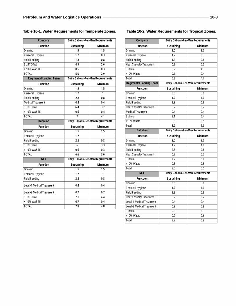
Petroleum and Water Logistics Operations __________________________________________________________________ 10-3
Table 10-1. Water Requirements for Temperate Zones. Table 10-2. Water Requirements for Tropical Zones.
Company Daily Gallons-Per-Man Requirements
Function Sustaining MinimumDrinking 1.5 1.5Personal Hygiene 1.7 0.3Field Feeding 1.3 0.8SUBTOTAL 4.5 2.6+ 10% WASTE 0.5 0.3TOTAL 5.0 2.9
Regimental Landing Team Daily Gallons-Per-Man Requirements
Function Sustaining MinimumDrinking 1.5 1.5Personal Hygiene 1.7 1Field Feeding 2.8 0.8Medical Treatment 0.4 0.4SUBTOTAL 6.4 3.7+ 10% WASTE 0.6 0.4TOTAL 7 4.1
Battalion Daily Gallons-Per-Man Requirements
Function Sustaining MinimumDrinking 1.5 1.5Personal Hygiene 1.7 1Field Feeding 2.8 0.8SUBTOTAL 6 3.3+ 10% WASTE 0.6 0.3TOTAL 6.6 3.6
MEF Daily Gallons-Per-Man Requirements
Function Sustaining MinimumDrinking 1.5 1.5Personal Hygiene 1.7 1Field Feeding 2.8 0.8
Level-1 Medical Treatment 0.4 0.4
Level-2 Medical Treatment 0.7 0.7SUBTOTAL 7.1 4.4+ 10% WASTE 0.7 0.4TOTAL 7.8 4.8
Company Daily Gallons-Per-Man Requirements
Function Sustaining MinimumDrinking 3.0 3.0Personal Hygiene 1.7 0.3Field Feeding 1.3 0.8Heat Casualty Treatment 0.2 0.2Subtotal 6.2 4.3+10% Waste 0.6 0.4Total 6.8 4.7Regimental Landing Team Daily Gallons-Per-Man Requirements
Function Sustaining MinimumDrinking 3.0 3.0Personal Hygiene 1.7 1.0Field Feeding 2.8 0.8Heat Casualty Treatment 0.2 0.2Medical Treatment 0.4 0.4Subtotal 8.1 5.4+10% Waste 0.8 0.5Total 8.9 5.9
Battalion Daily Gallons-Per-Man Requirements
Function Sustaining MinimumDrinking 3.0 3.0Personal Hygiene 1.7 1.0Field Feeding 2.8 0.8Heat Casualty Treatment 0.2 0.2Subtotal 7.7 5.0+10% Waste 0.8 0.5Total 8.5 5.5
MEF Daily Gallons-Per-Man Requirements
Function Sustaining MinimumDrinking 3.0 3.0Personal Hygiene 1.7 1.0Field Feeding 2.8 0.8Heat Casualty Treatment 0.2 0.2Level-1 Medical Treatment 0.4 0.4Level-2 Medical Treatment 0.9 0.9Subtotal 9.0 6.3+10% Waste 0.9 0.6Total 9.9 6.9
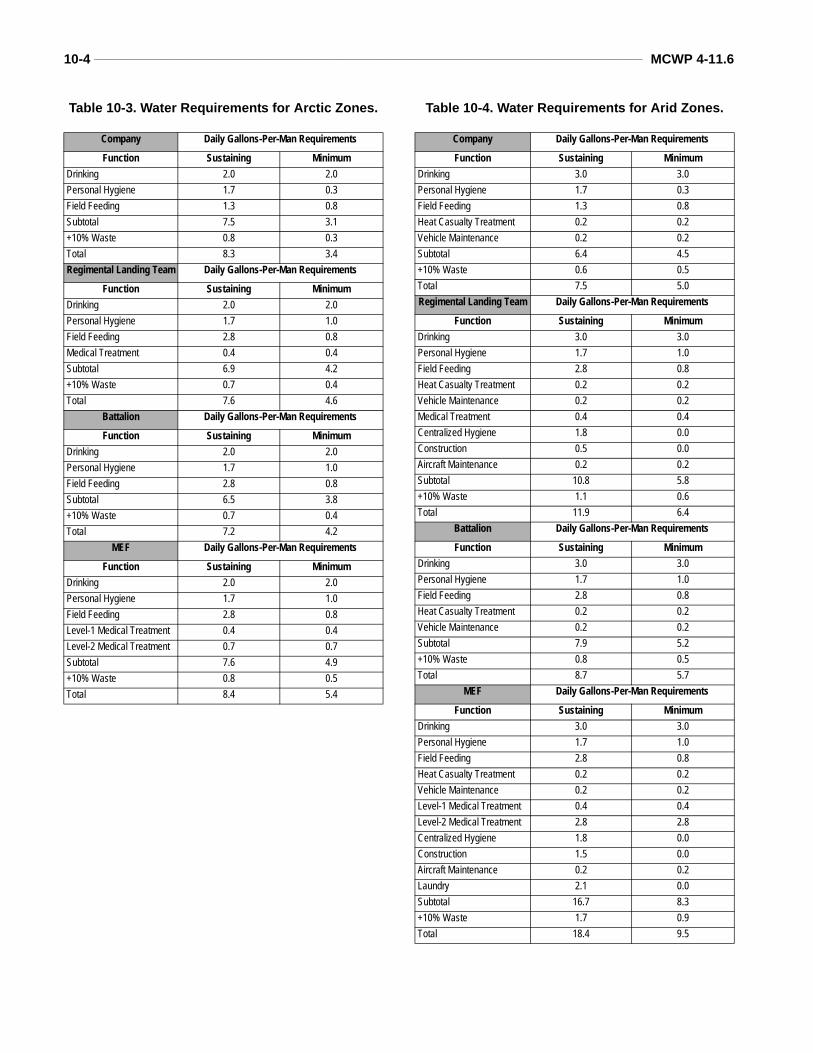
10-4 ___________________________________________________________________________________________________ MCWP 4-11.6
Table 10-3. Water Requirements for Arctic Zones. Table 10-4. Water Requirements for Arid Zones.
Company Daily Gallons-Per-Man Requirements
Function Sustaining MinimumDrinking 2.0 2.0Personal Hygiene 1.7 0.3Field Feeding 1.3 0.8Subtotal 7.5 3.1+10% Waste 0.8 0.3Total 8.3 3.4Regimental Landing Team Daily Gallons-Per-Man Requirements
Function Sustaining MinimumDrinking 2.0 2.0Personal Hygiene 1.7 1.0Field Feeding 2.8 0.8Medical Treatment 0.4 0.4Subtotal 6.9 4.2+10% Waste 0.7 0.4Total 7.6 4.6
Battalion Daily Gallons-Per-Man Requirements
Function Sustaining MinimumDrinking 2.0 2.0Personal Hygiene 1.7 1.0Field Feeding 2.8 0.8Subtotal 6.5 3.8+10% Waste 0.7 0.4Total 7.2 4.2
MEF Daily Gallons-Per-Man Requirements
Function Sustaining MinimumDrinking 2.0 2.0Personal Hygiene 1.7 1.0Field Feeding 2.8 0.8Level-1 Medical Treatment 0.4 0.4Level-2 Medical Treatment 0.7 0.7Subtotal 7.6 4.9+10% Waste 0.8 0.5Total 8.4 5.4
Company Daily Gallons-Per-Man Requirements
Function Sustaining MinimumDrinking 3.0 3.0Personal Hygiene 1.7 0.3Field Feeding 1.3 0.8Heat Casualty Treatment 0.2 0.2Vehicle Maintenance 0.2 0.2Subtotal 6.4 4.5+10% Waste 0.6 0.5Total 7.5 5.0Regimental Landing Team Daily Gallons-Per-Man Requirements
Function Sustaining MinimumDrinking 3.0 3.0Personal Hygiene 1.7 1.0Field Feeding 2.8 0.8Heat Casualty Treatment 0.2 0.2Vehicle Maintenance 0.2 0.2Medical Treatment 0.4 0.4Centralized Hygiene 1.8 0.0Construction 0.5 0.0Aircraft Maintenance 0.2 0.2Subtotal 10.8 5.8+10% Waste 1.1 0.6Total 11.9 6.4
Battalion Daily Gallons-Per-Man Requirements
Function Sustaining MinimumDrinking 3.0 3.0Personal Hygiene 1.7 1.0Field Feeding 2.8 0.8Heat Casualty Treatment 0.2 0.2Vehicle Maintenance 0.2 0.2Subtotal 7.9 5.2+10% Waste 0.8 0.5Total 8.7 5.7
MEF Daily Gallons-Per-Man Requirements
Function Sustaining MinimumDrinking 3.0 3.0Personal Hygiene 1.7 1.0Field Feeding 2.8 0.8Heat Casualty Treatment 0.2 0.2Vehicle Maintenance 0.2 0.2Level-1 Medical Treatment 0.4 0.4Level-2 Medical Treatment 2.8 2.8Centralized Hygiene 1.8 0.0Construction 1.5 0.0Aircraft Maintenance 0.2 0.2Laundry 2.1 0.0Subtotal 16.7 8.3+10% Waste 1.7 0.9Total 18.4 9.5
CHAPTER 11. WATER SUPPORT OPERATIONS
Effective water support is essential to missionaccomplishment. The water support mission isto get potable water to each Marine. Each Ser-vice is responsible for its own water support.However, the Army is the theater manager forwater support and may provide backup watersupport when the Services’ requirements exceedtheir capabilities. When a Service requiresbackup water support, the supported Servicemust provide detailed water requirements to theArmy planners. The Army will provide GSwater support to other Services in the theater asrequired. FM 10-52 provides detailed informa-tion on Army roles and responsibilities for watersupport in the theater. The theater army mate-rial management command monitors water pri-orities and allocation procedures and provide theJTF commander with water supply data. DuringJTF operations, the JTF commander may assignwater support responsibilities on an area basis.Under this “predominant user concept,” the pre-dominant Service in an area may be tasked toprovide water support to all Services operatingin that area above and beyond that Service’sorganic capabilities.
MAGTF Water Support Phases
MAGTFs may require water support for contin-gency operations in areas without a pre-estab-lished water support base to an operationinvolving allied/HN support. MAGTFs providewater support on an area basis using supply pointdistribution. Water support operations comprisethree phases—water purification, water storage,and water distribution.
Water Purification
Water purification is the first phase of water sup-port operations. During the purification phase,water is drawn from the source and purified topotable water standards. Potable water is certified
safe for human consumption. Water is purifiedwith a ROWPU, a medium freshwater purificationunit, or the TWPS. Standards are verified by amember of an environmental protection medicalunit or any corpsman with a water quality analysiskit and the knowledge of how to use it.
Water StorageWater storage is the second phase of water sup-port operations. Storage is normally done at orvery close to the purification sites. The goal ofwater storage is to keep 1 DOS on hand. This willprevent a water shortage if several purificationunits go down simultaneously. Storage can bedone using one (or a combination of) 500-galloncollapsible drum(s); SIXCON(s); 3,000-, 20,000-,and 50,000-gallon tanks.
Water DistributionThe third phase, water distribution, begins fromthe storage site. Water distribution is often thecritical link in water support operations. If thislink fails, the Marine goes thirsty. It is importantthat units organize so they will have sufficientorganic water distribution equipment to providesupply point distribution. During the early phasesof deployments and in emergency situations,packaged water will be the primary means ofresupply in forward areas. As the CSSEs areestablished and LOCs are developed, units willbegin pulling water from water points usingorganic 400-gallon water trailers and SIXCONwater modules.
MAGTF Water Support Responsibilities
Normally the water supply system is an auto-matic resupply operation. Generally, its onlylimitations are water availability and the capa-bility of receiving units. The forward movementof water is based on storage and distributionassets available.
11-2 ___________________________________________________________________________________________________ MCWP 4-11.6
MAGTF Command Element
The CE is responsible for overall water supportplanning and operations for the MAGTF. Whendemand exceeds supply, the MAGTF com-mander establishes an allocation system and sup-port procedures. The allocation system is basedon priorities to support the tactical plan.
To accomplish its mission, the CE performs thefollowing tasks:
Ensures water production, storage, and distri-bution is sufficient to support the entireMAGTF and any other water miss ionsassigned by the JTF commander.Submits required water data to the JTF or the-ater Army.Directs storage and distribution procedures andpriorities.Provides inventory management of GS watersupplies and sets allocations if required.Ensures economy of management of all watersupport equipment within the MAGTF.
Other MAGTF Elements
The other elements of the MAGTF (GCE, ACE,and CSSE) are responsible for planning, direct-ing, and supervising their organic water supportassets. Each element will ensure it has the capa-bilities to perform any water support taskingassigned by the MAGTF commander. Daily man-agement of the water points and water distribu-tion is the responsibility of the GCE, ACE, andCSSE. Water support requirements that arebeyond the organic capabilities of an element willbe addressed to the MAGTF CE for sourcing.Each MAGTF element has water purification,distribution, and storage capability. However, theCSSE has the preponderance of water supportequipment. As a result, the CSSE must be pre-pared to provide GS to the other elements of theMAGTF as needed.
Host Nation Considerations
HN water sources, facilities, and equipmentshould be used as much as possible. MAGTFwater planners should assume that no HN wateris available in arid regions. Minimal watersources and poor water quality may limit anyoperations that depend on HN support to meet thecriteria set forth in NAVMED P-5010-5 or TBMED 577 for water quality standards. In the earlystages of deployment, HN processed or bottledwater may be used if preventive medicine person-nel have certified it as potable. However, in bothdeveloped and undeveloped theaters, MAGTFcommanders and water planners must be aware ofthe following regulations.
WaterArticle 54 of the 1st Protocol to the GenevaConvention prohibits attacking, destroying, orrendering useless drinking water installationsand supplies and irrigation works. In no eventshall actions against these objects be takenwhich may be expected to leave the civilianpopulation with such inadequate food or wateras to cause its starvation or force its movement.
RefugeesArticle 55 of the 4th Geneva Convention statesthat the host country, as the territorial sovereign,is responsible for refugees on its territory. In theevent its resources are strained by an influx ofrefugees, the host country may request assistancefrom US forces. US forces would have a legalresponsibility to provide refugee care where theyhave occupied enemy territory and have estab-lished a military government.
Enemy Prisoners of WarArticle 26 of the 3d Geneva Convention requiresthe US to provide humane treatment to prisonersin its custody. This includes providing adequatewater and food.
Petroleum and Water Logistics Operations __________________________________________________________________ 11-3
Labor Force Personnel
The HN is responsible for filling the needs of itslabor forces unless otherwise provided in HNSagreements. In the absence of an agreement, USforces may have to assume some responsibilityfor the care of labor forces.
Regional Considerations
Arid Environment
Water sources are either nonexistent or extremelylimited in arid regions. The options available to theMAGTF will be limited to importing water, desali-nating seawater, or developing new water supplysources. Units will need to make maximum use oforganic water equipment for storage and distribu-tion. Water purification teams and detachmentswill often be required to operate from the shorepurifying saltwater with ROWPUs. The family ofwater supply support equipment is used to storeand distribute potable water to operating forces.Water moved forward is either stored in forwardwater supply points or issued to the using units.Water supply points are established as far forwardas possible, considering the location of watersources, the location of using units, and the tacti-cal plans. Based on resupply times and water avail-ability, MAGTF commanders will have toestablish the required DOS for water to be held ateach echelon. Operational and DS units will nor-mally maintain a minimum of 1 DOS.
Water supply operations in an arid environmentare typically conducted in three phases to ensureeffective and continual water support—develop-ment, lodgment, and buildup.
Development PhaseThis phase may begin as an air or amphibiousassault or as an uncontested entry at a friendlyport. The first MAGTF elements will probably be
combat forces with minimal CSS. Using canteens,5-gallon cans, and other organic equipment, theseforces carry only enough water for immediate sur-vival purposes. Resupply must begin quickly byeither air or from the sea. During this phase, pack-aged water will be primarily provided from off-shore or from the air from nontheater supportbases. Nonexpendable equipment used during thisphase, such as 500-gallon drums and 5-gallon cansmust be recovered and reused. MAGTF command-ers must exploit all water sources while keepingthe impact on the local population to a minimum.
Lodgment PhaseThe arrival of follow-on forces in the AO willincrease water requirements beyond the capa-bilities of aerial resupply except for forwarddeployed or isolated units. During this phase, incountry water support systems must be estab-lished. CSS units will provide purification, stor-age, and distribution of water in support of theMAGTF. CSS units will exploit any source ofwater in the AO using organic water purifica-tion equipment.
Buildup PhaseOnce the lodgment is established, expansion of thelogistics base begins. Additional water supportunits and equipment will arrive. The distributionsystem should be expanded to include tacticalwater distribution system whenever possible. Bulkwater can be introduced into the AOA via jointlogistics over-the-shore. Water points will beexpanded and moved as far forward as possible.
Nonarid Environment
Water support operations in an undeveloped,nonarid environment include development,lodgment, and buildup phases, and are identicalto those described in the arid environment.There are three distinct nonarid environmentsor regions: temperate, tropical, and arctic. See
11-4 ___________________________________________________________________________________________________ MCWP 4-11.6
chapter 10 for associated planning factors.Planning and operational considerations foreach are discussed below:
Temperate RegionsTemperate regions have seasonal variations thatmay affect water support operations such as hotsummers and cold winters. These variations mayhave a significant impact on where water pointsmay be located. In spring and fall, heavy rains mayflood streams and rivers. In the summer watersources may be low preventing sufficient waterflow for purification operations. These factorsrequire careful consideration by water plannersand coordination with meteorology and map/areareconnaissance when selecting water sites.
Tropical Regions
Water sources in tropical regions are often con-taminated with waterborne diseases and para-sites. Although an abundance of water may beavailable in a tropical region, purification andtreatment of raw water is required.
Arctic Regions
Water supply points in arctic regions must haveequipment to prevent or retard freezing. Equip-ment can include shelters and heaters. Watersources in arctic regions will present unusual prob-lems, including ground and source water freezingand distribution problems due to poor mobility.
Page number
CLASSIFICATION
APPENDIX APETROLEUM, OILS, AND LUBRICANTS APPENDIX
TO THE LOGISTICS ANNEXThe following is the format for the petroleum, oils, and lubricants (POL) appen-dix for combatant commander, JTF, and MAGTF OPLANs and OPORDs.
CLASSIFICATION
Copy No. _____ of _____ copiesOFFICIAL DESIGNATION OF COMMANDPLACE OF ISSUEDate/time groupMessage reference number
APPENDIX 1 TO ANNEX D TO OPLAN/PETROLEUM, OILS, AND LU-BRICANTS SUPPLY (U)
(U) REFERENCES: [List documents necessary for a complete understandingof this appendix; include current petroleum studies, joint agreements, and otherrelevant guidance as applicable.]
1. (U) General
a. (U) Purpose. State the purpose of this appendix.
b. (U) Users. Describe the concept of petroleum supply operations by des-ignating the users to be supported, including allied forces and civilian re-quirements, where applicable. Identify the agreements whereby support for the latter users would be undertaken.
2. (U) Concept of Operations
a. (U) Availability and suitability of commercial petroleum products, petro-leum storage, tanker unloading facilities, and petroleum distribution sys-tems, within the AO.
b. (U) Tanker offloading facilities and terminal facilities needed to meet US military requirements for petroleum support.
c. (U) Concept of inland distribution.
d. (U) Requirements for intertheater or intratheater movement of bulk pe-troleum to include points of origin, destination, type, and facilities available
A-2 ___________________________________________________________________________________________________ MCWP 4-11.6
Page number
CLASSIFICATION
CLASSIFICATION
or required to receive this type product. List POL data by product. Upon fielding of new time-phased force and deployment data format, the JOPES [Joint Operation Plan-ning and Execution System] produced listing will be used.
e. (U) Requirement for local procurement of commercial petroleum products and pe-troleum distribution and storage services within the AO.
f. (U) Establishment of a quality control activity within the AO.
3. (U) Responsibilities
a. (U) Assign specific tasks to military organizations, including the component com-manders, when appropriate.
b. (U) Delineate support responsibilities of the joint petroleum office, JTF, JTF component commanders, subarea petroleum offices, appropriate unified commands or their components, for the supply of petroleum, including responsibility for its transportation.
4. (U) Limiting Factors. Describe limitations that could adversely affect petroleum sup-ply operations, such as inadequate air and ocean terminal capacity, lack of storage facili-ties, malpositioned storage, inadequate transportation, inadequate in-theater stocks, lack of alternate facilities, and similar logistic constraints.
5. (U) Estimate of POL Support Requirements. Refer to TAB A, if applicable. Describe methodology used to compute requirements if Service planning factors were not applica-ble or if unique factors were considered.
ACKNOWLEDGE RECEIPT
NameRank and Service
Title
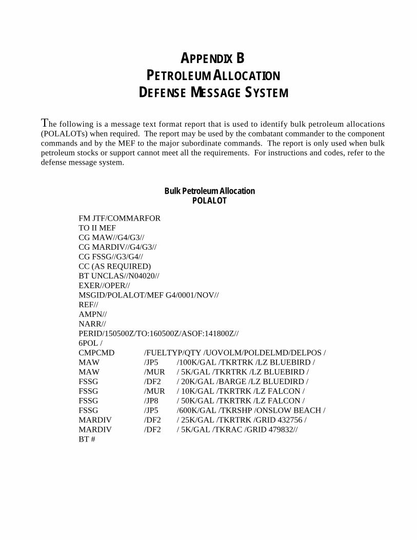
APPENDIX BPETROLEUM ALLOCATION
DEFENSE MESSAGE SYSTEM
The following is a message text format report that is used to identify bulk petroleum allocations(POLALOTs) when required. The report may be used by the combatant commander to the componentcommands and by the MEF to the major subordinate commands. The report is only used when bulkpetroleum stocks or support cannot meet all the requirements. For instructions and codes, refer to thedefense message system.
Bulk Petroleum AllocationPOLALOT
FM JTF/COMMARFORTO II MEF CG MAW//G4/G3// CG MARDIV//G4/G3// CG FSSG//G3/G4//CC (AS REQUIRED)BT UNCLAS//N04020//EXER//OPER//MSGID/POLALOT/MEF G4/0001/NOV//REF//AMPN//NARR//PERID/150500Z/TO:160500Z/ASOF:141800Z//6POL /CMPCMD /FUELTYP/QTY /UOVOLM/POLDELMD/DELPOS /MAW /JP5 /100K/GAL /TKRTRK /LZ BLUEBIRD /MAW /MUR / 5K/GAL /TKRTRK /LZ BLUEBIRD /FSSG /DF2 / 20K/GAL /BARGE /LZ BLUEDIRD /FSSG /MUR / 10K/GAL /TKRTRK /LZ FALCON /FSSG /JP8 / 50K/GAL /TKRTRK /LZ FALCON /FSSG /JP5 /600K/GAL /TKRSHP /ONSLOW BEACH /MARDIV /DF2 / 25K/GAL /TKRTRK /GRID 432756 /MARDIV /DF2 / 5K/GAL /TKRAC /GRID 479832//BT #
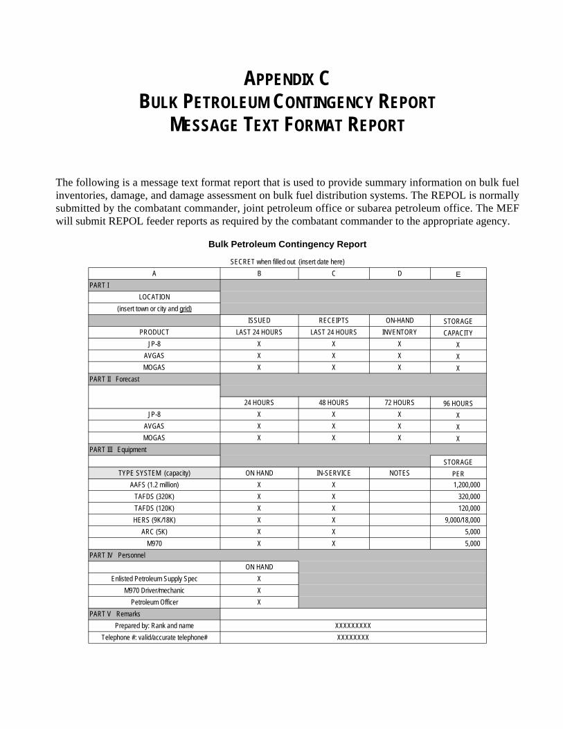
APPENDIX CBULK PETROLEUM CONTINGENCY REPORT
MESSAGE TEXT FORMAT REPORT
The following is a message text format report that is used to provide summary information on bulk fuelinventories, damage, and damage assessment on bulk fuel distribution systems. The REPOL is normallysubmitted by the combatant commander, joint petroleum office or subarea petroleum office. The MEFwill submit REPOL feeder reports as required by the combatant commander to the appropriate agency.
Bulk Petroleum Contingency Report
SECRET when filled out (insert date here)A B C D E
PART I LOCATION
(insert town or city and grid)ISSUED RECEIPTS ON-HAND STORAGE
PRODUCT LAST 24 HOURS LAST 24 HOURS INVENTORY CAPACITYJP-8 X X X X
AVGAS X X X XMOGAS X X X X
PART II Forecast
24 HOURS 48 HOURS 72 HOURS 96 HOURSJP-8 X X X X
AVGAS X X X XMOGAS X X X X
PART III EquipmentSTORAGE
TYPE SYSTEM (capacity) ON HAND IN-SERVICE NOTES PERAAFS (1.2 million) X X 1,200,000
TAFDS (320K) X X 320,000TAFDS (120K) X X 120,000HERS (9K/18K) X X 9,000/18,000
ARC (5K) X X 5,000M970 X X 5,000
PART IV PersonnelON HAND
Enlisted Petroleum Supply Spec XM970 Driver/mechanic X
Petroleum Officer XPART V Remarks
Prepared by: Rank and name XXXXXXXXXTelephone #: valid/accurate telephone# XXXXXXXX
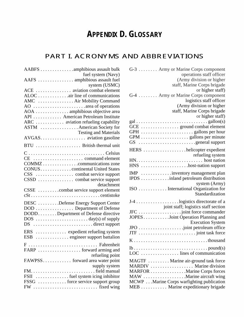
APPENDIX D. GLOSSARY
PART I. ACRONYMS AND ABBREVIATIONS
AABFS . . . . . . . . . . . . . .amphibious assault bulkfuel system (Navy)
AAFS . . . . . . . . . . . . . . . amphibious assault fuelsystem (USMC)
ACE . . . . . . . . . . . . . . . aviation combat elementALOC . . . . . . . . . . . . .air line of communicationsAMC . . . . . . . . . . . . . . . Air Mobility CommandAO . . . . . . . . . . . . . . . . . . . . . .area of operationsAOA . . . . . . . . . . . . . . amphibious objective areaAPI . . . . . . . . . . . . American Petroleum InstituteARC . . . . . . . . . . . . aviation refueling capabilityASTM . . . . . . . . . . . . . . . . American Society for
Testing and MaterialsAVGAS. . . . . . . . . . . . . . . . . . . aviation gasolineBTU . . . . . . . . . . . . . . . . . . . British thermal unitC . . . . . . . . . . . . . . . . . . . . . . . . . . . . . . . . CelsiusCE . . . . . . . . . . . . . . . . . . . . . command elementCOMMZ . . . . . . . . . . . . . . .communications zoneCONUS. . . . . . . . . . . . . continental United StatesCSS . . . . . . . . . . . . . . . . combat service supportCSSD . . . . . . . . . . . . . . . combat service support
detachmentCSSE . . . . . . . . .combat service support elementcSt . . . . . . . . . . . . . . . . . . . . . . . . . . . . . centistokeDESC . . . . . . . . .Defense Energy Support CenterDOD . . . . . . . . . . . . . . . . Department of DefenseDODD. . . . . . . . Department of Defense directiveDOS . . . . . . . . . . . . . . . . . . . . . . day(s) of supplyDS . . . . . . . . . . . . . . . . . . . . . . . . . direct supportERS . . . . . . . . . . . . . expedient refueling systemESB . . . . . . . . . . . . . . engineer support battalionF . . . . . . . . . . . . . . . . . . . . . . . . . . . . . FahrenheitFARP . . . . . . . . . . . . . . . . . . forward arming and
refueling pointFAWPSS. . . . . . . . . . . . forward area water point
supply systemFM. . . . . . . . . . . . . . . . . . . . . . . . . . . field manualFSII . . . . . . . . . . . . . . fuel system icing inhibitorFSSG . . . . . . . . . . . . force service support groupFW . . . . . . . . . . . . . . . . . . . . . . . . . . . fixed wing
G-3 . . . . . . . . Army or Marine Corps componentoperations staff officer
(Army division or higherstaff, Marine Corps brigade
or higher staff)G-4 . . . . . . . . Army or Marine Corps component
logistics staff officer(Army division or higher
staff, Marine Corps brigadeor higher staff)
gal . . . . . . . . . . . . . . . . . . . . . . . . . . . . . . gallon(s)GCE . . . . . . . . . . . . . . . . ground combat elementGPH . . . . . . . . . . . . . . . . . . . . . . gallons per hourGPM . . . . . . . . . . . . . . . . . . . . gallons per minuteGS . . . . . . . . . . . . . . . . . . . . . . . .general supportHERS . . . . . . . . . . . . . . . . . . helicopter expedient
refueling systemHN. . . . . . . . . . . . . . . . . . . . . . . . . . . . host nationHNS . . . . . . . . . . . . . . . . . . . .host-nation supportIMP . . . . . . . . . . . . . inventory management planIPDS . . . . . . . . . . . . inland petroleum distribution
system (Army)ISO . . . . . . . . . . . . International Organization for
StandardizationJ-4 . . . . . . . . . . . . . . . . . . logistics directorate of a
joint staff; logistics staff sectionJFC . . . . . . . . . . . . . . . . . . joint force commanderJOPES . . . . . . . . . . .Joint Operation Planning and
Execution SystemJPO . . . . . . . . . . . . . . . . . . .joint petroleum officeJTF . . . . . . . . . . . . . . . . . . . . . . . . joint task forceK . . . . . . . . . . . . . . . . . . . . . . . . . . . . . . . thousandlb . . . . . . . . . . . . . . . . . . . . . . . . . . . . . . . pound(s)LOC . . . . . . . . . . . . . . . . lines of communicationMAGTF . . . . . . . . . Marine air-ground task forceMARDIV . . . . . . . . . . . . . . . . . . Marine divisionMARFOR . . . . . . . . . . . . . . .Marine Corps forcesMAW . . . . . . . . . . . . . . . . . .Marine aircraft wingMCWP . . .Marine Corps warfighting publicationMEB . . . . . . . . . . . Marine expeditionary brigade
D-2 ___________________________________________________________________________________________________ MCWP 4-11.6
MEF . . . . . . . . . . . . . Marine expeditionary forceMEU . . . . . . . . . . . . . . Marine expeditionary unitMIL-DTL . . . . . . . . . military detail specificationMIL-STD . . . . . . . . . . . . . . . . . military standardMOGAS . . . . . . . . . . . . . . . . . . . . motor gasolineMOS . . . . . . . . . . military occupational specialtyMPS . . . . . . . . . . . . maritime prepositioning shipMPSRON . . . . . . . . . . . .maritime prepositioning
ships squadronMWSG . . . . . . . . . . . Marine wing support groupMWSS. . . . . . . . . Marine wing support squadron
NATO . . . . . .North Atlantic Treaty OrganizationNAVAIR. . . . . . . . Naval Air Systems CommandNAVMED. . . . . . . . . . . Navy Medical CommandNBC . . . . . . . . . . . . . . . . nuclear, biological, and
chemicalNOLSC . . . . . . . . . Naval Operational Logistics
Support CenterNSN . . . . . . . . . . . . . . . . National Stock Number
OPDS . . . . . . . . . . .offshore petroleum dischargesystem (Navy)
OPLAN . . . . . . . . . . . . . . . . . . . . . .operation planPOL . . . . . . . . . . . petroleum, oils, and lubricantsPOLALOT . . . . . . . . . . . . . .petroleum allocationpsi . . . . . . . . . . . . . . . . . . .pounds per square inchPWRR . . . . . petroleum war reserve requirementPWRS . . . . . . . . . . petroleum war reserve stocks
REPOL . . . . . . . . . . . . . . . . . . . . . bulk petroleumcontingency report
ROWPU . . . . . . . . . . . . . . reverse osmosis waterpurification unit
RW . . . . . . . . . . . . . . . . . . . . . . . . . . . rotary wing
S-3. . . . . . . . . . . . .battalion or brigade operationsstaff officer (Army;
Marine Corps battalionor regiment)
S-4. . . . . . . . . . . . . . battalion or brigade logisticsstaff officer (Army;
Marine Corps battalionor regiment)
SAPO . . . . . . . . . . . . . . subarea petroleum officeSIPRNET . . . . . . . . . . . . Secret Internet Protocol
Router NetworkSIXCON . . . . . . . . . . . . . . six containers togetherSOA . . . . . . . . . . . . . sustained operations ashoreSOP . . . . . . . . . . . . . standing operating procedureSTS . . . . . . . . . . . . . . . . . . . . . . . . . . ship to shore
TAFDS . . . . . . . . . . . . . . . . . tactical airfield fueldispensing system
TAMCN . . . . . . . . . . table of authorized materielcontrol number
TBFDS . . . . . . . . . . . . . . . . . . . .tactical bulk fueldistribution system
TB MED . . . . . . . . . . . technical bulletin, medicalTFS . . . . . . . . . . . . . . . . . . . . tactical fuel systemsTPLM . . . . . . . . . . tactical petroleum laboratory,
mediumTWDS . . . . . . . .tactical water distribution systemTWPS . . . . . . . tactical water purification system
US . . . . . . . . . . . . . . . . . . . . . . . . . . United StatesUSAPC . . . . . . . . . . . US Army Petroleum CenterUSMC . . . . . . . . . . . . United States Marine Corps
WQAS-P . . . . . . . . . . . . . . .water quality analysisset-purification
WSSE . . . . . . . . water supply support equipment
PART II. DEFINITIONS
additive—An agent used for improving existingcharacteristics or for giving new characteristics tocertain petroleum products. (FM 10-67)
aerial refueling—The use of aerial tanker-configured aircraft to provide refueling service tohelicopters, fixed-wing, and tilt-rotor aircraft inflight. Aerial refueling extends the range, time on
station, mobility, and flexibility of MAGTFaircraft. (MCRP 5-12C)
American Petroleum Institute—The instituterepresents and is supported by the petroleumindustry. It standardizes the tools and equipmentused by the industry and promotes the advance-ment of research in the petroleum field. Alsocalled API. (FM 10-67-1)
Petroleum and Water Logistics Operations ___________________________________________________________________ D-3
American Society for Testing and Materi-als—A national scientific and technical organi-zation formed for the development of standardsor characteristics and performance of materials,products, systems, and services and the promo-tion of related knowledge. Also called ASTM.
amphibious assault bulk fuel system—The USNavy system of flexible, buoyant hose used toeffect ship-to-shore transfer of fuels. Five thou-sand feet of 6-inch hose connects amphibiousshipping to shorebased fuel storage systemslocated at the high water mark. Also calledAABFS. (MCRP 5-12C)
amphibious assault fuel system—The MarineCorps’ primary fuel storage system used tosupport amphibious operations. This system iscomposed of a number of components capable ofreceiving, transferring, and dispensing motorgasoline, diesel, or aviation fuels. The system canbe set up in a wide variety of configurations tomeet varying operational requirements. Alsocalled AAFS. (MCRP 5-12C)
amphibious objective area—A geographicalarea (delineated for command and controlpurposes in the order initiating the amphibiousoperation) within which is located the objec-tive(s) to be secured by the amphibious force.This area must be of sufficient size to ensureaccomplishment of the amphibious force’smission and must provide sufficient area forconducting necessary sea, air, and land opera-tions. Also called AOA. (JP 1-02)
API gravity—An arbitrary scale expressing thegravity or density of liquid petroleum products.The measuring scale is calibrated in terms ofdegrees API. The gravity of any petroleum prod-uct is corrected to 60 degrees F (16 degrees C).(FM 10-67-1)
appearance—Refers to the visual examination offuels. The terms used to describe appearance areclear and bright, hazy and cloudy. (FM 10-67-1)
barrel—A common unit of measurement ofliquids in the petroleum industry. It equals 42 USstandard gallons. (FM 10-67)
berm—An earthen wall constructed around afuel tank to contain potential fuel leaks or spills.
berm liner—A cloth or plastic tarp, imperviousto fuel, used to line a berm.
blending—Mixing on-specification fuel withoff specification fuel to bring the latter to spec-ification or use limits. Used as a method ofreclamation.
bonding—Making an electrical connectionbetween items of equipment/tanks. Bondingequalizes electrical potential between items, andreduces the threat of sparks due to static electric-ity passing between the items of equipment.
bottom sediment and water—Amount of sedi-ment and water in the bottom of fuel tanks.
bulk fuel company—A unit that performs allfunctions incident to the supply of class III andclass III(A) to elements of a MAGTF, to includedistribution to, but not within, air bases during anamphibious assault and subsequent operationsashore; to ensure that class III(A) productsdistributed to supported air elements are of therequired type, quality, and purity. (MCRP 5-12C)
bulk liquid—Fuel or water itself, not inclusive ofthe container or handling apparatus. A term alsoused to define quantities of fuel or water aboveeither 55 gallons or 250/500 gallons; the formerwhen handling product in 55-gallon metal drumsis common, the latter when 250/500-gallon
D-4 ___________________________________________________________________________________________________ MCWP 4-11.6
collapsible water drums or 500-gallon collaps-ible fuel drums are in use.
bulk petroleum products—Those petroleumproducts (fuels, lubricants) which are normallytransported by pipeline, rail tank car, tank truck,barge, or tanker and stored in tanks or containershaving a capacity of more than 55 gallons, exceptfuels in 500-gallon collapsible containers, whichare considered to be packaged. (FM 10-67)
carbon dioxide—A heavy, colorless gas, CO2,that will not support combustion (therefore, usefulas a fire-extinguishing agent). (FM 10-67-1)
carbon monoxide—A colorless, odorless, andpoisonous gas, CO, resulting from the incom-plete combustion of carbon. (FM 10-67-1)
centrifuge—A whirling instrument for separat-ing liquids or liquids and solids of differentspecific gravity by use of centrifugal force. (FM10-67)
Class III—Petroleum products; petroleum, oilsand lubricants often broken down into Class IIIAfor aviation fuel, and Class III(W) for groundequipment fuel.
combat service support detachment—A sepa-rate task organization of combat service supportassets formed for the purpose of providing rearm-ing, refueling, and/or repair capabilities to theMarine air-ground task force or designated subor-dinate elements; e.g., a battalion conducting inde-pendent operations or an aircraft squadronoperating at a remote airfield. The combat servicesupport element normally provides the commandelement of a combat service support detachment.Also called CSSD. (MCRP 5-12C)
contaminant—A foreign substance in a product.(FM 10-67-1)
Defense Energy Support Center—An activityunder the Defense Logistics Agency with theresponsibility as the integrated material manager
for wholesale bulk petroleum products until theirdelivery to the point of sale. This responsibilityincludes contract administration in an overseearea. Also called DESC. (FM 10-70-1)
defense fuel supply point—Any military orcommercial bulk fuel terminal storing productsowned by the Defense Logistics Agency. Alsocalled DFSP. (FM 10-67-1)
Defense Logistics Agency—The agency, at theDepartment of Defense level, charged with provid-ing the most effective and economical support ofcommon supplies and services to the MilitaryDepartments and other designated Department ofDefense components. It is the agency under whichDefense Energy Support Center operates. Alsocalled DLA. (FM 10-67-1)
drum—Either 16- or 18-gage steel cylindricalcontainers (generally, 55-gallon size) or 250/500-gallon collapsible water containers/500-galloncollapsible fuel containers.
flashpoint—The temperature at which a fuel will“flash” when exposed to test flame flame diame-ter of approximately 1/8 inch, like a butanelighter flame adjusted as low as possible; also atest performed per the American Society for Test-ing and Materials.
force service support group—The combatservice support element of the Marine expedition-ary force. It is a permanently organized FleetMarine Force command charged with providingcombat service support beyond the organic capa-bilities of supported units of the Marine expedi-tionary force. If supporting a force of greater size,additional assets are necessary to augment itscapabilities. Although permanently structuredwith eight functional battalions, task organiza-tions from those battalions would normallysupport Marine expeditionary force operationsover a wide geographic area. Also called FSSG.(MCRP 5-12C)
Petroleum and Water Logistics Operations ___________________________________________________________________ D-5
forward arming and refueling point—A tempo-rary facility—organized, equipped, and deployedby an aviation commander, and normally locatedin the main battle area closer to the area of opera-tion than the aviation unit’s combat service area—to provide fuel and ammunition necessary for theemployment of aviation maneuver units in combat.The forward arming and refueling point permitscombat aircraft to rapidly refuel and rearm simul-taneously. Also called FARP. (JP 1-02)
gallon—A unit of measure of volume. A USgallon contains 231 cubic inches or 3.785 liters; itis 0.83268 times the imperial gallon. One USgallon of water weighs 8.3374 pounds at 60degrees F (16 degrees C). (FM 10-67-1)
ground cloth—A protective cloth placed beneathcollapsible bulk liquid tanks to protect the bottomof the tank from sharp objects.
grounding—Electrically connecting single orbonded units to a ground rod so static potential isdischarged into the earth.
halon—Halogenated hydrocarbon fuel fire extin-guishing agent. It comes in various chemicalcomposition models; Halon 1211, Halon 1301, etc.
inventory—Bulk tankage contents measured tocurrent product level; includes tank bottoms andassociated pipeline fill. (FM 10-67-1)
joint petroleum office—An office established bythe Joint Chiefs of Staff with petroleum logisticsresponsibilities in a unified command in overseasareas. (FM 10-67-1)
petroleum—Crude oil. Petroleum is a mixture ofgaseous, liquid, and semisolids hydrocarbonsvarying widely in gravity and complexity. Petro-leum can be removed as a liquid from under-ground reservoirs, and it can be separated intovarious fractions by distillation and recovery.Petroleum is a general term that includes all
petroleum fuels, lubricants, and specialties. (FM10-67-1)
rear operations—Military actions conducted tosupport and permit force sustainment and toprovide security for such actions. (MCRP 5-12C)
reverse osmosis—The application of pressure toa concentrated solution which causes the passageof a liquid from the concentrated solution to aweaker solut ion across a semipermeablemembrane. The membrane allows the passage ofthe solvent (water) but not the dissolved solids(solutes). The liquid produced is a demineralizedwater. (FM 10-70-1; FM 10-52)
sortie—In air operations, an operational flight byone aircraft. (JP 1-02)
specification—Prescribed limits of control testsused to maintain uniformity of a specific prod-uct. (FM 10-67-1)
storage capacity—Total of existing bulk tankageassigned for product storage. Capacity is measuredto maximum fill level for each tank and includesnonrecoverable tank bottoms. (FM 10-67-1)
subarea petroleum office—A sub-office of aJPO established by the JPO to fulfill petroleumlogistics responsibilities in a section of thegeographical area for which the JPO is responsi-ble. Also called SAPO. (FM 10-67-1)
tactical airfield fuel dispensing system—Anexpeditionary system providing bulk fuel storageand dispensing facilities at airfields not havingpermanently installed fuel systems; also used tosupport fuel dispensing at established airfields.Also called TAFDS. (MCRP 5-12C)
tank—A storage container for liquid products.
tanker—A seagoing vessel for transportingliquids. Coastal tankers have less draft (depth of aship below the waterline) than oceangoing tank-ers. (FM 10-67-1)
D-6 ___________________________________________________________________________________________________ MCWP 4-11.6
terminal—A bulk facility for receipt, storage,transportation, and issue of petroleum products.The facility may be a base terminal for receiptand shipment of product by tanker, a pipeheadterminal (head terminal) at the downstream endof the pipeline, or an intermediate terminal onthe pipeline. The terminal consists of a tankfarm or tank farm complex, tank farm manifold,and central pump station area. (FM 10-67-1)
total dissolved solids—All of the dissolvedsolids in a water. Total dissolved solids aremeasured on a sample of water that has passedthrough a very fine mesh fil ter to removesuspended solids. The water passing through thefilter evaporated and the residue represents thedissolved solids. (FM 10-52)
ullage—The amount by which a container, stor-age tank, or storage facility falls short of being full.
volume correction—The correction of measuredquantity of product, determined by gauging atobserved temperature and gravity and referenceto a gage table, to net quantity of product at 60degrees F (16 degrees C) after deducting bottomwater and sediment. (FM 10-67-1)
water—An odorless, colorless, transparent liquid,solid (ice), or gas (steam), compound H2O.
water, dissolved—All fuel contains some waterin solution, and amounts will vary with tempera-ture. This type water is not separated from fuel byfilter separators or other mechanical means.
water, entrained—“Free” water which issuspended throughout a fuel (or sample) and hasnot yet settled to the bottom of fuel container/tank.
APPENDIX E. REFERENCES
Department of Defense Directives (DODDs)
4140.25 DOD Management Policy for Energy Commodities and Related Services
5101.8 DOD Executive Agent (EA) for Bulk Petroleum
Department of Defense Military Specification (MILSPEC)
DTL-5624T Turbine Fuel, Aviation, Grades JP-4 and JP-5DTL-83133E Turbine Fuel, Aviation, Grade JP-8G-5572 Gasoline, Aviation, Grades 80/87, 100/130,
115/145A-A-52557 Fuel oil, Diesel; for Posts, Camps and StationsMIL-F-16884 Fuel, Navy Distillate
Chairman of the Joint Chiefs of Staff Manual (CJCSM)
3122.03A Joint Operation Planning and Execution System(JOPES), Volume II, Planning Formats and Guidance
Department of Defense Military Standard (MIL-STD)
3004-A Quality Surveillance for Fuels, Lubricants, andRelated Products
Department of Defense (DOD) Publication
4140.25-M DOD Management of Bulk Petroleum Products,Natural Gas, and Coal (Volumes I-IV)
4715.5G Overseas Environmental Baseline Guidance Document
Joint Publication (JP)
4-03 Joint Bulk Petroleum and Water Doctrine
Naval Air Systems Command (NAVAIR) Publication
00-80T-109 Aircraft Refueling Naval Air Training and Operating Procedures Standardization(NATOPS) Manual
E-2 ____________________________________________________________________________________________________ MCWP 4-11.6
Navy Medical Command (NAVMED) Publication
P-5010-5 Preventive Medicine Manual (Chapter 5, WaterSupply Ashore)
Marine Corps Doctrinal Publication (MCDP)
4 Logistics
Marine Corps Warfighting Publications (MCWPs)
3-17 Engineer Operations4-1 Logistics Operations4-11.7 MAGTF Supply Operations
Marine Corps Order (MCO)
P5090.2A Environmental Compliance and Protection Manual
Air Force Technical Order (AF TO)
42 Security System Data
Army Field Manuals (FMs)
10-52 Water Supply in Theaters of Operations10-52-1 Water Supply Point Equipment and Operations
Army Technical Bulletin, Medical (TB MED)
577 Occupational and Environmental Health: Sanitary Control and Surveillance ofField Water Supplies
American Society for Testing and Materials (ASTM) Specifications
D-3240-91 (2001) Standard Test Method for Undissolved Waterin Aviation Turbine Fuels
D-1655-04 Standard Specification for Aviation Turbine Fuels
D-4814 Standard Specifications for Automotive Spark-Ignition Engine Fuel