MCS-8 HEAT PUMP MANUAL FH… · Heatpump Water-Air/Water-Water Heatpump/Chillers MCS-8 Version 7...
44
MCS-8 HEAT PUMP MANUAL Version 7 Revision 4.0 Software HPMP 7.00-U and greater Supports MCS-STAT The MCS Commitment Our commitment is to provide practical solutions for the industries needs and to be both a leader and partner in the effective use of microprocessor controls. Micro Control Systems, Inc. 5400-1 Division Drive Fort Myers, Florida 33905 (239) 694-0089 FAX: (239) 694-0031 www.mcscontrols.com Information contained in this manual has been prepared by Micro Control Systems, Inc. and is company confidential and copyright © protected 1996. Copying or distributing this document is prohibited.
Transcript of MCS-8 HEAT PUMP MANUAL FH… · Heatpump Water-Air/Water-Water Heatpump/Chillers MCS-8 Version 7...

MCS-8 HEAT PUMP MANUAL
Version 7 Revision 4.0
Software HPMP 7.00-U and greater
Supports MCS-STAT
The MCS Commitment Our commitment is to provide practical solutions for the industries needs and to be both a leader and partner in the effective use of microprocessor controls.
Micro Control Systems, Inc. 5400-1 Division Drive
Fort Myers, Florida 33905 (239) 694-0089
FAX: (239) 694-0031 www.mcscontrols.com
Information contained in this manual has been prepared by Micro Control Systems, Inc. and is company confidential and copyright © protected 1996. Copying or distributing this document is prohibited.

Heatpump Water-Air/Water-Water Heatpump/Chillers MCS-8 Version 7 Manual Revision 4.0
1 Revision Page Date Author Description of Changes
9/4/97 Kelly Mitchell Draft 5/1/98 Kelly Mitchell Updated manual for release version 1.0 5/12/98 R C Toney Update for Empire State Bldg. changes version1.1 7/15/98 R C Toney Minor corrections to the v1.1, control state summary and flow
diagram of the heat pump was added, changed to version 1.2 10/21/98 J G Walterick V7 update to generic, SI8/16, rearrange setpoints, new setpoints
8/28/00 Brian Walterick Revisions to make manuals for both heatpumps and chillers-Labeled the manual Revision 2.0
02/02/01 Brian Walterick Updated manual for Modulating Hot Water Valve Heating Control
02/02/01 Brian Walterick Updated manual for Modulating Economizer Valve Control
07/15/02 R C Toney Updated manual reflects the new set points required for control zone control. Cutin/cutout no longer supported. Software FHP 07.00-S and greater support changes. Manual labeled as Revision 2.2
7/28/03 SAK Updating Manual
09/10/04 RCT Communicating thermostat and all of its functions are now supported in HPMP 7.00-U and greater software. The reheat function has been separated from the heat function. PC-Config 32 bit version 1.69 or greater is required to support these new functions.
09/24/04 RCT Added a modulating reheat function. PC-Config 32 bit version 1.70or greater is required to support these new functions.
2

Heatpump Water-Air/Water-Water Heatpump/Chillers MCS-8 Version 7 Manual Revision 4.0
2 Table of Contents 1 Revision Page .......................................................................................................................................2
2 Table of Contents .................................................................................................................................3
3 Introduction to the MCS-8 Heatpump / Chiller Controller ..................................................................6
3.1 The MCS-8 Micro Controller:.....................................................................................................6
3.2 The MCS-8 will control the following items: .............................................................................7
3.3 Control will be based upon the following: ..................................................................................7
4 Introduction to Control Modes and States............................................................................................8
4.1 CONTROL MODES...................................................................................................................8 4.1.1 FAN/PUMP ONLY MODE..................................................................................................................................8 4.1.2 COOLING MODE...............................................................................................................................................8 4.1.3 HEATING MODE................................................................................................................................................9 4.1.4 DEHUMIDIFICATION MODE............................................................................................................................9 4.2 CONTROL STATES ..................................................................................................................9
4.3 CONTROL STATUS DISPLAY (from the MCS-8 keypad) ...................................................10
4.4 CONTROL STATUS DISPLAY (from the PC-Conn Program) ..............................................10
5 MCS-STAT Support...........................................................................................................................12
5.1.1 Wiring from the MCS-8.....................................................................................................................................12 5.1.2 Temperature sensor. ........................................................................................................................................12 5.1.3 Humidity sensor ................................................................................................................................................12 5.1.4 LCD Display ......................................................................................................................................................12 5.1.5 LCD Alarms.......................................................................................................................................................12 5.1.6 Fan switch .........................................................................................................................................................14 5.1.7 Off/AUTO/SCHEDULED switch ......................................................................................................................14 5.1.8 Override button .................................................................................................................................................14
6 Heatpump / Chiller Control States: ....................................................................................................15
5.1 BASE STATES.........................................................................................................................15 6.1.1 ‘HEATPUMP OFF’ state- .................................................................................................................................15 6.1.2 ‘FAN/PUMP ONLY’ state- (FAN/PUMP ONLY Control Mode)......................................................................15 6.2 COOLING’ states – (COOLING Control Mode) .....................................................................15 6.2.1 ECONO COOLING ..........................................................................................................................................16 6.2.2 COOL: 1 COMP................................................................................................................................................16 6.2.3 COOL: 2 COMPS.............................................................................................................................................16 6.2.4 COOL: 3 COMPS.............................................................................................................................................16
3
Heatpump Water-Air/Water-Water Heatpump/Chillers MCS-8 Version 7 Manual Revision 4.0
6.2.5 COOL: 4 COMPS.............................................................................................................................................17 6.3 HEATING’ states - (HEATING Control Mode).......................................................................17 6.3.1 ECON HEATING..............................................................................................................................................17 6.4 HEATING’ states - (type of heat is REVERSING VALVE) ...................................................18 6.4.1 HEAT: 1 COMP (type of heat is REVERSING VALVE).................................................................................18 6.4.2 HEAT: 2 COMPS (type of heat is REVERSING VALVE) ..............................................................................18 6.4.3 HEAT: 3 COMPS (type of heat is REVERSING VALVE) ..............................................................................18 6.4.4 HEAT: 4 COMPS (type of heat is REVERSING VALVE) ..............................................................................19 6.5 HEATING’ states - (type of heat is HOT WATER VALVE) ..................................................19 6.5.1 HEAT-HOLDING (type of heat is HOT WATER VALVE) ..............................................................................19 6.5.2 HEAT-CLOSING (type of heat is HOT WATER VALVE)...............................................................................19 6.5.3 HEAT-OPENING (type of heat is HOT WATER VALVE) ..............................................................................19 6.5.4 HEAT-SLOPE CL (type of heat is HOT WATER VALVE) .............................................................................19 6.5.5 HEAT-SLOPE OP (type of heat is HOT WATER VALVE).............................................................................19 6.6 HEATING’ states - (type of heat is ELECTRIC HEAT)..........................................................20 6.6.1 ELECTRIC HEAT (type of heat is ELECTRIC HEAT) ...................................................................................20 6.7 DEHUMID states – (DEHUMIDIFICATION Control Mode) .................................................20 6.7.1 DEHUM: 1 COMP ............................................................................................................................................20 6.7.2 DEHUM: 2 COMPS..........................................................................................................................................21 6.7.3 DEHUM: 3 COMPS..........................................................................................................................................21 6.7.4 DEHUM: 4 COMPS..........................................................................................................................................21
7 Reheat Options ...................................................................................................................................23
7.1 None ..........................................................................................................................................23
7.2 Hot Gas Reheat..........................................................................................................................23
7.3 Modulating Reheat only in dehumidification states..................................................................23
7.4 Electric Reheat ..........................................................................................................................23
7.5 Modulating Reheat in all states except HEATPUMP OFF or lock off states ...........................23
8 MCS-8 States for Heatpump / Chiller Faults .....................................................................................25
8.1 LOCKOUT FAULT..................................................................................................................25
8.2 SAFETY FAULT......................................................................................................................25
8.3 SENSOR FAULT......................................................................................................................25
9 ECONOMIZER STATES ..................................................................................................................26
9.1 BYPASSED-COOL ..................................................................................................................26
7.2 BYPASSED-HEAT ..................................................................................................................26
7.3 ECONO OFF.............................................................................................................................26
4

Heatpump Water-Air/Water-Water Heatpump/Chillers MCS-8 Version 7 Manual Revision 4.0
9.4 ECONO COOL ON ..................................................................................................................26
9.5 ECONO HEAT ON...................................................................................................................26
9.6 NOT USED ...............................................................................................................................26
10 SET POINTS AND DEFINITIONS: .................................................................................................27
11 Return Air Target Reset Logic ...........................................................................................................32
12 AUTHORIZATION FUNCTION......................................................................................................33
13 The Micro Control Center Keypad Display Quick Reference ...........................................................34
14 The Micro Control Center Keypad Display Quick Reference-ENTRY KEYS....................................35
15 The Micro Control Center MCS-8 Quick Reference Sheet ...............................................................36
16 Details of MCS-8 Key Items ..............................................................................................................37
17 Details of MCS-SI8/16 Key Items .....................................................................................................38
18 The MCS Sensors Quick Reference Sheet – Temperature, Supply Air, Humidity & Pressure transducers .................................................................................................................................................39
19 The MCS Sensors Quick Reference Sheet - Dry Contact Inputs .......................................................40
20 The MCS Trouble Shooting Quick Reference Sheet .........................................................................41
21 Summary of Control States ................................................................................................................43
5
Heatpump Water-Air/Water-Water Heatpump/Chillers MCS-8 Version 7 Manual Revision 4.0
3 Introduction to the MCS-8 Heatpump / Chiller Controller
3.1 The MCS-8 Micro Controller:
The MCS-8 micro controller is designed to be the primary controller for a heatpump / chiller package. The MCS-8 control algorithm provides the ultimate in control strategies by enabling:
• The user to custom the controlling sensors in each of the four different modes, • Establish targets and control zones that can be modified after a package has been commissioned, • Eliminate service calls by:
• Take corrective action to prevent an alarm condition from occurring, and • Automatically restarting a package following an alarm condition and not locking the package off
unless the same alarm has occurred twice with in a settable time period. • Provide an easy to understand man-machine-interface by:
• Indicating the state of the system in English terms and • Identifying in English terms all alarms and date/time stamping them.
The system design is modular and allows for one, two, three or four compressors. This is accomplished by coupling an MCS-8 with either MCS I/O, RO-8 or SI-8 or SI-16 boards that provides the additional inputs that is required. The system provides for:
• Optional economy stage for heating and or cooling, • Complete dehumidification control and • Standard heating and cooling control.
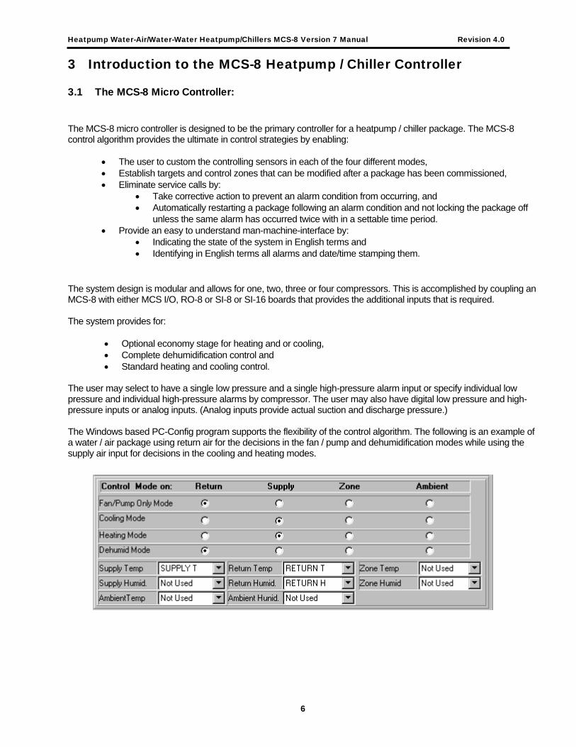
The user may select to have a single low pressure and a single high-pressure alarm input or specify individual low pressure and individual high-pressure alarms by compressor. The user may also have digital low pressure and high-pressure inputs or analog inputs. (Analog inputs provide actual suction and discharge pressure.) The Windows based PC-Config program supports the flexibility of the control algorithm. The following is an example of a water / air package using return air for the decisions in the fan / pump and dehumidification modes while using the supply air input for decisions in the cooling and heating modes.
6

Heatpump Water-Air/Water-Water Heatpump/Chillers MCS-8 Version 7 Manual Revision 4.0
The following is an example of a package using zone air for all decisions. The zone temperature and humidity input can be provided by MCS-STAT, communicating thermostat.
For additional flexibility the MCS-STAT is now supported with this software. This enables communication via the MCS-STAT to be provided in the zone area.
3.2 The MCS-8 will control the following items:
• Blower motor(s) or pumps, (on/off plus speed control) • Ball valve that directs flow through the economizer coil, • Heatpump / chiller reversing valve(s), • Compressors (up to 4), • Hot gas reheat, • Electric heating, • Modulating reheat, • Hot water heating and • Alarm indicator.
3.3 Control will be based upon the following:
• Internal time clock that is battery backed up; • Internal set points that can be adjusted with the proper authorization in a commissioned unit; • Condenser water in & condenser water out; • Return, Supply, Zone or Ambient air temperature; • Return, Supply, Zone or Ambient air humidity; • Run enable switch (digital input from the building management system), Network Run enable, or Run
enable from a MCS-STAT, communicating thermostat; • System schedule override from the MCS-STAT, this is based upon the time in setpoint #20 when the
override button on the MCS-STAT is pushed and the system is not in an alarm mode. • A series of safety indicators (some will require manual intervention while others will result in an automatic
restart when the condition is corrected).
7

Heatpump Water-Air/Water-Water Heatpump/Chillers MCS-8 Version 7 Manual Revision 4.0
4 Introduction to Control Modes and States
4.1 CONTROL MODES
The Control Mode dictates the general status of the unit and which Control States can be entered. There are four modes and each mode has a unique control sensor and set points that are associated with that mode.
4.1.1 FAN/PUMP ONLY MODE
The FAN/PUMP ONLY STATE indicates this mode. It is in this mode that the system determines if any of the other three modes should be entered. The other three modes; cooling, heating or dehumidification; will be entered based upon set points 1 through 3: COOL ENABLE, HEAT ENABLE AND DEHD ENABLE. Once the system is in one of the other three modes, its requirements must be satisfied and control returned to the fan/pump only mode before any of the other modes can be entered. In the example shown, the Return Air Sensor is the controlling sensor in this mode. If the Return Air is greater than the cooling set point, the system will enter the Cooling Mode.
4.1.2 COOLING MODE
Once in this mode the system will develop a control-cooling zone based upon set points 4, 5 & 6. The system will move through the cooling states to maintain the temperature within this control zone. Once the cooling target has been satisfied, the system will return to the FAN/PUMP ONLY MODE. In the example shown, the Supply Air Sensor is the controlling sensor in this mode. The system will step up and down through all of the cooling states based upon the supply air temperature. Once the supply air cool temperature target has been satisfied, the system will return to the FAN/PUMP ONLY MODE.
• Contro l C o n tro l Zo n e +
Ta rget
C o n tro l Zo n e-
8

Heatpump Water-Air/Water-Water Heatpump/Chillers MCS-8 Version 7 Manual Revision 4.0
4.1.3 HEATING MODE
Once in this mode the system will develop a control-heating zone based upon set points 10, 11 & 12. The system will move through the heating states to maintain the temperature within this control zone. Once the heating target has been satisfied, the system will return to the FAN/PUMP ONLY MODE. The system will support three different types of heating: 1. Reversing Valve. The reversing valve will be turned on when in the heating mode and the compressors will be staged on/off to maintain the temperature within the control-heating zone. 2. Hot Water Valve. The hot water valve will be modulated when in the heating mode to maintain the temperature within the control-heating zone. Set points 46 through 54 will control the modulation of the valve. 3. Electric Heat. The relay output for the electric heat will be turned on when the control temperature is below the control-heating zone. There can be only one stage of electric heat. In the example shown, the Supply Air Sensor is the controlling sensor in this mode. The system will step up and down through all of the heating states based upon the supply air temperature. Once the supply air heat temperature target has been satisfied, the system will return to the FAN/PUMP ONLY MODE.
4.1.4 DEHUMIDIFICATION MODE
Once in this mode the system will develop a control dehumidification zone based upon set points 16, 17 & 18. The control air will be cooled and reheated to dry out the air. The system will move through the dehumidification states to maintain the humidity within this control zone. Once the humidity target has been satisfied, the system will turn off the reheat and either return to the FAN/PUMP ONLY MODE if the control temperature does not require cooling or to the first stage of cooling. The reheat function is now specified independently from the heat options, refer to the section on reheat.
The Heat Type is Electric Heat, its associated RO is EL HEAT and the Reheat Type is Hot Gas its associated RO is HGreheat.
In this mode the system is also checking to ensure that air temperature remains in the range created by the values contained in set points #40,ALLOW DEHUMD, and #41, DISALW DHDIFF. If the temperature is not with in this range, the system will immediately return to the FAN/PUMP ONLY MODE for further action. Note the temperature sensor that is being checked is specified as the controlling sensor in the FAN/PUMP ONLY MODE.
The set points values that are associated with each mode must be set based upon the control sensor that is used with each mode.
4.2 CONTROL STATES
The MCS-8 controller is a state computer, that is, decisions are made based upon set points, timers and sensor inputs, the controller moves from one state to another. The controller will change states to ensure the proper functioning of the heatpump / chiller package. Control States perform the following:
9

Heatpump Water-Air/Water-Water Heatpump/Chillers MCS-8 Version 7 Manual Revision 4.0
• Provides an easy to understand status of the system. For example, HEATPUMP OFF state indicates that
the system is off or the COOL: 1 COMP states indicates that the system is in the cooling mode and that compressor 1 is on and providing cooling.
• Dictates, which relays (RO’S) will be on in a given state.
• Indicates how long the system has been in the current state.
• The system moves from one state to another in a fixed sequence with fixed rules. This strategy is based upon providing target set points for heating, cooling and dehumidification. The system then controls the heatpump / chiller capacity to maintain the target temperature. Set points that contain differential values are used to calculate a control zone and the system will determine if more or less cooling, heating or dehumidification capacity is needed to remain in this control zone. The control states are divided into the following two groups:
• HEAT PUMP / CHILLER CONTROL STATES, these states deal with the status of the heat pump / chiller system. They will indicate if the system is running and what action is being taken.
• ECONOMIZER CONTROL STATES, these states deal with the status of the economizer valve. Control states, on the MCS-8, are displayed on the 2x16 LCD by depressing the SERVICE DIAGNOSTICS entry key and then selecting the option CONTROL STATUS. (Depress the enter key.) The up and down arrow may then used to scroll between the information screens. The control states can also be accessed via the PC-Conn program by selecting ‘STATUS’ from the button bar on the ‘SYS INF’ screen.
4.3 CONTROL STATUS DISPLAY (from the MCS-8 keypad)
The following will be displayed: The FIRST SCREEN will display the HEAT PUMP / CHILLER CONTROL STATE and the time in that state. Line 1) Line 2) (time HH:MM:SS)
COOL: 2 COMPS TIMER 1:26:06
The SECOND SCREEN will display by selecting with either the INCREASE or DECREASE key. This screen will display the ECONOMIZER CONTROL STATE and the time in that state. Line 1) Line 2) (time HH:MM:SS)
ECON COOLING TIMER 1:28:06
4.4 CONTROL STATUS DISPLAY (from the PC-Conn Program)
The status of both the HEAT PUMP / CHILLER STATES and ECONOMIZER STATES can also be viewed from the PC-Conn program by accessing the STATUS button; in the lower right section of the status screen. The following will be displayed:
10

Heatpump Water-Air/Water-Water Heatpump/Chillers MCS-8 Version 7 Manual Revision 4.0
11

Heatpump Water-Air/Water-Water Heatpump/Chillers MCS-8 Version 7 Manual Revision 4.0
5 MCS-STAT Support One MCS-STAT is support in this software. It must be associated with the zone options.
5.1.1 Wiring from the MCS-8.
Communications between the MCS-8 and the communicating thermostat is provided via a four wire shielded cable. This will provide the power and the RS485 communications. Two wires provide communications by connecting the MCS I/O connector to the MCS-STAT. Make sure that the + terminal on the MCS-8 is connected to the + on the MCS-STAT. The MCS-STAT requires 12 volts, this can be provided by connecting the other two wires to the +12 volt and ground terminals on the MCS-8 and the MCS-STAT.
5.1.2 Temperature sensor.
• This is a temperature sensor with accuracy of ± 0.1°F between 32°F and 99°F; it will provide the zone temperature.
• This sensor display type must be STAT1F in the SI Info screen for the PC-Config. • If used this must be in selected in the HT Pmp Info screen as the zone temperature.
5.1.3 Humidity sensor
• This is a humidity sensor with accuracy of ± 0.2% between 0% and 100%; it will provide the zone humidity. • This sensor display type must be STAT1% in the SI Info screen for the PC-Config. • If used this must be in selected in the HT Pmp Info screen as the zone humidity.
5.1.4 LCD Display
• If the indicator is pointing to: Actual: either the temperature which will be followed by an °F, e.g. 73.4°F, or the humidity, e.g. 45.7, will be displayed. Either the up or down arrows will toggle between these two values. Cool: The value of setpoint #4, COOL TARGET, will be displayed. This value can be changed with the up and down arrows within the minimum and maximum range that is set for this setpoint. When the SET button is pressed the new value will be transmitted to the MCS-8. Heat: The value of setpoint #10, HEAT TARGET, will be displayed. This value can be changed with the up and down arrows within the minimum and maximum range that is set for this setpoint. When the SET button is pressed the new value will be transmitted to the MCS-8.
• If a alarm is active, an alarm number will be displayed on the MCS-STAT to indicate the alarm reason.
5.1.5 LCD Alarms
ALARM NAME DESCRIPTION # Displayed INVALID CFG The configuration of the MCS-8 is
invalid or wrong type. The system will not run.
1
INVALID CLOCK The hardware clock on the MCS-8 has failed. Processing will continue using the software clock.
2
LOST MCS I/O An MCS I/O board is not communicating.
3
MCS I/O OFF LINE An MCS I/O board has gone off line.
4
EVAP OVRFLW1 An overflow on evaporator #1 has occurred. Refer to setpoint #30.
5
12
Heatpump Water-Air/Water-Water Heatpump/Chillers MCS-8 Version 7 Manual Revision 4.0
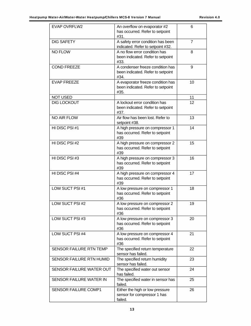
EVAP OVRFLW2 An overflow on evaporator #2 has occurred. Refer to setpoint #31.
6
DIG SAFETY A safety error condition has been indicated. Refer to setpoint #32.
7
NO FLOW A no flow error condition has been indicated. Refer to setpoint #33.
8
COND FREEZE A condenser freeze condition has been indicated. Refer to setpoint #34.
9
EVAP FREEZE A evaporator freeze condition has been indicated. Refer to setpoint #35.
10
NOT USED 11 DIG LOCKOUT A lockout error condition has
been indicated. Refer to setpoint #37.
12
NO AIR FLOW Air flow has been lost. Refer to setpoint #38.
13
HI DISC PSI #1 A high pressure on compressor 1 has occurred. Refer to setpoint #39
14
HI DISC PSI #2 A high pressure on compressor 2 has occurred. Refer to setpoint #39
15
HI DISC PSI #3 A high pressure on compressor 3 has occurred. Refer to setpoint #39
16
HI DISC PSI #4 A high pressure on compressor 4 has occurred. Refer to setpoint #39
17
LOW SUCT PSI #1 A low pressure on compressor 1 has occurred. Refer to setpoint #36
18
LOW SUCT PSI #2 A low pressure on compressor 2 has occurred. Refer to setpoint #36
19
LOW SUCT PSI #3 A low pressure on compressor 3 has occurred. Refer to setpoint #36
20
LOW SUCT PSI #4 A low pressure on compressor 4 has occurred. Refer to setpoint #36
21
SENSOR FAILURE RTN TEMP The specified return temperature sensor has failed.
22
SENSOR FAILURE RTN HUMID The specified return humidity sensor has failed.
23
SENSOR FAILURE WATER OUT The specified water out sensor has failed.
24
SENSOR FAILURE WATER IN The specified water in sensor has failed.
25
SENSOR FAILURE COMP1 Either the high or low pressure sensor for compressor 1 has failed.
26
13

Heatpump Water-Air/Water-Water Heatpump/Chillers MCS-8 Version 7 Manual Revision 4.0
SENSOR FAILURE COMP2 Either the high or low pressure sensor for compressor 2 has failed.
27
SENSOR FAILURE COMP3 Either the high or low pressure sensor for compressor 3 has failed.
28
SENSOR FAILURE COMP4 Either the high or low pressure sensor for compressor 4 has failed.
29
NOT USED 30 NOT USED 31
5.1.6 Fan switch
• The fan switch indicates if the fan is to be on continuously, ON position or AUTO the system will control the fan status.
• If used this sensor display type must be STAT1FN in the SI Info screen for the PC-Config.
5.1.7 Off/AUTO/SCHEDULED switch
• This switch indicates if the unit is in an off, auto or schedule mode. OFF: will force the system to be off. This is in affect another run/stop switch to the MCS-8. AUTO: will override the operating schedule making it always true. SCHD: will allow the system to follow the operating schedule that is setup in the MCS-8.
• This sensor display type must be STAT1SY in the SI Info screen for the PC-Config.
5.1.8 Override button
• The override button performs the following functions: If an alarm has occurred, the MCS-STAT horn will be on and the alarm light will be flashing. - The first time that the button is pushed, the horn will be turned off but the alarm light will remain flashing. - The second time that the button is pushed, the alarm light go off and a lockout reset message will be transmitted to the MCS-8. This will perform the same action as if the lockout reset button on the MCS-8 was pushed. If the system has no active alarms and the override button is pushed and the MCS-8 has the system off due to the schedule being false; the schedule will be overridden for the time specified in setpoint #20. The system will be enabled to run for this amount of time.
14

Heatpump Water-Air/Water-Water Heatpump/Chillers MCS-8 Version 7 Manual Revision 4.0
6 Heatpump / Chiller Control States: The MCS-8 control algorithm will move from one state to another based upon set points, timers and sensor inputs. The states and set points are defined in this document. The sophisticated control algorithm allows the controller to decide on the number of heating, cooling or dehumidification stages based on one sensor while FAN/PUMP ONLY stage can be controlled based on the same or a different sensor. (For instance: In the fan/pump mode the decision to cool, heat or dehumidify could be based on return air while in the control of cooling and or heating modes the decision could be based on supply air.) Refer to the section on CONTROL MODE. The system will develop cooling, heating and dehumidification control zones and move through the various states to maintain the control air temperature or humidity within those control zones.
5.1 BASE STATES
At startup the system will be in off state and when temperature and humidity conditions have been satisfied the system will be in fan/pump only state.
6.1.1 ‘HEATPUMP OFF’ state-
When the system is powered up it will delay going into the normal operating mode based on the ‘STARTUP DLY’ set point. This state will also be entered if the RUN/STOP or NETWORK RUN/STOP switch is set to STOP or the MCS-STAT system switch is set to OFF. Or if the RUN/STOP or NETWORK RUN/STOP switch is set to RUN and the MCS-STAT system switch is set to SCHD and the operating schedule is false. Once the startup delay time has expired the system and the system is enabled to run, the next state, FAN/PUMP ONLY state, will be entered.
6.1.2 ‘FAN/PUMP ONLY’ state- (FAN/PUMP ONLY Control Mode)
When the system exits the HEATPUMP OFF state it will enter the FAN/PUMP ONLY state if either the operating schedule is true or the RUN/STOP input is in run mode. (The RUN/STOP input is from a user input, usually the building management system.) From this state the decision is made to go to heating, cooling, dehumidification or stay in the ‘FAN/PUMP ONLY’ state based on its controlling sensor. Examples of the set points for the ‘FAN/PUMP ONLY’ state are shown below. These are based on using return air as the controlling sensor. ‘FAN/PUMP ONLY’ state –
Set Point # 1 ‘COOL ENABLE’ 75.0F Set Point # 2 ‘HEAT ENABLE’ 68.0F Set Point # 3 ‘DEHD ENABLE’ 55.0%
6.2 COOLING’ states – (COOLING Control Mode)
These states are entered from the ‘FAN/PUMP ONLY’ state. Examples of the set points for the COOLING state are shown below, based on using supply air as the controlling sensor. Cooling mode –
Set Point # 4 ‘COOL TARGET’ 50.0F Set Point # 5 ‘COOL ZONE+’ 5.0F Set Point # 6 ‘COOL ZONE- ’ - 5.0F
A cooling zone will be developed based upon the COOL TARGET and the COOL ZONE+ and the COOL ZONE- set points. The system will add or remove cooling stages as needed to maintain the temperature within the control cooling zone.
15

Heatpump Water-Air/Water-Water Heatpump/Chillers MCS-8 Version 7 Manual Revision 4.0
6.2.1 ECONO COOLING
This state is the economize mode and it will be entered if the controlling air temperature rises above the COOL TARGET set point and the water temperature is below the COOL’G WATER set point. The valve that directs the water flow will remain open in all cooling states as long as the water temperature is below the COOL’G WATER set point. The ECONOMIZER STATES indicate the status of this valve. In this state:
• The blower motor(s) is on. • The valve that directs the water flow is open if the entering water is below the cold-water set point.
This state will be exited and the FAN ONLY state will be entered once the controlling air temperature has been satisfied. If additional cooling is required, the system will move to the COMPRESSOR 1 COOLING stage. The system will remain in the ECONO COOLING state for a minimum time as specified in the STEP DELAY set point unless the water temperature is too warm to provide cooling, the system will immediately move to the COMP1 COOLING state.
6.2.2 COOL: 1 COMP
This state is the first stage of mechanical cooling and it will be entered if the controlling air temperature rises above this stage’s set point. In this state:
• The blower motor(s) is on. • The valve that directs the water flow is open if the water temperature is below the cool water set point. • The reversing valve is on (cool state). • Compressor one is turned on.
Once the controlling air temperature has been satisfied the ECONO COOLING state will be entered. If additional cooling is required the system will move to COOL: 2 COMP. The system will remain in the COOL: 1 COMP state for a minimum time as specified in the STEP DELAY set point.
6.2.3 COOL: 2 COMPS
This state is the second stage of mechanical cooling and it will be entered if an additional stage of cooling is needed to keep the controlling air temperature within the control cool zone. In this state:
• The blower motor(s) is on. • The valve that directs the water flow is open if the water temperature is below the cool water set point. • The reversing valve is on (cool state). • Compressor one is turned on. • Compressor two is turned on.
Once the controlling air temperature has been satisfied the COOL: 1 COMP state will be entered. If additional cooling is required the system will move to COOL: 3 COMP. The system will remain in the COOL: 2 COMP state for a minimum time as specified in the STEP DELAY set point.
6.2.4 COOL: 3 COMPS
This state is the third stage of mechanical cooling and it will be entered if an additional stage of cooling is needed to keep the controlling air temperature within the control cool zone. In this state:
• The blower motor(s) is on. • The valve that directs the water flow is open if the water temperature is below the cool water set point. • The reversing valve is on (cool state). • Compressor one is turned on. • Compressor two is turned on. • Compressor three is turned on.
16
Heatpump Water-Air/Water-Water Heatpump/Chillers MCS-8 Version 7 Manual Revision 4.0
Once the controlling air temperature has been satisfied the COOL: 2 COMP state will be entered. If additional cooling is required the system will move to COOL: 4 COMP. The system will remain in the COOL: 3 COMP state for a minimum time as specified in the STEP DELAY set point.
6.2.5 COOL: 4 COMPS
This state is the fourth stage and final stage of mechanical cooling and it will be entered if an additional stage of cooling is needed to keep the controlling air temperature within the control cool zone. In this state:
• The blower motor(s) is on. • The valve that directs the water flow is open if the water temperature is below the cool water set point. • The reversing valve is on (cool state). • Compressor one is turned on. • Compressor two is turned on. • Compressor three is turned on. • Compressor four is turned on.
Once the controlling air temperature has been satisfied the COOL: 3 COMP state will be entered. The system will remain in the COOL: 4 COMP state for a minimum time as specified in the STEP DELAY set point.
6.3 HEATING’ states - (HEATING Control Mode)
These states are entered from the ‘FAN/PUMP ONLY’ state. Examples of the set points for the HEATING state are shown below based on using supply air as the controlling sensor. Heating mode –
Set Point # 10 ‘HEAT TARGET’ 70.0F Set Point # 11 ‘HEAT ZONE+’ 1.0F Set Point # 12 ‘HEAT ZONE-‘ -1.0F
A heating zone will be developed based upon the HEAT TARGET and the HEAT ZONE+ and the HEAT ZONE- set points. The system will add or remove heating stages if type of heating is reversing valve or if hot water the system will modulate the valve as needed to maintain the temperature within the control heating zone. If the heating type is electric, the system will turn on the electric heat relay when the temperature is below the control heating zone.
6.3.1 ECON HEATING
This state is the economize heating and it will be entered if the controlling air temperature falls below this stage’s set point and the water temperature is above the HEAT’G WATER set point. The valve that directs the water flow will remain open in all heating states as long as the water temperature is above the HEAT’G WATER set point. The ECONOMIZER STATES indicate the status of this valve. In this state:
• The blower motor(s) is on. • The valve that directs the water flow is open, if the entering water is above the heating water set
point. Economize heating is if available will be utilized by all three types of heating. This state will be exited and the fan/pump only mode will be entered once the air temperature has been satisfied. The system will remain in the ECONO HEATING state for a minimum time as specified in the STEP DELAY set point unless the water temperature is too cool to provide heating and the controlling air temperature is calling for additional heating.
17

Heatpump Water-Air/Water-Water Heatpump/Chillers MCS-8 Version 7 Manual Revision 4.0
6.4 HEATING’ states - (type of heat is REVERSING VALVE)
When the type of heat utilizes the reversing valve, the system will stage the compressors to maintain the control temperature with in the control heat zone.
6.4.1 HEAT: 1 COMP (type of heat is REVERSING VALVE)
This state is the first stage of mechanical heating and it will be entered if the controlling air temperature falls below this stage’s set point. In this state:
• The blower motor(s) is on. • The valve that directs the water flow is open if the water temperature is above the heating water set
point. • The reversing valve is off (heat state). • Compressor one is turned on.
Once the controlling air temperature has been satisfied the system will move to the ECONO HEATING mode. If additional heating is required, the system will move to the HEAT: 2 COMPS state. The system will remain in the HEAT: 1 COMP state for a minimum time as specified in the STEP DELAY set point.
6.4.2 HEAT: 2 COMPS (type of heat is REVERSING VALVE)
This state is the second stage of mechanical heating and it will be entered if an additional stage of heating is needed to keep the controlling air temperature within the control heat zone. In this state:
• The blower motor(s) is on. • The valve that directs the water flow is open if the water temperature is above the heating water set
point. • The reversing valve is off (heat state). • Compressor one is turned on. • Compressor two is turned on.
Once the controlling air temperature has been satisfied the system will move to the HEAT: 1 COMP mode. If additional heating is required, the system will move to the HEAT: 1 COMPS state. The system will remain in the HEAT: 2 COMPS state for a minimum time as specified in the STEP DELAY set point.
6.4.3 HEAT: 3 COMPS (type of heat is REVERSING VALVE)
This state is the third stage of mechanical heating and it will be entered if an additional stage of heating is needed to keep the controlling air temperature within the control heat zone. In this state:
• The blower motor(s) is on. • The valve that directs the water flow is open if the water temperature is above the heating water set
point. • The reversing valve is off (heat state). • Compressor one is turned on. • Compressor two is turned on. • Compressor three is turned on.
Once the controlling air temperature has been satisfied the system will move to the COMP2 HEATING mode. If additional heating is required, the system will move to the COMP4 HEATING state. The system will remain in the COMP3 HEATING state for a minimum time as specified in the STEP DELAY set point.
18

Heatpump Water-Air/Water-Water Heatpump/Chillers MCS-8 Version 7 Manual Revision 4.0
6.4.4 HEAT: 4 COMPS (type of heat is REVERSING VALVE)
This state is the fourth and final stage of mechanical heating and it will be entered if an additional stage of heating is needed to keep the controlling air temperature within the control heat zone. In this state:
• The blower motor(s) is on. • The valve that directs the water flow is open if the water temperature is above the heating water set
point. • The reversing valve is off (heat state). • Compressor one is turned on. • Compressor two is turned on. • Compressor three is turned on. • Compressor four is turned on.
Once the controlling air temperature has been satisfied the system will move to the HEAT: 3 COMPS mode. The system will remain in the HEAT: 4 COMPS state for a minimum time as specified in the STEP DELAY set point.
6.5 HEATING’ states - (type of heat is HOT WATER VALVE)
When the type of heat utilizes hot water, the system will modulate the hot water valve to maintain the control temperature with in the control heat zone. The system determines if the control temperature is within, above or below the control zone and the control temperatures rate of change. Based upon this information the system determines if the hot water valve should be modulated and by what percentage. Refer to set points 46 through 54.
6.5.1 HEAT-HOLDING (type of heat is HOT WATER VALVE)
No change will be made to the hot water valve opening. The control temperature is being maintained.
6.5.2 HEAT-CLOSING (type of heat is HOT WATER VALVE)
The system will reduce the valve’s opening percentage. The control temperature is above the control zone and the control temperature is not falling faster than allowed, based upon set point 53, HW MAX ROC-. If the valve is completely closed, the system will move the to the FAN/PUMP ONLY state.
6.5.3 HEAT-OPENING (type of heat is HOT WATER VALVE)
The system will increase the valve’s opening percentage. The control temperature is below the control zone and the control temperature is not increasing at a fast enough rate. The amount that the valve will be opened by will be calculated based upon where the temperature is in relationship to the heat target.
6.5.4 HEAT-SLOPE CL (type of heat is HOT WATER VALVE)
The system will reduce the valve’s opening percentage. The control temperature is moving toward the heat target too fast. If the control temperature is within the control zone, the valve percentage open will be reduced by the value in set point 48, HW MIN ADJ%. If the temperature is outside of the control zone, the amount that the valve will be closed by will be calculated based upon where the temperature is in relationship to the heat target.
6.5.5 HEAT-SLOPE OP (type of heat is HOT WATER VALVE)
The system will increase the valve’s opening percentage. The control temperature is moving is not moving toward the heat target. If the control temperature is within the control zone, the valve percentage open will be increased by the value in set point 48, HW MIN ADJ%. If the temperature is outside of the control zone, the amount that the valve will be opened by will be calculated based upon where the temperature is in relationship to the heat target.
19

Heatpump Water-Air/Water-Water Heatpump/Chillers MCS-8 Version 7 Manual Revision 4.0
6.6 HEATING’ states - (type of heat is ELECTRIC HEAT)
If type of heating is electric, this is only one stage of heating. It is either on if heat is required or off.
6.6.1 ELECTRIC HEAT (type of heat is ELECTRIC HEAT)
The system will turn on the electric heat when the control temperature is below the control heat zone. The electric heat will remain on until the control temperature is above the control heat zone.
6.7 DEHUMID states – (DEHUMIDIFICATION Control Mode)
These states are entered from the ‘FAN/PUMP ONLY’ state. Examples of the set points for the DEHUMID state are shown below based on using return air as the controlling sensor. Dehumidification mode – Set Point # 16 ‘DEHD TARGET’ 55.0% Set Point # 17 ‘DEHUM ZONE+’ 5.0% Set Point # 18 ‘DEHUM ZONE- ‘ -5.0% A dehumidification zone will be developed based upon the DEHD TARGET and the DEHUM ZONE+ and the DEHUM ZONE- set points. The system will add or remove dehumidification stages as needed to maintain the humidity within the control dehumidification zone.
REFER TO THE REHEAT OPTIONS SECTION. Note: The ECONO COOLING is enabled during dehumidification if the water temperature is below the ECON CL ON set point #28. The valve that directs the water flow will remain open in all dehumidification stages as long as the water temperature remains below this set point
6.7.1 DEHUM: 1 COMP
This state can only be entered if the system is in the FAN/PUMP ONLY state. This state is entered when the controlling air humidity (usually return or zone humidity) rises above the control dehumidification zone and the controlling air temperature is below the allow dehumidification set point. If the controlling air temperature is above the cooling setpoint the system will enter COOLING. (COOLING has priority since we want to take out moisture but don’t want the reheat on.) In this state:
• The blower motor(s) is on. • The valve that directs the water flow is open if the water temperature is below the cool water set
point. • The reversing valve is on (cool state). • Compressor one is turned on. • Enable reheat.
When the controlling air humidity drops below the control dehumidification zone or the controlling air temperature is above the disallow dehumidification set point calculation, the system will return to the FAN/PUMP ONLY state. The system will remain in the DEHUM: 1 COMP state for a minimum time as specified in the STEP DELAY set point unless the controlling air temperature is above the disallow dehumidification set point calculation.
20

Heatpump Water-Air/Water-Water Heatpump/Chillers MCS-8 Version 7 Manual Revision 4.0
6.7.2 DEHUM: 2 COMPS
This state is the second stage of mechanical dehumidification and it will be entered if an additional stage of dehumidification is needed to keep the controlling air humidity within the control dehumidification zone. In this state:
• The blower motor(s) is on. • The valve that directs the water flow is open if the water temperature is below the cool water set
point. • The reversing valve is on (cool state). • Compressor one is turned on. • Enable reheat. • Compressor two is turned on.
If the controlling air temperature is above the disallowed dehumidification set point calculation, the system will immediately return to the FAN/PUMP ONLY state. If the system determines that this stage is no longer needed to keep the humidity within the control dehumidification zone, Compressor two will be turned off and the system will return to the DEHUM: 1 COMP state. The system will remain in the DEHUM: 2 COMP state for a minimum time as specified in the STEP DELAY set point unless the controlling air temperature is above the disallow dehumidification set point calculation.
6.7.3 DEHUM: 3 COMPS
This state is the third stage of mechanical dehumidification and it will be entered if an additional stage of dehumidification is needed to keep the controlling air humidity within the control dehumidification zone. In this state:
• The blower motor(s) is on. • The valve that directs the water flow is open if the water temperature is below the cool water set
point. • The reversing valve is on (cool state). • Compressor one is turned on. • Enable reheat. • Compressor two is turned on. • Compressor three is turned on.
If the controlling air temperature is above the disallowed dehumidification set point calculation, the system will immediately return to the FAN ONLY state. If the system determines that this stage is no longer needed to keep the humidity within the control dehumidification zone, Compressor three will be turned off and the system will return to the DEHUM: 2 COMP state. The system will remain in the DEHUM: 3 COMP state for a minimum time as specified in the STEP DELAY set point unless the controlling air temperature is above the disallow dehumidification set point calculation.
6.7.4 DEHUM: 4 COMPS
This state is the fourth and last stage of mechanical dehumidification and it will be entered if an additional stage of dehumidification is needed to keep the controlling air humidity within the control dehumidification zone. In this state:
• The blower motor(s) is on. • The valve that directs the water flow is open if the water temperature is below the cool water set
point. • The reversing valve is on (cool state). • Compressor one is turned on. • Enable reheat. • Compressor two is turned on. • Compressor three is turned on.
21

Heatpump Water-Air/Water-Water Heatpump/Chillers MCS-8 Version 7 Manual Revision 4.0
• Compressor four is turned on.
If the system determines that this stage is no longer needed to keep the humidity within the control dehumidification zone, Compressor four will be turned off and the system will return to the DEHUM: 3 COMP state. The system will remain in the DEHUM: 4 COMP state for a minimum time as specified in the STEP DELAY set point unless the controlling air temperature is above the disallow dehumidification set point calculation.
22

Heatpump Water-Air/Water-Water Heatpump/Chillers MCS-8 Version 7 Manual Revision 4.0
7 Reheat Options The system will support the following types of reheat. They are specified in the PC-Config program when the configuration file is built.
7.1 None
No reheat is available.
7.2 Hot Gas Reheat
If the system is in one of the dehumidification states, and the hot gas reheat option has been selected; the relay that is specified in Reheat Valve cell in the Compressor Information section of PC-Config will be turned on.
7.3 Modulating Reheat only in dehumidification states
If the system is in one of the dehumidification states, and the modulating reheat option has been selected the system will perform the following function. The analog output that has been specified will be set to its minimum value, setpoint #13. A control reheat temperature zone will be developed based upon the reheat target, setpoint #7, and a high and low limit, setpoints #8 and #9. Based upon the reheat control sensor as specified, the analog output will be modulated to open, temperature is below the zone, or close, temperature is above the zone, the valve to maintain the temperature within this zone. If the temperature is below this zone, the valve will be opened based upon the difference between the target and the actual temperature. Multiplying the difference by setpoint #15 and dividing by setpoint #19 will adjust this difference. Thus a difference of 4.0F will be adjusted to a 2.0% increase in the valve opening if setpoint #15 equals 1 and #19 equals 2. If no adjustment is to be made; setpoints #15 and #19 must be set to 1. The minimum that the valve can be changed is limited by setpoint #57, maximum change and setpoint #58. If the control temperature is within the reheat temperature zone no change to the valve setting will be made. The time delay between making decisions to change the valve setting is the value in setpoint #59.
7.4 Electric Reheat
If the system is in one of the dehumidification states, and the electric reheat option has been selected; the relay that is specified in Reheat Valve cell in the Compressor Information section of PC-Config will be turned on.
7.5 Modulating Reheat in all states except HEATPUMP OFF or lock off states
If the system is not in an off or lockout state, the fan will be on, and this modulating reheat option has been selected the system will perform the following function. The analog output that has been specified will be set to its minimum value, setpoint #13. A control reheat temperature zone will be developed based upon the reheat target, setpoint #7, and a high and low limit, setpoints #8 and #9.
23

Heatpump Water-Air/Water-Water Heatpump/Chillers MCS-8 Version 7 Manual Revision 4.0
Based upon the reheat control sensor as specified, the analog output will be modulated to open, temperature is below the zone, or close, temperature is above the zone, the valve to maintain the temperature within this zone. If the temperature is below this zone, the valve will be opened based upon the difference between the target and the actual temperature. Multiplying the difference by setpoint #15 and dividing by setpoint #19 will adjust this difference. Thus a difference of 4.0F will be adjusted to a 2.0% increase in the valve opening if setpoint #15 equals 1 and #19 equals 2. If no adjustment is to be made; setpoints #15 and #19 must be set to 1. The minimum that the valve can be changed is limited by setpoint #57, maximum change and setpoint #58. If the control temperature is within the reheat temperature zone no change to the valve setting will be made. The time delay between making decisions to change the valve setting is the value in setpoint #59. This option allows additional heating in any of the active states of the unit.
24

Heatpump Water-Air/Water-Water Heatpump/Chillers MCS-8 Version 7 Manual Revision 4.0
8 MCS-8 States for Heatpump / Chiller Faults
8.1 LOCKOUT FAULT
This state is entered whenever a critical situation is encountered that could cause harm to the heat pump / chiller system. Items such as high or low pressure on any compressor, no airflow, high or low entering or leaving water, etc will force the system into this state. Lockouts can be reset without authorization from the keypad. They can also be reset via the PC-connection program, but the user must be authorized. However if the lockout condition has not been corrected, the system will again be forced into the LOCKOUT state. In this state, all RO’s except the ALARM RO are set to LOCKOFF, and an alarm message is generated. Manual intervention, LOCKOUT Reset, is required for the system to leave this state. When a LOCKOUT Reset has been initialized, the system will move to the HEATPUMP OFF state unless there is another lockout condition. There is no minimum time for this state.
8.2 SAFETY FAULT
This state is entered whenever a critical situation is encountered that could cause harm to the heat pump / chiller system. Items such as low or high pressure cause a safety fault on the first occurrence. If the same fault occurs on the same compressor within one hour that compressor is placed in the LOCKOFF state. Other items such as no water flow, a sensor input SAFETY being on, or a freeze condition will force the system into this state. In this state, all RO’s except the ALARM RO are turned OFF and an alarm message is generated. The system will remain in this state for time specified in STEP DELAY set point. After this time, if the condition that causes the safety fault to occur is no longer present, the system will automatically move to the HEATPUMP OFF state. Note, no manual intervention is required. The system will remain in this state for a minimum time as specified in the STEP DELAY set point. Note, if the safety set point is a LOCKOUT type, the system will lock out.
8.3 SENSOR FAULT
This state will be entered if one of the sensor inputs that are critical to the control algorithms fails. The following sensors will be checked:
• ENT WTR sensor, temperatures of the input water. • RETURN T sensor, temperature of the return air. This is checked only if the control algorithm is
based upon the return air. • RETURN H sensor, humidity of the return air. This is checked only if the control algorithm is using
the humidity control option. • SUPPLY T sensor, temperature of the supply air. This is checked only if the control algorithm is
based upon the supply air. In this state an alarm message will be generated indicating which sensor failed and the alarm point will be turned on and all other points will be turned off. Manual intervention, LOCKOUT Reset, is required for the system to leave this state. When a LOCKOUT Reset has been initialized, the system will move to the HEATPUMP OFF state unless there is another lockout condition. There is no minimum time for this state.
25

Heatpump Water-Air/Water-Water Heatpump/Chillers MCS-8 Version 7 Manual Revision 4.0
9 ECONOMIZER STATES The economizer states indicate the status of the economizer. The economizer can be active in various states.
9.1 BYPASSED-COOL
The economizer valve is off because the water temperature is above the value in set point COOL’G WATER. The heat pump / chiller state is either ECONO COOLING, COOL: 1 COMP, COOL: 2 COMPS, COOL: 3 COMPS, COOL: 4 COMP, DEHUM: 1 COMP, DEHUM: 2 COMPS, DEHUM: 3 COMPS OR DEHUM: 4 COMPS.
7.2 BYPASSED-HEAT
The economizer valve is off because the water temperature is below the value in set point HEAT’G WATER. The heatpump / chiller state is ECONO HEATING, HEAT: 1 COMP, HEAT: 2 COMPS, HEAT: 3 COMPS or HEAT: 4 COMPS.
7.3 ECONO OFF
The economizer valve is off. The heatpump / chiller state is either HEATPUMP OFF, FAN ONLY or a fault state.
9.4 ECONO COOL ON
The economizer valve is on because the water temperature is below the value in set point COOL’G WATER. The heatpump / chiller state is either ECON COOLING, COOL: 1 COMP, COOL: 2 COMPS, COOL: 3 COMPS, COOL: 4 COMP, DEHUM: 1 COMP, DEHUM: 2 COMPS, DEHUM: 3 COMPS OR DEHUM: 4 COMPS.
9.5 ECONO HEAT ON
The economizer valve is on because the water temperature is above the value in set point HEAT’G WATER. The heatpump / chiller state is either ECON HEATING, HEAT: 1 COMP, HEAT: 2 COMPS, HEAT: 3 COMPS or HEAT: 4 COMPS.
9.6 NOT USED
This indicates that economizer is not available on this unit.
26
Heatpump Water-Air/Water-Water Heatpump/Chillers MCS-8 Version 7 Manual Revision 4.0
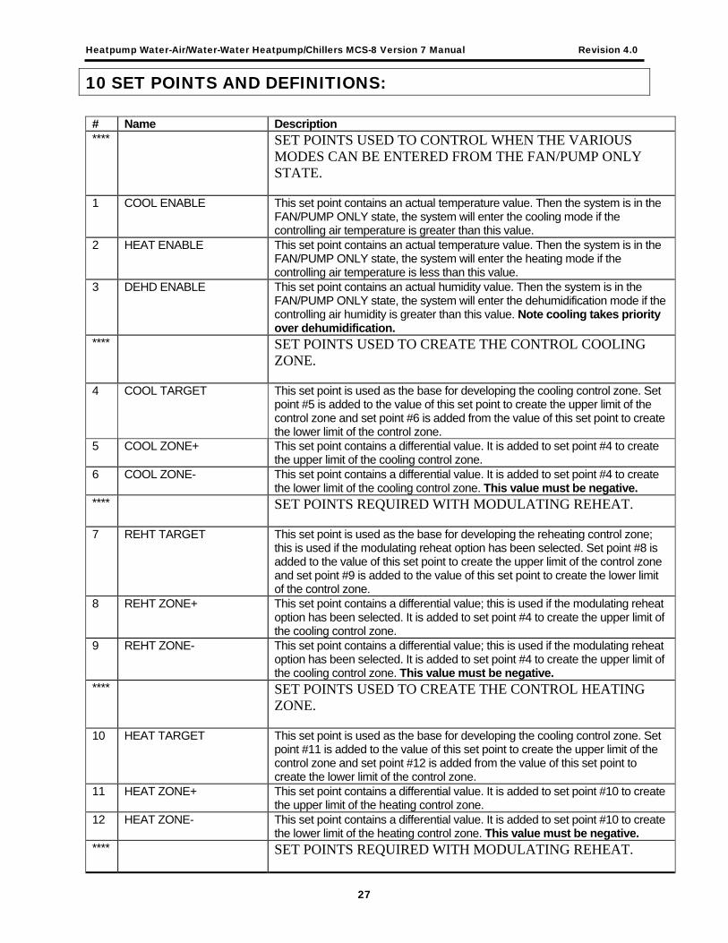
10 SET POINTS AND DEFINITIONS: # Name Description **** SET POINTS USED TO CONTROL WHEN THE VARIOUS
MODES CAN BE ENTERED FROM THE FAN/PUMP ONLY STATE.
1 COOL ENABLE This set point contains an actual temperature value. Then the system is in the FAN/PUMP ONLY state, the system will enter the cooling mode if the controlling air temperature is greater than this value.
2 HEAT ENABLE This set point contains an actual temperature value. Then the system is in the FAN/PUMP ONLY state, the system will enter the heating mode if the controlling air temperature is less than this value.
3 DEHD ENABLE This set point contains an actual humidity value. Then the system is in the FAN/PUMP ONLY state, the system will enter the dehumidification mode if the controlling air humidity is greater than this value. Note cooling takes priority over dehumidification.
**** SET POINTS USED TO CREATE THE CONTROL COOLING ZONE.
4 COOL TARGET This set point is used as the base for developing the cooling control zone. Set point #5 is added to the value of this set point to create the upper limit of the control zone and set point #6 is added from the value of this set point to create the lower limit of the control zone.
5 COOL ZONE+ This set point contains a differential value. It is added to set point #4 to create the upper limit of the cooling control zone.
6 COOL ZONE- This set point contains a differential value. It is added to set point #4 to create the lower limit of the cooling control zone. This value must be negative.
**** SET POINTS REQUIRED WITH MODULATING REHEAT.
7 REHT TARGET This set point is used as the base for developing the reheating control zone; this is used if the modulating reheat option has been selected. Set point #8 is added to the value of this set point to create the upper limit of the control zone and set point #9 is added to the value of this set point to create the lower limit of the control zone.
8 REHT ZONE+ This set point contains a differential value; this is used if the modulating reheat option has been selected. It is added to set point #4 to create the upper limit of the cooling control zone.
9 REHT ZONE- This set point contains a differential value; this is used if the modulating reheat option has been selected. It is added to set point #4 to create the upper limit of the cooling control zone. This value must be negative.
**** SET POINTS USED TO CREATE THE CONTROL HEATING ZONE.
10 HEAT TARGET This set point is used as the base for developing the cooling control zone. Set point #11 is added to the value of this set point to create the upper limit of the control zone and set point #12 is added from the value of this set point to create the lower limit of the control zone.
11 HEAT ZONE+ This set point contains a differential value. It is added to set point #10 to create the upper limit of the heating control zone.
12 HEAT ZONE- This set point contains a differential value. It is added to set point #10 to create the lower limit of the heating control zone. This value must be negative.
**** SET POINTS REQUIRED WITH MODULATING REHEAT.
27

Heatpump Water-Air/Water-Water Heatpump/Chillers MCS-8 Version 7 Manual Revision 4.0
# Name Description 13 REHT MINopen This set point is required if the modulating reheat option has been selected. It
contains minimum percentage that the reheat valve will be opened. Normally set to 0.
14 REHT MINopen This set point is required if the modulating reheat option has been selected. It contains maximum percentage that the reheat valve will be opened. Normally set to 100.0.
15 REHT ADJ MUL This set point is required if the modulating reheat option has been selected. This set point contains a value that is used to adjust the changes to the reheat valve. The adjustment is first calculated by taking the absolute value of the difference between the control temperature and the reheat target. This adjustment is then fine tuned by multiplying by this set point and then dividing by set point 19.
**** SETPOINTS USED TO CREATE THE CONTROL DEHUMIDICATION ZONE.
16 DEHD TARGET This set point is used as the base for developing the dehumidification control zone. Set point #17 is added to the value of this set point to create the upper limit of the control zone and set point #18 is subtracted from the value of this set point to create the lower limit of the control zone.
17 DEHUM ZONE+ This set point contains a differential value. It is added to set point #16 to create the upper limit of the dehumidification control zone.
18 DEHUM ZONE- This set point contains a differential value. It is subtracted from set point #16 to create the lower limit of the dehumidification control zone.
19 REHT ADJ DIV Refer to set point 15. **** TIMING SET POINTS.
20 OverrideTime Time expressed in minutes that when the MCS-STAT over ride button is depressed that the system’s schedule will be active.
21 STARTUP DLY Upon a computer reset or power return, the system will remain in the STARTUP DELAY state for this period of time.
22 FAN DELAY The minimum time that the system will be in the FAN ONLY STATE. 23 STEP DELAY This is the minimum time that the system will remain in each state unless
otherwise noted. **** SETPOINTS FOR STATIC PSI & FAN CONTROL
24 STATIC TRG The static pressure target. If the static psi value is within ± the STATIC DEAD BAND of the target no change is made to the current fan speed. If the current static psi is > ± 0.5 of the target the fan speed is changed by 5 %; otherwise the fan speed is changed by 1%.
25 STATIC DBAND The static dead band is the ± value to the static target, which is allowed with no change to the fan speed.
26 FANSP INTVAL The fan speed interval is the time, in seconds, between fan speed changes. 27 FAN MIN STRT The fan speed minimum start is the starting speed of the fan when it has been
off. **** SETPOINTS USED FOR CONTROL OF ECONOMIZER.
28 ECON CL ON If the entering water temperature is less than this value minus a dead band of 0.5F, the cooling economizer will be used.
29 ECON HT OFF If the entering water temperature is greater than this value plus a dead band of 0.5F, the heating economizer will be used.
**** SETPOINTS THAT ARE TESTED FOR SAFETY CONDITIONS.
30 EVAP OVRFLW1 If the evaporator overflow1 digital input is turned on the system locks off all relay output points except the alarm.
28

Heatpump Water-Air/Water-Water Heatpump/Chillers MCS-8 Version 7 Manual Revision 4.0
# Name Description 31 EVAP OVRFLW2 If the evaporator overflow2 digital input is turned on the system locks off all
relay output points except the alarm. 32 DIGITAL SAFETY If the set point is set to ‘ACTIVE’ in the PC-Config program it will cause the
system to test the digital input that indicates that a safety has occurred. When active and the digital input is on, the system will enter a SAFETY FAULT state. If this set point has been set up as an ‘ALARM only type, no manual intervention will be required to restart the system if the safety condition becomes false. If in the PC-Config program it is setup as a ‘LOCKOUT’ manual intervention will be required.
33 NO FLOW This set point indicates there is no water flow to the system. If the system is running everything is shut down except the fan. A safety alarm is generated. If the system is off it is not allowed to start until flow is detected.
34 COND FREEZE If leaving water temperature to the condenser drops below this set point value, the system will enter the SAFETY FAULT OR LOCKOUT state and the COND FREEZE alarm message will be generated. Purpose is to prevent freeze up.
35 EVAP FREEZE If entering water temperature to the evaporator drops below this set point value, the system will enter the SAFETY FAULT OR LOCKOUT state and the EVAP FREEZE alarm message will be generated. Purpose is to prevent freeze up.
36 LOW SUCT PSI This may be a digital input or an analog input, by compressor. When the condition occurs an alarm is generated identifying the compressor with low suction and the compressor is placed in LOCKOUT. After the delay time the compressor will be automatically placed back into service. If the condition, to the same compressor, occurs a second time within an hour, the compressor is placed into lockout and requires a manual reset.
37 DIGITAL LOCKOUT This set point, when active will cause the system to test the digital input that indicates that a lockout condition has occurred. When active and the digital input is on, the system will enter a LOCKOUT FAULT state. If this set point is set up as a lockout type, manual intervention, lockout reset, will be required to restart the system.
38 NO AIR FLOW This set point indicates there is no airflow to the system. If the system is running everything is shut down except the fan. A safety alarm is generated. If the system is off it is not allowed to start until flow is detected.
39 HI DISC PSI This may be a digital input or an analog input, by compressor. When the condition occurs an alarm is generated identifying the compressor with high discharge and the compressor is placed in LOCKOUT. After the delay time the compressor will be automatically placed back into service. If the condition, to the same compressor, occurs a second time within an hour, the compressor is locked out and requires a manual reset.
**** SETPOINTS USED TO ALLOW OR DISALLOW DEHUMIDICATION.
40 ALLOW DEHUMD This set point contains a temperature value. If the return air temperature is less than the value of this set point, the dehumidification function will be enabled.
41 DISALW DHDIF This set point contains a temperature differential. If the system is in a dehumidification state and the controlling air temperature is greater than the ALLOW DEHUMD value plus the value of this set point, the dehumidification function will be terminated immediately and the system will return to the FAN ONLY.
**** SETPOINTS USED TO ADJUST THE COOL ENABLE SET POINT.
29

Heatpump Water-Air/Water-Water Heatpump/Chillers MCS-8 Version 7 Manual Revision 4.0
# Name Description 42 RETURN RESET This set point is used to calculate a reset to the COOL ENABLE set point. This
set point contains a temperature value that represents the upper limit of the COOL ENABLE temperature range. If the COOL ENABLE temperature is above this value no reset will be made. If the COOL ENABLE temperature is below this value, a proportional reset will be made as described in set point MAX RESET.
43 RETURN DIFF This set point is used to calculate a dynamic reset to the COOL ENABLE set point, set point #1. This set point contains a temperature differential value that is subtracted for set point #42 to provide the lower limit of the COOL ENABLE temperature range. If the COOL ENABLE temperature is below this value the maximum reset allowed will be made. If the COOL ENABLE temperature is between the value of this set point and set point #42, a proportional reset will be made as described in set point #44.
44 MAX RESET This set point contains the maximum temperature reset that can be made to the COOL ENABLE set point, set point #1. If the COOL ENABLE temperature is in the range developed with the values of set points #42 and #43, a proportional reset is calculated based on the COOL ENABLE temperatures position within the range times the value of this set point. This value is added to the COOL TARGET set point. (If the COOL ENABLE temperature is in the middle of the range, a reset of 50% of this value would be added to the COOL ENABLE.
45 RESET DELAY This set point contains a time, in seconds, that controls the delay between reset calculations. This is intended to dampen the changing of the COOL TARGET temperature target.
**** SETPOINTS USED TO MODULATE THE HOT WATER VALVE.
46 HW VLV MIN% This set point contains minimum percentage that the valve will be opened. Normally set to 2.0.
47 HW VLV MAX% This set point contains maximum percentage that the valve will be opened. Normally set to 100.0.
48 HW MIN ADJ% This set point contains the minimum adjustment that can be made to the valve at one time.
49 HW MAX ADJ% This set point contains the maximum adjustment that can be made to the valve at one time.
50 HW VLV DELAY This set point contains the time expressed in seconds between modulating the valve.
51 HW VLV MULT This set point contains a value that is used to adjust the changes to the valve. The adjustment is first calculated by taking the absolute value of the difference between the control temperature and the heat target. This adjustment is then fine tuned by multiplying by this set point and then dividing by set point 52.
52 HW VLV DIV Refer to set point 51. 53 HW MAX ROC- This set point contains the rate of change that the system uses to determine if
the control temperature is changing too fast or too slow. 54 HW ROC DELAY This set point contains the time expressed in seconds between calculating the
rate of change of the control temperature. **** SETPOINTS USED TO MODULATE THE ECONOMIZER and
the REHEAT VALVES.
55 ECON VLV MIN This set point contains the minimum valve opening. If the unit has a valve that can be modulated, its percent of opening will be modulated between this set point and set point 54 based upon the control temperature. In this way the system maximizes the econo cooling or heating capability.
56 ECON VLV MAX This set point contains the maximum valve opening. Refer to set point 54.
30

Heatpump Water-Air/Water-Water Heatpump/Chillers MCS-8 Version 7 Manual Revision 4.0
# Name Description 57 REHT MINadj This set point is required if the modulating reheat option has been selected.
This set point contains the minimum adjustment that can be made to the reheat valve at one time.
58 REHT MAXadj This set point is required if the modulating reheat option has been selected. This set point contains the maximum adjustment that can be made to the reheat valve at one time.
59 REHT DELAY This set point is required if the modulating reheat option has been selected. This set point contains the time expressed in seconds between modulating the reheat valve.
60 TEST CFG I/O If this setpoint is active and set to 0, the system will not lock out due to lost I/O’s. This is used only for testing a system. Note the alarm and message will be generated.
31

Heatpump Water-Air/Water-Water Heatpump/Chillers MCS-8 Version 7 Manual Revision 4.0
11 Return Air Target Reset Logic #42 RETURN RESET = 70.0F – Temperature at which target reset starts #43 RETURN DIFF = 10.0F – Temperature offset from starting return temperature #44 MAX RESET = 10.0F – Maximum reset adjustment allowed #45 RESET DELAY = 600s – Time delay between making adjustments
Cool Target Reset
0
1
2
3
4
5
6
7
8
9
10
60 61 62 63 64 65 66 67 68 69 70
Return Temperature
Targ
et R
eset
32

Heatpump Water-Air/Water-Water Heatpump/Chillers MCS-8 Version 7 Manual Revision 4.0
12 AUTHORIZATION FUNCTION The authorization code is a special four-character code that enables access in to the MCS-8 system. The code must be numeric, with values between 1 and 8, if it is to be entered from the Keypad/Display. If the system is being accessed via PC-Connection program, the code may consist of any valid alpha/numeric characters. Each system can have up to 15 different authorization codes. This provides the capability of issuing different codes to different people if desired. There are four levels of authorization, which provide different capabilities with in the system. The authorization code and the associated level cannot be displayed or viewed in an MCS-8 system. These are established when building the configuration file in the PC-Configuration program. The authorization codes must be protected and remain confidential, if they are compromised unauthorized personnel can gain access to the system. From the Keypad/Display the following changes can be made based upon the authorization level:
FUNCTION VIEW SERVICE SUPERVI-SORY
FACTORY
SENSOR OFFSETS NO YES YES YES SENSOR DIAGNOSTIC NO YES YES YES CLEAR ALARM HISTORY NO NO NO YES CLEAR POINT INFORMATION NO NO NO YES UNIT INFORMATION / NETWORK ADDRESS NO YES YES YES DATE & TIME SET YES YES YES YES DAY OF WEEK SET YES YES YES YES CHANGE OPERATING SCHEDULES NO YES YES YES CHANGE MANUAL/AUTO SETTINGS NO NO YES YES CHANGE SET POINT VALUES* NO YES YES YES LOCK OUT RESET YES YES YES YES ACTIVATE / INACTIVATE AUTO ROTATION NO NO NO YES CHANGE UNIT ADDRESS NO YES YES YES CHANGE HARDWARE VERSION NUMBER NO NO NO YES
33

Heatpump Water-Air/Water-Water Heatpump/Chillers MCS-8 Version 7 Manual Revision 4.0
13 The Micro Control Center Keypad Display Quick Reference • No authorization is required in the DISPLAY STATUS section for viewing information. • Pressing a key selects the 1st two lines of data. Repressing the same key selects the next two lines, etc. • The ALARM STATUS displays all alarms and lockouts while LOCKOUT STATUS displays only active lockouts. • The “+” and “-“ keys may be used with alarm & lockout status to allow scrolling. • If one or more Micro Control Expansion units are connected to a Micro Control Center the data will be presented in a continuous sequence.
• ADDITIONAL STATUS information shows names, total, run hours and starts for all RO’s. • SYSTEM PRESSURE displays information by circuit, SP suction pressure, DP discharge pressure, OPD oil pump differential, AMP or motor fault. • LOCKOUT STATUS for lockouts caused by either suction discharge oil or amps, the actual value at the time of the lockout of the associated sensor is displayed.
DISPLAY STATUS
7
COMP1 ONCOMP2 ON
REV VALV ONECON H/C ON
REHEAT OFFEND /SELECT NEXT
END /SELECT NEXT
RETURN T+ 43.3%RETURN H+ 77.6F
SUPPLY T+ 2.3”STATIC P RUN
RUN/STOP OFFWTR FLOW OFF
SAFETIES OFFEND /SELECT NEXT
FAN =1015HSTARTS=0000210
ECON VLV=1002HSTARTS =000201
REV VLV=10020HSTARTS = 00201
NEWEST LKOUT 1 STENTR NEW/OPTION
WATER FREEZE AUG 26 0:28:37
END OF LOCKOUTSENTR VIEW OPTION
8
6
51
2
3
4
SYSTEM PRESSURE
COMPRESSORSTATUS
CONDENSORSTATUS
EVAPORATORSTATUS
ALARM STATUS
SYSTEM SENSORS
ADDITIONTAL STATUS INFO.
LOCKOUT STATUS
HP Configuration #1 WATER FREEZE AUG 26 0:28:37 #2 POWER RETURNED APR 22 8:15:01 #3 POWER FAILED APR 22 8:10:15
FAN ON END /SELECT NEXT
ENT WTR+ 43.4FLEV WTR + 88.1F
REHEAT ON END /SELECT NEXT
• Single board heat pump • Two compressors • One valve to control • One reversing • One reheat point that control
compressors reheat • Safety & lockout digital • Measure static duct pressure • Control is on return air
34

Heatpump Water-Air/Water-Water Heatpump/Chillers MCS-8 Version 7 Manual Revision 4.0
14 The Micro Control Center Keypad Display Quick Reference-ENTRY KEYS
• The ENTRY keys (SERVICE, SETPOINT, MANUAL and PROGRAM) provide menu items, some of which when selected will present sub menus. • When making value changes the INCREASE (+) & DECREASE (-) keys may be held for continuous updating. • Enter authorization code at the authorization function within the SERVICE DIAGNOSTIC key menu.
• Different items will appear depending on the package configuration and options selected. • Units may be English or Metric. • The clock is factory set at EST or EDST based on time of year.
ENTRY
#1 COOL ENABLE ENTR CHG +70.0F
#4 COOL TARGET ENTR CHG +50.0F
#5 COOL ZONE+ ENTR CHG +5.0F
#6 COOL ZONE- ENTR CHG –5.0F
#21 STARTUP DLY ENTR CHG +25
#22 FAN DELAY ENTR CHG +60
#23 STEP DELAY ENTR CHG +300
#24 STATIC TRG ENTR CHG +1.5
AUTHORIZATION ENTR CHG OPTION
SENSOR OFFSETS ENTR CHG OPTION
SENSOR DIAGOSTIC ENTR CHG OPTION
CLEAR ALRM HSTRY ENTR CHG OPTION
UNIT INFORMATION ENTR CHG OPTION
CONTROL STATUS ENTR CHG OPTION
CLEAR PT INFO ENTR CHG OPTION
TIME DISPLAY ENTR CHG OPTION
DATE & TIME SET ENTR CHG OPTION
DAY OF WEEK SET ENTR CHG OPTION
OPERATING SCHEDS ENTR CHG OPTION
DATE DISPLAY ENTR CHG OPTION
RELAY OUTS MANAL ENTR CHG OPTION
ANALG OUTS MANAL ENTR CHG OPTION
SENSOR INS MANAL ENTR CHG OPTION
RESET LOCKTS? ENTER KEY=YES
ENTER KEY Selects options or enters
changes after adjustments have been made.
INCREASE (+) KEY &
DECREASE (-) KEY
Used To adjust values or change options selected.
(SERVICE, SETPOINTS, MANUAL, &
PROGRAM keys.)
SERVICE DIAGNOSTI
SETPOINTS (SAFETIES)
MANUAL (AUTO)
LOCKOUT RESET
PROGRAM OPTIONS
INCREASE (+)
DECREASE (-)
ENTER
35

Heatpump Water-Air/Water-Water Heatpump/Chillers MCS-8 Version 7 Manual Revision 4.0
15 The Micro Control Center MCS-8 Quick Reference Sheet Wiring Guide Notes
• Relay Outputs (RO) 120 VAC 10 amps on the MCS-8. • SI factory settings for analog inputs. (0 to 5 volts dc) • All analog inputs must have shield tied to GND. • MCS-8 factory set address to MCS-8. • MCS-I/O factory set address to MCSIO#1. • Details of theMCS-8 items are on the next page. • Details of the MCS-SI8/16 items are following the MCS-8 page.
High Voltage Wireway Relay Ouptus & 120 VAC 50/60 hertz InputPreferred direction of wire
Low Voltage Wireway Sensor Input, Analog Output & CommunicationsTerminals Shielded cable only, preferred direction of wire
120 VAC
KeypadConnector
LCD ContrastAdjustment
LCDConnector
U14
U11
U10
315 ma Fuse
RO # 1
10 A Fuse #1
RO # 2
10 A Fuse #2
RO # 3
10 A Fuse #3
RO # 4
10 A Fuse #4
RO # 5
10 A Fuse #5
RO # 6
10 A Fuse #6
RO # 7
10A Fuse #7
RO # 8
10A Fuse #8
MCS-8Rev. 1.5© 1998Micro ControlSystems, Inc.Fort Myers,Florida
BoardSelect
MCSIO#1
MCSIO#2
MCSIO#3
"""
Static RAM
SoftwareEPROM
ConfiguratorEEROM
XFMER8/16AC
8/16vdcterm
System uses eitherXFMER or DC input
XFMER8/16AC
ResetSwitch
+12VDC
AnalogOutput
RS485
MCS IO
CommunicationsTerminal RS232 – 9 pin
female connection
RS232
:
SI/AI #1 SI/AI #2 SI/AI #3 SI/AI #4
DigitalAnalog : : : : : : : :Digital
AnalogDigitalAnalog
DigitalAnalog
SI/AI #5 SI/AI #6 SI/AI #7 SI/AI #8
DigitalAnalog : : : : : : : :Digital
AnalogDigitalAnalog
DigitalAnalog :
36

Heatpump Water-Air/Water-Water Heatpump/Chillers MCS-8 Version 7 Manual Revision 4.0
16 Details of MCS-8 Key Items
8 Relay Outputs (RO)
Common NormallyOpen
NormallyClosed
120 VAC 50/60 hertz Input
Line Neutral Ground
Optional UPS
8 VDC Ground 16 VDC
Sensor Inputs 1thru 8
+5VDC Ground Signal
RS485 Communications
+ - Ground
MCS IO Communications
+ - Ground
12 VDC Output max 500ma
+12 VDC Not Used Ground
Analog Output
4 to 20 Ground 0 to 10VDC
120 VAC
KeypadConnector
LCD ContrastAdjustment
LCDConnector
U14
U11
U10
315 ma Fuse
RO # 1
10 A Fuse #1
RO # 2
10 A Fuse #2
RO # 3
10 A Fuse #3
RO # 4
10 A Fuse #4
RO # 5
10 A Fuse #5
RO # 6
10 A Fuse #6
RO # 7
10A Fuse #7
RO # 8
10A Fuse #8
MCS-8Rev. 1.5© 1998Micro ControlSystems, Inc.Fort Myers,Florida
BoardSelect
MCSIO#1
MCSIO#2
MCSIO#3
"""
Static RAM
SoftwareEPROM
ConfiguratorEEROM
XFMER8/16AC
8/16vdcterm
System uses eitherXFMER or DC input
XFMER8/16AC
ResetSwitch
+12VDC
AnalogOutput
RS485
MCSIO
CommunicationsTerminal RS232 – 9 pin
female connection
RS232
:
SI/AI #1 SI/AI #2 SI/AI #3 SI/AI #4
DigitalAnalog : : : : : : : :Digital
AnalogDigitalAnalog
DigitalAnalog
SI/AI #5 SI/AI #6 SI/AI #7 SI/AI #8
DigitalAnalog : : : : : : : :Digital
AnalogDigitalAnalog
DigitalAnalog :
37

Heatpump Water-Air/Water-Water Heatpump/Chillers MCS-8 Version 7 Manual Revision 4.0
17 Details of MCS-SI8/16 Key Items
Sensor Input 1-8
38
120/24VAC
315ma/2a XFMER 8/16 AC
(8VAC only used)
Reset Switch
MCS IOSI #9 SI #10 SI #11 SI #12
: : : : : : : :
SI #13 SI #14 SI #15 SI #16
: : : : : : : :DigitalAnalog
DigitalAnalog
DigitalAnalog
DigitalAnalog
DigitalAnalog
DigitalAnalog
DigitalAnalog
DigitalAnalog
:
SI #1 SI #2 SI #3 SI #4
: : : : : : : :
SI #5 SI #6 SI #7 SI #8
: : : : : : : :
12345678
ADDRESS
DigitalAnalog
DigitalAnalog
DigitalAnalog
DigitalAnalog
DigitalAnalog
DigitalAnalog
DigitalAnalog
DigitalAnalog
+5VDC Ground Signal
Sensor Input 9-16+5VDC Ground Signal

Heatpump Water-Air/Water-Water Heatpump/Chillers MCS-8 Version 7 Manual Revision 4.0
18 The MCS Sensors Quick Reference Sheet – Temperature, Supply Air, Humidity & Pressure transducers
MCS-SAIR (SI Revision 1.5 & Higher)
1. Connects to 1 of MCS Sensor Inputs 1 through 8/16 2. Shielded cable GND drain must be connected to SI ‘GND’3. Temperature MCS-8 SI jumper settin g
Minimum extension inside duct 2.25” 4. 5. Normal extension, as shown, 4.00”.
MCS Sensor Input Terminal Strips
BLK WH
+5 GND S1Shielded cable - 18’ 24 awg supplied
Min = 2.125” Max = 4.500”
MCS-SAIR
MCS-T100 (SI Revision 1.5 & Higher) 1. Connects to 1 of MCS Sensor Inputs 1 through 8/162. Shielded cable GND drain must be connected to SI ‘GND’3. Temp MCS-8 SI jumper setting
MCS-HUMD (Revision 1.5 & Higher) 1. Connects to 2 of MCS Sensor Inputs 1 through 8/16 2. +5 vdc & GND are common (one connection required) 3. Temp. & Humd. MCS-8 SI jumper settings 4. Shielded cable GND drain must be connected to SI ‘GND’
MCS Sensor Input Terminal Strips+12 OUT SENSOR (x1) SENSOR(x2)
+12 GND +5 GND S1 +5 GND
TI / ECLIP (SI Revision 1.5 & Higher) 1. TI / ECLIP pressure transducer (3 wire .5-4.5 vdc) 2. Shielded cable GND drain must be connected to SI GND’ 3. Jumper settings for SI 1 through 8/16 4. Pressure range 0 - 500 psi
: :DigitalAnalog
MCS Sensor Input Terminal Strips SENSOR (x)
RED WH
+5 GND
Shielded cable - (20’ or 40’ 22 awg li d)
BLK
TI / ECLIP
S1
: :DigitalAnalog
MCS-H100
+5 VD GND Out
Tem
+12 VDC GND Humd
Circuit
S1
: :DigitalAnalog: :Digital
Analog
MCS-T100
MCS Sensor Input Terminal Strips
awg suppliedShielded cable - 18’ 24
BLK WH
S1 GND +5
39

Heatpump Water-Air/Water-Water Heatpump/Chillers MCS-8 Version 7 Manual Revision 4.0
19 The MCS Sensors Quick Reference Sheet - Dry Contact Inputs
Dry Contact’s (SI 1 through 8 Revision 1.5 & Higher)1. Digital inputs for use on sensor inputs (SI 1-8/16)2. Wire between +5 & SI3. Dry Contact MCS-8 jumper setting4. Shielded cable GND drain must be connected to SI “GND”
+5 GND S1
MCS Sensor Input Terminal StripsSensor (x)
Shielded cable - min. 24 awgd d
MCS DRY CONTACT DI (SI 1-8/16)
:DigitalAnalog
40

Heatpump Water-Air/Water-Water Heatpump/Chillers MCS-8 Version 7 Manual Revision 4.0
20 The MCS Trouble Shooting Quick Reference Sheet PROBLEM POTENTIAL SOLUTION A sensor input reads -99.9 1) This indicates an open sensor input signal or 5 VDC problem.
a) Check sensor wiring for missing wire or poor connection. b) Check sensor for bad sensor.
2) If less than 5 VDC on sensor inputs problem with board. a) Remove all sensor input terminals. b) Wait about 1 min. or until 5 VDC restored at sensor input. c) Connect terminals 1 at time until short reappears.
A sensor input reads +999.9 3) This indicates a shorted sensor input signal. a) Check sensor wiring for +5VDC shorted to signal etc. b) Check sensor for bad sensor.
A sensor is reading less then 3% off
4) This indicates the sensor needs to be calibrated. (You need to have a valid Authorization code to change sensor offsets) a) Press Service Diagnostics, press until LCD displays the sensor
offset option b) Press enter, 1st SI# & offset appears (i.e. Suct 1 = 0.0) c) Scroll using “increase (+)/decrease (-)” keys to find sensor to be
calibrated d) Press enter, use the “increase (+)/decrease (-)” keys to change
the calibration value. When value is correct, press enter.
‘MCS CONTROLLER INITIALIZATION’ on LCD display.
5) Indicates Micro in constant reset. a) Check incoming power > 105 VAC or 22 VAC
Top row of LCD display all bars & 2nd row blank.
6) Indicates software chip problem possible. a) Possible U11 software version incorrect or chip is bad. b) Possible U13 GAL chip is incorrect or chip bad. c) Possible bad connection or cable between LCD and MCS8
LCD blank. 7) Indicates bad connection. a) Connector J2 on MCS not on or offset on connector. b) Resistor adjustment VR1 out of adjustment.
Lost I/O 8) Indicates communications problem. a) Verify RS485 LED blinking. b) Verify termination jumper J6 only on at MCS-8 & last I/O. c) Verify MCS-8 & I/O address’s set correctly. d) Verify wiring from MCS-8 to each I/O correct. e) Check fuses/120 VAC on I/O units
Invalid reading on one sensor input.
9) This indicates an input problem with 1 sensor. a) Verify jumper settings correct for that SI.
Changes to MCS not being made. 10) This indicates inability to write to chip U10. a) Verify ‘EEP WRITE ENABLE’ jumper W6 is on. b) Not authorized
Invalid authorization 11) This indicates an invalid authorization #. a) Follow steps below for proper authorization b) Press SERVICE DIAGNOSTICS key; the authorization option
appears c) Press the ENTER key d) From the “Display Status” press keys corresponding to your
authorization # e) Press ENTER
41
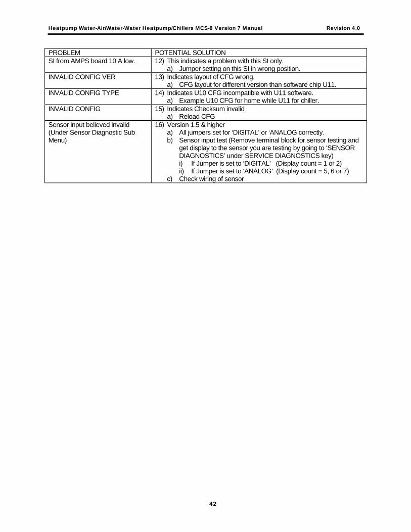
Heatpump Water-Air/Water-Water Heatpump/Chillers MCS-8 Version 7 Manual Revision 4.0
PROBLEM POTENTIAL SOLUTION SI from AMPS board 10 A low. 12) This indicates a problem with this SI only.
a) Jumper setting on this SI in wrong position. INVALID CONFIG VER 13) Indicates layout of CFG wrong.
a) CFG layout for different version than software chip U11. INVALID CONFIG TYPE 14) Indicates U10 CFG incompatible with U11 software.
a) Example U10 CFG for home while U11 for chiller. INVALID CONFIG 15) Indicates Checksum invalid
a) Reload CFG Sensor input believed invalid (Under Sensor Diagnostic Sub Menu)
16) Version 1.5 & higher a) All jumpers set for ‘DIGITAL’ or ‘ANALOG correctly. b) Sensor input test (Remove terminal block for sensor testing and
get display to the sensor you are testing by going to ‘SENSOR DIAGNOSTICS’ under SERVICE DIAGNOSTICS key) i) If Jumper is set to ‘DIGITAL’ (Display count = 1 or 2) ii) If Jumper is set to ‘ANALOG’ (Display count = 5, 6 or 7)
c) Check wiring of sensor
42

Heatpump Water-Air/Water-Water Heatpump/Chillers MCS-8 Version 7 Manual Revision 4.0
21 Summary of Control States The following table contains HEAT PUMP / CHILLER CONTROL STATES. The HEAT PUMP control states can be viewed form the keypad by depressing the SERVICE DIAGNOSTICS key and selecting the CONTROL STATUS function. The first screen contains the state and the time in that state. The + or – keys will move to the ECONOMIZER CONTROL STATES. The following table contains HEATPUMP / CHILLER CONTROL STATES.
NAME DESCRIPTION
LOST I/O The system has detected a failure to communicate to an input or output unit. LOCKOUT FAULT Lock out input is on. Manual intervention is required-LOCKOUT RESET. SAFETY FAULT Safety input is on. System will restart when is input is off if the set point is not a lock
out type. If it is a LOCKOUT RESET is required. SENSOR FAULT One of the sensors has failed either open or closed (999.9 or –99.9). LOCKOUT
RESET is required.
HEATPUMP OFF RUN/STOP switch is off (STOP). FAN/PUMP ONLY FAN or PUMP is ON, no cooling or heating required.
ECONO COOLING Cooling is being provided by the economizer function. COOL: 1 COMP Compressor 1 is providing cooling. COOL: 2 COMPS Compressors 1& 2 are providing cooling. COOL: 3 COMPS Compressors 1, 2 & 3 are providing cooling. COOL: 4 COMPS Compressors 1,2, 3 & 4 are providing cooling.
DEHUM: 1 COMP Compressor 1 is providing dehumidification. DEHUM: 2 COMPS Compressors 1& 2 are providing dehumidification. DEHUM: 3 COMPS Compressors 1, 2 & 3 are providing dehumidification. DEHUM: 4 COMPS Compressors 1,2, 3&4 are providing dehumidification.
ECONO HEATING Heating is being provided by the economizer function.
HEAT: 1 COMP Compressor 1 is providing heating. HEAT: 2 COMPS Compressors 1& 2 are providing heating. HEAT: 3 COMPS Compressors 1, 2 & 3 are providing heating. HEAT: 4 COMPS Compressors 1,2, 3 & 4 are providing heating.
HEAT-HOLDING Heating is being provided by hot water and the valve is not being modulated. HEAT-CLOSING Heating is being provided by hot water and the valve is being modulated closed.
The control temperature is with in the control heat zone. HEAT-OPENING Heating is being provided by hot water and the valve is being modulated open. The
control temperature is with in the control heat zone. HEAT-SLOPE CL Heating is being provided by hot water and the valve is being modulated closed.
The control temperature is not with in the control heat zone. Percentage of closing is calculated based on current control temperature and heat target.
HEAT-SLOPE OP Heating is being provided by hot water and the valve is being modulated open. The control temperature is not with in the control heat zone. Percentage of opening is calculated based on current control temperature and heat target.
ELECTRIC HEAT Heating is being provided electric heat.
43
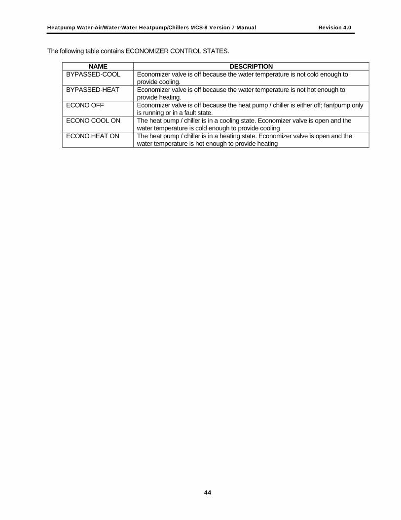
Heatpump Water-Air/Water-Water Heatpump/Chillers MCS-8 Version 7 Manual Revision 4.0
The following table contains ECONOMIZER CONTROL STATES.
NAME DESCRIPTION BYPASSED-COOL Economizer valve is off because the water temperature is not cold enough to
provide cooling. BYPASSED-HEAT Economizer valve is off because the water temperature is not hot enough to
provide heating. ECONO OFF Economizer valve is off because the heat pump / chiller is either off; fan/pump only
is running or in a fault state. ECONO COOL ON The heat pump / chiller is in a cooling state. Economizer valve is open and the
water temperature is cold enough to provide cooling ECONO HEAT ON The heat pump / chiller is in a heating state. Economizer valve is open and the
water temperature is hot enough to provide heating
44