MCPC TR-021 Safety Design Guideline for USB Interface …mcpc-jp.org/news/pdf/MCPC...
17
MCPC TR-021 Safety Design Guideline for USB Interface for Charging Version 1.01 (E) July 1, 2015 Mobile Computing Promotion Consortium Technical committee
Transcript of MCPC TR-021 Safety Design Guideline for USB Interface …mcpc-jp.org/news/pdf/MCPC...
MCPC TR-021
Safety Design Guideline for
USB Interface for Charging
Version 1.01 (E)
July 1, 2015
Mobile Computing Promotion Consortium
Technical committee
Copyright 1997-2015 Mobile Computing Promotion Consortium (MCPC) MCPC TR-021 Safety Design Guideline for USB Charging Interface Version 1.00(E)
i
Change history Date Version Changes
June 25, 2015 1.00(E) English translation version release
July 1, 2015 1.01(E) Amendment of the sentence
Notice
This Guideline is the translation from MCPC TR-021 only for the benefit of English readers. The original version of MCPC TR-021 shall be the official specifications in its interpretation, construction and understanding.
Copyright 1997-2015 Mobile Computing Promotion Consortium (MCPC) MCPC TR-021 Safety Design Guideline of USB Interface for Charging Version 1.00(E)
ii
Published and copyrights owned by: Mobile Computing Promotion Consortium (MCPC) Hasegawa Green Building, 5-12 Shiba-Koen 3-chome, Minato-ku, Tokyo, 105-0011 Japan
TEL: +81-3-5401-1935
FAX: +81-3-5401-1937 EMAIL: [email protected] WEB SITE: http://www.mcpc-jp.org
Confidentiality The MCPC Rules and the MCPC IPR Policy Shall Apply.
Disclaimer This document is intended to provide standard specifications and recommended specifications, etc. on mobile computing. Mobile Computing Promotion Consortium (hereafter MCPC) shall not be liable for any direct, indirect or consequential damages or infringements to patents or any other rights held by the third parties arising out of using this Specifications. This document shall not be construed to grant (a) license(s) under any rights held by MCPC or the third parties.
How do we distinguish binary, decimal and hexadecimal numbers? For binary numbers, we append small letter “b” (e.g. 10b)).
For binary numbers, we insert a space after every four bits. (e.g.:1000 0101 0010b).
For hexadecimal numbers, we append small letter “h” (e.g.:FFFFh and 80h).
All other numbers shall be considered to be written in decimal.
Key Words “May” means that something is recommended or optional at the free discretion of the vendor.
“Should” means that although something is not essential, it is strongly recommended. When implementing, the vendor
shall take this requirement into consideration and determine whether this is essential or not.
“Shall” means that something is an essential requirement. For connectivity and specification compliance, the feature
must be implemented, and is mandatory.
Trademark Notes Company names, product names, service names and the like described in this document are generally trademarked
or are registered trademarks of their respective owners.
In general, the usage of ™ marks, © marks, and ® marks has been omitted in this document.
In general “Inc.,” “Corporation,” “Co., Ltd.,” have been excluded from company names.
Application note It is indicating as follows, when indicating a case of the operation on a document. :
Application note : Case-of-the-operation entry
Copyright 1997-2015 Mobile Computing Promotion Consortium (MCPC) MCPC TR-021 Safety Design Guideline of USB Interface for Charging Version 1.00(E)
iii
Table of Contents
1. Introduction ........................................................................................................... 1
2. The case history of an accident at USB charging .............................................. 1
3. USB Charger Functionality Outline ..................................................................... 2
3.1 USB Charging Environment and the Scope of this Guideline ............................................. 2
3.2 Overview on USB charging interface specification ............................................................. 3
4. USB charging safety design specifications ........................................................ 4
4.1 Power supply input and output parameters ........................................................................ 4
5. USB charge safety design parameter list ............................................................ 5
5.1 Charging adapter input/output parameters ........................................................................ 5
5.2 Safety parameters of charging adapter .............................................................................. 6
5.3 Regulation of charging equipment ..................................................................................... 7
6. Notes for designing a USB charging interface ................................................... 8
6.1 The requirements for an AC/DC adapter ............................................................................ 8
6.2 The requirements for a mobile battery ............................................................................... 8
Appendix A. Reference specifications (Normative) ................................................... 9
Appendix B. Half short error and its counter measure examples ............................ 10
Appendix C. Related specifications (for further investigation) .............................. 11
Copyright 1997-2015 Mobile Computing Promotion Consortium (MCPC) MCPC TR-021 Safety Design Guideline of USB Interface for Charging Version 1.00(E)
iv
Table of Figures
Figure3-1 The variety of USB charging environments and the scope of this Edition ........................ 2 Figure3-2 Charging equipment and charging adapter ....................................................................... 3
Copyright 1997-2015 Mobile Computing Promotion Consortium (MCPC) MCPC TR-021 Safety Design Guideline for USB Charging Interface Version 1.00(E)
1
1. Introduction An USB interface is used as a power charge interface by many smaller peripherals, and the Micro USB interface especially is widely implemented for smart phones, etc. When USB has become widely used as a charging interface, some problems have started to be recognized in the market, such as causing a charging terminal fire and a higher temperature due to inappropriate uses by consumers or inappropriate implementations of safety circuits in the products. This Guideline specifies the technical parameters for charging smart phones and other equipment which support Micro USB as a charging interface, for the purpose of the improvement in charging safety, a charging terminal fire prevention, and the heat generation control for a Micro USB interface. This Guideline is intended to serve as the baseline for a safety design of a charging interface. The test specifications for a safety design certification and user promotion activities for safe charging will be followed.
2. The case history of an accident at USB charging These are the cases of accidents that occurred during USB charging. The purpose of this document is to reduce the risk of such accidents.
i. The half short of a charging terminal When conductive substances (ex. metal or moisture) attach to a connector terminal, or the resulting corrosion of the metal between connector terminals or between a connector terminal and a connector shell generates a half-energized state, the current that flows out of them may cause heat generation and fire . In this Guideline, the term “charging terminal” includes both the power related terminals (Vbus, GND) of a Micro USB connector and a connector shell.
ii. Short-circuit of the terminals by deforming a Micro USB connector
Inadequate handling of a connector, a charging terminal and a connector body cause them deformed resulting short circuit. There is a risk of generating high heart and fire when a short protection function is not implemented in charging adapter.
iii. Connection of an out-of-spec charging adapter and charging equipment The electrical specifications of a charging adapter and charging equipment need to be matched. The charge cable that is specified or certified by a charging adapter and charging equipment must be used. Use of charging adapters or cables outside the specifications may generate higher heat and fire by the short circuit that is caused by electric mismatching or inappropriate insulation, or the impedance of a cable itself.
iv. Connecting a charging adapter without overcurrent and overvoltage protection Charging with a charging adapter without overcurrent/overvoltage protection functions may generate higher heat and fire, when current beyond the capability of a charging adapter flows.
Copyright 1997-2015 Mobile Computing Promotion Consortium (MCPC) MCPC TR-021 Safety Design Guideline of USB Interface for Charging Version 1.00(E)
2
3. USB Charger Functionality Outline
3.1 USB Charging Environment and the Scope of this Guideline USB interface is the specifications which USB Implementers Forum developed for the purpose of data
communications by connecting host equipment (such as PC) with external devices using a cable. In order to connect small external devices without an external power supply, electric power can be supplied.
With the wide adoption of the USB interface to PCs, it is now used not only as a communication interface, but also as an electric power supply interface. It serves as a common power supply interface for small equipment such as smart phones.
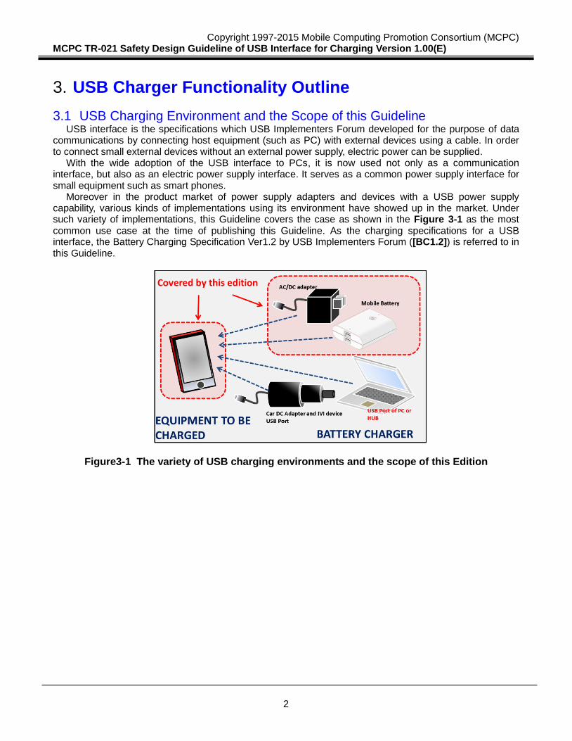
Moreover in the product market of power supply adapters and devices with a USB power supply capability, various kinds of implementations using its environment have showed up in the market. Under such variety of implementations, this Guideline covers the case as shown in the Figure 3-1 as the most common use case at the time of publishing this Guideline. As the charging specifications for a USB interface, the Battery Charging Specification Ver1.2 by USB Implementers Forum ([BC1.2]) is referred to in this Guideline.
Figure3-1 The variety of USB charging environments and the scope of this Edition
Copyright 1997-2015 Mobile Computing Promotion Consortium (MCPC) MCPC TR-021 Safety Design Guideline of USB Interface for Charging Version 1.00(E)
3
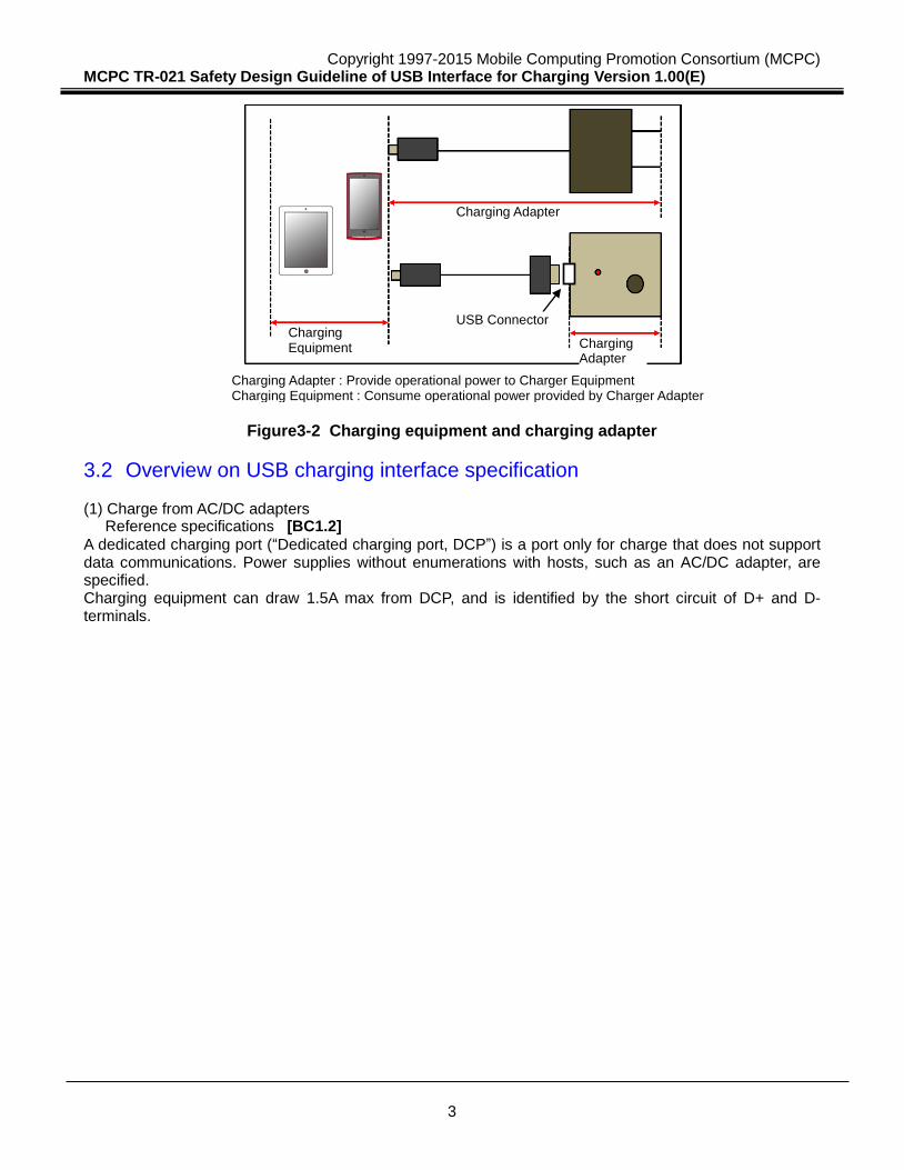
Figure3-2 Charging equipment and charging adapter
3.2 Overview on USB charging interface specification (1) Charge from AC/DC adapters Reference specifications [BC1.2] A dedicated charging port (“Dedicated charging port, DCP”) is a port only for charge that does not support data communications. Power supplies without enumerations with hosts, such as an AC/DC adapter, are specified. Charging equipment can draw 1.5A max from DCP, and is identified by the short circuit of D+ and D- terminals.
Charging Equipment Charging
Adapter
Charging Adapter
Charging Adapter : Provide operational power to Charger Equipment Charging Equipment : Consume operational power provided by Charger Adapter
USB Connector
Copyright 1997-2015 Mobile Computing Promotion Consortium (MCPC) MCPC TR-021 Safety Design Guideline of USB Interface for Charging Version 1.00(E)
4
4. USB charging safety design specifications
4.1 Power supply input and output parameters This parameter specifies the fundamental electric conditions over charging adapter. The parameters do not directly enhance the safety of charges. However, they serve as important design guidelines for the fundamental safety base. (1) Power adapter parameter The parameter specifies a DC power supply which is sourced from AC power. As a prerequisite, the regulation by the Electrical Appliance and Material Safety Law ([EAMS]) shall be observed for the parameters for AC/DC adapters. This Guideline sets forth the recommended operating environments for safe and stable operations. (2) USB output parameter The parameter specifies a USB output to charging adapter. In addition to the DCP support, this Guideline sets forth the recommended operating environments for safe and stable operations.
Copyright 1997-2015 Mobile Computing Promotion Consortium (MCPC) MCPC TR-021 Safety Design Guideline of USB Interface for Charging Version 1.00(E)
5
5. USB charge safety design parameter list
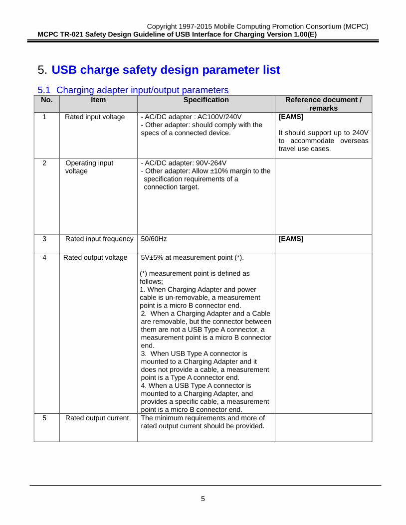
5.1 Charging adapter input/output parameters No. Item Specification Reference document /
remarks 1 Rated input voltage - AC/DC adapter : AC100V/240V
- Other adapter: should comply with the specs of a connected device.
[EAMS] It should support up to 240V to accommodate overseas travel use cases.
2 Operating input voltage
- AC/DC adapter: 90V-264V - Other adapter: Allow ±10% margin to the specification requirements of a connection target.
3 Rated input frequency 50/60Hz [EAMS]
4 Rated output voltage 5V±5% at measurement point (*). (*) measurement point is defined as follows; 1. When Charging Adapter and power cable is un-removable, a measurement point is a micro B connector end. 2. When a Charging Adapter and a Cable are removable, but the connector between them are not a USB Type A connector, a measurement point is a micro B connector end. 3. When USB Type A connector is mounted to a Charging Adapter and it does not provide a cable, a measurement point is a Type A connector end. 4. When a USB Type A connector is mounted to a Charging Adapter, and provides a specific cable, a measurement point is a micro B connector end.
5 Rated output current The minimum requirements and more of rated output current should be provided.
Copyright 1997-2015 Mobile Computing Promotion Consortium (MCPC) MCPC TR-021 Safety Design Guideline of USB Interface for Charging Version 1.00(E)
6
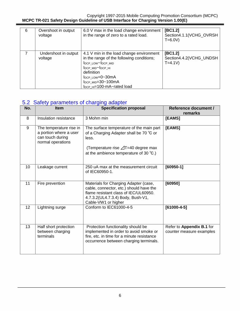
6 Overshoot in output voltage
6.0 V max in the load change environment in the range of zero to a rated load.
[BC1.2] Section4.1.1(VCHG_OVRSHT=6.0V)
7 Undershoot in output voltage
4.1 V min in the load change environment in the range of the following conditions; IDCP_LOW~IDCP_MID IDCP_MID~IDCP_HI definition IDCP_LOW=0~30mA IDCP_MID=30~100mA IDCP_HI=100-mA~rated load
[BC1.2] Section4.4.2(VCHG_UNDSHT=4.1V)
5.2 Safety parameters of charging adapter No. Item Specification proposal Reference document /
remarks
8 Insulation resistance 3 Mohm min [EAMS]
9 The temperature rise in a portion where a user can touch during normal operations
The surface temperature of the main part
of a Charging Adapter shall be 70 ℃ or
less.
(Temperature rise ⊿T=40 degree max
at the ambience temperature of 30 ℃.)
[EAMS]
10 Leakage current 250 uA max at the measurement circuit of IEC60950-1.
[60950-1]
11 Fire prevention Materials for Charging Adapter (case, cable, connector, etc.) should have the flame resistant class of IEC/UL60950. 4.7.3.2(UL4.7.3.4) Body, Bush-V1, Cable-VW1 or higher
[60950]
12 Lightning surge Conform to IEC61000-4-5 [61000-4-5]
13 Half short protection between charging terminals
Protection functionality should be implemented in order to avoid smoke or fire, etc. in time for a minute resistance occurrence between charging terminals.
Refer to Appendix B.1 for counter measure examples
Copyright 1997-2015 Mobile Computing Promotion Consortium (MCPC) MCPC TR-021 Safety Design Guideline of USB Interface for Charging Version 1.00(E)
7
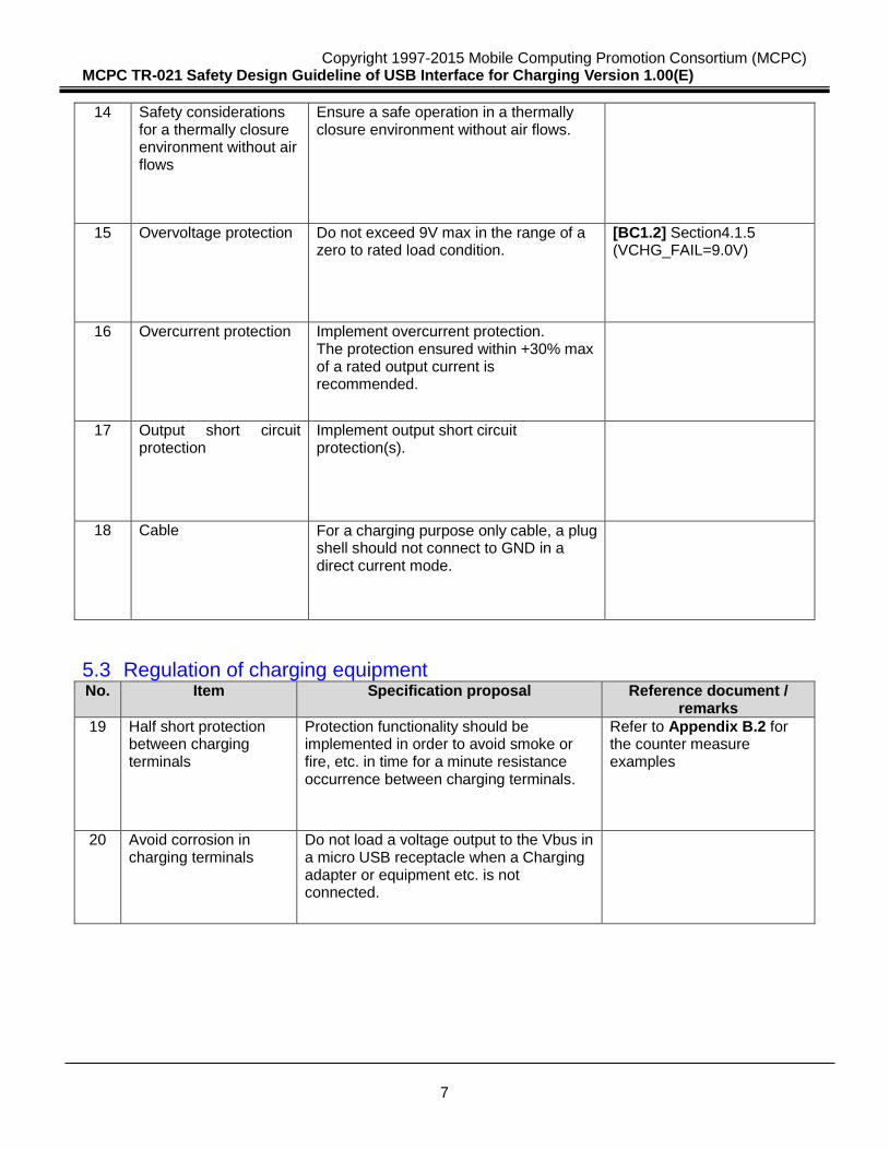
14 Safety considerations for a thermally closure environment without air flows
Ensure a safe operation in a thermally closure environment without air flows.
15 Overvoltage protection Do not exceed 9V max in the range of a zero to rated load condition.
[BC1.2] Section4.1.5 (VCHG_FAIL=9.0V)
16 Overcurrent protection Implement overcurrent protection. The protection ensured within +30% max of a rated output current is recommended.
17 Output short circuit protection
Implement output short circuit protection(s).
18 Cable For a charging purpose only cable, a plug shell should not connect to GND in a direct current mode.
5.3 Regulation of charging equipment No. Item Specification proposal Reference document /
remarks
19 Half short protection between charging terminals
Protection functionality should be implemented in order to avoid smoke or fire, etc. in time for a minute resistance occurrence between charging terminals.
Refer to Appendix B.2 for the counter measure examples
20 Avoid corrosion in charging terminals
Do not load a voltage output to the Vbus in a micro USB receptacle when a Charging adapter or equipment etc. is not connected.
Copyright 1997-2015 Mobile Computing Promotion Consortium (MCPC) MCPC TR-021 Safety Design Guideline of USB Interface for Charging Version 1.00(E)
8
6. Notes for designing a USB charging interface
6.1 The requirements for an AC/DC adapter The parameters for AC/DC Adapter defined at the Chapter 5 are as follows; Items 1-7 (all the items) in Chapter 5.1 Items 8-18 (all the items) in Chapter 5.2
6.2 The requirements for a mobile battery The parameters for a mobile battery defined at the Chapter 5 are as follows; Items 4-7 in the Chapter 5.1 Items 9, 11 and 13-18 in the Chapter 5.2
Copyright 1997-2015 Mobile Computing Promotion Consortium (MCPC) MCPC TR-021 Safety Design Guideline of USB Interface for Charging Version 1.00(E)
9
Appendix A. Reference specifications (Normative) [60950-1] IEC60950-1 Information technology equipment Safety Part 1: General requirements [61000-4-5] IEC61000-4-5 Electromagnetic compatibility (EMC) Part 4-5: Testing and measurement
techniques - Surge immunity test [BC1.2] Battery Charging Specification Revision 1.2 by USB Implementers Forum [USB2.0] Universal Serial Bus Specification Revision 2.0 by USB Implementers Forum [USB3.1] Universal Serial Bus Specification Revision 3.1 by USB Implementers Forum [EAMS] Electrical Appliance and Material Safety Law
Copyright 1997-2015 Mobile Computing Promotion Consortium (MCPC) MCPC TR-021 Safety Design Guideline of USB Interface for Charging Version 1.00(E)
10
Appendix B. Half short error and its counter measure examples
B.1 Examples for measures in charging adapter
- In order to avoid abnormal heat generation in a connector that may cause the danger of a fire and a skin burn, a charging adapter should implement temperature protecting functionality.
- Ensure the electrical circuit(V-I) properties of a charging adapter to avoid an abnormal heat generation upon generating half short at a charging terminal,. [Examples]
- Enlarge the termination voltage for a drooping characteristic, or eliminate a drooping characteristic. -The cycle of an automatic recovery (auto-restart) after entering a short protection must be long
enough to avoid a frequent activation of the protection function, or no automatic recovery is supported.
B.2 Examples for measures in charging equipment - Even in case of occurrence of minute resistances in between charging terminals (especially in between a connector power source terminal and a connector shell), smoke and fire can be prevented by implementing the following (1) or (2) of the measures to the chargers as set forth in this Guideline [Example (1) of the measures] A capacitor is mounted between a connector shell and the GND electrode of a substrate, without directly grounding the conductive connector shell in the Micro USB connector (receptacle) of equipment to a GND of a substrate. In addition, it is desirable to set a capacitance value in consideration of the influence over USB data communications. [Example (2) of measures] The PTC (Positive Temperature Coefficient) thermistor is mounted between a connector shell and a substrate GND electrode without directly grounding the conductive connector shell in the Micro USB connector (receptacle) of equipment to GND in a substrate,
Copyright 1997-2015 Mobile Computing Promotion Consortium (MCPC) MCPC TR-021 Safety Design Guideline of USB Interface for Charging Version 1.00(E)
11
Appendix C. Related specifications (for further investigation)
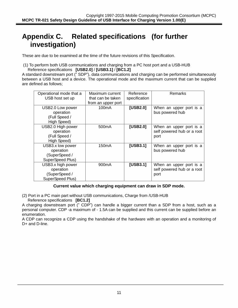
These are due to be examined at the time of the future revisions of this Specification. (1) To perform both USB communications and charging from a PC host port and a USB-HUB Reference specifications [USB2.0] / [USB3.1] / [BC1.2] A standard downstream port (” SDP”), data communications and charging can be performed simultaneously between a USB host and a device. The operational mode and the maximum current that can be supplied are defined as follows;
Operational mode that a USB host set up
Maximum current that can be taken
from an upper port
Reference specification
Remarks
USB2.0 Low power operation
(Full Speed / High Speed)
100mA [USB2.0] When an upper port is a bus powered hub
USB2.0 High power operation
(Full Speed / High Speed)
500mA [USB2.0] When an upper port is a self powered hub or a root port
USB3.x low power operation
(SuperSpeed / SuperSpeed Plus)
150mA [USB3.1] When an upper port is a bus powered hub
USB3.x high power operation
(SuperSpeed / SuperSpeed Plus)
900mA [USB3.1] When an upper port is a self powered hub or a root port
Current value which charging equipment can draw in SDP mode. (2) Port in a PC main part without USB communications, Charge from /USB-HUB Reference specifications [BC1.2] A charging downstream port (” CDP”) can handle a bigger current than a SDP from a host, such as a personal computer. CDP -a maximum of - 1.5A can be supplied and this current can be supplied before an enumeration. A CDP can recognize a CDP using the handshake of the hardware with an operation and a monitoring of D+ and D-line.
Copyright 1997-2015 Mobile Computing Promotion Consortium (MCPC) MCPC TR-021 Safety Design Guideline of USB Interface for Charging Version 1.00(E)
12
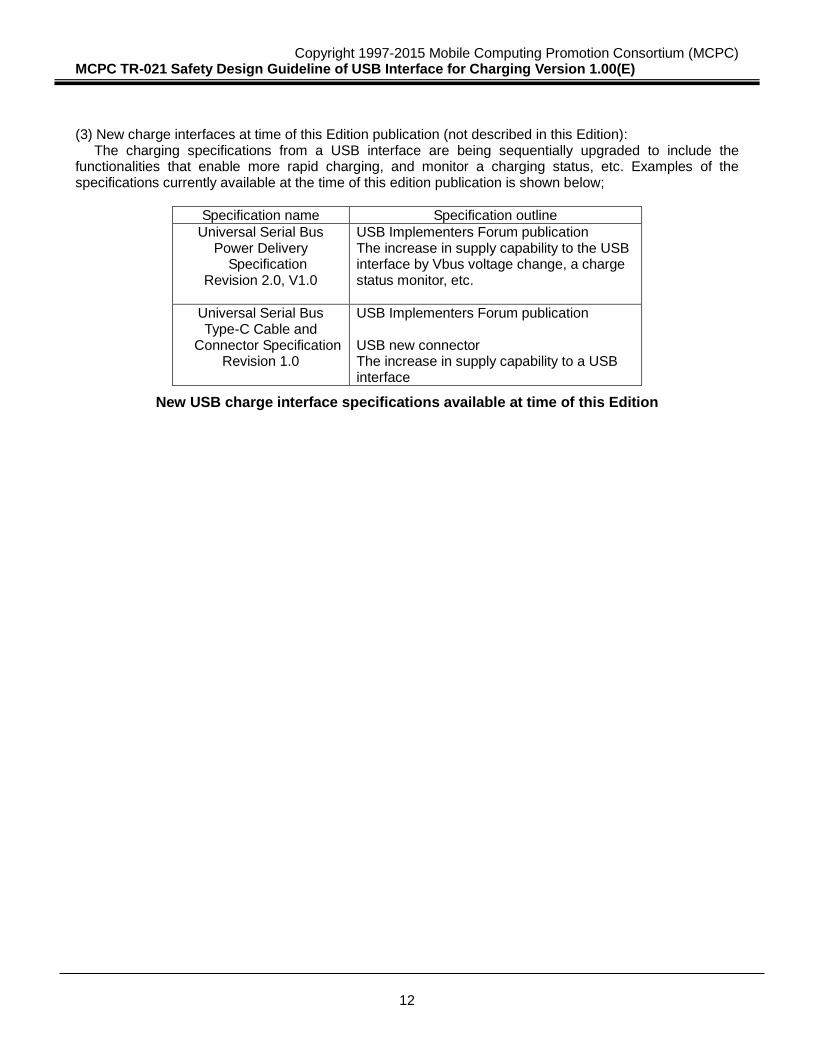
(3) New charge interfaces at time of this Edition publication (not described in this Edition):
The charging specifications from a USB interface are being sequentially upgraded to include the functionalities that enable more rapid charging, and monitor a charging status, etc. Examples of the specifications currently available at the time of this edition publication is shown below;
Specification name Specification outline
Universal Serial Bus Power Delivery
Specification Revision 2.0, V1.0
USB Implementers Forum publication The increase in supply capability to the USB interface by Vbus voltage change, a charge status monitor, etc.
Universal Serial Bus Type-C Cable and
Connector Specification Revision 1.0
USB Implementers Forum publication USB new connector The increase in supply capability to a USB interface
New USB charge interface specifications available at time of this Edition


![FOMA USB インタフェースを利用するための技術参 …...[2] MCPC GL-005 MCPC USB Implementation Guideline –Technical Specification- Ver.1.0 [3] Universal Serial Bus](https://static.fdocuments.net/doc/165x107/5f8e4b087986be0a230f203a/foma-usb-fffce-2-mcpc-gl-005.jpg)